EP4354013B1 - Kryogene anordnung - Google Patents
Kryogene anordnung Download PDFInfo
- Publication number
- EP4354013B1 EP4354013B1 EP23200513.2A EP23200513A EP4354013B1 EP 4354013 B1 EP4354013 B1 EP 4354013B1 EP 23200513 A EP23200513 A EP 23200513A EP 4354013 B1 EP4354013 B1 EP 4354013B1
- Authority
- EP
- European Patent Office
- Prior art keywords
- receptacle
- cryogenic
- fluidic equipment
- fluidic
- equipment
- Prior art date
- Legal status (The legal status is an assumption and is not a legal conclusion. Google has not performed a legal analysis and makes no representation as to the accuracy of the status listed.)
- Active
Links
Images


Classifications
-
- F—MECHANICAL ENGINEERING; LIGHTING; HEATING; WEAPONS; BLASTING
- F17—STORING OR DISTRIBUTING GASES OR LIQUIDS
- F17C—VESSELS FOR CONTAINING OR STORING COMPRESSED, LIQUEFIED OR SOLIDIFIED GASES; FIXED-CAPACITY GAS-HOLDERS; FILLING VESSELS WITH, OR DISCHARGING FROM VESSELS, COMPRESSED, LIQUEFIED, OR SOLIDIFIED GASES
- F17C13/00—Details of vessels or of the filling or discharging of vessels
- F17C13/001—Thermal insulation specially adapted for cryogenic vessels
-
- F—MECHANICAL ENGINEERING; LIGHTING; HEATING; WEAPONS; BLASTING
- F17—STORING OR DISTRIBUTING GASES OR LIQUIDS
- F17C—VESSELS FOR CONTAINING OR STORING COMPRESSED, LIQUEFIED OR SOLIDIFIED GASES; FIXED-CAPACITY GAS-HOLDERS; FILLING VESSELS WITH, OR DISCHARGING FROM VESSELS, COMPRESSED, LIQUEFIED, OR SOLIDIFIED GASES
- F17C13/00—Details of vessels or of the filling or discharging of vessels
- F17C13/08—Mounting arrangements for vessels
-
- B—PERFORMING OPERATIONS; TRANSPORTING
- B60—VEHICLES IN GENERAL
- B60P—VEHICLES ADAPTED FOR LOAD TRANSPORTATION OR TO TRANSPORT, TO CARRY, OR TO COMPRISE SPECIAL LOADS OR OBJECTS
- B60P3/00—Vehicles adapted to transport, to carry or to comprise special loads or objects
- B60P3/22—Tank vehicles
-
- F—MECHANICAL ENGINEERING; LIGHTING; HEATING; WEAPONS; BLASTING
- F17—STORING OR DISTRIBUTING GASES OR LIQUIDS
- F17C—VESSELS FOR CONTAINING OR STORING COMPRESSED, LIQUEFIED OR SOLIDIFIED GASES; FIXED-CAPACITY GAS-HOLDERS; FILLING VESSELS WITH, OR DISCHARGING FROM VESSELS, COMPRESSED, LIQUEFIED, OR SOLIDIFIED GASES
- F17C13/00—Details of vessels or of the filling or discharging of vessels
-
- F—MECHANICAL ENGINEERING; LIGHTING; HEATING; WEAPONS; BLASTING
- F17—STORING OR DISTRIBUTING GASES OR LIQUIDS
- F17C—VESSELS FOR CONTAINING OR STORING COMPRESSED, LIQUEFIED OR SOLIDIFIED GASES; FIXED-CAPACITY GAS-HOLDERS; FILLING VESSELS WITH, OR DISCHARGING FROM VESSELS, COMPRESSED, LIQUEFIED, OR SOLIDIFIED GASES
- F17C3/00—Vessels not under pressure
-
- F—MECHANICAL ENGINEERING; LIGHTING; HEATING; WEAPONS; BLASTING
- F17—STORING OR DISTRIBUTING GASES OR LIQUIDS
- F17C—VESSELS FOR CONTAINING OR STORING COMPRESSED, LIQUEFIED OR SOLIDIFIED GASES; FIXED-CAPACITY GAS-HOLDERS; FILLING VESSELS WITH, OR DISCHARGING FROM VESSELS, COMPRESSED, LIQUEFIED, OR SOLIDIFIED GASES
- F17C9/00—Methods or apparatus for discharging liquefied or solidified gases from vessels not under pressure
-
- F—MECHANICAL ENGINEERING; LIGHTING; HEATING; WEAPONS; BLASTING
- F17—STORING OR DISTRIBUTING GASES OR LIQUIDS
- F17C—VESSELS FOR CONTAINING OR STORING COMPRESSED, LIQUEFIED OR SOLIDIFIED GASES; FIXED-CAPACITY GAS-HOLDERS; FILLING VESSELS WITH, OR DISCHARGING FROM VESSELS, COMPRESSED, LIQUEFIED, OR SOLIDIFIED GASES
- F17C2201/00—Vessel construction, in particular geometry, arrangement or size
- F17C2201/01—Shape
- F17C2201/0104—Shape cylindrical
-
- F—MECHANICAL ENGINEERING; LIGHTING; HEATING; WEAPONS; BLASTING
- F17—STORING OR DISTRIBUTING GASES OR LIQUIDS
- F17C—VESSELS FOR CONTAINING OR STORING COMPRESSED, LIQUEFIED OR SOLIDIFIED GASES; FIXED-CAPACITY GAS-HOLDERS; FILLING VESSELS WITH, OR DISCHARGING FROM VESSELS, COMPRESSED, LIQUEFIED, OR SOLIDIFIED GASES
- F17C2201/00—Vessel construction, in particular geometry, arrangement or size
- F17C2201/03—Orientation
- F17C2201/035—Orientation with substantially horizontal main axis
-
- F—MECHANICAL ENGINEERING; LIGHTING; HEATING; WEAPONS; BLASTING
- F17—STORING OR DISTRIBUTING GASES OR LIQUIDS
- F17C—VESSELS FOR CONTAINING OR STORING COMPRESSED, LIQUEFIED OR SOLIDIFIED GASES; FIXED-CAPACITY GAS-HOLDERS; FILLING VESSELS WITH, OR DISCHARGING FROM VESSELS, COMPRESSED, LIQUEFIED, OR SOLIDIFIED GASES
- F17C2201/00—Vessel construction, in particular geometry, arrangement or size
- F17C2201/05—Size
- F17C2201/054—Size medium (>1 m3)
-
- F—MECHANICAL ENGINEERING; LIGHTING; HEATING; WEAPONS; BLASTING
- F17—STORING OR DISTRIBUTING GASES OR LIQUIDS
- F17C—VESSELS FOR CONTAINING OR STORING COMPRESSED, LIQUEFIED OR SOLIDIFIED GASES; FIXED-CAPACITY GAS-HOLDERS; FILLING VESSELS WITH, OR DISCHARGING FROM VESSELS, COMPRESSED, LIQUEFIED, OR SOLIDIFIED GASES
- F17C2203/00—Vessel construction, in particular walls or details thereof
- F17C2203/03—Thermal insulations
- F17C2203/0391—Thermal insulations by vacuum
-
- F—MECHANICAL ENGINEERING; LIGHTING; HEATING; WEAPONS; BLASTING
- F17—STORING OR DISTRIBUTING GASES OR LIQUIDS
- F17C—VESSELS FOR CONTAINING OR STORING COMPRESSED, LIQUEFIED OR SOLIDIFIED GASES; FIXED-CAPACITY GAS-HOLDERS; FILLING VESSELS WITH, OR DISCHARGING FROM VESSELS, COMPRESSED, LIQUEFIED, OR SOLIDIFIED GASES
- F17C2205/00—Vessel construction, in particular mounting arrangements, attachments or identifications means
- F17C2205/01—Mounting arrangements
- F17C2205/0103—Exterior arrangements
- F17C2205/0111—Boxes
-
- F—MECHANICAL ENGINEERING; LIGHTING; HEATING; WEAPONS; BLASTING
- F17—STORING OR DISTRIBUTING GASES OR LIQUIDS
- F17C—VESSELS FOR CONTAINING OR STORING COMPRESSED, LIQUEFIED OR SOLIDIFIED GASES; FIXED-CAPACITY GAS-HOLDERS; FILLING VESSELS WITH, OR DISCHARGING FROM VESSELS, COMPRESSED, LIQUEFIED, OR SOLIDIFIED GASES
- F17C2205/00—Vessel construction, in particular mounting arrangements, attachments or identifications means
- F17C2205/01—Mounting arrangements
- F17C2205/0123—Mounting arrangements characterised by number of vessels
- F17C2205/0126—One vessel
-
- F—MECHANICAL ENGINEERING; LIGHTING; HEATING; WEAPONS; BLASTING
- F17—STORING OR DISTRIBUTING GASES OR LIQUIDS
- F17C—VESSELS FOR CONTAINING OR STORING COMPRESSED, LIQUEFIED OR SOLIDIFIED GASES; FIXED-CAPACITY GAS-HOLDERS; FILLING VESSELS WITH, OR DISCHARGING FROM VESSELS, COMPRESSED, LIQUEFIED, OR SOLIDIFIED GASES
- F17C2205/00—Vessel construction, in particular mounting arrangements, attachments or identifications means
- F17C2205/03—Fluid connections, filters, valves, closure means or other attachments
- F17C2205/0302—Fittings, valves, filters, or components in connection with the gas storage device
- F17C2205/0352—Pipes
- F17C2205/0355—Insulation thereof
-
- F—MECHANICAL ENGINEERING; LIGHTING; HEATING; WEAPONS; BLASTING
- F17—STORING OR DISTRIBUTING GASES OR LIQUIDS
- F17C—VESSELS FOR CONTAINING OR STORING COMPRESSED, LIQUEFIED OR SOLIDIFIED GASES; FIXED-CAPACITY GAS-HOLDERS; FILLING VESSELS WITH, OR DISCHARGING FROM VESSELS, COMPRESSED, LIQUEFIED, OR SOLIDIFIED GASES
- F17C2205/00—Vessel construction, in particular mounting arrangements, attachments or identifications means
- F17C2205/03—Fluid connections, filters, valves, closure means or other attachments
- F17C2205/0302—Fittings, valves, filters, or components in connection with the gas storage device
- F17C2205/0352—Pipes
- F17C2205/0358—Pipes coaxial
-
- F—MECHANICAL ENGINEERING; LIGHTING; HEATING; WEAPONS; BLASTING
- F17—STORING OR DISTRIBUTING GASES OR LIQUIDS
- F17C—VESSELS FOR CONTAINING OR STORING COMPRESSED, LIQUEFIED OR SOLIDIFIED GASES; FIXED-CAPACITY GAS-HOLDERS; FILLING VESSELS WITH, OR DISCHARGING FROM VESSELS, COMPRESSED, LIQUEFIED, OR SOLIDIFIED GASES
- F17C2205/00—Vessel construction, in particular mounting arrangements, attachments or identifications means
- F17C2205/03—Fluid connections, filters, valves, closure means or other attachments
- F17C2205/0302—Fittings, valves, filters, or components in connection with the gas storage device
- F17C2205/0352—Pipes
- F17C2205/0364—Pipes flexible or articulated, e.g. a hose
-
- F—MECHANICAL ENGINEERING; LIGHTING; HEATING; WEAPONS; BLASTING
- F17—STORING OR DISTRIBUTING GASES OR LIQUIDS
- F17C—VESSELS FOR CONTAINING OR STORING COMPRESSED, LIQUEFIED OR SOLIDIFIED GASES; FIXED-CAPACITY GAS-HOLDERS; FILLING VESSELS WITH, OR DISCHARGING FROM VESSELS, COMPRESSED, LIQUEFIED, OR SOLIDIFIED GASES
- F17C2205/00—Vessel construction, in particular mounting arrangements, attachments or identifications means
- F17C2205/03—Fluid connections, filters, valves, closure means or other attachments
- F17C2205/0302—Fittings, valves, filters, or components in connection with the gas storage device
- F17C2205/037—Quick connecting means, e.g. couplings
-
- F—MECHANICAL ENGINEERING; LIGHTING; HEATING; WEAPONS; BLASTING
- F17—STORING OR DISTRIBUTING GASES OR LIQUIDS
- F17C—VESSELS FOR CONTAINING OR STORING COMPRESSED, LIQUEFIED OR SOLIDIFIED GASES; FIXED-CAPACITY GAS-HOLDERS; FILLING VESSELS WITH, OR DISCHARGING FROM VESSELS, COMPRESSED, LIQUEFIED, OR SOLIDIFIED GASES
- F17C2221/00—Handled fluid, in particular type of fluid
- F17C2221/01—Pure fluids
- F17C2221/012—Hydrogen
-
- F—MECHANICAL ENGINEERING; LIGHTING; HEATING; WEAPONS; BLASTING
- F17—STORING OR DISTRIBUTING GASES OR LIQUIDS
- F17C—VESSELS FOR CONTAINING OR STORING COMPRESSED, LIQUEFIED OR SOLIDIFIED GASES; FIXED-CAPACITY GAS-HOLDERS; FILLING VESSELS WITH, OR DISCHARGING FROM VESSELS, COMPRESSED, LIQUEFIED, OR SOLIDIFIED GASES
- F17C2221/00—Handled fluid, in particular type of fluid
- F17C2221/01—Pure fluids
- F17C2221/016—Noble gases (Ar, Kr, Xe)
- F17C2221/017—Helium
-
- F—MECHANICAL ENGINEERING; LIGHTING; HEATING; WEAPONS; BLASTING
- F17—STORING OR DISTRIBUTING GASES OR LIQUIDS
- F17C—VESSELS FOR CONTAINING OR STORING COMPRESSED, LIQUEFIED OR SOLIDIFIED GASES; FIXED-CAPACITY GAS-HOLDERS; FILLING VESSELS WITH, OR DISCHARGING FROM VESSELS, COMPRESSED, LIQUEFIED, OR SOLIDIFIED GASES
- F17C2223/00—Handled fluid before transfer, i.e. state of fluid when stored in the vessel or before transfer from the vessel
- F17C2223/01—Handled fluid before transfer, i.e. state of fluid when stored in the vessel or before transfer from the vessel characterised by the phase
- F17C2223/0146—Two-phase
- F17C2223/0153—Liquefied gas, e.g. LPG, GPL
- F17C2223/0161—Liquefied gas, e.g. LPG, GPL cryogenic, e.g. LNG, GNL, PLNG
-
- F—MECHANICAL ENGINEERING; LIGHTING; HEATING; WEAPONS; BLASTING
- F17—STORING OR DISTRIBUTING GASES OR LIQUIDS
- F17C—VESSELS FOR CONTAINING OR STORING COMPRESSED, LIQUEFIED OR SOLIDIFIED GASES; FIXED-CAPACITY GAS-HOLDERS; FILLING VESSELS WITH, OR DISCHARGING FROM VESSELS, COMPRESSED, LIQUEFIED, OR SOLIDIFIED GASES
- F17C2223/00—Handled fluid before transfer, i.e. state of fluid when stored in the vessel or before transfer from the vessel
- F17C2223/03—Handled fluid before transfer, i.e. state of fluid when stored in the vessel or before transfer from the vessel characterised by the pressure level
- F17C2223/033—Small pressure, e.g. for liquefied gas
-
- F—MECHANICAL ENGINEERING; LIGHTING; HEATING; WEAPONS; BLASTING
- F17—STORING OR DISTRIBUTING GASES OR LIQUIDS
- F17C—VESSELS FOR CONTAINING OR STORING COMPRESSED, LIQUEFIED OR SOLIDIFIED GASES; FIXED-CAPACITY GAS-HOLDERS; FILLING VESSELS WITH, OR DISCHARGING FROM VESSELS, COMPRESSED, LIQUEFIED, OR SOLIDIFIED GASES
- F17C2227/00—Transfer of fluids, i.e. method or means for transferring the fluid; Heat exchange with the fluid
- F17C2227/01—Propulsion of the fluid
- F17C2227/0128—Propulsion of the fluid with pumps or compressors
- F17C2227/0135—Pumps
-
- F—MECHANICAL ENGINEERING; LIGHTING; HEATING; WEAPONS; BLASTING
- F17—STORING OR DISTRIBUTING GASES OR LIQUIDS
- F17C—VESSELS FOR CONTAINING OR STORING COMPRESSED, LIQUEFIED OR SOLIDIFIED GASES; FIXED-CAPACITY GAS-HOLDERS; FILLING VESSELS WITH, OR DISCHARGING FROM VESSELS, COMPRESSED, LIQUEFIED, OR SOLIDIFIED GASES
- F17C2250/00—Accessories; Control means; Indicating, measuring or monitoring of parameters
- F17C2250/04—Indicating or measuring of parameters as input values
- F17C2250/0404—Parameters indicated or measured
- F17C2250/0443—Flow or movement of content
-
- F—MECHANICAL ENGINEERING; LIGHTING; HEATING; WEAPONS; BLASTING
- F17—STORING OR DISTRIBUTING GASES OR LIQUIDS
- F17C—VESSELS FOR CONTAINING OR STORING COMPRESSED, LIQUEFIED OR SOLIDIFIED GASES; FIXED-CAPACITY GAS-HOLDERS; FILLING VESSELS WITH, OR DISCHARGING FROM VESSELS, COMPRESSED, LIQUEFIED, OR SOLIDIFIED GASES
- F17C2260/00—Purposes of gas storage and gas handling
- F17C2260/03—Dealing with losses
- F17C2260/035—Dealing with losses of fluid
- F17C2260/037—Handling leaked fluid
-
- F—MECHANICAL ENGINEERING; LIGHTING; HEATING; WEAPONS; BLASTING
- F17—STORING OR DISTRIBUTING GASES OR LIQUIDS
- F17C—VESSELS FOR CONTAINING OR STORING COMPRESSED, LIQUEFIED OR SOLIDIFIED GASES; FIXED-CAPACITY GAS-HOLDERS; FILLING VESSELS WITH, OR DISCHARGING FROM VESSELS, COMPRESSED, LIQUEFIED, OR SOLIDIFIED GASES
- F17C2270/00—Applications
- F17C2270/01—Applications for fluid transport or storage
- F17C2270/0165—Applications for fluid transport or storage on the road
- F17C2270/0168—Applications for fluid transport or storage on the road by vehicles
- F17C2270/0171—Trucks
-
- F—MECHANICAL ENGINEERING; LIGHTING; HEATING; WEAPONS; BLASTING
- F17—STORING OR DISTRIBUTING GASES OR LIQUIDS
- F17C—VESSELS FOR CONTAINING OR STORING COMPRESSED, LIQUEFIED OR SOLIDIFIED GASES; FIXED-CAPACITY GAS-HOLDERS; FILLING VESSELS WITH, OR DISCHARGING FROM VESSELS, COMPRESSED, LIQUEFIED, OR SOLIDIFIED GASES
- F17C2270/00—Applications
- F17C2270/01—Applications for fluid transport or storage
- F17C2270/0165—Applications for fluid transport or storage on the road
- F17C2270/0168—Applications for fluid transport or storage on the road by vehicles
- F17C2270/0173—Railways
-
- Y—GENERAL TAGGING OF NEW TECHNOLOGICAL DEVELOPMENTS; GENERAL TAGGING OF CROSS-SECTIONAL TECHNOLOGIES SPANNING OVER SEVERAL SECTIONS OF THE IPC; TECHNICAL SUBJECTS COVERED BY FORMER USPC CROSS-REFERENCE ART COLLECTIONS [XRACs] AND DIGESTS
- Y02—TECHNOLOGIES OR APPLICATIONS FOR MITIGATION OR ADAPTATION AGAINST CLIMATE CHANGE
- Y02E—REDUCTION OF GREENHOUSE GAS [GHG] EMISSIONS, RELATED TO ENERGY GENERATION, TRANSMISSION OR DISTRIBUTION
- Y02E60/00—Enabling technologies; Technologies with a potential or indirect contribution to GHG emissions mitigation
- Y02E60/30—Hydrogen technology
- Y02E60/32—Hydrogen storage
-
- Y—GENERAL TAGGING OF NEW TECHNOLOGICAL DEVELOPMENTS; GENERAL TAGGING OF CROSS-SECTIONAL TECHNOLOGIES SPANNING OVER SEVERAL SECTIONS OF THE IPC; TECHNICAL SUBJECTS COVERED BY FORMER USPC CROSS-REFERENCE ART COLLECTIONS [XRACs] AND DIGESTS
- Y02—TECHNOLOGIES OR APPLICATIONS FOR MITIGATION OR ADAPTATION AGAINST CLIMATE CHANGE
- Y02E—REDUCTION OF GREENHOUSE GAS [GHG] EMISSIONS, RELATED TO ENERGY GENERATION, TRANSMISSION OR DISTRIBUTION
- Y02E60/00—Enabling technologies; Technologies with a potential or indirect contribution to GHG emissions mitigation
- Y02E60/30—Hydrogen technology
- Y02E60/34—Hydrogen distribution
Definitions
- the present invention relates to a cryogenic assembly and a method of handling such a cryogenic assembly.
- US5954101A discloses such a set.
- cryogenic assemblies comprising a cryogenic tank, a vacuum pipe and a receptacle for at least partially housing the pipe.
- a cryogenic assembly is, for example, a cryogenic semi-trailer or cryogenic tank car.
- Such a receptacle can also house fluidic equipment through which cryogenic fluid flows out of the tank.
- a known problem is that the space available inside the receptacle is such that removal of the fluidic equipment is then impossible. This is particularly problematic when it is necessary to replace the fluidic equipment with another, especially when it is necessary to add or replace a function to the fluidic equipment.
- a second distance separates the outlet end of the fluidic equipment from a plane orthogonal to the longitudinal axis and adjacent to the first longitudinal side, the second distance being greater than the first distance.
- the receptacle is mounted integrally with the cryogenic tank.
- the pipe is mounted free relative to the receptacle.
- the first longitudinal portion extends in a direction parallel to the direction in which the second longitudinal portion extends.
- the elbow is U-shaped.
- the first longitudinal portion extends along the longitudinal axis.
- the second longitudinal portion extends along the longitudinal axis.
- the fluidic equipment comprises a pump and/or a flow meter.
- the input end comprises a mechanical coupling device with the connecting flange.
- a seal is interposed between the mechanical coupling device and the connecting flange.
- the second end forms a free end of the second portion.
- the pipe comprises a tube, in particular a rigid tube
- the first end of the pipe is connected, in particular fluidically, to the cryogenic tank by welding.
- the pipe is fixed to the cryogenic tank, in particular by at least one fixing support connected to the external wall of the cryogenic tank.
- the cryogenic assembly comprises a cabinet of control mounted securely in relation to the cryogenic tank.
- the first longitudinal side is adjacent to a face of the cabinet.
- the first longitudinal side has an opening opening onto the face of the cabinet.
- the outlet end in the mounted position of the fluidic equipment, is closer to the first longitudinal side than to the second longitudinal side.
- the length of the first longitudinal portion is greater than the length of the fluidic equipment measured between its inlet and outlet ends.
- the elbow is configured to allow the fluid to flow in the second portion in a second direction, opposite to the first direction.
- the pipe enters the receptacle via the first longitudinal side.
- the cryogenic assembly comprises a pipe for distributing the cryogenic fluid, such as a hose, located at least partially inside the receptacle and being removably connected to the outlet end of the fluidic equipment.
- Such a cryogenic assembly allows suitable positioning of the cryogenic fluid distribution pipe relative to the cryogenic tank, which facilitates the distribution of the cryogenic fluid and/or limits the length of the distribution pipe.
- the pipe is of the thermally and vacuum insulated type.
- the second distance is less than 2 times the first distance, in particular less than 1.5 times the first distance, in particular less than 1.2 times the first distance.
- the receptacle comprises an upper wall in particular provided with a first plurality of orifices to allow ventilation of the receptacle.
- the upper wall comprises a plurality of vents, in particular progressive vents, to prevent a liquid from penetrating by gravity into the interior of the receptacle while allowing a gas located inside the receptacle to be evacuated in the event of a leak.
- the gills are obtained by stamping.
- the receptacle comprises a lower wall provided with a collection tray for collecting condensates and/or liquefied air.
- the receptacle comprises a front face extending along a plane parallel to the longitudinal axis and comprising at least one portion removable or a removable wall, to allow access to the interior of the receptacle.
- the receptacle comprises a side wall at the level of the first longitudinal side and/or at the level of the second longitudinal side, the side wall comprising in particular a non-rectilinear edge matching the external wall of the cryogenic tank.
- the cryogenic assembly comprises a collar fixed to the receptacle and configured to be arranged in a first configuration in which it at least partially encircles the fluidic equipment and allows guidance of the fluidic equipment to allow it to slide in the direction of the longitudinal axis.
- the collar is fixed to the receptacle by welding or screwed to the receptacle.
- the collar is configured to be arranged in a second configuration in which the fluidic equipment is free relative to the receptacle at least in a direction transverse to the longitudinal axis.
- the cryogenic fluid comprises liquid hydrogen or liquid helium.
- the method comprises a step of inerting the pipe prior to the step of separating the fluidic equipment from the connection flange.
- the receptacle is arranged at the rear of the cryogenic tank.
- the invention also relates to a vehicle such as a truck or a trailer or a semi-trailer or a tanker, comprising a cryogenic assembly as described above.
- the vehicle includes a control cabinet.
- the vehicle has a rear axle.
- the receptacle is arranged under the control cabinet or in the control cabinet.
- the receptacle is arranged at the rear axle, in particular above a mudguard.
- the receptacle is arranged at the rear of the vehicle.
- the vehicle extends along the longitudinal axis.
- the invention finally relates to the use of a cryogenic assembly as described above, on a truck or a trailer or a semi-trailer or a tanker.
- the front face comprises a second plurality of orifices to allow ventilation of the receptacle 3.
- the receptacle 3 comprises a side wall at the level of the first longitudinal side 2 and/or at the level of the second longitudinal side, the side wall comprising in particular a non-rectilinear edge matching the external wall of the cryogenic tank 50.
- the side wall comprises a third plurality of orifices to allow ventilation of the receptacle 3.
- FIG. 2 represents the cryogenic assembly 100 of the Figure 1 , the removable wall 15 having been removed, which allows access to the interior of the receptacle 3.
- the cryogenic assembly 100 comprises a pipe 8.
- the cryogenic assembly 100 comprises fluidic equipment 16 having an inlet end and an outlet end and being configured to be removably mounted in the receptacle 3.
- FIG. 2 represents the fluidic equipment 16 when it is in the mounted position.
- the fluidic equipment 16 comprises a mechanical coupling device 14 with the connecting flange 13. More precisely, the mechanical coupling device 14 is located at the inlet end and comprises, for example, a flange complementary to the connecting flange 13.
- the fluidic equipment 16 comprises a pump 9 and a flow meter 10.
- the cryogenic assembly 100 comprises a collar 11 fixed to the receptacle 3.
- the collar 11 is configured to be arranged in a first configuration in which it at least partially encircles the fluidic equipment 16 and allows guidance of the fluidic equipment 16 to allow it to slide in the direction of the longitudinal axis 1.
- the elbow 12 is configured to allow the fluid to flow in the second portion in a second direction, opposite to the first direction.
- the pipe 8 enters the receptacle 3 via the first longitudinal side 2.
- the cryogenic assembly 100 comprises a cryogenic fluid distribution pipe (not shown), such as a hose, located at least partially inside the receptacle 3 and being removably connected to the outlet end of the fluidic equipment 16.
- a cryogenic fluid distribution pipe such as a hose
- the pipe 8 is a thermally and vacuum insulated pipe.
- the pipe 8 is connected to the cryogenic tank 50 by a weld, the pipe 8 and the cryogenic tank 50 being in fluid communication, in particular via an opening.
- a second distance D2 separates the outlet end of the fluidic equipment from a plane orthogonal to the longitudinal axis 1 and adjacent to the first longitudinal side 2.
- the second distance D2 is strictly greater than the first distance D1.
- the outlet end is closer to the first longitudinal side 2 than to the second longitudinal side 5.
- the length of the first longitudinal portion is strictly greater than the length of the fluidic equipment 16, the length of the fluidic equipment 16 being measured between its inlet and outlet ends.
- the collar 11 is configured to be arranged in a second configuration in which the fluidic equipment 16 is free relative to the receptacle 3 at least in a direction transverse to the longitudinal axis 1.
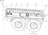
- FIG. 3 represents in elevation, the cryogenic assembly 100 when the fluidic equipment 16 is being dismantled relative to the receptacle 3.
- Receptacle 3 can be mounted on a vehicle such as a truck or a trailer or semi-trailer or tank car to enable the cryogenic tank 50 to be moved.
- cryogenic assembly 100 is particularly suitable for use in which the cryogenic tank 50 is mobile, which notably involves more severe constraints than in the case where the cryogenic tank is stationary.
- the vehicle may have a rear axle.
- the receptacle 3 may be mounted at the rear axle, for example above a mudguard.
- the pipe 8 enters the receptacle 3 through the first longitudinal side 2 and the cryogenic fluid distribution pipe exits the receptacle 3 through the first longitudinal side 2.
- the first longitudinal side 2 is arranged on the rear side of the trailer or semi-trailer. Such an arrangement makes it easier to distribute the cryogenic fluid to the rear of the trailer or semi-trailer while reducing the length of the distribution pipe.
- FIG. 4 represents the steps of a method for handling a cryogenic assembly 100 as described above.
- the method comprises a step E1 of inerting the pipe 8 prior to the step E2 of separating the fluidic equipment from the connection flange.
Landscapes
- Engineering & Computer Science (AREA)
- Mechanical Engineering (AREA)
- General Engineering & Computer Science (AREA)
- Health & Medical Sciences (AREA)
- Public Health (AREA)
- Transportation (AREA)
- Filling Or Discharging Of Gas Storage Vessels (AREA)
Claims (10)
- Kryogene Anordnung (100), umfassend:- einen kryogenen Tank (50);- einen Behälter (3), der sich entlang einer Längsachse (1) zwischen einer ersten Längsseite (2) und einer zweiten Längsseite (5) erstreckt, wobei der Behälter (3) außerhalb des kryogenen Tanks (50) gelegen ist;- eine Leitung (8), umfassend:- ein erstes Ende, das mit dem kryogenen Tank (50) verbunden ist, damit ein in dem kryogenen Tank (50) enthaltenes kryogenes Fluid in der Leitung (8) zirkulieren kann;- ein zweites Ende, das innerhalb des Behälters (3) gelegen ist;dadurch gekennzeichnet, dass die Leitung umfasst:- einen ersten Längsabschnitt, der innerhalb des Behälters (3) gelegen ist und dazu ausgestaltet ist, dem kryogenen Fluid zu ermöglichen, in einem ersten Richtungssinn von dem ersten Ende zu dem zweiten Ende zu zirkulieren;- einen zweiten Längsabschnitt, der innerhalb des Behälters (3) gelegen ist;- einen Krümmer (12), der innerhalb des Behälters (3) zwischen dem ersten Abschnitt und dem zweiten Abschnitt gelegen ist;- einen Anschlussflansch (13), der einstückig mit der Leitung (8) ist und zwischen dem Krümmer (12) und dem zweiten Ende gelegen ist, wobei der Anschlussflansch (13) in einem ersten Abstand (D1) von dem zweiten Ende gelegen ist;und dadurch, dass die Anordnung umfasst:- eine Fluideinrichtung (16), die ein Einlassende und ein Auslassende umfasst und dazu ausgestaltet ist, lösbar in dem Behälter (3) angebracht zu werden, wobei in der angebrachten Stellung:- das zweite Ende mindestens teilweise über das Einlassende in den Innenraum der Fluideinrichtung (16) eingeführt ist;- die Fluideinrichtung (16) an den Anschlussflansch (13) angeschlossen ist, um dem Kryofluid zu ermöglichen, durch das Einlassende in die Fluideinrichtung (16) einzutreten.
- Kryogene Anordnung (100) nach dem vorhergehenden Anspruch, wobei, in der angebrachten Stellung der Fluideinrichtung (16), ein zweiter Abstand (D2) das Auslassende der Fluideinrichtung von einer Ebene trennt, die senkrecht zu der Längsachse (1) verläuft und an die erste Längsseite (2) angrenzt, wobei der zweite Abstand (D2) größer als der erste Abstand (D1) ist.
- Kryogene Anordnung (100) nach einem der vorhergehenden Ansprüche, wobei die Länge des ersten Längsabschnitts größer als die Länge der Fluideinrichtung (16), gemessen zwischen ihren Einlass- und Auslassenden, ist.
- Kryogene Anordnung (100) nach einem der vorhergehenden Ansprüche, wobei der Krümmer (12) dazu ausgestaltet ist, dem Fluid zu ermöglichen, in dem zweiten Abschnitt entlang eines zweiten Richtungssinns zu strömen, der entgegengesetzt zu dem ersten Richtungssinn ist.
- Kryogene Anordnung (100) nach einem der vorhergehenden Ansprüche, wobei die Leitung (8) in den Behälter (3) durch die erste Längsseite (2) eindringt.
- Kryogene Anordnung (100) nach einem der vorhergehenden Ansprüche, umfassend ein Ausgaberohr für das kryogene Fluid wie etwa einen Schlauch, das mindestens teilweise innerhalb des Behälters (3) gelegen ist und lösbar mit dem Auslassende der Fluideinrichtung (16) verbunden ist.
- Kryogene Anordnung (100) nach einem der vorhergehenden Ansprüche, wobei der Behälter (3) eine untere Wand umfasst, die mit einer Auffangwanne (6) zum Auffangen von Kondensat und/oder von verflüssigter Luft versehen ist.
- Kryogene Anordnung (100) nach einem der vorhergehenden Ansprüche, umfassend eine Schelle (11), die an dem Behälter (3) befestigt ist und dazu ausgestaltet ist, in einer ersten Konfiguration angeordnet zu werden, in der sie die Fluideinrichtung (16) mindestens teilweise umschließt und ein Führen der Fluideinrichtung (16) zulässt, um deren Gleiten in Richtung der Längsachse (1) zu ermöglichen.
- Kryogene Anordnung (100) nach dem vorhergehenden Anspruch, wobei die Schelle (11) dazu ausgestaltet ist, in einer zweiten Konfiguration angeordnet zu werden, in der die Fluideinrichtung (16) in Bezug auf den Behälter (3) mindestens entlang einer quer zu der Längsachse (1) verlaufenden Richtung frei ist.
- Verfahren zur Handhabung einer kryogenen Anordnung (100) nach einem der vorhergehenden Ansprüche, umfassend die folgenden Schritte:- Trennen (E2) der Fluideinrichtung (16) von dem Anschlussflansch (13);- Verlagern (E3) der Fluideinrichtung (16), indem man sie entlang der Längsachse (1) in Richtung der ersten Längsseite (2) gleiten lässt, bis das zweite Ende außerhalb der Fluideinrichtung (16) gelegen ist;- Herausziehen (E4) der Fluideinrichtung (16) aus dem Innenraum des Behälters (3).
Applications Claiming Priority (1)
| Application Number | Priority Date | Filing Date | Title |
|---|---|---|---|
| FR2210537A FR3140874B1 (fr) | 2022-10-13 | 2022-10-13 | Ensemble cryogénique |
Publications (2)
| Publication Number | Publication Date |
|---|---|
| EP4354013A1 EP4354013A1 (de) | 2024-04-17 |
| EP4354013B1 true EP4354013B1 (de) | 2025-04-09 |
Family
ID=84569404
Family Applications (1)
| Application Number | Title | Priority Date | Filing Date |
|---|---|---|---|
| EP23200513.2A Active EP4354013B1 (de) | 2022-10-13 | 2023-09-28 | Kryogene anordnung |
Country Status (7)
| Country | Link |
|---|---|
| US (1) | US12510209B2 (de) |
| EP (1) | EP4354013B1 (de) |
| JP (1) | JP2024058622A (de) |
| KR (1) | KR20240052663A (de) |
| CN (1) | CN117889355A (de) |
| CA (1) | CA3212921A1 (de) |
| FR (1) | FR3140874B1 (de) |
Family Cites Families (9)
| Publication number | Priority date | Publication date | Assignee | Title |
|---|---|---|---|---|
| JP3129658B2 (ja) * | 1996-04-26 | 2001-01-31 | 本田技研工業株式会社 | 自動車の加圧燃料配管構造およびその配管漏れ検査方法 |
| US5954101A (en) * | 1996-06-14 | 1999-09-21 | Mve, Inc. | Mobile delivery and storage system for cryogenic fluids |
| FR2896302B1 (fr) * | 2006-01-18 | 2014-02-21 | Air Liquide | Systeme et procede de transfert de liquide cryogenique |
| PL3376013T3 (pl) * | 2017-03-17 | 2021-11-29 | Chart Inc. | Zintegrowany układ dostarczania płynu kriogenicznego oszczędzający przestrzeń |
| US20190316734A1 (en) * | 2018-04-11 | 2019-10-17 | United States Department of Transportation, FRA | Low Pressure Fuel Management and Delivery System for a Liquefied Natural Gas Rail Locomotive Tender |
| WO2020169191A1 (en) * | 2019-02-20 | 2020-08-27 | Wärtsilä Finland Oy | A gaseous fuel feeding system |
| CN110513595B (zh) * | 2019-06-20 | 2024-07-26 | 英嘉动力科技无锡有限公司 | 一种增压泵外置的气瓶结构 |
| CA3105833A1 (en) * | 2020-01-17 | 2021-07-17 | Trinity Tank Car, Inc. | Internal nozzle for a tank car |
| WO2022099336A1 (de) * | 2020-11-10 | 2022-05-19 | Cryoshelter Gmbh | System umfassend einen kryobehälter und einen thermischen siphon |
-
2022
- 2022-10-13 FR FR2210537A patent/FR3140874B1/fr active Active
-
2023
- 2023-09-19 CA CA3212921A patent/CA3212921A1/fr active Pending
- 2023-09-28 EP EP23200513.2A patent/EP4354013B1/de active Active
- 2023-10-10 KR KR1020230134154A patent/KR20240052663A/ko active Pending
- 2023-10-10 JP JP2023175037A patent/JP2024058622A/ja active Pending
- 2023-10-10 US US18/378,505 patent/US12510209B2/en active Active
- 2023-10-12 CN CN202311318347.6A patent/CN117889355A/zh active Pending
Also Published As
| Publication number | Publication date |
|---|---|
| US20240125429A1 (en) | 2024-04-18 |
| FR3140874B1 (fr) | 2024-09-06 |
| CA3212921A1 (fr) | 2024-04-13 |
| CN117889355A (zh) | 2024-04-16 |
| US12510209B2 (en) | 2025-12-30 |
| EP4354013A1 (de) | 2024-04-17 |
| JP2024058622A (ja) | 2024-04-25 |
| FR3140874A1 (fr) | 2024-04-19 |
| KR20240052663A (ko) | 2024-04-23 |
Similar Documents
| Publication | Publication Date | Title |
|---|---|---|
| EP2875220B1 (de) | Entlüftungstank sowie motorfahrzeugkühlsystem mit solch einem entlüftungstank | |
| EP4004427B1 (de) | Druckgasabgabevorrichtung | |
| EP3408004B1 (de) | Kraftstofffilter mit einer montagevorrichtung, deren auslass durch ein ventil verschlossen wird, wenn ein filtereinsatz entfernt wird. | |
| CA2492166C (fr) | Turboreacteur comprenant un bras de raccord de servitudes, et le bras de raccord de servitudes | |
| FR3041695A1 (fr) | Reservoir de degazage et vehicule automobile comprenant un tel reservoir | |
| EP4354013B1 (de) | Kryogene anordnung | |
| FR3055926B1 (fr) | Agencement de fixation d'un reservoir de liquide dans un compartiment moteur d'un vehicule | |
| WO1986005567A1 (fr) | Dispositif de raccord rapide a un circuit de fluide | |
| EP0617788B1 (de) | Vorrichtung zur entnahme von flüssigkeitsproben aus einem tank oder aus einem chemischen reaktor | |
| FR2912434A1 (fr) | Cuve de reception pour dechets preleves par un vehicule de voirie | |
| FR2649053A1 (fr) | Chariot refrigere ayant un corps mobile par rapport a un chassis | |
| US4295504A (en) | Gasoline vapor recovery system | |
| FR3084056A1 (fr) | Ensemble de production d'energie et procede de purge de l'eau contenue dans un reservoir d'aeronef associe | |
| FR2915945A1 (fr) | Dispositif de stockage de liquide de frein pour vehicule automobile. | |
| EP1893341B1 (de) | Vorrichtung und anlage zum spritzen eines beschichtungsprodukts mit einem behältnis | |
| FR2537478A1 (fr) | Dispositif automatique de soudage de goujons | |
| FR2711338A1 (fr) | Dispositif de transfert de carburant depuis une poche annexe à la poche principale d'un réservoir de carburant. | |
| EP4521016B1 (de) | Behälter für eine kryogene verbindung und anordnung mit solch einem behälter | |
| EP0721809A1 (de) | Bewegliche Anordnung zum Gasabführen | |
| FR2554766A3 (fr) | Procede de montage des valves de mise a l'air libre des reservoirs de carburant | |
| FR2552169A1 (fr) | Appareil pour aspirer des liquides | |
| EP4692634A1 (de) | Speichervorrichtung für ein druckgas | |
| FR2815892A1 (fr) | Equipement de lavage de refroidisseur de lait | |
| EP0969240B1 (de) | Flüssigkeitsdruck- Erhöhungsgerät für Abgabeanlage | |
| FR2467820A1 (fr) | Moyen de protection adaptable sur les embouts de distribution de fluides liquides, en particulier de carburants liquides |
Legal Events
| Date | Code | Title | Description |
|---|---|---|---|
| PUAI | Public reference made under article 153(3) epc to a published international application that has entered the european phase |
Free format text: ORIGINAL CODE: 0009012 |
|
| STAA | Information on the status of an ep patent application or granted ep patent |
Free format text: STATUS: THE APPLICATION HAS BEEN PUBLISHED |
|
| AK | Designated contracting states |
Kind code of ref document: A1 Designated state(s): AL AT BE BG CH CY CZ DE DK EE ES FI FR GB GR HR HU IE IS IT LI LT LU LV MC ME MK MT NL NO PL PT RO RS SE SI SK SM TR |
|
| STAA | Information on the status of an ep patent application or granted ep patent |
Free format text: STATUS: REQUEST FOR EXAMINATION WAS MADE |
|
| 17P | Request for examination filed |
Effective date: 20241017 |
|
| RBV | Designated contracting states (corrected) |
Designated state(s): AL AT BE BG CH CY CZ DE DK EE ES FI FR GB GR HR HU IE IS IT LI LT LU LV MC ME MK MT NL NO PL PT RO RS SE SI SK SM TR |
|
| GRAP | Despatch of communication of intention to grant a patent |
Free format text: ORIGINAL CODE: EPIDOSNIGR1 |
|
| STAA | Information on the status of an ep patent application or granted ep patent |
Free format text: STATUS: GRANT OF PATENT IS INTENDED |
|
| INTG | Intention to grant announced |
Effective date: 20250115 |
|
| GRAS | Grant fee paid |
Free format text: ORIGINAL CODE: EPIDOSNIGR3 |
|
| GRAA | (expected) grant |
Free format text: ORIGINAL CODE: 0009210 |
|
| STAA | Information on the status of an ep patent application or granted ep patent |
Free format text: STATUS: THE PATENT HAS BEEN GRANTED |
|
| AK | Designated contracting states |
Kind code of ref document: B1 Designated state(s): AL AT BE BG CH CY CZ DE DK EE ES FI FR GB GR HR HU IE IS IT LI LT LU LV MC ME MK MT NL NO PL PT RO RS SE SI SK SM TR |
|
| REG | Reference to a national code |
Ref country code: GB Ref legal event code: FG4D Free format text: NOT ENGLISH |
|
| REG | Reference to a national code |
Ref country code: CH Ref legal event code: EP |
|
| REG | Reference to a national code |
Ref country code: DE Ref legal event code: R096 Ref document number: 602023002826 Country of ref document: DE |
|
| REG | Reference to a national code |
Ref country code: IE Ref legal event code: FG4D Free format text: LANGUAGE OF EP DOCUMENT: FRENCH |
|
| REG | Reference to a national code |
Ref country code: NL Ref legal event code: FP |
|
| REG | Reference to a national code |
Ref country code: AT Ref legal event code: MK05 Ref document number: 1783788 Country of ref document: AT Kind code of ref document: T Effective date: 20250409 |
|
| PG25 | Lapsed in a contracting state [announced via postgrant information from national office to epo] |
Ref country code: FI Free format text: LAPSE BECAUSE OF FAILURE TO SUBMIT A TRANSLATION OF THE DESCRIPTION OR TO PAY THE FEE WITHIN THE PRESCRIBED TIME-LIMIT Effective date: 20250409 Ref country code: PT Free format text: LAPSE BECAUSE OF FAILURE TO SUBMIT A TRANSLATION OF THE DESCRIPTION OR TO PAY THE FEE WITHIN THE PRESCRIBED TIME-LIMIT Effective date: 20250811 Ref country code: ES Free format text: LAPSE BECAUSE OF FAILURE TO SUBMIT A TRANSLATION OF THE DESCRIPTION OR TO PAY THE FEE WITHIN THE PRESCRIBED TIME-LIMIT Effective date: 20250409 |
|
| PGFP | Annual fee paid to national office [announced via postgrant information from national office to epo] |
Ref country code: DE Payment date: 20250919 Year of fee payment: 3 |
|
| REG | Reference to a national code |
Ref country code: LT Ref legal event code: MG9D |
|
| PG25 | Lapsed in a contracting state [announced via postgrant information from national office to epo] |
Ref country code: NO Free format text: LAPSE BECAUSE OF FAILURE TO SUBMIT A TRANSLATION OF THE DESCRIPTION OR TO PAY THE FEE WITHIN THE PRESCRIBED TIME-LIMIT Effective date: 20250709 Ref country code: GR Free format text: LAPSE BECAUSE OF FAILURE TO SUBMIT A TRANSLATION OF THE DESCRIPTION OR TO PAY THE FEE WITHIN THE PRESCRIBED TIME-LIMIT Effective date: 20250710 |
|
| PG25 | Lapsed in a contracting state [announced via postgrant information from national office to epo] |
Ref country code: PL Free format text: LAPSE BECAUSE OF FAILURE TO SUBMIT A TRANSLATION OF THE DESCRIPTION OR TO PAY THE FEE WITHIN THE PRESCRIBED TIME-LIMIT Effective date: 20250409 |
|
| PG25 | Lapsed in a contracting state [announced via postgrant information from national office to epo] |
Ref country code: BG Free format text: LAPSE BECAUSE OF FAILURE TO SUBMIT A TRANSLATION OF THE DESCRIPTION OR TO PAY THE FEE WITHIN THE PRESCRIBED TIME-LIMIT Effective date: 20250409 |
|
| PG25 | Lapsed in a contracting state [announced via postgrant information from national office to epo] |
Ref country code: HR Free format text: LAPSE BECAUSE OF FAILURE TO SUBMIT A TRANSLATION OF THE DESCRIPTION OR TO PAY THE FEE WITHIN THE PRESCRIBED TIME-LIMIT Effective date: 20250409 |
|
| PG25 | Lapsed in a contracting state [announced via postgrant information from national office to epo] |
Ref country code: AT Free format text: LAPSE BECAUSE OF FAILURE TO SUBMIT A TRANSLATION OF THE DESCRIPTION OR TO PAY THE FEE WITHIN THE PRESCRIBED TIME-LIMIT Effective date: 20250409 |
|
| PGFP | Annual fee paid to national office [announced via postgrant information from national office to epo] |
Ref country code: FR Payment date: 20250922 Year of fee payment: 3 |
|
| PG25 | Lapsed in a contracting state [announced via postgrant information from national office to epo] |
Ref country code: RS Free format text: LAPSE BECAUSE OF FAILURE TO SUBMIT A TRANSLATION OF THE DESCRIPTION OR TO PAY THE FEE WITHIN THE PRESCRIBED TIME-LIMIT Effective date: 20250709 |
|
| PG25 | Lapsed in a contracting state [announced via postgrant information from national office to epo] |
Ref country code: IS Free format text: LAPSE BECAUSE OF FAILURE TO SUBMIT A TRANSLATION OF THE DESCRIPTION OR TO PAY THE FEE WITHIN THE PRESCRIBED TIME-LIMIT Effective date: 20250809 |
|
| PG25 | Lapsed in a contracting state [announced via postgrant information from national office to epo] |
Ref country code: LV Free format text: LAPSE BECAUSE OF FAILURE TO SUBMIT A TRANSLATION OF THE DESCRIPTION OR TO PAY THE FEE WITHIN THE PRESCRIBED TIME-LIMIT Effective date: 20250409 |
|
| REG | Reference to a national code |
Ref country code: DE Ref legal event code: R097 Ref document number: 602023002826 Country of ref document: DE |
|
| PG25 | Lapsed in a contracting state [announced via postgrant information from national office to epo] |
Ref country code: DK Free format text: LAPSE BECAUSE OF FAILURE TO SUBMIT A TRANSLATION OF THE DESCRIPTION OR TO PAY THE FEE WITHIN THE PRESCRIBED TIME-LIMIT Effective date: 20250409 Ref country code: SM Free format text: LAPSE BECAUSE OF FAILURE TO SUBMIT A TRANSLATION OF THE DESCRIPTION OR TO PAY THE FEE WITHIN THE PRESCRIBED TIME-LIMIT Effective date: 20250409 |
|
| PG25 | Lapsed in a contracting state [announced via postgrant information from national office to epo] |
Ref country code: CZ Free format text: LAPSE BECAUSE OF FAILURE TO SUBMIT A TRANSLATION OF THE DESCRIPTION OR TO PAY THE FEE WITHIN THE PRESCRIBED TIME-LIMIT Effective date: 20250409 |
|
| PG25 | Lapsed in a contracting state [announced via postgrant information from national office to epo] |
Ref country code: EE Free format text: LAPSE BECAUSE OF FAILURE TO SUBMIT A TRANSLATION OF THE DESCRIPTION OR TO PAY THE FEE WITHIN THE PRESCRIBED TIME-LIMIT Effective date: 20250409 |
|
| PG25 | Lapsed in a contracting state [announced via postgrant information from national office to epo] |
Ref country code: SK Free format text: LAPSE BECAUSE OF FAILURE TO SUBMIT A TRANSLATION OF THE DESCRIPTION OR TO PAY THE FEE WITHIN THE PRESCRIBED TIME-LIMIT Effective date: 20250409 |
|
| PG25 | Lapsed in a contracting state [announced via postgrant information from national office to epo] |
Ref country code: IT Free format text: LAPSE BECAUSE OF FAILURE TO SUBMIT A TRANSLATION OF THE DESCRIPTION OR TO PAY THE FEE WITHIN THE PRESCRIBED TIME-LIMIT Effective date: 20250409 |
|
| PLBE | No opposition filed within time limit |
Free format text: ORIGINAL CODE: 0009261 |
|
| STAA | Information on the status of an ep patent application or granted ep patent |
Free format text: STATUS: NO OPPOSITION FILED WITHIN TIME LIMIT |
|
| REG | Reference to a national code |
Ref country code: CH Ref legal event code: L10 Free format text: ST27 STATUS EVENT CODE: U-0-0-L10-L00 (AS PROVIDED BY THE NATIONAL OFFICE) Effective date: 20260218 |
|
| PG25 | Lapsed in a contracting state [announced via postgrant information from national office to epo] |
Ref country code: RO Free format text: LAPSE BECAUSE OF FAILURE TO SUBMIT A TRANSLATION OF THE DESCRIPTION OR TO PAY THE FEE WITHIN THE PRESCRIBED TIME-LIMIT Effective date: 20250409 |
|
| 26N | No opposition filed |
Effective date: 20260112 |