EP4353540A2 - Stellantrieb zur einstellung eines anzeigeendgeräts und fahrzeug - Google Patents
Stellantrieb zur einstellung eines anzeigeendgeräts und fahrzeug Download PDFInfo
- Publication number
- EP4353540A2 EP4353540A2 EP24159607.1A EP24159607A EP4353540A2 EP 4353540 A2 EP4353540 A2 EP 4353540A2 EP 24159607 A EP24159607 A EP 24159607A EP 4353540 A2 EP4353540 A2 EP 4353540A2
- Authority
- EP
- European Patent Office
- Prior art keywords
- engaging portion
- display terminal
- locking
- actuator
- drive unit
- Prior art date
- Legal status (The legal status is an assumption and is not a legal conclusion. Google has not performed a legal analysis and makes no representation as to the accuracy of the status listed.)
- Pending
Links
Images


Classifications
-
- B—PERFORMING OPERATIONS; TRANSPORTING
- B60—VEHICLES IN GENERAL
- B60R—VEHICLES, VEHICLE FITTINGS, OR VEHICLE PARTS, NOT OTHERWISE PROVIDED FOR
- B60R11/00—Arrangements for holding or mounting articles, not otherwise provided for
- B60R11/02—Arrangements for holding or mounting articles, not otherwise provided for for radio sets, television sets, telephones, or the like; Arrangement of controls thereof
- B60R11/0229—Arrangements for holding or mounting articles, not otherwise provided for for radio sets, television sets, telephones, or the like; Arrangement of controls thereof for displays, e.g. cathodic tubes
- B60R11/0235—Arrangements for holding or mounting articles, not otherwise provided for for radio sets, television sets, telephones, or the like; Arrangement of controls thereof for displays, e.g. cathodic tubes of flat type, e.g. LCD
-
- F—MECHANICAL ENGINEERING; LIGHTING; HEATING; WEAPONS; BLASTING
- F16—ENGINEERING ELEMENTS AND UNITS; GENERAL MEASURES FOR PRODUCING AND MAINTAINING EFFECTIVE FUNCTIONING OF MACHINES OR INSTALLATIONS; THERMAL INSULATION IN GENERAL
- F16D—COUPLINGS FOR TRANSMITTING ROTATION; CLUTCHES; BRAKES
- F16D11/00—Clutches in which the members have interengaging parts
- F16D11/14—Clutches in which the members have interengaging parts with clutching members movable only axially
-
- F—MECHANICAL ENGINEERING; LIGHTING; HEATING; WEAPONS; BLASTING
- F16—ENGINEERING ELEMENTS AND UNITS; GENERAL MEASURES FOR PRODUCING AND MAINTAINING EFFECTIVE FUNCTIONING OF MACHINES OR INSTALLATIONS; THERMAL INSULATION IN GENERAL
- F16H—GEARING
- F16H1/00—Toothed gearings for conveying rotary motion
- F16H1/02—Toothed gearings for conveying rotary motion without gears having orbital motion
- F16H1/20—Toothed gearings for conveying rotary motion without gears having orbital motion involving more than two intermeshing members
- F16H1/203—Toothed gearings for conveying rotary motion without gears having orbital motion involving more than two intermeshing members with non-parallel axes
-
- F—MECHANICAL ENGINEERING; LIGHTING; HEATING; WEAPONS; BLASTING
- F16—ENGINEERING ELEMENTS AND UNITS; GENERAL MEASURES FOR PRODUCING AND MAINTAINING EFFECTIVE FUNCTIONING OF MACHINES OR INSTALLATIONS; THERMAL INSULATION IN GENERAL
- F16H—GEARING
- F16H57/00—General details of gearing
- F16H57/02—Gearboxes; Mounting gearing therein
- F16H57/039—Gearboxes for accommodating worm gears
-
- F—MECHANICAL ENGINEERING; LIGHTING; HEATING; WEAPONS; BLASTING
- F16—ENGINEERING ELEMENTS AND UNITS; GENERAL MEASURES FOR PRODUCING AND MAINTAINING EFFECTIVE FUNCTIONING OF MACHINES OR INSTALLATIONS; THERMAL INSULATION IN GENERAL
- F16M—FRAMES, CASINGS OR BEDS OF ENGINES, MACHINES OR APPARATUS, NOT SPECIFIC TO ENGINES, MACHINES OR APPARATUS PROVIDED FOR ELSEWHERE; STANDS; SUPPORTS
- F16M11/00—Stands or trestles as supports for apparatus or articles placed thereon ; Stands for scientific apparatus such as gravitational force meters
- F16M11/02—Heads
- F16M11/04—Means for attachment of apparatus; Means allowing adjustment of the apparatus relatively to the stand
- F16M11/06—Means for attachment of apparatus; Means allowing adjustment of the apparatus relatively to the stand allowing pivoting
- F16M11/10—Means for attachment of apparatus; Means allowing adjustment of the apparatus relatively to the stand allowing pivoting around a horizontal axis
- F16M11/105—Means for attachment of apparatus; Means allowing adjustment of the apparatus relatively to the stand allowing pivoting around a horizontal axis the horizontal axis being the roll axis, e.g. for creating a landscape-portrait rotation
-
- F—MECHANICAL ENGINEERING; LIGHTING; HEATING; WEAPONS; BLASTING
- F16—ENGINEERING ELEMENTS AND UNITS; GENERAL MEASURES FOR PRODUCING AND MAINTAINING EFFECTIVE FUNCTIONING OF MACHINES OR INSTALLATIONS; THERMAL INSULATION IN GENERAL
- F16M—FRAMES, CASINGS OR BEDS OF ENGINES, MACHINES OR APPARATUS, NOT SPECIFIC TO ENGINES, MACHINES OR APPARATUS PROVIDED FOR ELSEWHERE; STANDS; SUPPORTS
- F16M11/00—Stands or trestles as supports for apparatus or articles placed thereon ; Stands for scientific apparatus such as gravitational force meters
- F16M11/02—Heads
- F16M11/18—Heads with mechanism for moving the apparatus relatively to the stand
-
- F—MECHANICAL ENGINEERING; LIGHTING; HEATING; WEAPONS; BLASTING
- F16—ENGINEERING ELEMENTS AND UNITS; GENERAL MEASURES FOR PRODUCING AND MAINTAINING EFFECTIVE FUNCTIONING OF MACHINES OR INSTALLATIONS; THERMAL INSULATION IN GENERAL
- F16M—FRAMES, CASINGS OR BEDS OF ENGINES, MACHINES OR APPARATUS, NOT SPECIFIC TO ENGINES, MACHINES OR APPARATUS PROVIDED FOR ELSEWHERE; STANDS; SUPPORTS
- F16M13/00—Other supports for positioning apparatus or articles; Means for steadying hand-held apparatus or articles
- F16M13/02—Other supports for positioning apparatus or articles; Means for steadying hand-held apparatus or articles for supporting on, or attaching to, an object, e.g. tree, gate, window-frame, cycle
- F16M13/022—Other supports for positioning apparatus or articles; Means for steadying hand-held apparatus or articles for supporting on, or attaching to, an object, e.g. tree, gate, window-frame, cycle repositionable
-
- B—PERFORMING OPERATIONS; TRANSPORTING
- B60—VEHICLES IN GENERAL
- B60R—VEHICLES, VEHICLE FITTINGS, OR VEHICLE PARTS, NOT OTHERWISE PROVIDED FOR
- B60R11/00—Arrangements for holding or mounting articles, not otherwise provided for
- B60R2011/0042—Arrangements for holding or mounting articles, not otherwise provided for characterised by mounting means
- B60R2011/0049—Arrangements for holding or mounting articles, not otherwise provided for characterised by mounting means for non integrated articles
- B60R2011/0064—Connection with the article
- B60R2011/0066—Connection with the article using screws, bolts, rivets or the like
-
- B—PERFORMING OPERATIONS; TRANSPORTING
- B60—VEHICLES IN GENERAL
- B60R—VEHICLES, VEHICLE FITTINGS, OR VEHICLE PARTS, NOT OTHERWISE PROVIDED FOR
- B60R11/00—Arrangements for holding or mounting articles, not otherwise provided for
- B60R2011/0042—Arrangements for holding or mounting articles, not otherwise provided for characterised by mounting means
- B60R2011/0049—Arrangements for holding or mounting articles, not otherwise provided for characterised by mounting means for non integrated articles
- B60R2011/0064—Connection with the article
- B60R2011/0071—Connection with the article using latches, clips, clamps, straps or the like
-
- B—PERFORMING OPERATIONS; TRANSPORTING
- B60—VEHICLES IN GENERAL
- B60R—VEHICLES, VEHICLE FITTINGS, OR VEHICLE PARTS, NOT OTHERWISE PROVIDED FOR
- B60R11/00—Arrangements for holding or mounting articles, not otherwise provided for
- B60R2011/0042—Arrangements for holding or mounting articles, not otherwise provided for characterised by mounting means
- B60R2011/008—Adjustable or movable supports
- B60R2011/0085—Adjustable or movable supports with adjustment by rotation in their operational position
-
- B—PERFORMING OPERATIONS; TRANSPORTING
- B60—VEHICLES IN GENERAL
- B60R—VEHICLES, VEHICLE FITTINGS, OR VEHICLE PARTS, NOT OTHERWISE PROVIDED FOR
- B60R11/00—Arrangements for holding or mounting articles, not otherwise provided for
- B60R2011/0042—Arrangements for holding or mounting articles, not otherwise provided for characterised by mounting means
- B60R2011/008—Adjustable or movable supports
- B60R2011/0092—Adjustable or movable supports with motorization
Definitions
- the present disclosure belongs to the technical field of display terminal adjustment. It is particularly, but not exclusively, concerned with an actuator for adjusting a display terminal and a vehicle having the actuator.
- in-vehicle multimedia have increasingly rich functions and forms.
- Multifunctional large-size in-vehicle display terminals that can be connected to mobile phones, computers, or the Internet become a mainstream trend in future development.
- most of the in-vehicle display terminals are directly connected to a dashboard in a single mode of a landscape mode or a portrait mode.
- neither equal-scale and full-screen displaying of different specifications of image resources such as pictures and videos can be achieved, nor personal usage habits of different users can be satisfied.
- a pure manual mechanism or a pure electric mechanism is developed to rotate an in-vehicle display terminal.
- the mechanisms not only have complex structures, but also cannot satisfy manual or electric operation habits.
- the in-vehicle display terminal is not fixed, the in-vehicle display terminal is very likely to shake with vibration of a whole vehicle, and therefore needs to be improved.
- the present disclosure is intended to resolve at least one of technical problems existing in the prior art. To this end, the present disclosure proposes an actuator for adjusting a display terminal.
- the actuator has manual and automatic adjustment functions, and the two adjustment manners do not interfere with each other.
- the present disclosure further proposes a vehicle with the actuator.
- An actuator for adjusting a display terminal includes: a mounting unit configured to mount a display terminal; a clutch unit, a first engaging portion of the clutch unit being connected to the mounting unit, and a second engaging portion of the clutch unit being normally interlocked with the first engaging portion; and a drive unit, an output end of the drive unit being connected to the second engaging portion.
- a display terminal to be rotated manually and a display terminal to rotate automatically are coupled as a whole through the clutch unit, and the two screen switching methods do not interfere with each other.
- a vehicle includes a display terminal and the above actuator according to the present disclosure.
- the actuator is mounted on a vehicle body, and the display terminal is mounted on the mounting unit of the actuator.
- the vehicle according to the present disclosure has the same advantages as the above actuator compared to the prior art, and therefore details are not described herein again.
- orientations or position relationships indicated by terms such as “center”, “longitudinal”, “transverse”, “length”, “width”, “thickness”, “up”, “down”, “front”, “rear”, “left”, “right”, “vertical”, “horizontal”, “top”, “bottom”, “inner”, “outer”, “clockwise”, “counterclockwise”, “axial”, “radial”, and “circumferential” are orientations or position relationships shown based on the accompanying drawings, and are used only for ease of describing the present disclosure and simplifying the description, rather than indicating or implying that the apparatus or element should have a particular orientation or be constructed and operated in a particular orientation, and therefore, should not be construed as a limitation on the present disclosure.
- a feature defined to be “first” or “second” may explicitly or implicitly include one or more features. In the description of the present disclosure, unless stated otherwise, the meaning of "a plurality of" is two or more than two.
- connection may be a fixed connection, a detachable connection, or an integral connection; or the connection may be a mechanical connection or an electrical connection; or the connection may be a direct connection, an indirect connection through an intermediary, or internal communication between two components.
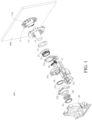
- the actuator 100 is configured to rotate the display terminal 200, for example, to switch the display terminal 200 between a landscape mode and a portrait mode, or rotate the display terminal 200 to other angles.
- the display terminal 200 may be a touch screen.
- the actuator 100 for adjusting the display terminal 200 includes: a mounting unit, a clutch unit, and a drive unit 30.
- the mounting unit is configured to mount the display terminal 200.
- the display terminal 200 may be fixedly mounted on the mounting unit, or may be detachably connected to the mounting unit.
- the mounting unit may include: a mounting bracket 11, a rotating turntable 13, and a mounting shaft 15.
- the mounting bracket 11 is configured to mount the display terminal 200, and the mounting bracket 11 is fixedly connected to the display terminal 200 (provided with a corresponding interface structure) by using a bolt, or the mounting bracket 11 may be integrated on a back of the display terminal 200.
- the mounting bracket 11 is fixedly connected to the rotating turntable 13 by a using buckle and two screws. In some embodiments, the mounting bracket 11 is detachably mounted on the rotating turntable 13.
- the rotating turntable 13 has a first groove 13a and a second groove 13b respectively located at two ends of the rotating turntable 13.
- the rotating turntable 13 has a first groove 13a at one end facing a first engaging portion 21 of the clutch unit. At least a part of the first engaging portion 21 is located in the first groove 13a to shorten an axial distance of the entire actuator 100. In some embodiments, as shown in FIG. 3 , the entire first engaging portion 21 is located in the first groove 13a, and at least a part of a second engaging portion 23 of the clutch unit is located in the first groove 13a. In a specific implementation, the entire second engaging portion 23 is located in the first groove 13a to further shorten the axial distance of the entire actuator 100. An overall axial length of the actuator 100 is shorter, so that a layout is more compact and proper, and a connection is tighter.
- the display terminal 200 is connected to the mounting unit 10 through a connection to the bracket 11, and the second groove 13b is adapted to receive and to be connected to the bracket 11.
- the connecting bracket 11 may be connected to the rotating turntable 13 through at least one of buckling and a bolt connection, and the connecting bracket 11 may be formed in a ring shape and include a plurality of claw-shaped connecting members distributed in a ring shape. The plurality of claw-shaped connecting members may protrude into and be inserted into the second groove 13b. In this way, not only the connecting bracket 11 intrudes into the rotating turntable 13, but also the plurality of claw-shaped connecting members define a cavity 11a. The cavity 11a is located behind the display terminal.
- At least a part of the rotating turntable 13 protrudes into the cavity 11a. In this way, a space of the mounting unit behind the display terminal 200 is properly utilized, and the overall axial length of the actuator 100 is significantly reduced, so that the layout is more compact and proper, and the connection is tighter.
- the rotating turntable 13 is dynamically coupled to the first engaging portion 21 by using a spline.
- a first spline is disposed on an end surface of the rotating turntable 13 facing away from the display terminal 200
- a second spline is disposed on an end surface of the first engaging portion 21 facing away from the second engaging portion 23, so that the rotating turntable 13 and the first engaging portion 21 are connected by using the first spline and the second spline.
- the rotating turntable 13 may also be integrally formed with the first engaging portion 21. In this way, a number of components to be assembled and assembling processes can be reduced.
- the rotating turntable 13 may have a disc shape, and a circular through hole is provided at a middle part of the rotating turntable 13, that is, the rotating turntable 13 is annular.
- the mounting shaft 15 extends axially from an inner periphery of the rotating turntable 13.
- the mounting shaft 15 may be a hollow shaft, and an inner peripheral wall of the mounting shaft 15 is coplanar with an inner peripheral wall of the circular through hole.
- the rotating turntable 13 is connected to the mounting shaft 15, and the mounting shaft 15 and the rotating turntable 13 may be formed integrally. Certainly, the mounting shaft 15 and the rotating turntable 13 may be separated and connected by using a buckling structure.
- the mounting shaft 15 penetrates the clutch unit and the drive unit 30.
- the mounting shaft 15 is configured to connect various components into a whole.
- the mounting shaft 15 does not transmit power.
- the mounting shaft 15 may rotate or not.
- the mounting shaft 15 may be a hollow shaft to reduce a weight and facilitate wiring.
- the clutch unit is located outside a housing of the drive unit 30.
- the clutch unit includes a first engaging portion 21 and a second engaging portion 23.
- the first engaging portion 21 of the clutch unit is connected to the mounting unit, and power may be transmitted between the first engaging portion 21 and the mounting unit.
- the second engaging portion 23 and the first engaging portion 21 of the clutch unit are normally interlocked with each other. "Normally interlocked with each other" means that the second engaging portion 23 and the first engaging portion 21 are interlocked with each other in a normal state.
- the second engaging portion 23 and the first engaging portion 21 When an external force applied between the second engaging portion 23 and the first engaging portion 21 is less than a pre-tension force existing when the second engaging portion 23 and the first engaging portion 21 are interlocked with each other, the second engaging portion 23 and the first engaging portion 21 remain a locked state, and the second engaging portion 23 and the first engaging portion 21 of the clutch unit are locked immediately after being engaged.
- the first engaging portion 21 and the second engaging portion 23 are engaged with each other and have a plurality of engaging positions.
- the mounting unit is configured to be manually rotatable to drive the first engaging portion 21 to rotatably switch between the plurality of engaging positions relative to the second engaging portion 23.
- the clutch unit may transmit a torque.
- the second engagement portion 23 and the first engagement portion 21 have a plurality of engaging positions.
- a plurality of engaging positions are formed on end surfaces of the first engaging portion 21 and the second engaging portion 23 opposite to each other.
- An output end of the drive unit 30 is dynamically coupled to the second engaging portion 23.
- the clutch unit is located outside the housing of the drive unit 30.
- the clutch unit includes a first engaging portion 21 and a second engaging portion 23 with opposite end surfaces.
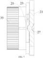
- One of the two end surfaces of the first engaging portion 21 and the second engaging portion 23 facing each other has a plurality of locking slots 25, and the other has at least one locking protrusion 27.
- the actuator 100 may further include a component configured to provide an axial pre-tension force.
- Each of the locking protrusions is configured to be engaged with at least two locking slots 25 under action of an axial pre-tension force, so that the second engaging portion 23 and the first engaging portion 21 are engaged at least two engaging positions distributed in a circumferential direction.
- the second engaging portion 23 and the drive unit 30 remain stationary relative to each other in an axial direction, and the first engaging portion 21 moves away from the second engaging portion 23 in the axial direction.
- the first engaging portion 21 is connected to the mounting unit, and the output end of the drive unit 30 is connected to the second engaging portion 23.
- the second engaging portion 23 and the drive unit 30 remain stationary relative to each other in the axial direction, and the first engaging portion 21 moves away from the second engaging portion 23 in the axial direction. In this way, the internal components of the drive unit 30 can be prevented from shaking, so that drive and transmission of the drive unit 30 are more stable.
- the drive unit 30 may be an electric drive type, a hydraulic drive type, or a pneumatic type, etc.
- the clutch unit may be located outside the housing of the drive unit 30, so that during assembling of the clutch unit, the clutch unit is unlikely to interfere with the various components of the drive unit 30, and it is not necessary to design a separate mounting space for the clutch unit in the housing of the drive unit 30, simplifying the design.
- the actuator 100 since the first engaging portion 21 and the second engaging portion 23 of the clutch unit rotate relative to each other in a manual mode, if a part of the clutch unit is provided in the housing of the drive unit 30, the actuator 100 may be stuck during operation.
- At least a part of the clutch unit is located in the mounting unit. As described in the above embodiment, at least a part of the first engaging portion 21 or the second engaging portion 23 is located in the rotating turntable 13, so that the overall axial length of the actuator 100 can be significantly reduced. Therefore, the arrangement is more compact and proper, and the connection is tighter.
- the first engaging portion 21 and the second engaging portion 23 are normally interlocked with each other, and the mounting unit is configured to be manually rotatable to drive the first engaging portion 21 to rotatably switch between the plurality of engaging positions relative to the second engaging portion 23.
- the second engaging portion 23 is engaged with the first engaging portion 21. It may be understood that, in the normal state, the first engaging portion 21 and the second engaging portion 23 are engaged with each other under the action of the axial pre-tension force, and a torque may be transmitted.
- a drive force is transmitted along the following path: drive unit 30-second engaging portion 23-first engaging portion 21-rotating turntable 13-mounting bracket 11-display terminal 200, so as to rotate the display terminal 200, thereby achieving rotation of the display terminal 200 or switching between a landscape mode and a portrait mode.
- the first engaging portion 21 and the second engaging portion 23 form a static friction in the circumferential direction under the action of the axial pre-tension force.
- the static friction in the circumferential direction forms an opening force for the relative rotation of the first engaging portion 21 and the second engaging portion 23.
- the drive unit 30 does not work, and when the torque received by the first engaging portion 21 is greater than the opening force, the second engaging portion 23 and the first engaging portion 21 rotate relative to each other to change the engaging position.
- a torque is manually applied to the display terminal 200 to rotate the display terminal.
- the torque is transmitted to the first engaging portion 21 through the mounting unit. Since the drive unit 30 is locked when idle, and the drive unit 30 is fixedly connected to the second engaging portion 23, when the torque is not greater than the opening force, the first engaging portion 21 and the second engaging portion 23 remain engaged, and the display terminal 200 does not rotate.
- the torque is greater than the opening force, the first engaging portion 21 rotates relative to the second engaging portion 23 from a previous engaging position to another engaging position.
- manual rotation of the display terminal 200 can be achieved.
- the actuator 100 for adjusting the display terminal 200 in this embodiment of the present disclosure not only manual screen switching of the display terminal 200 can be achieved, but also automatic screen switching can be achieved.
- a manual rotation manner and an automatic rotation manner of the display terminal 200 can be coupled together through the clutch unit, and the two screen switching manners do not interfere with each other.
- the clutch unit in this embodiment of the present disclosure may be used as a part of the actuator 100 for adjusting the display terminal 200, and is configured to output, to the display terminal 200, power outputted by the drive unit 30 of the actuator 100, thereby coupling a manual function and an automatic driving function together.
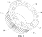
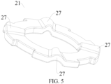
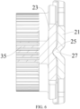
- the clutch unit includes: a first engaging portion 21 and a second engaging portion 23. End surfaces of the first engaging portion 21 and the second engaging portion 23 are opposed to each other. One of the two end surfaces of the first engaging portion 21 and the second engaging portion 23 facing each other has a plurality of locking slots 25, and the other of the two end surfaces of the first engaging portion 21 and the second engaging portion 23 facing each other has at least one locking protrusion 27.
- the locking slot 25 is disposed on the end surface of the first engaging portion 21, and the locking protrusion 27 is disposed on the end surface of the second engaging portion 23.
- the locking slot 25 is disposed on the end surface of the second engaging portion 23, and the locking protrusion 27 is disposed on the end surface of the first engaging portion 21.
- Each of the locking protrusions 27 is adapted to be engaged with at least two of the locking slots 25 so that the second engaging portion 23 and the first engaging portion 21 are adapted to be engaged at least two engaging positions in the circumferential direction.
- the first engaging portion 21 and the second engaging portion 23 both may be annular. One end surface of the first engaging portion 21 and one end surface of the second engaging portion 23 are opposite to each other.
- An oil groove 24 is disposed on the end surface of one of the first engaging portion 21 and the second engaging portion 23.
- the oil groove 24 is configured to store lubricating oil to reduce a friction.
- the oil groove 24 is disposed on the end surface of one of the first engaging portion 21 and the second engaging portion 23 on which the locking slot 25 is provided. There may be a plurality of oil grooves 24. A plurality of oil grooves 24 are provided between two adjacent locking slots 25.
- One of the two end surfaces of the first engaging portion 21 and the second engaging portion 23 facing each other has a plurality of locking slots 25, and the other has at least one locking protrusion 27. At least a part of the locking protrusion 27 protrudes into the locking slot 25.
- the locking protrusion 27 is engaged with the locking slot 25, so that the first engaging portion 21 and the second engaging portion 23 are engaged.
- the locking slot 25 is disposed on the end surface of the first engaging portion 21, and the locking protrusion 27 is disposed on the end surface of the second engaging portion 23.
- the locking slot 25 is disposed on the end surface of the second engaging portion 23, and the locking protrusion 27 is disposed on the end surface of the first engaging portion 21.
- the locking protrusion 27 is disposed on the end surface of the first engaging portion 21, and the locking slot 25 is disposed on the end surface of the second engaging portion 23, for example.
- the first engaging portion 21 may be splined or formed integrally with the rotating turntable 13 described in the above embodiments.
- the end surface of the first engaging portion 21 is configured such that the rotating turntable 13 faces the end surface of the second engaging portion 23.
- the locking protrusion 27 is formed on the end surface, that is, a turntable surface of the first engaging portion 21 is omitted. In this way, the entire actuator 100 has a small weight.
- the locking protrusion 27 may be integrally formed on the end surface of the rotating turntable 13 facing the second engaging portion 23, or the locking protrusion 27 may be detachably connected to the rotating turntable 13, so that the rotating turntable 13 has a simpler structure and is more easily formed.
- the plurality of locking slots 25 are evenly spaced and arranged along a circumferential direction of the second engaging portion 23, and the plurality of locking protrusions 27 are evenly spaced and arranged along a circumferential direction of the first engaging portion 21.
- an included angle between center lines of two adjacent locking slots 25 is 90° without consideration of a processing error.
- the plurality of locking protrusions 27 are engaged with the plurality of locking slots 25 in one-to-one correspondence.
- Each of the locking protrusions 27 is adapted to be engaged with at least two of the locking slots 25 so that the second engaging portion 23 and the first engaging portion 21 are adapted to be engaged at least two engaging positions.
- the locking protrusion 27 may be engaged with two locking slots 25, and an angle between center lines of the two locking slots 25 represents an angle by which the first engaging portion 21 and the second engaging portion 23 rotate relative to each other.
- each group includes a plurality of locking slots 25. Different groups of locking slots 25 are alternately disposed in the circumferential direction.
- the plurality of locking protrusions 27 are in one-to-one correspondences with one group of the plurality of locking slots 25.
- the plurality of locking protrusions 27 are in one-to-one correspondences with another group of the plurality of locking slots 25.
- An included angle between center lines of two locking slots 25 corresponding to each other in the two groups of locking slots 25 is 90°.
- a number of groups of the locking slots 25 may correspond to a number of positions of the display terminal 200.
- the display terminal 200 includes two positions: a landscape mode and a portrait mode
- Each group includes three locking slots 25 evenly spaced in the circumferential direction.
- the two groups of locking slots 25 are alternately disposed in the circumferential direction.
- one locking slot 25 in a second group is disposed on both sides of each locking slot 25 in the first group, so that during each rotation, each locking protrusion 27 only needs to be inserted from one locking slot 25 into another locking slot 25, and does not fall into a non-target locking slot 25 during rotation.
- An included angle between a center line of the locking slot 25 in the first group and a center line of one of the two locking slots 25 in the second group is 90°, and an included angle between the center line of the locking slot 25 in the first group and a center line of the other of the two locking slots 25 in the second group is 30°.
- the locking slot 25 and the locking protrusion 27 both have an arc-shaped cross section.
- a width of a root of the locking protrusion 27 is greater than a width of a top end of the locking protrusion 27, a width of an open end of the locking slot 25 is greater than a width of a bottom of the locking slot 25, and a width of the locking protrusion 27 gradually decreases from the root to the top end.
- the first engaging portion 21 and the second engaging portion 23 can be disengaged through relative sliding of the arc-shaped surfaces when receiving a large torque, and therefore are unlikely to be stuck.
- the arc-shaped locking protrusion 27 slides along the end surface of the second engaging portion 23. Since a friction between the first engaging portion 21 and the second engaging portion 23 is reduced, the first engaging portion and the second engaging portion can quickly slide to a next engaging position, and are unlikely to be stuck.
- the locking slot 25 and the locking protrusion 27 both are an annular sector concentric with the first engaging portion 21 or the second engaging portion 23.
- the locking slot 25 and the locking protrusion 27 both have a sector-annular cross section concentric with the first engaging portion 21 or the second engaging portion 23.
- a width of the locking slot 25 and the width of the locking protrusion 27 gradually increase from inside to outside along the radial direction. It may be understood that when a torque is being transmitted between the first engaging portion 21 and the second engaging portion 23, an outer end of the locking slot 25 and an outer end of the locking protrusion 27 receive a large moment.
- force-receiving areas of the outer end of the locking slot 25 and the outer end of the locking protrusion 27 can be increased, pressure on the outer end of the locking slot 25 and the outer end of the locking protrusion 27 can be reduced, and strength of the outer end of the locking slot 25 and the outer end of the locking protrusion 27 can be enhanced, thereby avoiding breakage.
- the outer end refers to an end of the locking slot 25 and the locking protrusion 27 facing away from an axis of the first engaging portion 21 or the second engaging portion 23.
- a width of at least a part of the locking protrusion 27 is greater than the width of the open end of the locking slot 25, and at least one side of the locking protrusion 27 is pressed against a corresponding side of the locking slot 25 so that the locking protrusion 27 is engaged with the locking slot 25.
- each locking protrusion 27 is engaged with a corresponding locking slot 25, and when there is a specific error between an actual rotation angle of the display terminal 200 and a design angle, each locking protrusion 27 remains engaged with the corresponding locking slot 25, preventing a part of the locking protrusion 27 from being falsely engaged with the corresponding locking slot 25.
- the false engagement means that the locking protrusion 27 protrudes into the corresponding locking slot 25, but is not pressed against a wall surface of the locking slot 25.
- the width of the locking slot 25 gradually decreases from the open end to the bottom, the width of the locking protrusion 27 gradually decreases from the root to the top, and the width of the open end of the locking slot 25 is less than the width of the root of the locking protrusion 27.
- a central angle of an annular sector at the open end of the locking slot 25 is less than a central angle of an annular sector at the root of the locking protrusion 27 when the first engaging portion 21 and the second engaging portion 23 are engaged.
- each locking protrusion 27 is engaged with a corresponding locking slot 25, and when there is a specific error between an actual rotation angle of the display terminal 200 and a design angle, each locking protrusion 27 remains engaged with the corresponding locking slot 25, preventing a part of the locking protrusion 27 from being falsely engaged with the corresponding locking slot 25.
- a part of the locking protrusion 27 is engaged with the locking slot 25, helping the locking protrusion 27 slide out of the locking slot 25 during manual operation.
- a depth of the locking slot 25 is less than a height of the locking protrusion 27, so that the second engaging portion 23 has larger strength.
- the first engaging portion 21 and the second engaging portion 23 both may be annular.
- One end surface of the first engaging portion 21 and one end surface of the second engaging portion 23 are opposite to each other.
- An oil groove 24 is disposed on the end surface of one of the first engaging portion 21 and the second engaging portion 23. The oil groove 24 is configured to store lubricating oil to reduce a friction.
- One of the two end surfaces of the first engaging portion 21 and the second engaging portion 23 facing each other has a plurality of locking slots 25, and the other has at least one locking protrusion 27. At least a part of the locking protrusion 27 protrudes into the locking slot 25. When a side surface of the locking protrusion 27 is pressed against a side wall of the locking slot 25, the locking protrusion 27 is engaged with the locking slot 25, so that the first engaging portion 21 and the second engaging portion 23 are engaged.
- Each of the locking protrusions 27 is adapted to be engaged with at least two of the locking slots 25 so that the second engaging portion 23 and the first engaging portion 21 are adapted to be engaged at least two engaging positions.
- the locking protrusion 27 may be engaged with two locking slots 25, and an angle between center lines of the two locking slots 25 represents an angle by which the first engaging portion 21 and the second engaging portion 23 rotate relative to each other.
- the locking slot 25 is disposed on the end surface of the first engaging portion 21, and the locking protrusion 27 is disposed on the end surface of the second engaging portion 23.
- the locking slot 25 is disposed on the end surface of the second engaging portion 23, and the locking protrusion 27 is disposed on the end surface of the first engaging portion 21.
- the locking protrusion 27 is disposed on the end surface of the first engaging portion 21, and the locking slot 25 is disposed on the end surface of the second engaging portion 23, for example.
- each group includes a plurality of locking slots 25. Different groups of locking slots 25 are alternately disposed in the circumferential direction.
- the plurality of locking protrusions 27 are in one-to-one correspondences with one group of the plurality of locking slots 25.
- the plurality of locking protrusions 27 are in one-to-one correspondences with another group of the plurality of locking slots 25.
- An included angle between center lines of two locking slots 25 corresponding to each other in the two groups of locking slots 25 is 90°.
- a number of groups of the locking slots 25 may correspond to a number of positions of the display terminal 200. For example, when the display terminal 200 includes two positions: a landscape mode and a portrait mode, there are two groups of locking slots 25. For example, there are two groups of locking slots 25. Each group includes three locking slots 25 evenly spaced in the circumferential direction. The two groups of locking slots 25 are alternately disposed in the circumferential direction. For example, one locking slot 25 in a second group is disposed on both sides of each locking slot 25 in the first group.
- An included angle between a center line of the locking slot 25 in the first group and one of center lines of the two locking slots 25 in the second group is 90°, and an included angle between the center line of the locking slot 25 in the first group and the other of the center lines of the two locking slots 25 in the second group is 30°.
- the locking slot 25 and the locking protrusion 27 both have an arc-shaped cross section.
- a width of a root of the locking protrusion 27 is greater than a width of a top end of the locking protrusion 27, a width of an open end of the locking slot 25 is greater than a width of a bottom of the locking slot 25, and a width of the locking protrusion 27 gradually decreases from the root to the top end.
- the locking slot 25 and the locking protrusion 27 are in clearance fit in the circumferential direction, that is, a width of the locking slot 25 in the circumferential direction is greater than a width of the locking protrusion 27 in the circumferential direction, a depth of the locking slot 25 is greater than a depth of the locking protrusion 27, and the width of the open end of the locking slot 25 is greater than the width of the root of the locking protrusion 27.
- One side of the locking protrusion 27 is pressed against one side of the locking slot 25 so that the locking protrusion 27 and the locking slot 25 are engaged. In this way, the same sides of the plurality of locking protrusions 27 in the circumferential direction are pressed against one side wall of a corresponding locking slot 25 so that of the first engaging portion 21 and the second engaging portion 23 are engaged.
- the first engaging portion 21 and the second engaging portion 23 can be disengaged through relative sliding of the arc-shaped surfaces when receiving a large torque.
- a friction between the first engaging portion 21 and the second engaging portion 23 is reduced, so that the first engaging portion and the second engaging portion can quickly slide to a next engaging position, and are unlikely to be stuck.
- the locking slot 25 and the locking protrusion 27 both are an annular sector concentric with the first engaging portion 21 or the second engaging portion 23.
- the locking slot 25 and the locking protrusion 27 both have a sector-annular cross section concentric with the first engaging portion 21 or the second engaging portion 23.
- a width of the locking slot 25 and the width of the locking protrusion 27 gradually increase from inside to outside along the radial direction. It may be understood that when a torque is being transmitted between the first engaging portion 21 and the second engaging portion 23, the outer end receives a large moment.
- the above structure can increase strength of the outer end, preventing breakage.
- the target angle may be 90°
- the display terminal 200 is switched between a landscape mode and a portrait mode
- a matching positioning mechanism is disposed between a part fixedly connected to a vehicle body and a rotating part, for example, a matching positioning mechanism is disposed on the housing of the drive unit 30 and the rotating turntable 13, so that the display terminal 200 is rotated to the target angle.
- Two types of positioning mechanisms are described below.
- the positioning mechanism includes a limiting stop 38 and a positioning pin (not shown).
- two limiting stops 38 are disposed on the housing of the drive unit 30.
- the two limiting stops 38 are spaced apart along a circumference direction of the housing of the drive unit 30.
- An angle between the two limiting stops 38 is the target rotation angle, for example, 90°.
- a positioning pin is disposed on the rotating turntable 13. The positioning pin protrudes toward the housing of the drive unit 30, and is adapted to be pressed against the limiting stop 38. At an initial position, the positioning pin is pressed against a limiting stop 38.
- the rotating turntable 13 and the positioning pin are also rotated until the positioning pin is pressed against another limiting stop 38.
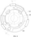
- the positioning mechanism includes a limiting slot 14 and a positioning pin (not shown).
- a limiting slot 14 As shown in FIG. 8 , an arc-shaped limiting slot 14 is disposed on the rotating turntable 13, and a positioning pin is mounted on the drive unit 30. The positioning pin protrudes toward the limiting slot 14, and may slide in the limiting slot 14. A radian of the limiting slot 14 is equal to the target rotation angle of the display terminal 200. The positioning pin is adapted to be pressed against an end of the limiting slot 14.
- the positioning pin When the positioning pin is rotated from one end of the limiting slot 14 to the other end, it indicates that the display terminal 200 is rotated into position to match the locking slots 25 and the locking protrusions 27 of the first engaging portion 21 and the second engaging portion 23, so that it can be ensured that the first engaging portion 21 and the second engaging portion 23 are always engaged.
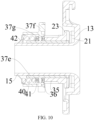
- the actuator 100 further includes: an elastic member 40 elastically pressed between the mounting unit and the drive unit 30 along the axial direction of the clutch unit, so that the drive unit 30, the clutch unit, and the mounting unit are pressed in sequence, an elastic pre-tension force (that is, the above axial pre-tension force) of the elastic member 40 is configured to engage the second engaging portion 23 with the first engaging portion 21.
- the elastic member 40 may be a spring.
- a torque is applied to the first engaging portion 21.
- the display terminal 200 is manually rotated, so that a torque is generated between the first engaging portion 21 and the second engaging portion 23.
- the torque is greater than the above opening force
- the locking protrusion 27 is gradually detached from the locking slot 25.
- the second engaging portion 23 and the drive unit 30 do not move relative to the whole vehicle in the axial direction
- the elastic member 40 is compressed, the first engaging portion 21 moves away from the second engaging portion 23 in the axial direction, and the display terminal 200 also moves away from the second engaging portion 23 in the axial direction, that is, the display terminal 200 moves rearward (a rear of the vehicle).
- the elastic member 40 may be sleeved on the mounting shaft 15, and an axial limiting member 42 is fixed on the mounting shaft 15.
- the axial limiting member 42 may be a snap ring.
- One end of the elastic member 40 is pressed against the axial limiting member 42, and the other end of the elastic member 40 is pressed against the drive unit 30.
- An axial fixed connection between the axial limiting member 42, the mounting shaft 15, and the rotating turntable 13 limits an axial length of a system. In this way, specific positive pressure can be maintained between the components connected in series (the pressure is provided by the elastic member 40 through compressed deformation).
- the components connected in series include: a rotating turntable 13 and a clutch unit to implement a locking function of the system. All of the components are also axially limited herein.
- the other end of the elastic member 40 is pressed against the housing of the drive unit 30 through an elastic member end bearing 41.
- the elastic member end bearing 41 may be a thrust bearing. Therefore, when the display terminal 200 rotates, the housing of the drive unit 30 does not move, and the mounting shaft 15 rotates.
- the elastic member end bearing 41 can significantly reduce a friction between the elastic member 40 and the housing of the drive unit 30.
- the housing of the drive unit 30 has an axial limiting portion 37g.
- An annular mounting slot is formed at the axial limiting portion 37g.
- the elastic member end bearing 41 is mounted in the mounting slot and is pressed against one side surface (a bottom wall of the mounting slot) of the axial limiting portion 37g.
- a part of the elastic member 40 is also located in the mounting slot, so that the entire actuator 100 has a short axial length.
- the first groove 13a and the second groove 13b of the rotating turntable and the cavity structure 11a of the mounting bracket 11 are also combined with the mounting slot, so that a layout of the whole mechanism is more compact and proper and a connection is tighter.
- a method for obtaining the positive pressure may also be limiting by using an axial limiting portion 37g at one end and riveting or tightening by using a rand or a nut at one end.
- a structure of the drive unit 30 of the actuator 100 in this embodiment of the present disclosure is described below.
- the drive unit 30 includes: a power source 31 and a speed reducer.
- An output shaft of the drive unit may be an output shaft 31a of the power source 31 or an output end of the speed reducer.
- the output shaft 31a of the power source 31 is connected to an input end of the speed reducer, and an output end of the speed reducer is connected to the mounting unit, or is connected to the second engaging portion 23.
- the mounting unit is driven through the second engaging portion 23 and the first engaging portion 21.
- the power source 31 may be a motor, an oil pump, an air pump, etc.
- the speed reducer may be a gear reducer or a belt drive reducer, or may be a worm gear transmission mechanism, etc.
- the speed reducer may be a one-stage reducer mechanism or a multi-stage reducer mechanism.
- the drive unit 30 for driving movement of the display terminal includes: a power source 31 and a speed reducer.
- the speed reducer includes a driving worm and a driven spur gear.
- the driving worm is connected to an output shaft 31a of the power source 31, and the driven spur gear is engaged with the driving worm.
- the worm-spur gear reducer mechanism is compact, small in size, light in weight, stable in transmission, and low in noise.
- the entire reducer mechanism has a flexible layout, facilitates wiring, more meets requirements of a compact vehicle structure and a limited vehicle weight, and also provides users with better driving experience.
- the output shaft 31a of the power source 31 and the driving worm of the speed reducer may be detachably connected through a coupler.
- the driving worm is pivotally mounted on the housing of the drive unit 30, and is positioned to match the housing of the drive unit 30 in an axial direction of the driving worm. In other words, the driving worm cannot move relative to the housing of the drive unit 30 in the axial direction (without consideration of an assembling gap).
- the power source 31 outputs a rotational speed to the driving worm through the coupler.
- the power source 31 needs to be disassembled through merely the coupler. Since the driving worm is axially positioned on the housing of the drive unit 30, when the power source 31 is disassembled, engagement between the driving worm and a gear in the speed reducer is not affected.
- the power source 31 and the speed reducer may be mounted and fixed separately, so that impact of vibration of the power source 31 on the components in the speed reducer can be weakened, preventing the driving worm from swinging.
- the coupler is disposed, so that engagement stability of the components in the speed reducer can be improved and a life of the drive unit 30 can be increased, and the power source 31 can be inspected and repaired alone without affecting engagement between the worm and the gear.
- the coupler includes: a first sub-coupler 39a and a second sub-coupler 39b.
- the first sub-coupler 39a is fixedly connected to the output shaft 31a of the power source 31
- the second sub-coupler 39b is fixedly connected to the driving worm
- the second sub-coupler 39b is detachably connected to the first sub-coupler 39a.
- the first sub-coupler 39a and the second sub-coupler 39b approach each other along an axial direction for assembling.
- the first sub-coupler 39a and the second sub-coupler 39b are fixed along a circumferential direction so as to be able to transmit a torque.
- the first sub-coupler 39a and the second sub-coupler 39b move away from each other along the axial direction for disassembling, so that the driving worm is not affected during the disassembling.
- the first sub-coupler 39a and the second sub-coupler 39b are engaged by using inserting teeth.
- a plurality of inserting teeth are disposed on the first sub-coupler 39a, and a plurality of inserting slots are disposed on the second sub-coupler 39b.
- the inserting teeth are in one-to-one correspondences with the inserting slots. During disassembling, merely the inserting teeth need to be disengaged from the inserting slots for disassembling the first sub-coupler 39a and the second sub-coupler 39b.
- An axial limiting support structure is disposed on housing of the drive unit 30.
- the driving worm is supported by the axial limiting support structure, and a shaft shoulder of the driving worm is opposite to an end surface of the axial limiting support structure to achieve axial positioning.
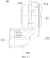
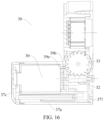
- the housing of the drive unit 30 includes: a housing body 37a, a front housing cover 37f, and a rear housing cover 37c.
- the housing body 37a defines a first cavity 37k and a second cavity 37m.
- the first cavity 37k and the second cavity 37m are isolated by a partition 37h.
- the power source 31 is mounted in the first cavity 37k
- the driving worm is mounted in the second cavity 37m.
- An avoidance hole 37j is disposed on the partition 37h.
- the driving worm protrudes into the first cavity 37k through the avoidance hole 37j and is detachably connected to the output shaft 31a of the power source 31.
- An axial limiting support structure may be disposed on the partition 37h at the avoidance hole 37j.
- the partition 37h is configured to obtain two mounting cavities, and can axially limit the driving worm to prevent the driving worm from shaking during disassembling of the power source 31.
- the rear housing cover 37c is connected to the housing body 37a to cover the open end of the first cavity 37k
- the front housing cover 37f is connected to the housing body 37a to cover an open end of the second cavity 37m.
- the coupler is mounted in the first cavity 37k, and a shaft sleeve 37n is disposed on the front housing cover 37f.
- the driving worm is supported in the shaft sleeve 37n, and the shaft shoulder of the driving worm is opposite to an end surface of the shaft sleeve 37n.
- the rear housing cover 37c is disassembled, and the power source 31 and the first sub-coupler 39a are disassembled from the second sub-coupler 39b as a whole.
- the engagement between the driving worm and the driven spur gear is not affected, so that tooth breaking can be avoided during subsequent use.
- An included angle between an axis of the driving worm and an axis of the driven spur gear is an acute angle.
- the included acute angle between the axis of the driving worm and the axis of the driven spur gear is ⁇ , which satisfies the following: 82° ⁇ ⁇ ⁇ 88° .
- 84° ⁇ ⁇ ⁇ 86° is a value of ⁇ is determined according to a helix angle of the driving worm.
- the driving worm and the driven spur gear are not perpendicular to each other, so that it can be ensured that the driving worm and the driven spur gear are well engaged and that transmission efficiency is higher.
- the spur gear is easily processed.
- Gear-worm transmission in the related art is improved to gear-spur gear transmission, so as to avoid poor processing performance of a gear.
- the speed reducer is a one-stage transmission mechanism, and includes: a first-stage driving worm and a first-stage driven spur gear.
- the first-stage driving worm is connected to the output shaft 31a of the power source 31.
- the output shaft 31a of the power source 31 and the first-stage driving worm may be fixedly connected, or may be detachably connected through a coupler.
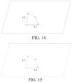
- the first-stage driving worm is engaged with the first-stage driven spur gear, and an included angle between an axis of the first-stage driving worm and an axis of the first-stage driven spur gear is an acute angle. As shown in FIG.
- the axis L1 of the first-stage driving worm and the axis L2 of the first-stage driven spur gear are projected onto a projection plane parallel to the two axes, to obtain an included angle ⁇ between the axis of the first-stage driving worm and the axis of the first-stage driven spur gear, which satisfies the following: 82° ⁇ ⁇ ⁇ 88° .
- 84° ⁇ ⁇ ⁇ 86° .
- ⁇ 85° .
- a value of ⁇ is determined according to a helix angle of the first-stage driving worm.
- the first-stage driving worm and the first-stage driven spur gear are not perpendicular to each other, so that it can be ensured that the first-stage driving worm and the first-stage driven spur gear are well engaged and that transmission efficiency is higher.
- the spur gear is easily processed.
- Gear-worm transmission in the related art is improved to gear-spur gear transmission, so as to avoid poor processing performance of a gear.
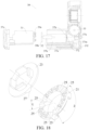
- the speed reducer is a second-stage transmission mechanism, and includes: a first-stage driving worm 32, a first-stage driven spur gear 33, a second-stage driving worm 34, and a second-stage driven spur gear 35.
- An output end of the speed reducer may be the second-stage driven spur gear 35.
- the output shaft 31a of the power source 31 is connected to the first-stage driving worm 32, and the first-stage driving worm 32 may be integrated outside the output shaft 31a of the power source 31.
- the output shaft 31a of the power source 31 and the first-stage driving worm may be fixedly connected, or may be detachably connected through a coupler.
- the first-stage driving worm 32 is engaged with the first-stage driven spur gear 33, and an included angle between an axis of the first-stage driving worm 32 and an axis of the first-stage driven spur gear 33 is an acute angle.
- the axis L1 of the first-stage driving worm and the axis L2 of the first-stage driven spur gear are projected onto a projection plane parallel to the two axes, to obtain an included angle ⁇ between the axis of the first-stage driving worm 32 and the axis of the driven spur gear 33, which satisfies the following: 82° ⁇ ⁇ ⁇ 88° .
- a value of ⁇ is determined according to a helix angle of the first-stage driving worm 32.
- the first-stage driving worm 32 and the first-stage driven spur gear 33 are not perpendicular to each other, so that it can be ensured that the first-stage driving worm 32 and the first-stage driven spur gear 33 are well engaged and that transmission efficiency is higher.
- the spur gear is easily processed.
- Gear-worm transmission in the related art is improved to gear-spur gear transmission, so as to avoid poor processing performance of a gear.
- the second-stage driving worm 34 and the first-stage driven spur gear 33 are coaxially disposed, and the second-stage driving worm 34 and the first-stage driven spur gear 33 are axially spaced apart.
- the second-stage driving worm 34 and the first-stage driven spur gear 33 may be integrally processed, or the first-stage driven spur gear 33 may be connected to the second-stage driving worm 34 through a spline.
- the second-stage driven spur gear 35 is engaged with the second-stage driving worm 34, and the second-stage driven spur gear 35 is configured to output a drive force of the drive unit 30.
- An included angle between an axis of the second-stage driving worm 34 and an axis of the second-stage driven spur gear 35 is an acute angle.
- the axis L3 of the second-stage driving worm 34 and the axis L4 of the second-stage driven spur gear 35 are projected onto a projection plane parallel to the two axes, to obtain an included angle ⁇ between the axis of the second-stage driving worm 34 and the axis of the second-stage driven spur gear 35, which satisfies the following: 82° ⁇ ⁇ ⁇ 88° .
- ⁇ 85° .
- a value of ⁇ is determined according to a helix angle of the second-stage driving worm 34.
- the second-stage driving worm 34 and the second-stage driven spur gear 35 are not perpendicular to each other, so that it can be ensured that the second-stage driving worm 34 and the second-stage driven spur gear 35 are well engaged and that transmission efficiency is higher.
- the spur gear is easily processed. Gear-worm transmission in the related art is improved to gear-spur gear transmission, so as to avoid poor processing performance of a gear.
- the axis of the first-stage driving worm 32, the axis of the second-stage driven spur gear 35, and the axis of the clutch unit are parallel.
- An axis of the output shaft 31a of the power source 31 and the axis of the second-stage driven spur gear 35 are parallel and spaced apart. In this way, an arrangement direction of the power source 31 can be parallel to an output direction of the drive unit 30, facilitating assembly designing.
- a self-locking function of the worm self-locking can be triggered when the helix angle of the worm is less than a friction angle
- a clutch function of the whole solution can be achieved, that is, during manual operation, the speed reducer is self-locked, so that the second engaging portion 23 is fixed, and the first engaging portion 21 can perform relative rotation.
- the worm-spur gear reducer mechanism is compact, small in size, light in weight, stable in transmission, and low in noise.
- the entire reducer mechanism has a flexible layout, facilitates wiring, more meets requirements of a compact vehicle structure and a limited vehicle weight, and also provides users with better driving experience.
- the first-stage driven spur gear 33 transmits high-speed rotation of the first-stage driving worm 32 to the second-stage driving worm 34.
- the first-stage driven spur gear 33 may be a plastic member, and the first-stage driving worm 32, the second-stage driving worm 34, and the second-stage driven spur gear 35 are metal members.
- the second-stage driven spur gear 35 is connected to the second engaging portion 23 to achieve power output.
- the second-stage driven spur gear 35 is integrated with the second engaging portion 23.
- the second-stage driven spur gear 35 and the second engaging portion 23 may be made of different materials.
- the second-stage driven spur gear 35 is made of wear-resistant materials, and the second engaging portion 23 is made of self-lubricating materials, such as polyoxymethylene, molybdenum disulfide, or boron nitride, etc.
- the drive unit 30 may further include: an output interface connected to the second-stage driven spur gear 35.
- the output interface is configured to output a drive force, and the output interface may be the second engaging portion 23 of the clutch unit.
- the output interface and the second-stage driven spur gear 35 both are hollow rings.
- Hollow shapes of the first engaging portion 21, the second engaging portion 23, and the second-stage driven spur gear 35 are used for facilitating wiring and reducing a weight.
- a torque input end and a torque output end are not on the same axis.
- a hollow shaft and a transmission system can cause an input shaft and an output shaft to be parallel shaft directions, facilitating spatial planning of the structure and providing a larger design margin.
- the first-stage driving worm 32 is fixedly connected to a motor shaft. One end protrudes from the motor and the other end is restricted by the housing structure.
- the first-stage driven spur gear 33 and the second-stage driving worm 34 are fixed on the same shaft. Due to a limited space, shaft sleeves with shoulders are used at two ends instead of bearings.
- the shaft sleeve has lubricating oil inside.
- the second-stage driven spur gear 35 is also limited by the housing structure. One end is integrated with the output structure, and the other end is born by an end bearing. Both the sleeve and the end bearing reduce friction losses during rotation and reduce the generated frictional heat.
- the second-stage driven spur gear 35 may be a hollow gear, not only reducing a weight of the entire drive unit 30, but also facilitating assembling.
- the housing of the drive unit 30 includes: a housing body 37a, a rear housing cover 37c, an upper housing cover 37d, and a front housing cover 37f.
- All of the power source 31, the first-stage driving worm 32, the first-stage driven spur gear 33, and the second-stage driving worm 34 are mounted on the housing body 37a, the second-stage driven spur gear 35 is mounted on the upper housing cover 37d, the first-stage driven spur gear 33 and the second-stage driving worm 34 are fixed on the same shaft, and the first-stage driven spur gear 33 and the second-stage driving worm 34 are coaxially disposed.
- the housing body 37a is a plastic member
- the upper housing cover 37d is a metal member. It may be understood that the housing body 37a mainly bears high-speed components, and the plastic members facilitate shock absorption.
- the upper housing cover 37d mainly bears low-speed components and is formed integrally.
- the housing body 37a and the upper housing cover 37d are integrally formed.
- the rear housing cover 37c is connected to the housing body 37a to cover a rear end of the housing body 37a.
- the upper housing cover 37d is connected to the housing body 37a
- the front housing cover 37f is connected to the housing body 37a to cover a front end of the housing body 37a.
- the rear housing cover 37c, the upper housing cover 37d, the front housing cover 37f, and the housing body 37a may be connected by using a buckling structure and a threaded fastener.
- the housing receives an impact load, and the second engaging portion 23 receives axial positive pressure and a circumferential torque during rotation, which are transmitted to the housing. Therefore, in order to guarantee stability of the drive unit 30, in addition to screwing and buckling connections between the components, the drive unit 30 is fastened to the base 50 in the actuator 100 by using screws, so as to increase the strength and a service life of the drive unit 30.
- the housing of the drive unit 30 has an axial limiting portion. An end surface of the second-stage driven spur gear 35 facing away from the display terminal 200 is pressed against the axial limiting portion, and an end surface of the second-stage driven spur gear 35 facing away from the second engaging portion 23 is pressed against the axial limiting portion.
- the upper housing cover 37d may have an axial limiting portion 37g for limiting the end surface of the second-stage driven spur gear 35, so that an end surface of the second-stage driven spur gear 35 is connected to the second engaging portion 23, and another end surface of the second-stage driven spur gear 35 is pressed against the upper housing cover 37d, thereby guaranteeing axial positioning of the second-stage driven spur gear 35 and avoiding tooth breaking of the second-stage driven spur gear 35 and the second-stage driving worm 34.
- the second-stage driven spur gear 35 is pressed against the axial limiting portion 37g through a gear end bearing 36.
- the gear end bearing 36 may be a thrust bearing. In this way, a friction between the second-stage driven spur gear 35 and the housing of the drive unit 30 can be reduced, reducing torque losses.
- an annular groove may be disposed on the upper housing cover 37d for assembling the gear end bearing 36.
- An annular groove may be disposed on the end surface of the second-stage driven spur gear 35 facing away from the second engaging portion 23.
- the gear end bearing 36 is provided in the annular groove, and is pressed against a bottom wall of the annular groove. At least a part of the axial limiting portion 37g protrudes into the annular groove. In some embodiments, a deep groove shape may be provided in the axial limiting portion 37g. An end surface of the axial limiting portion 37g is pressed against the elastic member end bearing 41, and another end surface of the axial limiting portion 37g is pressed against the gear end bearing 36.
- the gear end bearing 36 is also in the annular groove of the second-stage driven spur gear 35, and at least a part of the elastic member 40 may be located in the annular groove of the second-stage driven spur gear 35.
- the axial length of the entire mechanism can be shortened, and space is saved, so that the entire mechanism is more applicable.
- rigidity of the system is also enhanced, strengthening bending and torsion resistance of the system.
- the upper housing cover 37d has a sleeve 37e.
- the second-stage driven spur gear 35 is sleeved on the sleeve 37e, and the axial limiting portion 37g is located on an outer peripheral surface of the sleeve 37e.
- the housing of the drive unit 30 has a radial holding mechanism.
- the second engaging portion 23 is relatively rotatably disposed on the radial holding mechanism for limiting in a radial direction.
- the radial holding mechanism is configured to prevent a radial bias of at least some of the rotating components to prevent the actuator 100 from being radially biased during operation, so that the actuator 10 can still operate stably after long-term operation.
- the housing of the drive unit 30 remains stationary after being mounted on the vehicle body.
- the housing of the drive unit 30 has two hollow rings disposed in a sleeving manner: an outer ring and an inner ring.
- the radial holding mechanism includes the outer ring and the inner ring.
- the outer ring is sleeved on the inner ring, and the outer ring and the inner ring define an annular cavity.
- At least a part of the second engaging portion 23 is located in the annular cavity, and at least a part of the second engaging portion 23 is sleeved on the inner ring.
- the inner ring is configured to prevent the second engaging portion 23 from being biased radially inward.
- the outer ring is sleeved on at least a part of the second engaging portion 23, and is configured to prevent the second engaging portion 23 from being biased radially outward.
- the housing of the drive unit 30 includes: A housing body 37a, an upper housing cover 37d, and a front housing cover 37f.
- the upper housing cover 37d is connected to the housing body 37a, and has an annular sleeve 37e.
- the front housing cover 37f is connected to a front end of the housing body 37a, and has an annular limiting ring 37p.
- the limiting ring 37p is sleeved on the sleeve 37e to define an annular cavity. In other words, an inner diameter of the limiting ring 37p is greater than an inner diameter of the sleeve 37e.
- the annular cavity is located between an inner peripheral wall of the limiting ring 37p and an outer peripheral wall of the sleeve 37e. At least a part of the second engaging portion 23 is provided in the annular cavity. At least a part of the second engaging portion 23 is sleeved on the sleeve 37e. The sleeve 37e is configured to prevent the second engaging portion 23 from being biased radially inward. The limiting ring 37p is sleeved on at least a part of the second engaging portion 23, and is configured to prevent the second engaging portion 23 from being biased radially outward.
- An output end of the drive unit 30 includes an annular output gear.
- the output gear may be the second-stage driven spur gear 35 in the above embodiment.
- the output gear is connected to the second engaging portion 23, and the output gear is sleeved on the sleeve 37e.
- the second engaging portion 23 includes an engaging pad 28 to be locked with the first engaging portion 21 and a connecting sleeve 26 connected to an end of the engaging pad 28 facing away from the first engaging portion 21.
- the connecting sleeve 26 is connected to the output gear, and the limiting ring 37p is sleeved on the connecting sleeve 26. In this way, radial inner and outer sides of the output gear are also respectively limited by the sleeve 37e and the limiting ring 37p.
- the output end of the drive unit 30 is unlikely to be affected by external vibration during working, avoiding tooth breaking.
- the radial holding mechanism may also include a radial limiting bearing (not shown).
- a radial limiting bearing is provided between the limiting ring 37p and at least a part of the second engaging portion 23.
- a radial limiting bearing may be provided between the limiting ring 37p and the connecting sleeve 26. In this way, an inner ring of the radial limiting bearing is pressed against the connecting sleeve 26, and an outer ring of the radial limiting bearing is pressed against the limiting ring 37p, so that the radial holding mechanism is radially limited more stably.
- the mounting unit includes: a mounting shaft 15 penetrating the clutch unit and the drive unit 30.
- the sleeve 37e is sleeved on the mounting shaft 15.
- the sleeve 37e can radially limit the mounting shaft 15 at an outer side, thereby further enhancing radial stability of the rotating turntable 13.
- the drive unit 30 in this patent can adopt a planetary gear train or a two-stage worm and a spur gear transmission system, so that the system has the following advantages: 1) The system has a compact structure, a small size, and a light weight. 2) The system has stable transmission, low noise, a high transmission ratio, and an obvious deceleration effect. 3) The system has a flexible layout and facilitates wiring. The system more meets requirements of a compact vehicle structure and a limited vehicle weight, and also provides users with better driving experience.
- the dedicated in-position locking system in this patent can effectively isolate an internal transmission system of the drive unit 30 from external impact, so that not only micro-vibration and whirling of the display terminal 200 caused by an internal backlash of the transmission system is avoided, improving the stability and anti-shake and anti-vibration performance of the system, but also damage to the transmission system caused by external impact is avoided, improving reliability and a service life of the system.
- the present disclosure is mainly used for a rotating mechanism of the display terminal 200. The present disclosure is also applicable to other electronic products with rotating requirements. 6) As described above, the components are connected by using the mounting shaft 15 in the axial direction. A series of components cause error accumulation (a production error and an assembling error).
- the pitch can be eliminated to a large extent through spring compression to reduce the error.
- Other improvement measures are to shorten an axial matching size. An appropriate position is found from a movement structure, and a groove is designed to put components such as a spring into the movement, so as to shorten an axial length of the entire mechanism to reduce a dimension chain error. 7) The axial length is reduced, and the rigidity of the entire system is also increased. Therefore, when the system is loaded by an external force, a capability of resisting bending and torsion is better, and the system is unlikely to be deformed or damaged. 8) In addition, in addition to the increased stiffness, the shorter axial length also enhances the overall stability and reduces shaking. 9) This solution focuses on achieving modular designing of automatic and manual integrated rotating mechanism.
- one end of the rotating turntable 13 forms, by using an axial limiting portion 42, a retaining wall pressed against the elastic element 40, and the other end is a turntable body similar to a shaft shoulder, which together axially lock a plurality of components in the axial direction.
- the design can effectively avoid micro-vibration and whirling of the display terminal 200 caused by a backlash existing in the drive unit 30, avoiding visual staying caused therefrom, and avoid a risk of damaging the transmission system due to tooth breaking caused by the micro-vibration in vibration impact, guaranteeing anti-shake and anti-vibration performance of the system.
- the locking slot 25 is slightly larger than the locking protrusion 27 to reserve an appropriate pre-compression angle, so that incomplete buckling caused by manufacturing tolerances is avoided, requirements on the clutch unit and position accuracy are reduced, and shaking and instability of components as a result of a pitch caused by production errors can be avoided.
- An oil groove 24 is disposed on the end surface of the second engaging portion 23, greatly improving a frictional state of the first engaging portion 21 and the second engaging portion 23 during rotation relative to each other, improving service lives of the components, and improving hand feeling of a user to some extent during manual rotation.
- the first engaging portion 21 and the second engaging portion 23 are key components.
- the two components are temporarily fastened into one body, and the drive unit 30 outputs automatic power to achieve automatic rotation.
- An outstanding feature of this solution is two working modes: the manual mode and the automatic mode.
- Aproper torque threshold is designed to distinguish between the two modes.
- the key component that is, the second engaging portion 23 in the manual mode is used as the output end of the drive unit 30 to achieve coexistence of the two modes.
- the display terminal 200 in this system is rotated at an extremely small speed (about 6-10 r/min), which requires the drive unit 30 to have a relatively large transmission ratio of about 1500-2000.
- a planetary gear reducer or a double worm reducer system of a two-stage worm-spur gear may be selected according to a specific structure layout.
- An entire shaft is designed as a hollow structure, facilitating designing of the locking system.
- a current-limiting circuit board is built in the rotating system, so that when a current exceeding a specified threshold is detected, the motor is powered off, so as to achieve safety anti-pinch and overload protection.
- the display terminal 200 is at an abnormal position, and it is determined that the motor is abnormally powered off as a result of resistance.
- a warning screen appears to remind a customer to check for foreign objects.
- restart and return are performed according to selection of the customer.
- Determining of an abnormal position includes manual operation in the automatic running state.
- software functions may be defined according to customer requirements and definitions. A limiting and locking structure in this solution can fully adapt to different software function definitions at a physical level (related to control of abnormal positions).
- the hollow designs of the rotating turntable 13 and the mounting shaft 15 facilitate wiring, so that wiring behind a screen is proper and beautiful, and a wire outlet has a relatively large rounded corner, also preventing cutting.
- This system is a centering rotating system, that is, a rotation center remains unchanged during rotation. Therefore, the mounting bracket 11 with a unified interface may be used to achieve matching and compatibility between terminals of a plurality of sizes. In this way, versatility of products is improved, costs are reduced, and quality control is convenient.
- the display terminal 200 of the system is suspended in a central control, so that an instrument table is more tidy and beautiful.
- This patent relates to an actuator 100 of a display terminal 200 that can achieve manual and automatic rotation of the display terminal 200.
- the actuator 100 can implement the following functions: 1) automatically switching the display terminal 200 between a landscape mode and a portrait mode; 2) providing two rotation modes: a manual rotation mode and an automatic rotation mode to enhance user experience; 3) automatic positioning locking after rotation in place; 4) anti-shake and of the system; 5) overload protection and safety anti-pinch; and 6) matching and compatibility and strong adaptability between terminals of a plurality of sizes.
- the present disclosure further discloses a vehicle 1000.
- the vehicle 1000 in an embodiment of the present disclosure includes: a display terminal 200 and any of the above actuators 100.
- the display terminal 200 is mounted on the mounting unit of the actuator 100, and the actuator 100 is mounted on a vehicle body.
- the housing of the drive unit 30 may be mounted on the vehicle body through the base 50.
- a rotation axis of the display terminal 200 may be a direction X (a front-to-rear direction), and the display terminal 200 may be an in-vehicle display terminal, such as a display panel mounted on a dashboard.
- the display terminal 200 of the vehicle 1000 in this embodiment of the present disclosure can be used at a plurality of angles.
- the display terminal may be switched between a landscape mode and a portrait mode manually or automatically.
- An actuator for adjusting a display terminal including: a mounting unit configured to mount a display terminal; a clutch unit, a first engaging portion of the clutch unit being connected to the mounting unit, and a second engaging portion of the clutch unit being normally interlocked with the first engaging portion; and a drive unit, an output end of the drive unit being connected to the second engaging portion.
- the clutch unit is located outside a housing of the drive unit.
- At least a part of the clutch unit is located in the mounting unit.
- the mounting unit includes a rotating turntable configured to mount the display terminal and connected to the first engaging portion, an end of the rotating turntable facing the first engaging portion having a first groove, at least a part of the first engaging portion being located in the first groove.
- At least a part of the second engaging portion is located in the first groove.
- the mounting unit includes a rotating turntable configured to mount the display terminal and integrally formed with the first engaging portion.
- the housing of the drive unit has a radial holding mechanism, the second engaging portion being relatively rotatably disposed on the radial holding mechanism for limiting in a radial direction.
- the housing of the drive unit has two hollow rings disposed in a sleeving manner: an outer ring and an inner ring.
- the radial holding mechanism includes the outer ring and the inner ring.
- the outer ring and the inner ring define an annular cavity. At least a part of the second engaging portion is provided in the annular cavity.
- the housing of the drive unit includes: a housing body, an upper housing cover, and a front housing cover, the upper housing cover being connected to the housing body and having an annular sleeve, and the front housing cover being connected to a front end of the housing body and having an annular limiting ring, the limiting ring being sleeved on the sleeve to define an annular cavity, at least a part of the second engaging portion being provided in the annular cavity.
- a radial limiting bearing is provided between the limiting ring and at least the part of the second engaging portion.
- the output end of the drive unit includes an annular output gear connected to the second engaging portion and sleeved on the sleeve.
- the second engaging portion includes an engaging pad to be locked with the first engaging portion and a connecting sleeve connected to an end of the engaging pad facing away from the first engaging portion, the connecting sleeve being connected to the output gear, and the limiting ring being sleeved on the connecting sleeve.
- the mounting unit includes: a mounting shaft penetrating the clutch unit and the drive unit.
- the sleeve is sleeved on the mounting shaft.
- the first engaging portion and the second engaging portion are engaged with each other and have a plurality of engaging positions
- the mounting unit is configured to be manually rotatable to drive the first engaging portion to rotatably switch between the plurality of engaging positions relative to the second engaging portion
- the second engaging portion and the drive unit when the engaging position is changed, remain stationary relative to each other in the axial direction, and the first engaging portion moves away from the second engaging portion in the axial direction.
- a plurality of engaging positions are formed on end surfaces of the first engaging portion and the second engaging portion opposite to each other.
- the end surfaces of the first engaging portion and the second engaging portion are opposite to each other, one of the two end surfaces facing each other has a plurality of locking slots, and the other has at least one locking protrusion, each of the locking protrusions being adapted to be engaged with at least two of the locking slots so that the second engaging portion and the first engaging portion are adapted to be engaged at least at two of the engaging positions.
- the mounting unit includes a rotating turntable configured to mount the display terminal, the end surface of the first engaging portion being configured as an end surface of the rotating turntable facing the second engaging portion, and the locking protrusion being formed on the end surface of the first engaging portion.
- the locking protrusion is detachably connected to the rotating turntable.
- both the locking slot and the locking protrusion have an arc-shaped cross section.
- first engaging portion and the second engaging portion both are circular, and the locking slot and the locking protrusion both are an annular sector concentric with the first engaging portion or the second engaging portion.
- At least one side of the locking protrusion is pressed against a corresponding side of the locking slot so that the locking protrusion is engaged with the locking slot.
- a width of at least a part of the locking protrusion is greater than a width of an open end of the locking slot.
- a width of the locking slot gradually decreases from the open end to a bottom, the width of the locking protrusion gradually decreases from a root to a top, and the width of the open end of the locking slot is less than a width of the root of the locking protrusion.
- a depth of the locking slot is less than a height of the locking protrusion.
- the locking slot and the locking protrusion are in clearance fit in the circumferential direction.
- the width of the open end of the locking slot is greater than the width of the root of the locking protrusion.
- the depth of the locking slot is greater than the height of the locking protrusion.
- there are a plurality of groups of locking slots different groups of locking slots being alternately disposed in the circumferential direction, and when the first engaging portion and the second engaging portion are engaged at one of the engaging positions, the locking protrusions being in one-to-one correspondences with one group of locking slots.
- an included angle between axes of two locking slots corresponding to each other in the two groups of locking slots is 90°.
- the actuator further includes: an elastic member elastically pressed between the mounting unit and the drive unit along an axial direction of the clutch unit, so that the drive unit, the clutch unit, and the mounting unit are pressed in sequence, an elastic pre-tension force of the elastic member being used to engage the second engaging portion with the first engaging portion.
- the mounting unit includes: a mounting bracket, a rotating turntable, and a mounting shaft, the mounting bracket being connected to the rotating turntable, the rotating turntable being connected to the mounting shaft, the mounting bracket being configured to mount the display terminal, the rotating turntable being dynamically coupled to the first engaging portion, the mounting shaft penetrating the clutch unit and the drive unit, the elastic member being sleeved on the mounting shaft, one end of the elastic member being pressed against and fixed on an axial limiting member of the mounting shaft, and the other end being pressed against the housing of the drive unit.
- the other end of the elastic member is pressed against the housing of the drive unit through an elastic member end bearing.
- the mounting bracket is detachably mounted on the rotating turntable.
- the mounting shaft is integrally formed with the rotating turntable.
- the mounting shaft is a hollow shaft.
- the housing of the drive unit and the rotating turntable are provided with a matching positioning mechanism so that the display terminal is rotated by a target angle.
- the target angle is 90°.
- two limiting stops spaced apart in the circumferential direction are disposed on the housing of the drive unit, and a positioning pin protruding toward the housing of the drive unit is disposed on the rotating turntable, the positioning pin is configured to be pressed against the limiting stop.
- the positioning mechanism includes the limiting stop and the positioning pin.
- an arc-shaped limiting slot is disposed on the rotating turntable, and a positioning pin protruding toward the limiting slot is mounted on the housing of the drive unit, the positioning pin is configured to be pressed against an end of the limiting slot.
- the positioning mechanism includes the limiting slot and the positioning pin.
- the drive unit includes: a power source and a speed reducer, an output shaft of the power source being connected to an input end of the speed reducer, and an output end of the speed reducer being connected to the second engaging portion.
- the speed reducer is a one-stage or multi-stage transmission mechanism.
- the speed reducer is a worm-gear transmission mechanism.
- the speed reducer includes a driving worm connected to the power source and a driven spur gear connected to the driving worm.
- the speed reducer includes: a first-stage driving worm fixedly connected to the output shaft of the power source; and a first-stage driven spur gear engaged with the first-stage driving worm and connected to second engaging portion.
- an included angle between an axis of the first-stage driving worm and an axis of the first-stage driven spur gear is an acute angle.
- the included angle between the axis of the first-stage driving worm and the axis of the first-stage driven spur gear is ⁇ , which satisfies the following: 82° ⁇ ⁇ ⁇ 88° .
- the speed reducer includes: a first-stage driving worm fixedly connected to the output shaft of the power source; and a first-stage driven spur gear engaged with the first-stage driving worm; a second-stage driving worm coaxially disposed with the first-stage driven spur gear; and a second-stage driven spur gear engaged with the second-stage driving worm and connected to the second engaging portion.
- an included angle between an axis of the first-stage driving worm and an axis of the first-stage driven spur gear and an included angle between an axis of the second-stage driving worm and an axis of the second-stage driven spur gear both are acute angles.
- the included angle between the axis of the first-stage driving worm and the axis of the first-stage driven spur gear is ⁇
- the included angle between the axis of the second-stage driving worm and the axis of the second-stage driven spur gear is ⁇ , which satisfy the following: 82° ⁇ A ⁇ 88° and 82° ⁇ ⁇ ⁇ 88° .
- the axis of the first-stage driving worm, the axis of the second-stage driven spur gear, and the axis of the clutch unit are parallel.
- the housing of the drive unit has an axial limiting portion, an end surface of the second-stage driven spur gear facing away from the second engaging portion being pressed against the axial limiting portion.
- the first-stage driven spur gear is a plastic member
- the first-stage driving worm, the second-stage driving worm, and the second-stage driven spur gear are metal members.
- the second-stage driven spur gear is integrally formed with the second engaging portion.
- the second engaging portion is made of self-lubricating materials
- the second-stage driven spur gear is made of wear-resistant materials
- the housing of the drive unit includes: a housing body, the power source being mounted on the housing body; and an upper housing cover connected to the housing body, the second-stage driven spur gear being mounted on the housing body, and the upper housing cover having an axial limiting portion configured to limit an end surface of the second-stage driven spur gear.
- the housing body is a plastic member
- the upper housing cover is a metal member
- the second-stage driven spur gear is pressed against the axial limiting portion through a gear end bearing.
- annular groove is disposed on the end surface of the second-stage driven spur gear, the gear end bearing being provided in the annular groove and pressed against a bottom wall of the annular groove, and at least a part of the axial limiting portion protruding into the annular groove.
- the upper housing cover has a shaft sleeve, and the second-stage driven spur gear is sleeved on the shaft sleeve.
- the housing of the drive unit further includes: a rear housing cover connected to the housing to cover a rear end of the housing; and a front housing cover connected to the housing to cover a front end of the housing.
- a vehicle including: a display terminal and any of the actuators, the actuator being mounted on a vehicle body, and the display terminal being mounted on the mounting unit of the actuator.
Landscapes
- Engineering & Computer Science (AREA)
- General Engineering & Computer Science (AREA)
- Mechanical Engineering (AREA)
- Instrument Panels (AREA)
- Arrangement And Mounting Of Devices That Control Transmission Of Motive Force (AREA)
- Fittings On The Vehicle Exterior For Carrying Loads, And Devices For Holding Or Mounting Articles (AREA)
- Gear Transmission (AREA)
Applications Claiming Priority (4)
| Application Number | Priority Date | Filing Date | Title |
|---|---|---|---|
| CN201810142922.4A CN110143172B (zh) | 2018-02-11 | 2018-02-11 | 用于调节显示终端的执行机构和车辆 |
| CN201820253677.XU CN208376648U (zh) | 2018-02-11 | 2018-02-11 | 用于调节显示终端的执行机构和车辆 |
| EP19750731.2A EP3750752B1 (de) | 2018-02-11 | 2019-01-30 | Stellantrieb zur einstellung eines anzeigeendgeräts und fahrzeug |
| PCT/CN2019/074019 WO2019154234A1 (zh) | 2018-02-11 | 2019-01-30 | 用于调节显示终端的执行机构和车辆 |
Related Parent Applications (2)
| Application Number | Title | Priority Date | Filing Date |
|---|---|---|---|
| EP19750731.2A Division EP3750752B1 (de) | 2018-02-11 | 2019-01-30 | Stellantrieb zur einstellung eines anzeigeendgeräts und fahrzeug |
| EP19750731.2A Division-Into EP3750752B1 (de) | 2018-02-11 | 2019-01-30 | Stellantrieb zur einstellung eines anzeigeendgeräts und fahrzeug |
Publications (2)
| Publication Number | Publication Date |
|---|---|
| EP4353540A2 true EP4353540A2 (de) | 2024-04-17 |
| EP4353540A3 EP4353540A3 (de) | 2024-07-31 |
Family
ID=67548163
Family Applications (2)
| Application Number | Title | Priority Date | Filing Date |
|---|---|---|---|
| EP24159607.1A Pending EP4353540A3 (de) | 2018-02-11 | 2019-01-30 | Stellantrieb zur einstellung eines anzeigeendgeräts und fahrzeug |
| EP19750731.2A Active EP3750752B1 (de) | 2018-02-11 | 2019-01-30 | Stellantrieb zur einstellung eines anzeigeendgeräts und fahrzeug |
Family Applications After (1)
| Application Number | Title | Priority Date | Filing Date |
|---|---|---|---|
| EP19750731.2A Active EP3750752B1 (de) | 2018-02-11 | 2019-01-30 | Stellantrieb zur einstellung eines anzeigeendgeräts und fahrzeug |
Country Status (5)
| Country | Link |
|---|---|
| US (1) | US11661017B2 (de) |
| EP (2) | EP4353540A3 (de) |
| ES (1) | ES2983020T3 (de) |
| HU (1) | HUE067020T2 (de) |
| WO (1) | WO2019154234A1 (de) |
Families Citing this family (14)
| Publication number | Priority date | Publication date | Assignee | Title |
|---|---|---|---|---|
| NL2023038B1 (nl) * | 2019-04-30 | 2020-11-23 | Mci Mirror Controls Int Netherlands B V | Verstelinstrument |
| CN112025586A (zh) * | 2019-06-03 | 2020-12-04 | 富泰华工业(深圳)有限公司 | 旋转装置 |
| DE102020101877B3 (de) * | 2020-01-27 | 2021-05-06 | Audi Aktiengesellschaft | Anzeigevorrichtung, Kraftfahrzeug mit einer Anzeigevorrichtung, und Verfahren zum Betreiben einer Anzeigevorrichtung |
| CN112776715A (zh) * | 2021-01-13 | 2021-05-11 | 广州驰享汽车用品有限公司 | 一种房车监控系统 |
| CN113883375A (zh) * | 2021-10-08 | 2022-01-04 | 盐城生物工程高等职业技术学校 | 一种农业技术推广用信息收集设备 |
| CN114578904A (zh) * | 2022-02-28 | 2022-06-03 | 联想(北京)有限公司 | 电子设备 |
| CN114776970B (zh) * | 2022-03-11 | 2023-11-10 | 国网河北省电力有限公司邯郸供电分公司 | 一种角度调节装置及变电站智能故障排查装置 |
| CN217672432U (zh) | 2022-04-12 | 2022-10-28 | 富泰京精密电子(烟台)有限公司 | 一种自动旋转屏幕 |
| CN115143240A (zh) * | 2022-07-29 | 2022-10-04 | 深圳市恒希电器有限公司 | 一种齿轮箱旋转机构 |
| CN116221574B (zh) * | 2023-03-23 | 2023-08-29 | 山东佰通建设工程有限公司 | 一种土地测绘用水准仪及使用方法 |
| CZ2023214A3 (cs) * | 2023-05-26 | 2024-12-04 | Ĺ KODA AUTO a.s. | Sestava displeje do palubní desky vozidla a palubní deska s touto sestavou |
| US11892876B1 (en) * | 2023-07-20 | 2024-02-06 | Pioneer Square Brands, Inc. | Swivel platform assembly for portable electronic device stand |
| CN221293290U (zh) * | 2023-09-20 | 2024-07-09 | 富泰京精密电子(烟台)有限公司 | 屏幕支架及车载旋转屏幕 |
| CN117755212B (zh) * | 2024-02-21 | 2024-05-07 | 深圳市德智欣科技有限公司 | 一种多功能车载显示屏模组 |
Family Cites Families (23)
| Publication number | Priority date | Publication date | Assignee | Title |
|---|---|---|---|---|
| JP3008334U (ja) * | 1994-08-25 | 1995-03-14 | 株式会社村上開明堂 | 電動格納式ドアミラーの減速機構 |
| DE19833514B4 (de) * | 1997-07-30 | 2005-04-28 | Buhler Motor Gmbh | Antrieb zum Abklappen eines Kraftfahrzeugrückblickspiegels |
| NL1025524C2 (nl) * | 2004-02-19 | 2005-08-22 | Iku Holding Montfoort Bv | Spiegelverstelmechanisme, buitenspiegeleenheid en werkwijze. |
| KR100565686B1 (ko) * | 2004-08-12 | 2006-03-30 | 엘지전자 주식회사 | 영상표시장치의 스탠드 어셈블리 |
| JP4741846B2 (ja) * | 2005-01-14 | 2011-08-10 | Necディスプレイソリューションズ株式会社 | 薄型表示装置用スタンド |
| TWI333098B (en) * | 2006-03-03 | 2010-11-11 | Benq Corp | Rotatable apparatus |
| DE102006021249B3 (de) | 2006-05-04 | 2007-10-25 | Bühler Motor GmbH | 1. Außenrückblickspiegel |
| US7966904B2 (en) * | 2006-05-05 | 2011-06-28 | Questek Manufacturing Corporation | Low axial play drive system |
| US8496098B1 (en) * | 2008-12-23 | 2013-07-30 | Crh North America, Inc. | Manual seat height adjuster mechanism |
| US8870137B2 (en) * | 2011-08-29 | 2014-10-28 | Stephen R. Jacobson | Adjustable hands-free mounting apparatus for tablet PCs with expanded description of its miniature subcombinations |
| US9067541B2 (en) | 2011-10-31 | 2015-06-30 | Magna Mirrors Of America, Inc. | Exterior mirror assembly with actuator |
| US9115740B2 (en) * | 2012-10-23 | 2015-08-25 | Michael Chau-Lun CHANG | Fixer for handheld, portable, mobile device |
| DE102013201434B3 (de) | 2013-01-29 | 2014-05-28 | Mekra Lang Gmbh & Co. Kg | Elektrisch rotatorische Verstelleinheit sowie indirektes Sichtsystem für Fahrzeuge mit einer solchen Verstelleinheit |
| TWM478089U (zh) * | 2014-01-08 | 2014-05-11 | Syncmold Entpr Corp | 支撐裝置 |
| CN206475829U (zh) * | 2017-01-25 | 2017-09-08 | 深圳市创晶辉精密塑胶模具有限公司 | 车载显示屏旋转器传动装置 |
| CN106740542B (zh) | 2017-01-25 | 2023-11-14 | 比亚迪股份有限公司 | 车载显示屏旋转器传动装置 |
| CN107344530B (zh) * | 2017-04-26 | 2023-05-16 | 惠州市华阳多媒体电子有限公司 | 一种车载屏幕旋转驱动结构 |
| CN107235012B (zh) * | 2017-06-07 | 2023-03-21 | 惠州市华阳多媒体电子有限公司 | 一种车载屏幕旋转结构 |
| CN107539366A (zh) * | 2017-08-25 | 2018-01-05 | 林建民 | 一种市政道路用环保新能源车 |
| EP4617122A3 (de) * | 2018-02-11 | 2025-11-05 | BYD Company Limited | Drehmechanismus für anzeigeendgerät und fahrzeug |
| CN208376648U (zh) * | 2018-02-11 | 2019-01-15 | 比亚迪股份有限公司 | 用于调节显示终端的执行机构和车辆 |
| CN208376649U (zh) * | 2018-02-11 | 2019-01-15 | 比亚迪股份有限公司 | 用于调节显示终端的执行机构和车辆 |
| KR102564304B1 (ko) * | 2018-12-31 | 2023-08-07 | 삼성전자주식회사 | 디스플레이 장치 |
-
2019
- 2019-01-30 EP EP24159607.1A patent/EP4353540A3/de active Pending
- 2019-01-30 WO PCT/CN2019/074019 patent/WO2019154234A1/zh not_active Ceased
- 2019-01-30 US US16/968,851 patent/US11661017B2/en active Active
- 2019-01-30 ES ES19750731T patent/ES2983020T3/es active Active
- 2019-01-30 EP EP19750731.2A patent/EP3750752B1/de active Active
- 2019-01-30 HU HUE19750731A patent/HUE067020T2/hu unknown
Also Published As
| Publication number | Publication date |
|---|---|
| US20210016720A1 (en) | 2021-01-21 |
| EP3750752A4 (de) | 2021-06-09 |
| US11661017B2 (en) | 2023-05-30 |
| EP4353540A3 (de) | 2024-07-31 |
| WO2019154234A1 (zh) | 2019-08-15 |
| EP3750752A1 (de) | 2020-12-16 |
| EP3750752B1 (de) | 2024-04-03 |
| HUE067020T2 (hu) | 2024-09-28 |
| ES2983020T3 (es) | 2024-10-21 |
Similar Documents
| Publication | Publication Date | Title |
|---|---|---|
| EP3750752B1 (de) | Stellantrieb zur einstellung eines anzeigeendgeräts und fahrzeug | |
| CN110154922B (zh) | 用于调节显示终端的执行机构和车辆 | |
| CN110145666B (zh) | 用于显示终端的旋转机构以及车辆 | |
| CN110145665B (zh) | 用于调节显示终端的执行机构和车辆 | |
| EP3750753B1 (de) | Drehmechanismus für ein anzeigegerät und fahrzeug | |
| CN117657011A (zh) | 安装单元、执行机构、车载显示终端和车辆 | |
| CN110154923B (zh) | 用于显示终端的旋转机构以及车辆 | |
| CN110143170B (zh) | 用于调节显示终端的执行机构和车辆 | |
| CN117704238A (zh) | 用于显示终端的旋转机构以及车辆 | |
| CN110316087B (zh) | 车辆和车载显示终端系统 | |
| CN110143169B (zh) | 用于显示终端的旋转机构以及车辆 | |
| CN110316079B (zh) | 用于调节显示终端的执行机构和车辆 | |
| CN110154924B (zh) | 离合单元、用于调节显示终端的执行机构和车辆 | |
| CN208180917U (zh) | 用于调节显示终端的执行机构和车辆 | |
| CN209756979U (zh) | 显示终端的执行机构及具有其的车辆 | |
| CN110154920B (zh) | 用于调节显示终端的执行机构和车辆 | |
| CN110395194B (zh) | 用于调节车载显示终端的执行机构和车辆 | |
| CN111746416A (zh) | 显示终端的执行机构及具有其的车辆 | |
| WO2019205880A1 (zh) | 用于调节显示终端的执行机构、显示终端组件和车辆 | |
| CN110395189A (zh) | 用于调节车载显示终端的执行机构和车辆 |
Legal Events
| Date | Code | Title | Description |
|---|---|---|---|
| PUAI | Public reference made under article 153(3) epc to a published international application that has entered the european phase |
Free format text: ORIGINAL CODE: 0009012 |
|
| STAA | Information on the status of an ep patent application or granted ep patent |
Free format text: STATUS: THE APPLICATION HAS BEEN PUBLISHED |
|
| AC | Divisional application: reference to earlier application |
Ref document number: 3750752 Country of ref document: EP Kind code of ref document: P |
|
| AK | Designated contracting states |
Kind code of ref document: A2 Designated state(s): AL AT BE BG CH CY CZ DE DK EE ES FI FR GB GR HR HU IE IS IT LI LT LU LV MC MK MT NL NO PL PT RO RS SE SI SK SM TR |
|
| PUAL | Search report despatched |
Free format text: ORIGINAL CODE: 0009013 |
|
| AK | Designated contracting states |
Kind code of ref document: A3 Designated state(s): AL AT BE BG CH CY CZ DE DK EE ES FI FR GB GR HR HU IE IS IT LI LT LU LV MC MK MT NL NO PL PT RO RS SE SI SK SM TR |
|
| RIC1 | Information provided on ipc code assigned before grant |
Ipc: B60R 11/02 20060101AFI20240625BHEP |
|
| STAA | Information on the status of an ep patent application or granted ep patent |
Free format text: STATUS: REQUEST FOR EXAMINATION WAS MADE |
|
| 17P | Request for examination filed |
Effective date: 20250116 |
|
| STAA | Information on the status of an ep patent application or granted ep patent |
Free format text: STATUS: EXAMINATION IS IN PROGRESS |
|
| 17Q | First examination report despatched |
Effective date: 20250415 |
|
| GRAP | Despatch of communication of intention to grant a patent |
Free format text: ORIGINAL CODE: EPIDOSNIGR1 |
|
| STAA | Information on the status of an ep patent application or granted ep patent |
Free format text: STATUS: GRANT OF PATENT IS INTENDED |
|
| INTG | Intention to grant announced |
Effective date: 20251022 |
|
| GRAS | Grant fee paid |
Free format text: ORIGINAL CODE: EPIDOSNIGR3 |