EP4353280B1 - Spritze und spritzeneinheit - Google Patents
Spritze und spritzeneinheit Download PDFInfo
- Publication number
- EP4353280B1 EP4353280B1 EP23782722.5A EP23782722A EP4353280B1 EP 4353280 B1 EP4353280 B1 EP 4353280B1 EP 23782722 A EP23782722 A EP 23782722A EP 4353280 B1 EP4353280 B1 EP 4353280B1
- Authority
- EP
- European Patent Office
- Prior art keywords
- button
- slider
- injection device
- opening
- disposed
- Prior art date
- Legal status (The legal status is an assumption and is not a legal conclusion. Google has not performed a legal analysis and makes no representation as to the accuracy of the status listed.)
- Active
Links
Images


Classifications
-
- A—HUMAN NECESSITIES
- A61—MEDICAL OR VETERINARY SCIENCE; HYGIENE
- A61M—DEVICES FOR INTRODUCING MEDIA INTO, OR ONTO, THE BODY; DEVICES FOR TRANSDUCING BODY MEDIA OR FOR TAKING MEDIA FROM THE BODY; DEVICES FOR PRODUCING OR ENDING SLEEP OR STUPOR
- A61M5/00—Devices for bringing media into the body in a subcutaneous, intra-vascular or intramuscular way; Accessories therefor, e.g. filling or cleaning devices, arm-rests
- A61M5/178—Syringes
- A61M5/31—Details
- A61M5/315—Pistons; Piston-rods; Guiding, blocking or restricting the movement of the rod or piston; Appliances on the rod for facilitating dosing ; Dosing mechanisms
- A61M5/31565—Administration mechanisms, i.e. constructional features, modes of administering a dose
- A61M5/31576—Constructional features or modes of drive mechanisms for piston rods
- A61M5/31578—Constructional features or modes of drive mechanisms for piston rods based on axial translation, i.e. components directly operatively associated and axially moved with plunger rod
- A61M5/3158—Constructional features or modes of drive mechanisms for piston rods based on axial translation, i.e. components directly operatively associated and axially moved with plunger rod performed by axially moving actuator operated by user, e.g. an injection button
-
- A—HUMAN NECESSITIES
- A61—MEDICAL OR VETERINARY SCIENCE; HYGIENE
- A61M—DEVICES FOR INTRODUCING MEDIA INTO, OR ONTO, THE BODY; DEVICES FOR TRANSDUCING BODY MEDIA OR FOR TAKING MEDIA FROM THE BODY; DEVICES FOR PRODUCING OR ENDING SLEEP OR STUPOR
- A61M5/00—Devices for bringing media into the body in a subcutaneous, intra-vascular or intramuscular way; Accessories therefor, e.g. filling or cleaning devices, arm-rests
- A61M5/178—Syringes
- A61M5/31—Details
- A61M5/3129—Syringe barrels
- A61M5/3137—Specially designed finger grip means, e.g. for easy manipulation of the syringe rod
-
- A—HUMAN NECESSITIES
- A61—MEDICAL OR VETERINARY SCIENCE; HYGIENE
- A61M—DEVICES FOR INTRODUCING MEDIA INTO, OR ONTO, THE BODY; DEVICES FOR TRANSDUCING BODY MEDIA OR FOR TAKING MEDIA FROM THE BODY; DEVICES FOR PRODUCING OR ENDING SLEEP OR STUPOR
- A61M5/00—Devices for bringing media into the body in a subcutaneous, intra-vascular or intramuscular way; Accessories therefor, e.g. filling or cleaning devices, arm-rests
- A61M5/178—Syringes
- A61M5/31—Details
- A61M5/3146—Priming, e.g. purging, reducing backlash or clearance
-
- A—HUMAN NECESSITIES
- A61—MEDICAL OR VETERINARY SCIENCE; HYGIENE
- A61M—DEVICES FOR INTRODUCING MEDIA INTO, OR ONTO, THE BODY; DEVICES FOR TRANSDUCING BODY MEDIA OR FOR TAKING MEDIA FROM THE BODY; DEVICES FOR PRODUCING OR ENDING SLEEP OR STUPOR
- A61M5/00—Devices for bringing media into the body in a subcutaneous, intra-vascular or intramuscular way; Accessories therefor, e.g. filling or cleaning devices, arm-rests
- A61M5/178—Syringes
- A61M5/31—Details
- A61M5/315—Pistons; Piston-rods; Guiding, blocking or restricting the movement of the rod or piston; Appliances on the rod for facilitating dosing ; Dosing mechanisms
-
- A—HUMAN NECESSITIES
- A61—MEDICAL OR VETERINARY SCIENCE; HYGIENE
- A61M—DEVICES FOR INTRODUCING MEDIA INTO, OR ONTO, THE BODY; DEVICES FOR TRANSDUCING BODY MEDIA OR FOR TAKING MEDIA FROM THE BODY; DEVICES FOR PRODUCING OR ENDING SLEEP OR STUPOR
- A61M2205/00—General characteristics of the apparatus
- A61M2205/58—Means for facilitating use, e.g. by people with impaired vision
- A61M2205/586—Ergonomic details therefor, e.g. specific ergonomics for left or right-handed users
-
- A—HUMAN NECESSITIES
- A61—MEDICAL OR VETERINARY SCIENCE; HYGIENE
- A61M—DEVICES FOR INTRODUCING MEDIA INTO, OR ONTO, THE BODY; DEVICES FOR TRANSDUCING BODY MEDIA OR FOR TAKING MEDIA FROM THE BODY; DEVICES FOR PRODUCING OR ENDING SLEEP OR STUPOR
- A61M5/00—Devices for bringing media into the body in a subcutaneous, intra-vascular or intramuscular way; Accessories therefor, e.g. filling or cleaning devices, arm-rests
- A61M5/178—Syringes
- A61M5/31—Details
- A61M5/315—Pistons; Piston-rods; Guiding, blocking or restricting the movement of the rod or piston; Appliances on the rod for facilitating dosing ; Dosing mechanisms
- A61M5/31511—Piston or piston-rod constructions, e.g. connection of piston with piston-rod
Definitions
- the present invention relates to an injection device and injection unit used to inject a chemical solution into a body.
- Injection devices have been known as tools for injecting a chemical solution into a body (see Patent Literatures 1 and 2).
- Such an injection device is configured to eject a chemical solution charged between a syringe and a gasket from a needle mounted on the tip of the syringe in accordance with an operation of pushing in a plunger disposed on the rear end of the gasket.
- a user has to remove air by operating the plunger, then to stick the needle into a blood vessel, muscle, or the like while holding the tip of the syringe, and then to inject the chemical solution while holding the plunger.
- the user has to switch the injection device area to be held between the syringe tip and the plunger in the course from the removal of air to the injection of the chemical solution, and the series of operations related to injection are troublesome.
- the needle tip may be shaken. This may damage a cell or tissue of skin or cause pain to an injection subject such as a patient.
- the present invention has been made to solve the above problems, and an object thereof is to provide an injection device and injection unit that do not require frequent switching of the injection device area to be held and reduce the load on the injection subject.
- An injection device includes a syringe including a tubular body, the body having, in a peripheral wall, an opening having a rectangular shape in a plan view, a conversion portion connected to a rear end portion of a gasket disposed on a tip side of the body, the conversion portion being contained in the body, a button disposed on a side near the opening of the conversion portion and supported by the conversion portion with side portions of the button sandwiched between both side walls of the opening, and a slider disposed in the opening in the peripheral wall of the body and configured to move the conversion portion and the button in a tip direction that is a direction in which the gasket moves toward a tip of the body.
- the button has a cross-sectional U-shape on a plane perpendicular to the tip direction and includes a pair of leg portions disposed so as to straddle the conversion portion and having front slopes inclined with respect to the tip direction by a set angle.
- the conversion portion includes a pair of engaging portions formed so as to correspond to the pair of leg portions and having rear slopes that slidingly contact the front slopes and is configured to move in the tip direction in accordance with an operation of pushing down the button toward inside of the body.
- An injection unit includes the above injection device and one or more adjustment members configured to adjust the frontmost position of the button in the opening.
- the one or more adjustment members include a spacer having a preset width and disposed between the side walls of the opening.
- the present invention includes the conversion portion contained in the body, the button supported by the conversion portion with the side portions thereof sandwiched between the side walls of the opening, and the slider configured to move the conversion portion and button in the tip direction.
- the button includes the pair of leg portions having the front slopes, and the conversion portion includes the pair of engaging portions having the rear slopes.
- an x-axis direction, a y-axis direction, and a z-axis direction in the drawings are referred to as a front-rear direction, a left-right direction, and an up-down direction, respectively.
- these directions may be used to describe the orientations of the members or the positional relationships therebetween.
- some of reference signs or the like are omitted in the drawings as appropriate.
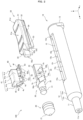
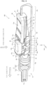
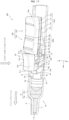
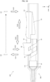
- the injection device 100 includes a syringe 10, a gasket 20, a conversion portion 30, a button 40, and a slider 50.
- Suitable materials of the syringe 10 include polypropylene (PP), cycloolefin polymer (COP), polystyrene (PS), polycarbonate (PC), and the like, which have transparency.
- PP polypropylene
- COP cycloolefin polymer
- PS polystyrene
- PC polycarbonate
- FIG. 1 the gasket 20, conversion portion 30, button 40, and slider 50 seen behind the syringe 10 are shown by broken lines, and the inner wall of the syringe 10, and the like are also shown by broken lines.
- the syringe 10 includes a cylinder tip portion 11, a body 12, and a lid portion 13.
- the body 12 is formed in a cylindrical shape, and the cylinder tip portion 11 is connected to the tip thereof. More specifically, the body 12 includes a cylindrical peripheral wall 12m, as well as includes a tip portion 12n for connecting the peripheral wall 12m and cylinder tip portion 11.
- the tip portion 12n illustrated in FIGS. 1 and the like is tapered from the peripheral wall 12m toward the cylinder tip portion 11.
- the peripheral wall 12m of the body 12 is provided with an opening 15 having a rectangular shape in a plan view.
- the body 12 can be divided into a chemical solution storage portion 12a, a mechanism incorporation portion 12b, and an auxiliary portion 12c in terms of functionality.
- the chemical solution storage portion 12a is a portion into which the gasket 20 is to be fitted and a chemical solution C is to be charged.
- the mechanism incorporation portion 12b is a portion provided with the opening 15 and incorporates an push-out mechanism for pushing out the gasket 20 in two stages.
- the push-out mechanism is a mechanism obtained by combining the conversion portion 30, button 40 and slider 50.
- the auxiliary portion 12c has a length set on the basis of the operability of the injection device 100, or the like and has the lid portion 13 mounted on the rear end portion thereof.
- the cylinder tip portion 11 is a cylindrical member having a smaller inner and outer diameters than those of the body 12.
- the cylinder tip portion 11 is a portion that has an ejection hole 11a on the tip thereof and into which an injection needle (not shown) is to be inserted.
- the lid portion 13 is a portion for reinforcing the rear end portion of the body 12.
- the lid portion 13 illustrated in FIGS. 1 and the like has a perimeter consisting of a flat portion and a curved portion, and the flat portion is disposed on the side opposite to that on which the opening 15 disposed.
- the gasket 20 is a portion disposed near the tip of the body 12 and is made of an elastic material such as rubber.
- the gasket 20 is formed in a cylindrical shape so as to closely contact the inner wall 12r of the body 12.
- the front end portion 21 of the gasket 20 is formed so as to match the shape of the inner surface of the tip of the chemical solution storage portion 12a.
- the front end portion 21 of the gasket 20 according to the first embodiment is tapered.
- the rear end portion of the gasket 20 is provided with a connection hole (not shown) for connecting with the conversion portion 30.
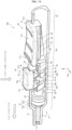
- the button 40 is disposed on the opening 15 side of the conversion portion 30 and supported by the conversion portion 30 with the sides thereof sandwiched between both side walls 15b (left and right side walls 15b) of the opening 15.
- the button 40 has a cross-sectional U-(concave)shape on a plane perpendicular to a tip direction.
- the tip direction refers to the direction in which the gasket 20 is oriented toward the tip of the body 12 and corresponds to the positive x-axis direction, that is, the forward direction in the drawings.
- the button 40 includes a face wall 41a to be pushed by a finger or the like and a pair of side walls 41b extending approximately perpendicularly to the face wall 41a from both side end portions of the face wall 41a.
- FIG. 1 shows the initial state, which is a state in which the slider 50 is in contact with the rear wall 15d of the opening 15 and the button 40 is in contact with the push end surface 51c of the slider 50.
- the button 40 is disposed such that the front end surface 41c thereof is opposed to the front wall 15c of the opening 15 and the rear end surface 41d thereof is in contact with the push end surface 51c.
- a portion including the face wall 41a and the pair of side walls 41b and having the front end surface 41c and rear end surface 41d of the button 40 is referred to as a button body 41.
- the button 40 has a pinching groove 45 formed along the tip direction from the rear end surface 41d.
- the pinching groove 45 according to the first embodiment is formed so as to range from the rear end surface 41d to the front end surface 41c of the button 40.
- the pinching groove 45 pinches the core portion 33 of the conversion portion 30.
- the button 40 includes a pair of leg portions 42 disposed so as to straddle the conversion portion 30 and each having front slopes 4s inclined with respect to the tip direction by a set angle ⁇ .
- the bottom portion 52b is a front-side portion of the bottom (lower surface) of the pinching portion 52 exposed from the auxiliary portion 53.
- the button 40 is disposed such that flat surfaces 4f of upper portions of the come-out prevention portions 43 are opposed to the bottom portion 52b of the pinching portion 52. Thus, the come-out prevention portions 43 are caught on the bottom portion 52b and prevent the button 40 from falling down.
- the conversion portion 30 is connected to the rear end portion of the gasket 20 and contained in the body 12.
- the conversion portion 30 includes a fitting portion 31 to be fitted into the connection hole of the gasket 20, a neck portion 32 connected to the fitting portion 31, the plate-shaped core portion 33 connected to the neck portion 32, and a pair of engaging portions 34 disposed on both side surfaces of the core portion 33.
- the pair of engaging portions 34 are formed so as to correspond to the pair of leg portions 42 and have rear slopes 3s that slidingly contact the front slopes 4s. That is, the inclination of the rear slopes 3s is equal to the inclination of the front slopes 4s.
- the conversion portion 30 is configured to move in the tip direction in accordance with an operation of pushing down the button 40 toward the inside of the body 12.
- the slider 50 is disposed behind the conversion portion 30 and button 40.
- the slider 50 is a portion for moving the conversion portion 30 and button unit 40 in the tip direction.
- the slider 50 includes an operation portion 51, the pinching portion 52, the auxiliary portion 53, and a safety protrusion 55.
- the operation portion 51 is disposed outside the body 12, and the width Ws thereof is wider than the width (W 2 ) of the opening 15.
- the pinching portion 52 is connected to the surface opposite to the operation surface 51a of the operation portion 51 and is disposed so as to be sandwiched between the side walls 15b of the opening 15.
- the width of the pinching portion 52 is equal to or slightly smaller than the width (W 2 ) of the opening 15.
- the safety protrusion 55 is disposed on the button 40 side of the operation portion 51 and is formed so as to be insertable into the pinching groove 45 of the button 40.
- the tip end surface 55c of the safety protrusion 55 is flush with the rear end surface 41d.
- the stretched state is a state in which the button 40 is disposed in the frontmost position in the opening 15 and the slider 50 is disposed in the rearmost position in the opening 15.
- the frontmost position of the button unit 40 in the opening 15 is the position in which the button 40 contacts the front wall 15c
- the rearmost position of the slider 50 in the opening 15 is the position in which the slider 50 contacts the rear wall 15d.
- the safety protrusion 55 illustrated in the drawings is disposed so as to range from the operation portion 51 to the pinching portion 52. That is, the height in the up-down direction of the safety protrusion 55 is the sum of the height of a portion thereof connected to the operation portion 51 and the height of a portion thereof connected to the pinching portion 52. Thus, until the push-down of the button 40 is complete, the safety protrusion 55 is able to ensure a predetermined contact range between the safety protrusion 55 and the button 40 and to guide the button 40 downward in a stable state. Note that the safety protrusion 55 may be connected only to the operation portion 51.
- the push-out mechanism is assembled to the syringe 10, for example, in the following order.
- the chemical solution C is charged into the chemical solution storage portion 12a, for example, by inserting a thin pipe such as a cannula into the tip of the cylinder tip portion 11.
- a thin pipe such as a cannula
- the conversion portion 30, button 40, and slider 50 are integrally made of a resin or the like.
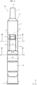
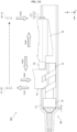
- the length of the chemical solution storage portion 12a is represented by S 1
- the length of the mechanism incorporation portion 12b that is, the length of the opening 15 is represented by T 0
- the length of the auxiliary portion 12c is represented by S 2 .
- the length S 1 is set on the basis of the size of the gasket 20, the preset dose of the chemical solution C, or the like.
- the front wall 15c may be formed such that the position thereof in the tip direction is substantially variable. That is, the syringe 10 may be configured such that the ratio between the length S 1 and the length T 0 can be adjusted.
- the dose of the chemical solution C can be adjusted, for example, by matching the amount of movement L corresponding to a stroke H with that when the length S 1 is maximized.
- the length S 2 is set in terms of the strength of the syringe 10, the ease of holding, or the like.
- the length T 0 is set such that the tip end surface 55c of the safety protrusion 55 becomes flush with the rear end surface 41d of the button 40 in the stretched state.
- the length T 1 of a region R 1 from the front wall 15c to the step 15s is set on the basis of the length Tk of the button 40.
- the length T 1 is set so as to be equal to or slightly longer than the length Tk.
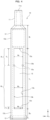
- the width W 1 of the region R 1 is set such that the resistance during operation is minimized, in consideration of the smoothness, stability, and the like of the push-down operation of the button 40.
- the width of a region R 2 from the step 15s to the rear wall 15d is narrower than the width W 1 as a whole.
- the width W 3 of a portion inside the rear wall 15d corresponding to a length T 3 is narrower than the width W 2 of the other portion.
- Narrowing the width near the rear wall 15d in this manner is intended to fix the slider 50 in contact with the rear wall 15d.
- the length T 3 is set so as to correspond to the rear end portion of the slider 50 and is much shorter than the length T 0 , as shown in FIG. 4 . It is preferable to properly adjust the width W 2 to the extent that the slidability of the button 40 and slider 50 is not impaired.
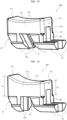
- the pair of leg portions 42 each include base portions 4a extending from one of the side walls 41b.
- the base portions 4a are disposed so as to be opposed to the side wall 15b of the opening 15.
- the base portions 4a according to the first embodiment have inwardly recessed depressions 4k in tip direction-side positions thereof adjacent to the side wall 15b of the opening 15.
- the first leg portions 42a and second leg portions 42b have the depressions 4k.
- the base portions 4a sandwiched between the side walls 15b of the opening 15 are more likely to move in the tip direction and less likely to move rearward.
- the button 40 contacts the button 40 with the front wall 15c and then moves the slider 50 rearward, movement of the button 40 in conjunction with the movement of the slider 50 is suppressed.
- the steps 15s in the opening 15 and forming the depressions 4k in the pair of leg portions 42 rearward movement of the button 40 is more accurately prevented.
- the first leg portions 42a and second leg portions 42b each include the base portion 4a extending from the side wall 41b and a fitting portion 4b extending from the base portion 4a.
- the fitting portion 4b includes a protruding portion 4m formed along the tip direction so as to contact the inner wall 12r of the body 12. As shown in FIG. 6 , the protruding portions 4m are disposed on the pair of leg portions 42 and prevent the button 40 from falling down and assist the button 40 in stably sliding.
- the come-out prevention portions 43 illustrated in FIG. 5 include plate-shaped flat portions 4h and fitting portions 4j having a shape similar to that of the fitting portions 4b. That is, the protruding portions 4m are disposed so as to extend from the second leg portions 42b to the come-out prevention portions 43, and the opposed surfaces 4r are formed in a curved shape along the inner wall 12r so as to extend from the second leg portions 42b to the come-out prevention portions 43.
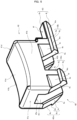
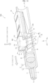
- FIG. 7 the positional relationship between the slider 50 and body 12 will be described.
- the boundaries between the members are shown by broken lines for convenience.
- left and right corners E located on the boundary between the operation portion 51 and pinching portion 52 extend linearly along the front-rear direction and are supported by the upper end of the opening 15.
- the width of the slider 50 in the positions of the pair of protruding portions 54 is wider than the width (W 2 ) of the opening 15, and the contact ends F of the protruding portions 54 can contact the inner wall 12r.
- the contact ends F of the pair of protruding portions 54 extend linearly along the front-rear direction.
- the slider 50 is shaped such that the pinching portion 52 between the operation portion 51 and protruding portions 54 is relatively recessed in a cross-sectional view.
- the positions of the side walls 15b of the opening 15 of the syringe 10 are constrained by the corners E and contact ends F of the slider 50 (two-line constraint).
- the opening 15 serves as a rail for causing the slider 50 to stably slide.
- FIGS. 8 to 11 a series of operations related to injection using the injection device 100 will be described.
- FIGS. 8 to 11 illustrate the syringe 10 whose half is cut off.
- the portion into which the chemical solution C is charged is dotted so that the movement of the chemical solution C is clarified.
- FIG. 8 shows the injection device 100 put in the initial state.
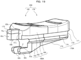
- FIG. 9 shows the injection device 100 put in a push-out state, which is a state in which the slider 50 is in contact with the button 40 disposed in the frontmost position in the opening 15. In FIG. 9 , the button 40 is in contact with both the front wall 15c of the opening 15 and the push end surface 51c of the slider 50.
- FIG. 10 shows the injection device 100 put in the stretched state.
- FIG. 11 shows the injection device 100 put in an injection completion state, which is a state in which the button 40 is pushed down in the stretched state of FIG. 10 .
- the conversion portion 30 and button 40 also slide in the tip direction. Then, as seen in the push-out state of FIG. 9 , the push-out mechanism stops moving with the button 40 contacting the front wall 15c of the opening 15.
- the gasket 20 moves in the tip direction along with the conversion portion 30 by the length Te (see FIG. 3 ). That is, the user is able to remove air by operating the slider 50 so that the injection device 100 makes the transition from the initial state to the push-out state.
- the transition from the initial state to the push-out state is also referred to as "air removal.”
- the preset prescribed amount of chemical solution C remains in the chemical solution storage portion 12a.
- the slider 50 When the slider 50 is slid rearward in the injection device 100 put in the push-out state, the slider 50 alone moves rearward. When the slider 50 contacts the rear wall 15d of the opening 15, it stops moving, as seen in the stretched state of FIG. 10 . At this time, the safety protrusion 55 is gradually removed from the pinching groove 45.
- the tip end surface 55c of the safety protrusion 55 is flush with the rear end surface 41d of the button 40.
- the user is able to push down the button 40 along the tip end surface 55c of the safety protrusion 55.
- the position of the button 40 is maintained mainly by the static friction between the front slopes 4s and the rear slopes 3s of the conversion portion 30 and the static friction between the gasket 20 connected to the conversion portion 30 and the syringe 10.
- the button 40 When the button 40 is pushed down in the injection device 100 in the stretched state, the movement in the push-down direction of the button 40 is converted into movement in the tip direction by the conversion portion 30 and the gasket 20 moves toward the front end of the body 12.
- the button 40 When the button 40 is pushed down to the maximum extent possible (by the stroke H) in the injection device 100 according to the first embodiment, the gasket 20 contacts the tip portion of the body 12 and the prescribed amount of chemical solution C is injected from the injection needle mounted on the cylinder tip portion 11 into the injection subject or the like, as shown in FIG. 11 .
- the amount of movement L is the distance of movement in the tip direction of the gasket 20 when the button 40 is pushed down to the maximum extent possible. While the cross-sectional shape of the protruding portions 4m is approximately a circular shape herein, it is not limited to such a shape.
- the set angle ⁇ is set in the range of, for example, 45° to 65°.
- the set angle ⁇ may be arbitrarily adjusted to an angle inside or outside the above range in accordance with the size of the entire injection device, the dose of the chemical solution C, or the like. The same also applies to second and third embodiments.
- the injection device 100 includes the conversion portion 30 contained in the body 12, the button 40 supported by the conversion portion 30 with the side portions thereof sandwiched between the side walls 15b of the opening 15, and the slider 50 for moving the conversion portion 30 and button 40 in the tip direction.
- the button 40 includes the pair of leg portions 42 having the front slopes 4s
- the conversion portion 30 includes the pair of engaging portions 34 having the rear slopes 3s that slidingly contact the front slopes 4s of the button 40.
- the user is also able to inject the liquid to the injection subject by operating the button 40 located on a side portion of the body 12 so that the conversion portion 30 is further moved in the tip direction. This eliminates frequent switching of the injection device area to be held from the series of operations related to injection and reduces the load on the injection subject.
- a predetermined force is required to push down a plunger. This and the needle position and the operation area being away from each other are more likely to cause an injection device shake.
- An injection device shake during injection may cause a shift in the position of the needle after the needle is punctured and may damage the punctured portion or its vicinity.
- the user only has to perform a simple operation of pushing down the button 40 and thus is able to move the conversion portion 30 connected to the gasket 20 in the tip direction and to inject the chemical solution C into the body of a human or animal, or the like.
- the user is able to push the button 40 using only the index finger.
- the user is able to support the injection device 100 using the remaining fingers and thus to operate the injection device 100 stably.
- the button 40 has the pinching groove 45 formed along the tip direction from the rear end surface 41d.
- the slider 50 includes the safety protrusion 50 disposed on the button 40 side of the operation portion 51 and formed so as to be insertable into the pinching groove 45 of the button 40.
- the safety protrusion 55 is inserted in the pinching groove 45, the user is prevented from pushing down the button 40.
- misoperation such as push-down of the button 40 and thus ejection of the chemical solution C is prevented.
- the pinching groove 45 is formed from the rear end surface 41d of the button 40 to the front end surface 41c.
- the bottom 45u of the pinching groove 45 is opposed to the core portion 33, that is, the core portion 33 becomes insertable into the pinching groove 45.
- the core portion 33 is inserted into the pinching groove 45.
- the pinching groove 45 prevents misoperation of the button 40, as well as provides the stroke H, which is the distance by which the button 40 can be pushed down, between the pinching groove 45 and the core portion 33.
- the safety protrusion 55 is formed such that the tip end surface 55c becomes flush with the rear end surface 41d in a state in which the button 40 is in contact with the front wall 15c of the opening 15 and the slider 50 is in contact with the rear wall 15d of the opening 15.
- the button 40 moves in the push-down direction with the rear end surface 41d contacting the tip end surface 55c of the safety protrusion 55.
- the slider 50 is prevented from moving rearward by the rear wall 15d of the opening 15.
- the button 40 is pushed down while being prevented from moving rearward by the safety protrusion 55.
- the operation in the push-down direction of the button 40 is converted into operation in the tip direction of the conversion portion 30 as it is, and the user is able to surely inject the prescribed amount of chemical solution C charged into the chemical solution storage portion 12a into the human body or the like.
- the slider 50 may include the operation portion 51 formed such that the width Ws becomes wider than the width (W 2 ) of the opening 15, the pinching portion 52 connected to the operation portion 51 and disposed between the side walls 15b of the opening 15, and the auxiliary portion 53 connected to the pinching portion 52 and disposed inside the body 12.
- the auxiliary portion 53 may include the pair of protruding portions 54 formed along the tip direction so as to contact the inner wall 12r of the body 12.
- the side walls 15b of the opening 15 are sandwiched between both side end portions of the operation portion 51 and the pair of protruding portions 54 while being opposed to the pinching portion 52.
- the opening 15 serves as a rail for causing the slider 50 to smoothly slide in the front-rear direction.
- the slider 50 is prevented from falling down from the syringe 10 by the pair of protruding portions 54.
- the auxiliary portion 53 may be formed such that a step is formed between the auxiliary portion 53 and the pinching portion 52 on the button 40 side.
- the pair of leg portions 42 may include the first leg portions 42a disposed on the gasket 20 side and the second leg portions 42b disposed on the slider 50 side.
- the button 40 may include the pair of come-out prevention portions 43 that extend rearward from lower portions of the second leg portions 42b and are to be engaged with the bottom portion 52b of the pinching portion 52. Fall-down of the slider 50 is suppressed by the pair of protruding portions 54, and the button 40 put in the initial state and the push-out state is disposed such that the come-out prevention portions 43 are opposed to the bottom portion 52b of the pinching portion 52. Thus, fall-down of the button 40 is more surely prevented.
- the opening 15 becomes wider in the tip direction from the position of the rear end surface 41d of the button 40 in contact with the front wall 15c. That is, the steps 15s are formed in positions of the rear end surface 41d of the button 40 in contact with the front wall 15c on the side walls 15b of the opening 15.
- the button 40 moves in the tip direction in accordance with an operation on the slider 50, it moves from a narrower portion (width W 2 ) to a wider portion (width W 1 ) of the opening 15.
- the button 40 that has entered the region having the width W 2 is prevented from moving rearward by the steps 15s, which are narrower rearward.
- the user contacts the button 40 with the front wall 15c and then moves the slider 50 rearward, the user is able to avoid a situation in which the button 40 moves rearward in conjunction with the movement of the slider 50.
- the pair of leg portions 42 each include the base portions 4a extending from the side walls 41b.
- the base portions 4a may have the depressions 4k in the tip direction-side positions thereof adjacent to the side walls 15b of the opening 15. Since the front-side resistance of the base portions 4a is reduced by the depressions 4k, the button 40 smoothly moves in the tip direction . Also, the rear-side resistance of the base portions 4a is relatively increased due to the presence of the depressions 4k. This suppresses rearward movement of the button 40.
- the pair of leg portions 42 may each include the base portions 4a extending from the side walls 41b and the fitting portions 4b extending from the base portions 4a.
- the fitting portions 4b have a curved shape in which the opposed surfaces 4r disposed so as to be opposed to the inner wall 12r of the body are along the inner wall 12r of the body 12. This shape provides a longer core 33-side length to the fitting portions 4b.
- the fitting portions 4b are tapered inwardly and have a predetermined length in the up-down direction on the core portion 33 side, as shown in FIG. 6 .
- the shape of the opposed surfaces 4r is along the inner wall 12r.
- the maximum stroke H is ensured while maintaining placement stability.
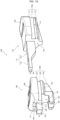
- the pair of leg portions 42 of a button 40A have front slopes 4s inclined with respect to the tip direction by a set angle ⁇ and rear auxiliary slopes 4t inclined with respect to the tip direction by the set angle ⁇ .
- the leg portions 42 have a parallelogram shape in a side view.
- the front slopes 4s are disposed on the front side of the leg portions 42, and the rear auxiliary slopes 4t are disposed on the rear side of the leg portions 42.
- the pair of engaging portions 34 of a conversion portion 30A each include a first engaging portion 34a and a second engaging portion 34b.
- the first engaging portion 34a has a rear slope 3s that slidingly contacts the front slope 4s of one leg portion 42.
- the second engaging portion 34b according to the modification A has a front auxiliary slope 3t that slidingly contacts the rear auxiliary slopes 4t of the leg portion 42.
- the other configurations of the conversion portion 30A and button 40A are similar to those of the conversion portion 30 and button 40 described above.
- the syringe 10, gasket 20, and slider 50 of the injection device 100A are similar to those of the injection device 100.
- the configurations and alternative configurations of the injection device 100 can be applied to the injection device 100A.
- the button 40A is stably supported even if each leg portion 42 is not divided into two portions, that is, a front portion and a rear portion. That is, in the injection device 100A, the leg portions 42 of the button 40A slide in groovy portions between the first engaging portions 34a and second engaging portions 34b. That is, the first engaging portions 34a and second engaging portions 34b serve as rails for guiding the leg portions 42 when the user pushes down the button 40A. Thus, the user is able to smoothly and stably operate the button 40A. Other advantageous effects and the like are similar to those of the injection device 100.
- the configuration of the button 40B of an injection device 100 according to a modification B of the first embodiment will be described.
- the syringe 10, gasket 20, conversion portion 30, and slider 50 of the injection device 100 according to the modification B are similar to those of the above injection device 100.
- the conversion portion 30 is required to have front auxiliary slopes 3t inclined with respect to the tip direction by a set angle ⁇ , as shown in an example in FIG. 2 .
- Components similar to the above button 40 and button 40A are given the same reference signs, and the description thereof will be omitted or simplified.
- the first leg portions 42a of a pair of leg portions 42 have front slopes 4s that slidingly contact the rear slopes 3s of the conversion portion 30 and rear auxiliary slopes 4t that slidingly contact the front auxiliary slopes 3t (see FIG. 2 ) of the conversion portion 30. That is, the first leg portions 42a have a parallelogram shape in a side view. Thus, both sides of the first leg portions 42a of the button 40B are sandwiched between the first engaging portions 34a and second engaging portions 34b of the conversion portion 30. Thus, the button 40B is stably supported by the conversion portion 30. Thus, the operation stability of the button 40B is increased.
- Other advantageous effects and the like are similar to those of the injection device 100 according to the first embodiment and the injection device 100A according to the modification A.
- buttons 40, 40A, and 40B are similar to those of the above injection devices 100.
- Components similar to the buttons 40, 40A, and 40B are given the same reference signs, and the description thereof will be omitted or simplified.
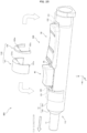
- the second slider 170 includes a second body 170A disposed outside the body 12 and including a second operation portion 171 formed so as to have a wider width than the width (W 2 ) of the opening 15.
- the second body 170A includes a second sandwiched portion 172 disposed between the side walls 15b of the opening 15 and a second auxiliary portion 173 disposed inside the body 12.
- the second auxiliary portion 173 includes a pair of protruding portions 174 formed along the tip direction so as to contact the inner wall 12r of the body 12.
- the shape of the protruding portions 174 is similar to that of the protruding portions 54 according to the first embodiment.
Landscapes
- Health & Medical Sciences (AREA)
- Vascular Medicine (AREA)
- Engineering & Computer Science (AREA)
- Anesthesiology (AREA)
- Biomedical Technology (AREA)
- Heart & Thoracic Surgery (AREA)
- Hematology (AREA)
- Life Sciences & Earth Sciences (AREA)
- Animal Behavior & Ethology (AREA)
- General Health & Medical Sciences (AREA)
- Public Health (AREA)
- Veterinary Medicine (AREA)
- Infusion, Injection, And Reservoir Apparatuses (AREA)
Claims (4)
- Injektionsvorrichtung (100, 100A; 400, 500) zur manuellen Betätigung durch einen Benutzer, wobei die Injektionsvorrichtung umfasst:eine Spritze (10, 110), welche einen röhrenförmigen Körper (12) umfasst, wobei der Körper (12) in einer Umfangswand (12m) eine Öffnung (15) aufweist, welche in einer Draufsicht eine rechteckige Form aufweist;einen Umwandlungsabschnitt (30, 30A), welcher mit einem hinteren Endabschnitt einer Dichtung (20) verbunden ist, welche an einer Spitzenseite des Körpers (12) angeordnet ist, wobei der Umwandlungsabschnitt (30, 30A) in dem Körper (12) enthalten ist;einen Druckknopf (40, 40A, 40B, 40C), welcher an einer Seite des Umwandlungsabschnitts (30, 30A) in der Nähe der Öffnung (15) angeordnet ist und durch den Umwandlungsabschnitt (30, 30A) gehaltert ist, wobei Seitenabschnitte des Druckknopfs (40, 40A, 40B, 40C) zwischen beiden Seitenwänden (15b) der Öffnung (15) eingefügt sind, wobei die Injektionsvorrichtung gekennzeichnet ist, durcheinen Schieber (50, 350), welcher in der Öffnung (15) in der Umfangswand (12m) des Körpers (12) angeordnet ist und dazu eingerichtet ist, den Umwandlungsabschnitt (30, 30A) und den Druckknopf (40, 40A, 40B, 40C) in einer Spitzenrichtung zu bewegen, welche eine Richtung ist, in welcher sich die Dichtung (20) in Richtung einer Spitze des Körpers (12) bewegt,wobei der Druckknopf (40, 40A, 40B, 40C) an einer Ebene, welche zu der Spitzenrichtung senkrecht ist, im Querschnitt eine U-Form aufweist und ein Paar von Beinabschnitten (42) umfasst, welche derart angeordnet sind, dass sie den Umwandlungsabschnitt (30, 30A) überspannen, und welche vordere Flanken (4s) aufweisen, welche in Bezug auf die Spitzenrichtung um einen festgelegten Winkel (θ) geneigt sind, undwobei der Umwandlungsabschnitt (30, 30A) ein Paar von Eingriffsabschnitten (34) umfasst, welche gebildet sind, um dem Paar von Beinabschnitten (42) zu entsprechen, und welche hintere Flanken (3s) aufweisen, welche die vorderen Flanken (4s) schiebend kontaktieren, und welche dazu eingerichtet sind, sich in der Spitzenrichtung in Übereinstimmung mit der Betätigung eines Herunterdrückens des Druckknopfs (40, 40A, 40B, 40C) in Richtung des Inneren des Körpers (12) zu bewegen.
- Injektionsvorrichtung (100, 100A; 400, 500) nach Anspruch 1,wobei der Druckknopf (40, 40A, 40B, 40C) eine Klemmnut (45) aufweist, welche entlang der Spitzenrichtung von einer hinteren Endfläche (41d) des Druckknopfs (40, 40A, 40B, 40C) gebildet ist; undwobei der Schieber (50, 350) umfasst:einen Betätigungsabschnitt (51), welcher außerhalb des Körpers (12) angeordnet ist und eine breitere Breite als eine Breite der Öffnung (15) aufweist; undeinen Sicherheitsvorsprung (55, 175), welcher an einer Seite des Betätigungsabschnitts (51) in der Nähe des Druckknopfs (40, 40A, 40B, 40C) angeordnet ist und derart gebildet ist, dass er in die Klemmnut (45) einführbar ist.
- Injektionsvorrichtung (400, 500) nach Anspruch 1,
wobei der Schieber (350) umfasst:einen ersten Schieber (160), welcher an einer Seite in der Nähe des Druckknopfs (40, 40A, 40B, 40C) angeordnet ist; undeinen zweiten Schieber (170), welcher an einer Seite in der Nähe einer hinteren Wand (15d) der Öffnung (15) angeordnet ist,wobei der Druckknopf (40, 40A, 40B, 40C) eine Klemmnut (45) aufweist, welche entlang der Spitzenrichtung von einer hinteren Endfläche (41d) des Druckknopfs (40, 40A, 40B, 40C) gebildet ist,wobei der erste Schieber (160) umfasst:einen ersten Körper (160A), welcher ein Kommunikationsloch (65h) aufweist, welches sich von einer Stoß-Endfläche (51c), welche eine vordere Endfläche darstellt, zu einer hinteren Endfläche (60d) erstreckt; undeinen Begrenzungsvorsprung (165), welcher sich in der Spitzenrichtung von dem ersten Körper(160A) erstreckt und derart gebildet ist, dass er in die Klemmnut (45) einführbar ist,wobei der zweite Schieber (170) umfasst:einen Betätigungsabschnitt (171), welcher außerhalb des Körpers (12) angeordnet ist und derart gebildet ist, dass er eine breitere Breite als eine Breite der Öffnung (15) aufweist; undeinen Sicherheitsvorsprung (175), welcher an einer Seite des Betätigungsabschnitts (171) in der Nähe des Druckknopfs (40, 40A, 40B, 40C) angeordnet ist und derart gebildet ist, dass er in das Kommunikationsloch (65h) und die Klemmnut (45) einführbar ist, undwobei ein Spitzenabschnitt (75n) des Sicherheitsvorsprungs (175) an dem Begrenzungsvorsprung (165) angeordnet ist, wobei der zweite Schieber (170) die hintere Endfläche (60d) des ersten Schiebers (160) kontaktiert. - Injektionseinheit (800), umfassend:die Injektionsvorrichtung (100, 100A; 400, 500) nach einem der Ansprüche 1 bis 3; undein oder mehrere Anpassungselemente (121, 122), welches/welche dazu eingerichtet ist/sind, die vorderste Position des Druckknopfs (40, 40A, 40B, 40C) in der Öffnung (15) anzupassen, wobeidas eine oder die mehreren Anpassungselemente (121, 122) einen Abstandshalter umfasst/umfassen, welcher eine voreingestellte Breite aufweist und zwischen den Seitenwänden (15b) der Öffnung (15) angeordnet ist.
Applications Claiming Priority (3)
| Application Number | Priority Date | Filing Date | Title |
|---|---|---|---|
| JP2022136543 | 2022-08-30 | ||
| JP2022155625A JP7202587B1 (ja) | 2022-08-30 | 2022-09-28 | 注射器及び注射器ユニット |
| PCT/JP2023/017870 WO2024047956A1 (ja) | 2022-08-30 | 2023-05-12 | 注射器及び注射器ユニット |
Publications (4)
| Publication Number | Publication Date |
|---|---|
| EP4353280A1 EP4353280A1 (de) | 2024-04-17 |
| EP4353280A4 EP4353280A4 (de) | 2024-07-10 |
| EP4353280B1 true EP4353280B1 (de) | 2025-03-26 |
| EP4353280C0 EP4353280C0 (de) | 2025-03-26 |
Family
ID=84887153
Family Applications (1)
| Application Number | Title | Priority Date | Filing Date |
|---|---|---|---|
| EP23782722.5A Active EP4353280B1 (de) | 2022-08-30 | 2023-05-12 | Spritze und spritzeneinheit |
Country Status (4)
| Country | Link |
|---|---|
| US (1) | US12370323B2 (de) |
| EP (1) | EP4353280B1 (de) |
| JP (1) | JP7202587B1 (de) |
| WO (1) | WO2024047956A1 (de) |
Family Cites Families (13)
| Publication number | Priority date | Publication date | Assignee | Title |
|---|---|---|---|---|
| DE3509865A1 (de) * | 1985-03-19 | 1986-09-25 | Gerhard L. Dr.med. 7512 Rheinstetten Rummel | Dosiervorrichtung fuer insulinspritzen |
| CN1602212B (zh) * | 2001-12-13 | 2010-04-07 | 松下电器产业株式会社 | 医疗用投药器具 |
| US20050187303A1 (en) * | 2002-09-26 | 2005-08-25 | Wu Men-Dar | Therapeutic causing contraction of mucosal tissue, method of treating diseases relating to mucosal tissues, injector and therapeutic set |
| WO2004028518A1 (ja) * | 2002-09-26 | 2004-04-08 | Japan Science And Technology Agency | 粘膜組織収縮性治療剤、粘膜組織に関わる疾患の治療方法、注射器、及び治療具セット |
| AU2004231966A1 (en) * | 2003-04-16 | 2004-11-04 | Allergan, Inc. | Controlled volume injection/aspiration device |
| TWM360049U (en) | 2009-01-22 | 2009-07-01 | zhuo-ying Chen | Disposable safety syringe structure improvement |
| JP5749084B2 (ja) | 2011-05-31 | 2015-07-15 | 株式会社吉野工業所 | 使い切り注射器 |
| CN112312868B (zh) * | 2018-04-12 | 2023-12-22 | 新世界医学有限公司 | 用于眼内流体注射的装置和方法 |
| US11364346B2 (en) * | 2018-06-19 | 2022-06-21 | Innomed Technologies, Inc. | Precision low-dose, low-waste syringes and ergonomic attachments therefor |
| PH12021552617A1 (en) * | 2019-04-18 | 2022-07-11 | Boehringer Ingelheim Int | Administration device for administration of a fluid |
| US11707601B2 (en) * | 2020-02-24 | 2023-07-25 | Becton, Dickinson And Company | Cover to facilitate reduced-touch insertion of a catheter and related systems and methods |
| CN113559361A (zh) * | 2021-08-27 | 2021-10-29 | 天津科技大学 | 一种能缓慢推药的胰岛素注射器 |
| US12576246B2 (en) * | 2022-06-07 | 2026-03-17 | Becton, Dickinson And Company | Catheter system having a guidewire slider |
-
2022
- 2022-09-28 JP JP2022155625A patent/JP7202587B1/ja active Active
-
2023
- 2023-05-12 EP EP23782722.5A patent/EP4353280B1/de active Active
- 2023-05-12 WO PCT/JP2023/017870 patent/WO2024047956A1/ja not_active Ceased
- 2023-05-12 US US18/554,715 patent/US12370323B2/en active Active
Also Published As
| Publication number | Publication date |
|---|---|
| JP2024035001A (ja) | 2024-03-13 |
| WO2024047956A1 (ja) | 2024-03-07 |
| EP4353280A1 (de) | 2024-04-17 |
| JP7202587B1 (ja) | 2023-01-12 |
| US12370323B2 (en) | 2025-07-29 |
| EP4353280C0 (de) | 2025-03-26 |
| US20240269391A1 (en) | 2024-08-15 |
| EP4353280A4 (de) | 2024-07-10 |
Similar Documents
| Publication | Publication Date | Title |
|---|---|---|
| US11957870B2 (en) | Drug delivery device | |
| JP6334120B2 (ja) | 薬物注入のための角度付き挿入器 | |
| US7364570B2 (en) | Controlled volume injection/aspiration device | |
| JP4740847B2 (ja) | 注入装置 | |
| KR102423716B1 (ko) | 트랙 색인된 주사기 | |
| EP4134116B1 (de) | Sicherheitsfunktion für eine arzneimittelabgabevorrichtung | |
| KR102231985B1 (ko) | 손바닥 작동식 약물 전달 장치 | |
| EP3760256B1 (de) | Fettabsaug- und transplantatspritze mit mitteln zur einstellung des unterdrucks | |
| JP6473132B2 (ja) | 自動傾斜式注入セット組立体 | |
| KR100826227B1 (ko) | 약액 카트리지용 보유 기구를 가진 펜형 주사기 | |
| KR101066819B1 (ko) | 환자 제어식 약물 투여 장치 | |
| JP2018508296A (ja) | 収束ランプを有する駆動機構を備える分注装置 | |
| JP2025528423A (ja) | 注入セット、インサータアセンブリ、システム、および方法 | |
| EP4353280B1 (de) | Spritze und spritzeneinheit | |
| US20040039302A1 (en) | Disposable lancing device | |
| CN115814218B (zh) | 一种设有防分离结构的粉雾剂吸入器械 | |
| KR101628349B1 (ko) | 시린지 교체형 자동투약기 | |
| KR20170052782A (ko) | 약물 자동 주입장치 | |
| JP7324555B1 (ja) | 注射器及び一体押子の製造方法 | |
| US20210260303A1 (en) | Medication delivery device and medication delivery assembly | |
| EP4255533B1 (de) | Injektionsvorrichtung für medizinische zwecke | |
| JPH0857049A (ja) | 使い捨て輸液セット | |
| JPH06451U (ja) | インスリン投与用注射器 |
Legal Events
| Date | Code | Title | Description |
|---|---|---|---|
| STAA | Information on the status of an ep patent application or granted ep patent |
Free format text: STATUS: UNKNOWN |
|
| STAA | Information on the status of an ep patent application or granted ep patent |
Free format text: STATUS: THE INTERNATIONAL PUBLICATION HAS BEEN MADE |
|
| PUAI | Public reference made under article 153(3) epc to a published international application that has entered the european phase |
Free format text: ORIGINAL CODE: 0009012 |
|
| STAA | Information on the status of an ep patent application or granted ep patent |
Free format text: STATUS: REQUEST FOR EXAMINATION WAS MADE |
|
| 17P | Request for examination filed |
Effective date: 20231011 |
|
| AK | Designated contracting states |
Kind code of ref document: A1 Designated state(s): AL AT BE BG CH CY CZ DE DK EE ES FI FR GB GR HR HU IE IS IT LI LT LU LV MC ME MK MT NL NO PL PT RO RS SE SI SK SM TR |
|
| A4 | Supplementary search report drawn up and despatched |
Effective date: 20240611 |
|
| RIC1 | Information provided on ipc code assigned before grant |
Ipc: A61M 5/315 20060101ALI20240605BHEP Ipc: A61M 5/31 20060101ALI20240605BHEP Ipc: A61M 5/178 20060101AFI20240605BHEP |
|
| GRAP | Despatch of communication of intention to grant a patent |
Free format text: ORIGINAL CODE: EPIDOSNIGR1 |
|
| STAA | Information on the status of an ep patent application or granted ep patent |
Free format text: STATUS: GRANT OF PATENT IS INTENDED |
|
| DAV | Request for validation of the european patent (deleted) | ||
| DAX | Request for extension of the european patent (deleted) | ||
| INTG | Intention to grant announced |
Effective date: 20241104 |
|
| GRAS | Grant fee paid |
Free format text: ORIGINAL CODE: EPIDOSNIGR3 |
|
| GRAA | (expected) grant |
Free format text: ORIGINAL CODE: 0009210 |
|
| STAA | Information on the status of an ep patent application or granted ep patent |
Free format text: STATUS: THE PATENT HAS BEEN GRANTED |
|
| AK | Designated contracting states |
Kind code of ref document: B1 Designated state(s): AL AT BE BG CH CY CZ DE DK EE ES FI FR GB GR HR HU IE IS IT LI LT LU LV MC ME MK MT NL NO PL PT RO RS SE SI SK SM TR |
|
| REG | Reference to a national code |
Ref country code: GB Ref legal event code: FG4D |
|
| REG | Reference to a national code |
Ref country code: CH Ref legal event code: EP |
|
| REG | Reference to a national code |
Ref country code: DE Ref legal event code: R096 Ref document number: 602023002627 Country of ref document: DE |
|
| REG | Reference to a national code |
Ref country code: IE Ref legal event code: FG4D |
|
| U01 | Request for unitary effect filed |
Effective date: 20250326 |
|
| U07 | Unitary effect registered |
Designated state(s): AT BE BG DE DK EE FI FR IT LT LU LV MT NL PT RO SE SI Effective date: 20250401 |
|
| U20 | Renewal fee for the european patent with unitary effect paid |
Year of fee payment: 3 Effective date: 20250415 |
|
| PG25 | Lapsed in a contracting state [announced via postgrant information from national office to epo] |
Ref country code: RS Free format text: LAPSE BECAUSE OF FAILURE TO SUBMIT A TRANSLATION OF THE DESCRIPTION OR TO PAY THE FEE WITHIN THE PRESCRIBED TIME-LIMIT Effective date: 20250626 |
|
| PG25 | Lapsed in a contracting state [announced via postgrant information from national office to epo] |
Ref country code: NO Free format text: LAPSE BECAUSE OF FAILURE TO SUBMIT A TRANSLATION OF THE DESCRIPTION OR TO PAY THE FEE WITHIN THE PRESCRIBED TIME-LIMIT Effective date: 20250626 |
|
| PG25 | Lapsed in a contracting state [announced via postgrant information from national office to epo] |
Ref country code: HR Free format text: LAPSE BECAUSE OF FAILURE TO SUBMIT A TRANSLATION OF THE DESCRIPTION OR TO PAY THE FEE WITHIN THE PRESCRIBED TIME-LIMIT Effective date: 20250326 |
|
| PG25 | Lapsed in a contracting state [announced via postgrant information from national office to epo] |
Ref country code: GR Free format text: LAPSE BECAUSE OF FAILURE TO SUBMIT A TRANSLATION OF THE DESCRIPTION OR TO PAY THE FEE WITHIN THE PRESCRIBED TIME-LIMIT Effective date: 20250627 |
|
| PG25 | Lapsed in a contracting state [announced via postgrant information from national office to epo] |
Ref country code: SM Free format text: LAPSE BECAUSE OF FAILURE TO SUBMIT A TRANSLATION OF THE DESCRIPTION OR TO PAY THE FEE WITHIN THE PRESCRIBED TIME-LIMIT Effective date: 20250326 |
|
| PG25 | Lapsed in a contracting state [announced via postgrant information from national office to epo] |
Ref country code: ES Free format text: LAPSE BECAUSE OF FAILURE TO SUBMIT A TRANSLATION OF THE DESCRIPTION OR TO PAY THE FEE WITHIN THE PRESCRIBED TIME-LIMIT Effective date: 20250326 |
|
| PG25 | Lapsed in a contracting state [announced via postgrant information from national office to epo] |
Ref country code: PL Free format text: LAPSE BECAUSE OF FAILURE TO SUBMIT A TRANSLATION OF THE DESCRIPTION OR TO PAY THE FEE WITHIN THE PRESCRIBED TIME-LIMIT Effective date: 20250326 |
|
| PG25 | Lapsed in a contracting state [announced via postgrant information from national office to epo] |
Ref country code: SK Free format text: LAPSE BECAUSE OF FAILURE TO SUBMIT A TRANSLATION OF THE DESCRIPTION OR TO PAY THE FEE WITHIN THE PRESCRIBED TIME-LIMIT Effective date: 20250326 |
|
| PG25 | Lapsed in a contracting state [announced via postgrant information from national office to epo] |
Ref country code: IS Free format text: LAPSE BECAUSE OF FAILURE TO SUBMIT A TRANSLATION OF THE DESCRIPTION OR TO PAY THE FEE WITHIN THE PRESCRIBED TIME-LIMIT Effective date: 20250726 |
|
| PG25 | Lapsed in a contracting state [announced via postgrant information from national office to epo] |
Ref country code: CZ Free format text: LAPSE BECAUSE OF FAILURE TO SUBMIT A TRANSLATION OF THE DESCRIPTION OR TO PAY THE FEE WITHIN THE PRESCRIBED TIME-LIMIT Effective date: 20250326 |
|
| PG25 | Lapsed in a contracting state [announced via postgrant information from national office to epo] |
Ref country code: MC Free format text: LAPSE BECAUSE OF FAILURE TO SUBMIT A TRANSLATION OF THE DESCRIPTION OR TO PAY THE FEE WITHIN THE PRESCRIBED TIME-LIMIT Effective date: 20250326 |
|
| PLBE | No opposition filed within time limit |
Free format text: ORIGINAL CODE: 0009261 |
|
| STAA | Information on the status of an ep patent application or granted ep patent |
Free format text: STATUS: NO OPPOSITION FILED WITHIN TIME LIMIT |
|
| REG | Reference to a national code |
Ref country code: CH Ref legal event code: L10 Free format text: ST27 STATUS EVENT CODE: U-0-0-L10-L00 (AS PROVIDED BY THE NATIONAL OFFICE) Effective date: 20260211 |
|
| 26N | No opposition filed |
Effective date: 20260105 |
|
| PG25 | Lapsed in a contracting state [announced via postgrant information from national office to epo] |
Ref country code: IE Free format text: LAPSE BECAUSE OF NON-PAYMENT OF DUE FEES Effective date: 20250512 |
|
| U20 | Renewal fee for the european patent with unitary effect paid |
Year of fee payment: 4 Effective date: 20260316 |