EP4352276B1 - Vorrichtung und verfahren zur abgabe einer gasphase eines festen vorläufers - Google Patents
Vorrichtung und verfahren zur abgabe einer gasphase eines festen vorläufers Download PDFInfo
- Publication number
- EP4352276B1 EP4352276B1 EP22723129.7A EP22723129A EP4352276B1 EP 4352276 B1 EP4352276 B1 EP 4352276B1 EP 22723129 A EP22723129 A EP 22723129A EP 4352276 B1 EP4352276 B1 EP 4352276B1
- Authority
- EP
- European Patent Office
- Prior art keywords
- container
- vessel
- temperature
- heating means
- enclosure
- Prior art date
- Legal status (The legal status is an assumption and is not a legal conclusion. Google has not performed a legal analysis and makes no representation as to the accuracy of the status listed.)
- Active
Links
Images


Classifications
-
- C—CHEMISTRY; METALLURGY
- C23—COATING METALLIC MATERIAL; COATING MATERIAL WITH METALLIC MATERIAL; CHEMICAL SURFACE TREATMENT; DIFFUSION TREATMENT OF METALLIC MATERIAL; COATING BY VACUUM EVAPORATION, BY SPUTTERING, BY ION IMPLANTATION OR BY CHEMICAL VAPOUR DEPOSITION, IN GENERAL; INHIBITING CORROSION OF METALLIC MATERIAL OR INCRUSTATION IN GENERAL
- C23C—COATING METALLIC MATERIAL; COATING MATERIAL WITH METALLIC MATERIAL; SURFACE TREATMENT OF METALLIC MATERIAL BY DIFFUSION INTO THE SURFACE, BY CHEMICAL CONVERSION OR SUBSTITUTION; COATING BY VACUUM EVAPORATION, BY SPUTTERING, BY ION IMPLANTATION OR BY CHEMICAL VAPOUR DEPOSITION, IN GENERAL
- C23C16/00—Chemical coating by decomposition of gaseous compounds, without leaving reaction products of surface material in the coating, i.e. chemical vapour deposition [CVD] processes
- C23C16/44—Chemical coating by decomposition of gaseous compounds, without leaving reaction products of surface material in the coating, i.e. chemical vapour deposition [CVD] processes characterised by the method of coating
- C23C16/448—Chemical coating by decomposition of gaseous compounds, without leaving reaction products of surface material in the coating, i.e. chemical vapour deposition [CVD] processes characterised by the method of coating characterised by the method used for generating reactive gas streams, e.g. by evaporation or sublimation of precursor materials
- C23C16/4481—Chemical coating by decomposition of gaseous compounds, without leaving reaction products of surface material in the coating, i.e. chemical vapour deposition [CVD] processes characterised by the method of coating characterised by the method used for generating reactive gas streams, e.g. by evaporation or sublimation of precursor materials by evaporation using carrier gas in contact with the source material
-
- B—PERFORMING OPERATIONS; TRANSPORTING
- B01—PHYSICAL OR CHEMICAL PROCESSES OR APPARATUS IN GENERAL
- B01D—SEPARATION
- B01D1/00—Evaporating
- B01D1/0082—Regulation; Control
-
- B—PERFORMING OPERATIONS; TRANSPORTING
- B01—PHYSICAL OR CHEMICAL PROCESSES OR APPARATUS IN GENERAL
- B01D—SEPARATION
- B01D7/00—Sublimation
-
- C—CHEMISTRY; METALLURGY
- C23—COATING METALLIC MATERIAL; COATING MATERIAL WITH METALLIC MATERIAL; CHEMICAL SURFACE TREATMENT; DIFFUSION TREATMENT OF METALLIC MATERIAL; COATING BY VACUUM EVAPORATION, BY SPUTTERING, BY ION IMPLANTATION OR BY CHEMICAL VAPOUR DEPOSITION, IN GENERAL; INHIBITING CORROSION OF METALLIC MATERIAL OR INCRUSTATION IN GENERAL
- C23C—COATING METALLIC MATERIAL; COATING MATERIAL WITH METALLIC MATERIAL; SURFACE TREATMENT OF METALLIC MATERIAL BY DIFFUSION INTO THE SURFACE, BY CHEMICAL CONVERSION OR SUBSTITUTION; COATING BY VACUUM EVAPORATION, BY SPUTTERING, BY ION IMPLANTATION OR BY CHEMICAL VAPOUR DEPOSITION, IN GENERAL
- C23C16/00—Chemical coating by decomposition of gaseous compounds, without leaving reaction products of surface material in the coating, i.e. chemical vapour deposition [CVD] processes
- C23C16/44—Chemical coating by decomposition of gaseous compounds, without leaving reaction products of surface material in the coating, i.e. chemical vapour deposition [CVD] processes characterised by the method of coating
- C23C16/448—Chemical coating by decomposition of gaseous compounds, without leaving reaction products of surface material in the coating, i.e. chemical vapour deposition [CVD] processes characterised by the method of coating characterised by the method used for generating reactive gas streams, e.g. by evaporation or sublimation of precursor materials
- C23C16/4485—Chemical coating by decomposition of gaseous compounds, without leaving reaction products of surface material in the coating, i.e. chemical vapour deposition [CVD] processes characterised by the method of coating characterised by the method used for generating reactive gas streams, e.g. by evaporation or sublimation of precursor materials by evaporation without using carrier gas in contact with the source material
-
- C—CHEMISTRY; METALLURGY
- C23—COATING METALLIC MATERIAL; COATING MATERIAL WITH METALLIC MATERIAL; CHEMICAL SURFACE TREATMENT; DIFFUSION TREATMENT OF METALLIC MATERIAL; COATING BY VACUUM EVAPORATION, BY SPUTTERING, BY ION IMPLANTATION OR BY CHEMICAL VAPOUR DEPOSITION, IN GENERAL; INHIBITING CORROSION OF METALLIC MATERIAL OR INCRUSTATION IN GENERAL
- C23C—COATING METALLIC MATERIAL; COATING MATERIAL WITH METALLIC MATERIAL; SURFACE TREATMENT OF METALLIC MATERIAL BY DIFFUSION INTO THE SURFACE, BY CHEMICAL CONVERSION OR SUBSTITUTION; COATING BY VACUUM EVAPORATION, BY SPUTTERING, BY ION IMPLANTATION OR BY CHEMICAL VAPOUR DEPOSITION, IN GENERAL
- C23C16/00—Chemical coating by decomposition of gaseous compounds, without leaving reaction products of surface material in the coating, i.e. chemical vapour deposition [CVD] processes
- C23C16/44—Chemical coating by decomposition of gaseous compounds, without leaving reaction products of surface material in the coating, i.e. chemical vapour deposition [CVD] processes characterised by the method of coating
- C23C16/455—Chemical coating by decomposition of gaseous compounds, without leaving reaction products of surface material in the coating, i.e. chemical vapour deposition [CVD] processes characterised by the method of coating characterised by the method used for introducing gases into reaction chamber or for modifying gas flows in reaction chamber
- C23C16/45557—Pulsed pressure or control pressure
-
- C—CHEMISTRY; METALLURGY
- C23—COATING METALLIC MATERIAL; COATING MATERIAL WITH METALLIC MATERIAL; CHEMICAL SURFACE TREATMENT; DIFFUSION TREATMENT OF METALLIC MATERIAL; COATING BY VACUUM EVAPORATION, BY SPUTTERING, BY ION IMPLANTATION OR BY CHEMICAL VAPOUR DEPOSITION, IN GENERAL; INHIBITING CORROSION OF METALLIC MATERIAL OR INCRUSTATION IN GENERAL
- C23C—COATING METALLIC MATERIAL; COATING MATERIAL WITH METALLIC MATERIAL; SURFACE TREATMENT OF METALLIC MATERIAL BY DIFFUSION INTO THE SURFACE, BY CHEMICAL CONVERSION OR SUBSTITUTION; COATING BY VACUUM EVAPORATION, BY SPUTTERING, BY ION IMPLANTATION OR BY CHEMICAL VAPOUR DEPOSITION, IN GENERAL
- C23C16/00—Chemical coating by decomposition of gaseous compounds, without leaving reaction products of surface material in the coating, i.e. chemical vapour deposition [CVD] processes
- C23C16/44—Chemical coating by decomposition of gaseous compounds, without leaving reaction products of surface material in the coating, i.e. chemical vapour deposition [CVD] processes characterised by the method of coating
- C23C16/455—Chemical coating by decomposition of gaseous compounds, without leaving reaction products of surface material in the coating, i.e. chemical vapour deposition [CVD] processes characterised by the method of coating characterised by the method used for introducing gases into reaction chamber or for modifying gas flows in reaction chamber
- C23C16/45561—Gas plumbing upstream of the reaction chamber
-
- C—CHEMISTRY; METALLURGY
- C23—COATING METALLIC MATERIAL; COATING MATERIAL WITH METALLIC MATERIAL; CHEMICAL SURFACE TREATMENT; DIFFUSION TREATMENT OF METALLIC MATERIAL; COATING BY VACUUM EVAPORATION, BY SPUTTERING, BY ION IMPLANTATION OR BY CHEMICAL VAPOUR DEPOSITION, IN GENERAL; INHIBITING CORROSION OF METALLIC MATERIAL OR INCRUSTATION IN GENERAL
- C23C—COATING METALLIC MATERIAL; COATING MATERIAL WITH METALLIC MATERIAL; SURFACE TREATMENT OF METALLIC MATERIAL BY DIFFUSION INTO THE SURFACE, BY CHEMICAL CONVERSION OR SUBSTITUTION; COATING BY VACUUM EVAPORATION, BY SPUTTERING, BY ION IMPLANTATION OR BY CHEMICAL VAPOUR DEPOSITION, IN GENERAL
- C23C16/00—Chemical coating by decomposition of gaseous compounds, without leaving reaction products of surface material in the coating, i.e. chemical vapour deposition [CVD] processes
- C23C16/44—Chemical coating by decomposition of gaseous compounds, without leaving reaction products of surface material in the coating, i.e. chemical vapour deposition [CVD] processes characterised by the method of coating
- C23C16/52—Controlling or regulating the coating process
-
- H—ELECTRICITY
- H10—SEMICONDUCTOR DEVICES; ELECTRIC SOLID-STATE DEVICES NOT OTHERWISE PROVIDED FOR
- H10P—GENERIC PROCESSES OR APPARATUS FOR THE MANUFACTURE OR TREATMENT OF DEVICES COVERED BY CLASS H10
- H10P72/00—Handling or holding of wafers, substrates or devices during manufacture or treatment thereof
- H10P72/04—Apparatus for manufacture or treatment
- H10P72/0402—Apparatus for fluid treatment
Definitions
- the present invention relates to a device for distributing a gaseous phase of a solid precursor intended to be used in a treatment installation.
- the invention also relates to a method for distributing a gaseous phase of a solid precursor using such a device as well as a treatment installation comprising said device.
- the invention can be applied to the distribution of precursors in various treatment processes such as etching or cleaning of substrates, deposition of coatings or thin layers.
- the invention finds particular application in the semiconductor industry, the precursor being able for example to be involved in the production of thin layers or the doping of substrates during the manufacture of electronic components or integrated circuits.
- the device according to the invention is intended to supply a gaseous phase of a precursor to a chemical vapor deposition installation.
- the precursor can be distributed pure or diluted in a carrier gas.
- a substrate is exposed to one or more gas-phase precursors, which react and/or decompose on the substrate surface to generate the desired deposit.
- precursors can be used as precursors in chemical vapor deposition processing facilities. These precursors can be in gaseous, liquid, or solid states. These three fundamental states are generally considered under standard conditions of pressure and temperature.
- Gaseous precursors are the easiest to transport to their point of use. They are generally stored under pressure in their container and thus flow naturally to a lower-pressure point of use.
- Dispensing precursors in liquid form imposes more constraints.
- One dispensing method involves withdrawing the liquid phase of the precursor from its container by injecting an immiscible inert gas, which pushes the liquid into a drop pipe.
- Another method relies on heating the liquid phase to vaporize it, while maintaining the pressure and temperature of the vapor phase until it reaches the point of use.
- precursors that exhibit interesting properties are only available in the solid state under standard conditions of pressure and temperature. These precursors can be present in the form of granules or powder. However, they generally have a very high sublimation temperature and a very low saturated vapor pressure at room temperature, and therefore cannot be distributed directly to the treatment plant, due to the small quantity of gas that would be supplied.
- the precursor concentration in the carrier gas can be difficult to control over time. Indeed, when the solid precursor is sublimed, the shape, morphology, contact surface with the carrier gas and the volume of the solid precursor change, thus modifying the vapor flow rate and therefore the precursor concentration in the carrier gas. Maintaining a constant precursor concentration in the carrier gas is all the more difficult since metrology allowing quantification is difficult to develop. In order to maintain a constant precursor concentration, the carrier gas must be saturated with precursor throughout the use of the container. Some containers have a specific design allowing saturation of the carrier gas to be achieved. When the container used has a design that does not allow saturation of the carrier gas with precursor to be achieved throughout the use of the container, the proportion of precursor in the carrier gas decreases as the container is used.
- the gas phase of the precursor must be maintained at a temperature greater than or equal to the sublimation temperature over the entire path from the container to the point of use.
- the presence of colder points on the fluid path downstream of the container can cause crystallization, i.e. condensation, of the gas phase at these points. This results in a variation in the flow rate of the precursor distributed as well as clogging of the components of the gas distribution circuit, such as valves, flow controllers, etc. and restrictions of passage in the pipes, which causes additional flow variations and malfunctions of the installation.
- the invention aims to overcome all or part of the drawbacks mentioned above, in particular by proposing a device for dispensing a gaseous phase of a solid precursor allowing stable and flexible dispensing, depending in particular on the flow rates required at the point of use of the precursor and/or the nature of the precursor, independently of the design of the container containing the precursor, and with which the risk of condensation of the gaseous phase during its transport to the point of use is greatly reduced, or even eliminated, without however making the device excessively complex.
- the device further comprising an enclosure having an internal volume in which the container, the first heating means and the dispensing means are arranged, the enclosure having a substantially vertical axial direction and oriented in an upward direction, the internal volume of the enclosure comprising a lower zone and an upper zone, the device further comprising a second heating means configured to heat at least a portion of the internal volume of the enclosure, the second heating means comprising an air circulation means configured to circulate air from the second heating means towards the internal volume of the enclosure.
- Such an arrangement for the second heating means ensures a uniform temperature inside the enclosure by maintaining a temperature gradient within this enclosure. This prevents condensation of the gas phase. during its transport to the point of use.
- the invention may comprise one or more of the characteristics set out below.
- the second heating means is configured to heat at least a portion of the internal volume of the enclosure by forced convection.
- the second heating means is distinct from the first heating means.
- the second heating means is configured to heat at least half of the internal volume of the enclosure, including substantially all of the internal volume of the enclosure.
- the second heating means is configured to generate a temperature profile within the container and the dispensing means, said temperature profile having temperatures which increase along the axial direction.
- the upper zone is arranged at a higher level than the lower zone along the axial direction, the first container and the first heating means being arranged in the lower zone and the second heating means and the dispensing means being arranged in the upper zone.
- the air circulation means is arranged in the upper area.
- the air circulation means comprises at least one fan, blower, nozzle or turbine.
- the top is arranged at a higher level than the bottom following the axial direction.
- the temperature profile includes a first temperature at the dispensing means and a second temperature at the top of the container, the first temperature being higher than the second temperature.
- the second heating means is configured such that the temperature profile has a second temperature at the top of the container and a third temperature at the bottom of the container, the second temperature being higher than the third temperature.
- the device comprises a third heating means arranged in the lower area of the enclosure, preferably around at least part of the bottom of the container or under the bottom of the container.
- the third heating means is configured to modify and/or adjust the temperature profile, in particular to increase at least the third temperature.
- the second heating means and/or the third heating means are configured such that the difference between the first temperature and the second temperature is 1 to 35°C, in particular 1 to 10°C, and/or the difference between the second temperature and the third temperature is 2 to 70°C, in particular 2 to 20°C.
- the second heating means comprises at least one electrical resistance in particular mounted on a wall of the enclosure or near said wall.
- the third heating method involves a heating plate on which the container rests.
- the device comprises at least one pressure sensor configured to measure the pressure inside the container and a control unit connected to the pressure sensor and to the first heating means, the control unit being in particular configured to regulate and/or adjust the heating power delivered by the first heating means as a function of the pressure measured by the pressure sensor.
- the control unit comprises means for comparing the pressure in the container with a predetermined setpoint pressure, the control unit being configured to reduce the heating power, in particular delivered by the first heating means, when the pressure measured inside the container is greater than or equal to the setpoint pressure and to increase the heating power, in particular delivered by the first heating means, when the pressure in the container is lower than the predetermined setpoint pressure.
- the control unit is configured to regulate and/or adjust the heating power delivered by the second heating means according to a first predetermined temperature setpoint and/or the control unit is configured to regulate and/or adjust the heating power delivered by the third heating means according to a second predetermined temperature setpoint.
- the device comprises a carrier gas source, a supply line fluidly connecting the carrier gas source to an inlet of the container and means for circulating the carrier gas in the container, said carrier gas circulation means being configured to circulate the carrier gas between the inlet and an outlet of the container so that the distribution means distributes a gas mixture comprising the gas phase and the carrier gas from the container, said carrier gas circulation means being in particular configured to control the flow rate of carrier gas circulating in the container and/or to control the pressure in the container.
- the first heating means is configured to deliver variable heating power.
- the device comprises at least one temperature sensor configured to measure the temperature of an external surface of the container and/or to measure the temperature inside the enclosure, and a control unit connected to the temperature sensor and to the first heating means, the control unit being in particular configured to vary the heating power delivered by the first heating means as a function of the temperature measured by the temperature sensor.
- the temperature sensor is located on the outer wall of the container or in the container.
- the control unit comprises means for comparing the temperature measured by the temperature sensor with a third temperature setpoint, the control unit being configured to reduce the heating power when the measured temperature is higher than the third temperature setpoint and to increase the heating power when the measured temperature is lower than the third temperature setpoint.
- the distribution means comprise at least one distribution pipe passing through a first wall of the enclosure, a heating element forming a sleeve around at least part of the distribution pipe and extending on either side of said first wall.
- the sleeve consists of at least two shells or one cylinder.
- the sleeve comprises a conductive material such as aluminum.
- the sleeve is configured to fit the distribution line at the first wall.
- the sleeve comprises at least one heating resistor and at least one temperature probe, the assembly being arranged in particular so that the heating power of the heating resistor of the sleeve is controlled by the temperature probe of the sleeve.
- Such an arrangement makes it possible to heat the distribution line near the first wall to avoid a cold spot.
- the sleeve is separate from the first heating means and the second heating means.
- the invention relates to a distribution assembly comprising at least two distribution devices as defined above, each device comprising an enclosure, a container and respective distribution means fluidically connected to a common pipe, said assembly comprising tilting means configured to occupy a first position in which the gaseous phase is distributed into the common pipe from one of the two containers and, when the quantity of precursor in the container is less than or equal to a predetermined low threshold, to occupy a second position in which the gaseous phase is distributed into the common pipe from the other of the two containers or to occupy an intermediate position in which the gaseous phase is distributed from both containers simultaneously, the tilting means being connected to a member for measuring a physical quantity representative of the quantity of precursor in the container chosen from: the mass of the container, the pressure in the container, the temperature of an external surface of the container, the movement of the tilting means from the first position to the second position being determined as a function of the measurement of said physical quantity.
- the invention relates to a treatment installation, in particular for chemical vapor deposition, comprising a treatment chamber in which one or more substrates to be treated are installed, the treatment chamber comprising means for introducing at least one gaseous phase of a solid precursor into the treatment chamber, characterized in that the introduction means are fluidically connected to the distribution means of a device or assembly as defined above.
- this aspect of the invention may comprise one or more of the features set forth below.
- the second heating means is configured to generate a temperature profile within the container and the dispensing means, said temperature profile having temperatures which increase along the axial direction.
- the temperature profile includes a first temperature at the dispensing means and a second temperature at the top of the container, the first temperature being higher than the second temperature.
- the second heating means is configured such that the temperature profile has a second temperature at the top of the container and a third temperature at the bottom of the container, the second temperature being higher than the third temperature.
- the method comprises the step of modifying and/or adjusting the temperature profile, in particular to increase at least the third temperature, with a third heating means arranged in the lower area of the enclosure, preferably around at least part of the bottom of the container or under the bottom of the container.
- the second heating means and/or the third heating means are configured such that the difference between the first temperature and the second temperature is 1 to 35°C, in particular 1 to 10°C, and/or the difference between the second temperature and the third temperature is 2 to 70°C, in particular 2 to 20°C.
- the method comprises the step of reducing the heating power, in particular delivered by the first heating means, when the pressure measured inside the container is greater than or equal to the set pressure and to increase the heating power, in particular delivered by the first heating means, when the pressure in the container is less than the predetermined set pressure, the control unit comprising means for comparing the pressure in the container, in particular as measured by the pressure sensor, with a predetermined set pressure.
- the method comprises the step of regulating and/or adjusting the heating power delivered by the third heating means according to a second predetermined temperature setpoint, the regulation and/or adjustment being carried out in particular by the control unit.
- the method comprises the step of regulating and/or adjusting the heating power delivered by the second heating means according to a first predetermined temperature setpoint, the regulation and/or adjustment being carried out in particular by the control unit.
- the control unit comprises means for comparing the temperature measured by the temperature sensor with a third temperature setpoint, the control unit being configured to reduce the heating power when the measured temperature is higher than the third temperature setpoint and to increase the heating power when the measured temperature is lower than the third temperature setpoint.
- a device according to the invention can also be configured to distribute the gaseous phase of the precursor diluted in a carrier gas.
- precursor is meant a chemical element or compound capable and suitable for initiating a chemical reaction to be transformed.
- precursor is configured to react and/or decompose on the surface of a substrate to generate the desired deposit.
- the solid precursor may comprise any inorganic or organic chemical compound based on at least one of: aluminum, barium, bismuth, chromium, cobalt, copper, gold, hafnium, indium, iridium, iron, lanthanum, lead, magnesium, molybdenum, nickel, niobium, platinum, ruthenium, silver, strontium, tantalum, titanium, tungsten, yttrium, zirconium.
- precursors such as MoCl 5 , MoO 2 Cl 2 , Mo(CO) 6 , W(CO) 6 , WCl 6 , WCl 5 , HfCl 4 may be distributed.
- carrier gas is meant a gas capable and suitable for transporting the gaseous phase of the solid precursor to its point of use, preferably a gas formed from one or more pure inert substances such as hydrogen (H2), nitrogen (N2), argon (Ar) or helium (He).
- H2 hydrogen
- N2 nitrogen
- Ar argon
- He helium
- the device according to the invention aims to distribute vapors of a precursor to a point of use 60, which is suitable and intended to be connected to a treatment installation using said precursor.
- treatment installation can be understood as a single treatment entity as well as several entities supplied in parallel by the gaseous phase of the solid precursor, in particular several entities arranged downstream of a junction box.
- the dispensing device comprises a container 1 containing a solid phase 11 of the precursor.
- the container 1 has a bottom 1a, a top 1b and a peripheral wall which extends from the bottom to the top.
- the peripheral wall may be of generally cylindrical shape.
- the precursor in the solid state may be in the form of granules or powder.
- the saturated vapor pressure of a solid precursor at room temperature is generally low, the quantity of gaseous phase 12 of the solid precursor contained in the container 1 and which can be withdrawn therefrom is therefore low.
- a first heating means 10 is arranged at the container 1 so as to heat at least a portion of the container 1 and/or the solid phase 11. This makes it possible to heat at least a portion of the solid precursor in the container 1 and to increase the saturated vapor pressure of the precursor. This increases the quantity of precursor that can be sublimed in the container 1 and therefore the quantity of gas phase 12 that can be distributed from the container 1.
- the first heating means 10 are external to the containers. It is also conceivable that the first heating means 10 are internal to the container.
- the first heating means 10 is arranged around all or part of the container 1 and extends over all or part of the height of the container 1, preferably at least at the level of the lower part of the container. This makes it possible to heat firstly the solid phase which is also preferably located in the lower part.
- the lower part preferably means a part extending from the bottom 1a over a height representing up to 50%, in particular up to 30%, in particular still up to 20% of the total height of the container 1.
- the first heating method can be configured to heat at at least a portion of the outer surface of the container 1 and/or at least a portion of any internal components of the container 1, in particular internal components that can serve as supports for the solid phase 11.
- the heat transfer to the solid phase 11 preferably takes place by thermal conduction between the heated surface and the solid phase 11.
- the first heating means 10 may be in the form of at least one heating cord or at least one heating belt or possibly a shell with circulation of heat transfer fluid.
- the first heating means 10 may be of the inductive or resistive type.
- the body of the container 1 may be heated using at least one resistive conductive element in which the passage of an electric current produces heat.
- the first heating means 10 comprises magnetic induction means capable of creating a magnetic field in at least a portion of the casing of the container 1 and of heating the material of the container 1 using the induced electric current.
- Distribution means 13, 14 are fluidically connected to the container 1 so as to distribute the gaseous phase 12 from the container 1 towards the point of use 60.
- the distribution means may comprise at least a portion of a distribution pipe 13, one end of which is connected to an outlet 17 of the container 1 and another end of which is connected to the point of use 60.
- the distribution means may comprise at least one valve 14 arranged on the path of the gaseous phase 12 downstream of the outlet 17. Preferably, said valve 14 is mounted on the pipe 13.
- the device further comprises an enclosure 2 having an internal volume in which the container 1 and the distribution means 13, 14 are arranged.
- said device further comprises a second heating means 20 configured to heat at least a portion of the internal volume of the enclosure 2.
- the enclosure 2 and the second heating means 20 are part of an oven or furnace type apparatus.
- the heat transfer takes place by thermal convection of the heated atmosphere of the internal volume towards the container 1 and the distribution means 13, 14.
- the heat transfer takes place by forced convection.
- the second heating means 20 thus heats both the container 1 and the distribution means 13, 14 located in the same internal volume.
- the use of a heated enclosure 2 makes it possible to ensure more effective control of the temperature of the sublimed precursor, simultaneously in the container 1 and downstream of the container 1.
- the gas phase of the precursor can be maintained at a temperature greater than or equal to the sublimation temperature throughout its path from the container 1.
- the presence of colder points on the path of the fluid downstream of the container can thus be avoided, which avoids the risk of crystallization of the precursor.
- Even the top of the container 1, which might not be heated sufficiently by the first heating means 10, can be heated in the enclosure 2.
- the arrangement of the main components of the dispensing device in the same volume allows for more efficient and simpler temperature regulation than in the case where the components would be heated by independent heating systems.
- the second heating means 20 heats the container 1 and contributes to increasing the vapor pressure of the solid precursor.
- the first heating means 10 and the second heating means 20 therefore act in synergy to provide the heat necessary for the desired pressure to be reached and for the desired precursor flow rate to be ensured.
- FIG. 1 shows an enclosure 2 having a lower wall 2a and an upper wall 2b with an axial direction z which is substantially vertical and oriented in an upward direction, from the lower wall 2a to the upper wall 2b.
- the second heating means 20 is configured so that the temperature of the container 1 and of the distribution means 13, 14 located in the internal volume of the enclosure 2 increases in the axial direction z.
- the second heating means 20 is configured to generate within the container 1 and the distribution means 13, 14 a temperature profile having temperatures which increase in the axial direction z.
- the distribution means 13, 14 are arranged above the container 1 along the axial direction z.
- the distribution means 13, 14 are thus located in a region of the enclosure where the temperatures are higher than at the container 1.
- the gaseous phase circulating through the distribution means 13, 14 is thus heated to a temperature higher than the temperature to which the precursor is heated in the container 1.
- This makes it possible to have a higher temperature downstream of the sublimation location and thus to avoid condensation of the gaseous phase during its transport to the point of use.
- advantage is also taken of the fact that the temperatures naturally tend to increase in an upward direction, the air contained therein being less dense as its temperature increases.
- the temperature profile is understood to be a spatial distribution of temperatures as a function of a given level along the axial direction z.
- the temperatures of the profile are preferably determined at the level of a material constituting the container or the distribution means, in particular on the external surface of these elements. It is also conceivable that the temperatures are determined at the level of a fluid contained in the container or in the distribution means. Note that the temperatures of the profile are not necessarily determined along the same axis parallel to the axial direction z but that they can be determined at different locations in the internal volume, the variable to be considered being the level of the measurement point in the internal volume relative to the axial direction z.
- the temperature profile exhibits a linear increase in temperature. Note that a temperature profile with a stepwise increase and multiple zones at different temperature levels is also possible.
- the second heating means 20 can be configured to generate within the container 1 and the distribution means 13, 14 a thermal gradient along the axial direction z, in particular a thermal gradient of at least 0.05°C/cm, preferably a thermal gradient of between 0.05 and 10°C/cm.
- the second heating means can be configured to generate in the internal volume of the enclosure 2 an increase in temperature along the axial direction z.
- the enclosure 2 has at least one upper zone 21 in which the distribution means 13, 14 are arranged and a lower zone 22 in which the container 1 is arranged.
- the upper zone 21 is arranged above the lower zone 22 along the axial direction z.
- the second heating means 20 is configured so that the upper zone 21 has one or more temperatures higher than the temperature or temperatures in the lower zone 22.
- the container 1 comprises a bottom 1a and a top 1b, the top 1b being arranged at a level higher than that of the bottom 1a along the axial direction z.
- the second heating means 20 is configured so that a first temperature determined at the level of the distribution means 13, 14 is higher than a second temperature determined at the level of the top 1b.
- the boundary between the lower zone 22 and the upper zone 21 is located at or near the top 1b of the container 1.
- the second heating means 20 is configured so that the temperature profile has a second temperature at the top 1b and a third temperature at the bottom 1a.
- the second temperature is higher than the third temperature.
- the difference between the first temperature and the second temperature is between 1 and 35°C, preferably between 1 and 10°C.
- the difference between the first temperature and the third temperature is between 3 and 30°C.
- the difference between the first temperature and the fourth temperature is between 2 and 70°C, preferably between 2 and 20°C.
- the difference between the first temperature and the fourth temperature is between 2 and 70°C, preferably between 2 and 20°C.
- the passage section of the pipe at the outlet of the container being smaller than the section of the container, it is advantageous to maintain the distribution means 13 and 14 at a temperature higher than the temperature of the top of the container 1, this in order to avoid crystallization of the precursor in the pipes 13 or in the valves 14 downstream of the container 1.
- the container 1 has a first height of between 20 and 100 cm and/or the enclosure 2 has a second height of between 30 and 150 cm.
- the first height is measured inside the container 1, between the top and the bottom and parallel to the axial direction z.
- the second height is measured inside the enclosure, between the bottom wall and the top wall and parallel to the axial direction z.
- the solid precursor is arranged in the lower part of the container 1.
- the solid precursor is arranged in the container 1 at a height of between 0 and 90 cm, said height being measured from the bottom of the container 1.
- the second heating means 20 may comprise at least one electrical resistor, arranged at an upper level of the enclosure, preferably in the area where the distribution means 13, 14 are located.
- the second means 20 is arranged in or on a side wall of the enclosure 2.
- the second heating means 20 is associated with an air circulation means 24 configured to circulate air from the second heating means 20 towards the internal volume of the enclosure 2.
- the circulation means 24 may comprise at least one fan.
- the means air circulation unit 24 is configured to recover cold air from inside the enclosure, preferably from a central region of the enclosure, to be heated by the second heating means 20 and to discharge the heated air into the internal volume, preferably from the sides.
- the air can circulate within the oven in a closed circuit, in particular the circulated air is heated, circulates in the enclosure and then is sucked in by the circulation means to be directed again towards the second heating means 20.
- the enclosure may also comprise means for supplying outside air to the enclosure such as at least one opening arranged near the circulation means 24, and air evacuation means connected to the outside of the enclosure. These means for evacuating hot air from the enclosure may be used to cool the enclosure more quickly if necessary or to extract air from the enclosure in the event of a problem, such as a leak).
- the second heating means 20 is connected to a control member making it possible to adjust the heating power so as to adjust the heating temperature of the container 1. It is thus possible to adjust and/or modify the temperature profile of the container 1 and of the distribution means 13, 14.
- the control member is configured to regulate and/or adjust the heating power delivered by the second heating means 20 according to a first temperature setpoint of a predetermined value. Once the predetermined value has been chosen, the regulation is carried out at a constant temperature setpoint. The temperature can be maintained by comparing a temperature measured at the second means 20 with the first setpoint and closed-loop regulation.
- the device according to the invention further comprises a third heating means 30 arranged in the enclosure 2.
- the third heating means 30 is arranged, in the direction z, at a level lower than the level of the second heating means in the enclosure 2.
- the third heating means 30 is arranged in the lower zone 22 of the enclosure 2, preferably at the level of the lower part of the container 1, and advantageously at the level of the bottom of the container 1 or under the container 1.
- the third heating means 30 comprises a heating plate arranged under the container 1, in particular a plate formed from a thermally conductive material such as aluminum provided with at least one electrical resistor which heats the plate.
- the third heating means 30 is configured to heat at least a portion of the container 1, preferably by thermal conduction.
- the heat supply preferably takes place at the bottom of the container 1. The heat diffuses by conduction in the walls of the container 1, from the bottom to the top.
- the third heating means 30 is connected to a member of control for adjusting the heating power so as to adjust the heating temperature of the container 1.
- the temperature differential presented by the container 1 is thus adjusted in the axial direction z.
- the control member is configured to regulate and/or adjust the heating power delivered by the third heating means 30 according to a second temperature setpoint of a predetermined value. Once the predetermined value has been chosen, the regulation is carried out at a constant temperature setpoint. The temperature can be maintained by comparing a temperature measured at the third means 30 with the setpoint and closed-loop regulation.
- the third heating means 30 makes it possible to provide additional heat in addition to the second heating means 20, in order to more easily sublimate the solid precursor. This provides an additional degree of freedom for adjustments of the temperature difference between the top and the bottom of the container and of the temperature difference between the bottom of the container 1 and the distribution means 13, 14. It is thus possible to adapt the temperature profile to the sublimation conditions in the device, in particular the nature of the precursor, pressure and/or distribution flow rate, etc.
- control unit makes it possible to adjust the temperature to which the bottom of the container 1 is heated.
- this increases the power of the third heating means, the temperature of the bottom of the container 1 can be increased and the temperature differences between the top and the bottom of the container and between the bottom of the container 1 and the distribution means 13, 14 can be reduced.
- a reduction in the second temperature setpoint induces a reduction in the power of the third heating means and can make it possible to increase the temperature differences.
- the device can be configured to allow a relative adjustment of the powers delivered by the third means and the second heating means.
- the second heating means is configured so that the difference between the first temperature and the second temperature is between 1 and 35°C when only the second heating means and the first heating means are in operation.
- the second heating means and the third heating means may be configured so that the difference between the first temperature and the second temperature is between 1 and 10°C when the second heating means, the first heating means and the third means are in operation.
- the second heating means may be configured so that the difference between the first temperature and the third temperature is between 2 and 70°C when only the second heating means and the first heating means are in operation.
- the second heating means and the third heating means can be configured so that the difference between the first temperature and the third temperature is between 2 and 20 °C when the second heating means, the first heating means and the third means are in operation.
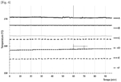
- FIG.4 illustrates an example of temperature distribution in an enclosure of a device according to an embodiment of the invention.
- the container 1 has a first height of 49 cm.
- the enclosure 2 has a second height of 135 cm.
- the second heating means 20 heats the upper zone 21 of the enclosure and, to a lesser extent, the lower zone 22 of the enclosure.
- the third heating means 30 heats the bottom of the container 1. Part of the heat spreads towards the top of the container by thermal conduction.
- the curves give the evolution over time of temperatures at different levels on the container 1 and on the distribution means 13 and 14 along the axial direction z.
- Curve A corresponds to a temperature measurement at a dispensing means 13 arranged at a distance of the order of 60 cm above the top of the container 1.
- Curve B corresponds to a temperature measurement at a valve 14 arranged at a distance of the order of 13 cm above the top of the container 1.
- Curve C corresponds to a temperature measurement at the top of the container 1.
- Curve D corresponds to a temperature measurement in the middle of the height of the container 1.
- Curve E corresponds to a temperature measurement at a distance of 5 cm above the bottom of the container 1.
- Curve F corresponds to a temperature measurement measured at the bottom of the container 1.
- a heat transfer takes place by convection between the hot air contained in the enclosure 2 and the container 1 and the distribution means 13 and 14 when using the second heating means 20.
- natural convection alone may not be sufficient to provide the energy necessary to ensure the desired gas phase flow rates on an industrial scale, in particular for chemical vapor deposition applications where the desired deposition rates are increasingly high.
- the first, second and/or third heating means can heat the container 1 so that the vapor pressure of the precursor increases.
- the second means is used in particular to generate the temperature profile.
- the third means can be used to adjust this profile.
- the first, second and/or third heating means act as complementary means to adapt the temperature profile as best as possible to the conditions of use.
- the heating medium that predominates in the heat input required to achieve the desired pressure and ensure the desired precursor flow rate may depend on the conditions of use of the device. In particular, it may depend on the filling level of the container 1 and the contact surface of the precursor with the surrounding volume. When the container 1 is full, the first heating means and the second heating means have the most influence. When the container 1 is relatively little filled, or even almost empty, the third heating means has the most influence in heating the precursor.
- the heated solid precursor 11 sublimes using the available energy supplied by the various heating means to the container 1.
- the distribution rate of the pure precursor is conditioned by its sublimation speed. The higher the withdrawal rate required, the greater the energy requirement and the more the container must be heated. The same is true when it is desired to increase the pressure of the fluid distributed by the container due to a higher pressure required at the point of use. In both cases, it is necessary to increase the heat transferred by the first heating means. Furthermore, if the consumption rate of the precursor vapors decreases at the point of use, it is also necessary to reduce the heating of the container 1 in order to reduce the quantity of gaseous phase 12 sublimed.
- the first heating means 10 are configured to deliver a variable heating power.
- the heating means 10 are connected to an electrical power supply member and the heating power varies according to the intensity of the supply current applied to the first heating means 10.
- the device further comprises at least one pressure sensor PC configured to measure the pressure inside the container 1.
- the pressure sensor PC is fluidically connected to the interior volume of the container 1.
- the pressure sensor PC can be mounted at the distribution means 13, 14, preferably downstream of the outlet of a valve 14 controlling the distribution of the gas phase 12, said valve being arranged downstream of the outlet 17 or between the outlet 17 of the container 1 and the valve 14, or directly on the container 1.
- the pressure sensor can also be located outside the enclosure and be fluidically connected to the container 1.
- a control unit 40 is connected to the pressure sensor PC and to the first heating means 10. The control unit 40 is configured to vary the heating power delivered by the first heating means 10 as a function of the pressure measured by the pressure sensor PC.
- the second heating means advantageously continues to heat the internal volume of the enclosure 2 and the container 1.
- the heating power is thus adapted to adapt the temperature to which the precursor is heated in container 1 in order to stabilize the pressure in container 1.
- the control unit adapts the heating conditions by the first means 10 so as to adjust the pressure in the container. This ensures continuous distribution with a stable gas phase flow rate. This mode of regulation is more efficient and safer than independent regulation of the first heating means since a pressure variation directly and immediately reflects the state of the physical system in the container 1.
- This embodiment is suitable for the case where the precursor is dispensed pure, since the pressure in the container 1 corresponds to the gas phase pressure 12 and directly reflects the amount of precursor that can be sublimed.
- control unit 40 is configured to compare the pressure measured inside the container 1 with a set pressure.
- the heating power is increased when the pressure measured inside the container 1 is lower than the set pressure.
- the heating power is reduced when the pressure measured inside the container 1 is greater than or equal to the set pressure. Note that the reduction in the heating power means heating at a lower power or stopping the heating, depending on the pressure difference calculated by the control unit 40 between the pressure setpoint and the measured system pressure.
- the setpoint pressure may be predefined depending in particular on the operating conditions of the installation, the components of the installation, the pressure and flow rate required at the point of use and/or the nature of the precursor, each precursor molecule having a specific curve of variation of its saturated vapor pressure as a function of temperature.
- the setpoint pressure is defined and the first heating means 10 are configured so that, when they operate at a so-called nominal power, the precursor is heated to a temperature at which its saturated vapor pressure is equal to the setpoint pressure. The greater the difference between the setpoint pressure and the pressure measured in the container 1, the more the power of the first heating means is increased compared to the nominal power.
- control unit 40 may further be configured to compare the pressure measured inside the container 1 with a high pressure threshold.
- the device may comprise a vent line with a vent associated with a valve or a vacuum network 61 fluidly connected to the container 1, and at least one valve controlling the passage of the fluid to the vacuum network. If the pressure measured by the pressure sensor PC is greater than the high pressure threshold, the control unit 40 commands the opening of this valve or this valve, which makes it possible to reduce the pressure in the container 1 more quickly and to provide additional safety.
- the [ Fig.4 ] represents an exemplary embodiment in which the pressure is released using a three-way valve connected to a vacuum line 61.
- the device may comprise a purge pipe 63 fluidly connected to the container 1 and to the distribution means 13, 14 so as to convey a purge gas thereto. This makes it possible, during the start-up or maintenance phases, to purge the pipes of the device and the container 1.
- the regulation of the heating of the container 1 as a function of the pressure also makes it possible to adapt the temperature to which the container 1 is heated as a function of the gas phase flow rate requested at the point of use 60.
- the control unit 40 orders an increase in the heating power in order to increase the saturated vapor pressure and to sublime more precursor. If the flow rate and/or the pressure requested at the point of consumption decreases, this results in an increase in the pressure measured by the sensor PC due to the excess sublimed precursor.
- the control unit 40 orders a decrease in the heating power in order to sublime less precursor and/or the opening of the valve or the valve going to the vacuum network 61 if the high pressure threshold is exceeded.
- control loop is generally meant a system for controlling a process in which a regulating variable acts on a controlled variable, i.e. a variable to be controlled, to bring it as quickly as possible to a setpoint value and maintain it there.
- the basic principle of a control is to continuously measure the difference between the actual value of the variable to be controlled and the setpoint value that it is desired to achieve, and to calculate the appropriate command to be applied to one or more actuators so as to reduce this difference as quickly as possible. This is also referred to as a closed-loop controlled system.
- the controlling variable is the pressure measured by the sensor PC
- the controlled variable is the heating power of the container 1, and therefore indirectly the heating temperature of the solid phase 11, via the adjustment of the power of the first heating means 10.
- control loop comprises a comparator arranged within the control unit 40 and configured to generate at least one error signal from the comparison between the measured pressure and the pressure setpoint.
- the loop comprises a corrector configured to generate the control signal from the error signal.
- the corrector sends the control signal to the unit 40 which controls the adjustment of the heating power.
- the corrector is of the proportional, integral and derivative (PID) type, which makes it possible to improve the performance. of a control thanks to three combined actions: a proportional action, an integral action, a derivative action.
- the proportional, integral, and derivative terms can be determined by calculation and/or experimentally.
- the derivative term of D can possibly be zero.
- control unit 40 comprises a programmable logic controller, also called a “PLC” system for “Programmable Logic Controller” in English, that is to say a system for controlling an industrial process comprising a human-machine interface for supervision and a digital communication network.
- PLC programmable logic controller
- the PLC system may comprise several modular controllers which control the subsystems or control equipment of the device. These equipments are each configured to ensure at least one operation among: the acquisition of data from at least one measurement sensor, the control of at least one actuator connected to at least one flow or pressure controller member, the regulation and control of parameters, the transmission of data between the different equipments of the system.
- the control unit 40 can thus comprise at least one of: a microcontroller, a microprocessor, a computer.
- the control unit 40 can be connected to the various control equipment of the device, in particular to the flow rate and pressure regulating members, to the sensors, to the heating means control members, and communicate with said equipment by electrical connections, Ethernet, Modbus, etc.
- Other modes of connection and/or transmission of information are conceivable for all or part of the equipment of the device, for example by radiofrequency connections, WIFI, Bluetooth, etc.
- control unit 40 comprises a human-machine interface comprising an input interface, for example a touch screen, allowing a user to enter instructions intended for the control unit 40 and/or data relating in particular to the nature of the precursor, the desired flow rate and/or distribution pressure, the treatment installation, etc.
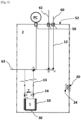
- FIG.2 illustrates an embodiment in which the device is intended to distribute a gaseous phase 12 diluted in a carrier gas 4. Note that all or part of the characteristics described previously can be transposed to the case of the distribution of the diluted gaseous phase, in particular the characteristics relating to the control unit, the regulation loop, the enclosure, the second heating means, etc.
- the device comprises carrier gas circulation means 41, 42 configured to circulate the carrier gas 4 between the inlet 16 and the outlet 17 of the container 1 so that the carrier gas 4 becomes charged in gas phase 12 when it circulates in the container 1. A mixture of precursor and carrier gas is thus distributed to the point of use.
- the device according to the invention can in particular be used to produce mixtures of precursor vapors and carrier gas having precursor contents of between 1 ppmm and 10%, preferably between 50 ppmm and 5% (ppm and % by mass), the remainder being the carrier gas.
- precursor contents of between 1 ppmm and 10%, preferably between 50 ppmm and 5% (ppm and % by mass), the remainder being the carrier gas.
- mixtures having the following compositions can be distributed: 1700 ppm of WCl 5 in N 2 , 3.5% of WCl 6 in N 2 .
- the carrier gas circulation means 41, 42 are configured to regulate the flow rate of carrier gas 4 sent into the container 1 and/or to regulate the pressure in the container 1.
- the carrier gas circulation means 41, 42 may comprise at least one of: an upstream flow regulator 41 arranged upstream of the container 1 so as to regulate the flow rate of the carrier gas 4 flowing to the container 1, an upstream pressure regulator 41 arranged upstream of the container 1 so as to regulate the pressure in the container 1, a downstream flow regulator 42 arranged downstream of the container 1 so as to regulate the flow rate of the gas mixture flowing from the container 1, a downstream pressure regulator 42 arranged downstream of the container 1 for regulating the pressure in the container 1.
- the upstream pressure regulator 41, 42 is configured to regulate the flow rate of the carrier gas 4 sent to the container 1 and/or to regulate the pressure in the container 1.
- pressure 42 can be a flow controller (used to control pressure), a relief valve, a back pressure regulator, a butterfly valve...
- the supply line 15 may be provided with a pressure reducer 41 and/or the distribution line 13 may be provided with a relief valve 42 in order to regulate the pressure in the container 1.
- the relief valve 42 operates as an upstream pressure regulator, that is to say it is configured to regulate the pressure of the fluid in the gas circuit upstream of the relief valve 42.
- the use of the relief valve 42 makes it possible to maintain the upstream pressure constant, while the downstream pressure may fluctuate.
- the relief valve may comprise a chamber mounted in a bypass, a valve controlled by a control membrane. This membrane is balanced on the one hand by a calibrated spring provided to close and open a conduit connected to the gas circuit and on the other hand by the pressure to be stabilized upstream.
- the pressure in the container may by example be kept constant, in particular at a value between 67 mbara and 2 bara (absolute bar).
- the device may comprise at least one pressure reducer 41 which operates as a downstream pressure reducer.
- the pressure reducer 41 is configured to regulate the pressure of the distributed mixture and ensures the stability of the pressure at the point of use of the mixture in order to meet the requirements of the treatment installation in terms of precision and stability of the parameters of the mixture.
- the pressure reducer 41 may be mounted in series on the pipe 15.
- the supply line 15 may be provided with a flow regulator 41 and/or the distribution line 13 may be provided with a flow regulator 42 in order to regulate the flow rate of carrier gas 4 passing through the container 1.
- Each flow regulator member 41, 42 may be any means configured to regulate, regulate, adjust the flow rate of a fluid to bring it to a flow rate value closest to the desired value.
- the flow regulator members 41, 42 each comprise a flow meter, associated with an expansion member, such as a valve, for example a proportional adjustment valve.
- the valve comprises a movable part, typically at least one shutter, which is placed in the fluid flow and the movement of which makes it possible to vary the passage section, and thus to vary the flow rate to bring it to the set value.
- the concentration of the gaseous phase of the precursor in the carrier gas is determined by the ratio between the flow rate of sublimed precursor and the flow rate of carrier gas.
- the stability of the concentration of the gaseous phase of the precursor in the carrier gas is ensured by the saturation of the carrier gas in the container 1 and by the stability of the temperature of the container 1.
- the stability of the flow rate of mixture distributed at the point of use is thus ensured by the stability of the flow rate of carrier gas circulating in the container 1.
- the control unit 40 can thus be connected to the previously described regulating organs so as to control their operation, in particular so as to adjust the setpoint values applied to them to bring them to values determined as a function of the operating conditions of the installation.
- the device advantageously comprises at least one temperature sensor TC configured to measure the temperature of an external surface of the container 1.
- the sensor TC may be any sensor configured to carry out temperature measurements by contact, in particular a resistance temperature sensor, for example a platinum resistance sensor of the PT100 type, or a thermocouple or thermistor temperature probe.
- the temperature sensor TC is configured to measure the temperature of at least a portion of the outer surface of a wall of the container 1, preferably the peripheral wall located between the bottom and the top.
- the TC sensor is arranged at a height of the container at which the first heating means 10 extends. This provides greater precision and speed of regulation.
- the control unit 40 is connected to the temperature sensor TC and to the first heating means 10, the control unit 40 being configured to vary the heating power delivered by the first heating means 10 as a function of the temperature measured by the temperature sensor TC.
- control unit 40 comprises means for comparing the temperature measured by the TC sensor with a third temperature setpoint of a predetermined value.
- the control unit 40 is configured to reduce the heating power when the measured temperature is higher than the third temperature setpoint and to increase the heating power when the measured temperature is lower than the third temperature setpoint.
- the reduction in the heating power means heating at a lower power or stopping the heating depending on the temperature difference calculated by the control unit 40 between the third temperature setpoint and the measured temperature.
- the temperature to which the container 1 is heated is stabilized at its set value. This ensures continuous distribution with a stable gas phase flow rate.
- This embodiment is suitable for the case where the precursor is distributed diluted since in this case, the pressure in the container 1 is a function of the pressure of the carrier gas 4 and the temperature of the precursor.
- the third temperature setpoint can be defined in particular as a function of the operating conditions and the components of the installation, the pressure, the flow rate required at the point of use and/or the nature of the precursor.
- the first heating means 10 are configured so that, when they operate at a so-called nominal power, the surface temperature of the container measured by the TC sensor is equal to the third temperature setpoint.
- the third setpoint is determined so that the precursor vapor concentration in the carrier gas satisfies the specifications of the treatment installation. If the treatment installation requires a high concentration of precursor, the third temperature setpoint will be increased in order to increase the saturated vapor pressure of the precursor. If the treatment installation requires a lower concentration of precursor, the setpoint will be reduced to decrease the saturated vapor pressure of the precursor.
- the device according to the invention can comprise both a pressure sensor PC and a temperature sensor TC as described previously. This allows with the same device to be able to operate a regulation of the heating power in a pure precursor distribution mode or in a diluted precursor distribution mode.
- the control unit 40 is configured to develop heating power control signals from measurements coming from one or other of the sensors.
- the distribution means 13, 14 comprise at least one distribution pipe 13 passing through a first wall 52 of the enclosure 2.
- the device may further comprise at least one heating element 50 forming a sleeve around at least part of the distribution pipe 13 and extending on either side of said first wall 52.
- the wall passages can form cold spots on the path of the gas phase 12, which creates a risk of recrystallization of the gas phase at the wall passages.
- one or more heating elements are inserted into the walls of the enclosure and the distribution pipe is heated at the level of its passage in the wall so as to avoid recrystallization of the sublimed precursor and to maintain an increasing temperature along the axial direction z.
- the heating element 50 may comprise two heating half-shells formed from a thermally conductive material.
- the half-shells may contain one or more heating cartridges as well as at least one temperature probe.
- the shells are inserted into the wall of the enclosure and are heated, preferably at a constant temperature.
- the distribution device further comprises at least one additional enclosure 3 having a second wall 53 arranged opposite the first wall 52 of the enclosure 2.
- the distribution pipe 13 conveying the precursor vapors from the container 1 passes through the second wall 53 of the additional enclosure 3 and distributes the vapors to the point of use 60.
- the additional enclosure 3 is not necessarily positioned above the enclosure 2 but that other arrangements are possible, depending on the location of the point of use and the available footprint.
- the additional enclosure 3 comprises third heating means configured to heat at least part of the internal volume of the additional enclosure 3 to temperatures higher than the temperatures of the enclosure 2. An increase in temperature is thus observed along the axial direction z in order to avoid recrystallization. of the product in the lines of the enclosure 3.
- a heating element 50 as described previously is arranged around the distribution pipe 13 at the level of its passage through the second wall 53.
- a distribution assembly is produced with at least two distribution devices according to the invention arranged in parallel. More precisely, each device comprises a container 1 and respective distribution means 13, 14 fluidly connected to a common pipe 19, itself connected to the consumption point 60. Note that the arrangement of an additional enclosure 3 is optional.
- the assembly comprises tilting means configured to occupy a first position in which the gas phase 12 is distributed into the common pipe 19 from one of the two containers.
- the tilting means may comprise the valves 14 of the respective distribution means 13, 14 and/or additional valves connected to the distribution means such as elbow valves, as visible in [ Fig.7 ].
- the switching from one source to the other is done automatically, that is to say without intervention of an operator.
- the switching means are moved into a second position in which the gas phase 12 is distributed into the common pipe 19 from the other of the two containers 1.
- the movement of the switching means from the first position to the second position is triggered from the measurement of a physical quantity representative of the quantity of precursor in the container 1 which can be chosen from: the mass of the container 1, the pressure in the container 1, the temperature of an external surface of the container 1.
- the pressure in container 1 is measured. If the pressure falls below a given threshold, this means that there is no longer enough solid phase in the container to maintain the pressure setpoint. This triggers the movement of the tilting means.
- the temperature of an outer surface of the container 1 is measured, i.e. the skin temperature of the container 1. If the temperature exceeds a given threshold, this means that there is no longer enough precursor in the container and that the temperature of the first heating means 10 is increased in order to maintain the pressure setpoint. This triggers the movement of the tilting means.
- the advantage of a system with several distribution devices is that it allows continuous operation of the treatment plant using the precursor, despite the exhaustion of one container. In fact, when the container in use reaches the low threshold, the other container can be used while the empty container is replaced by a new full container.
- the tilting means may occupy an intermediate position in which the gas phase 12 is distributed from both containers simultaneously, before tilting to the other container. This makes it possible to avoid pressure drops when opening the valves of the second container 1 and to completely empty the first container in order to increase the efficiency of use.
- the main enclosures 2 making up the distribution assembly are arranged side by side and an additional enclosure 3 is arranged above the main enclosures 2.
- the internal volume of the additional enclosure 3 is heated to a temperature higher than the temperature to which the volume of the main enclosures 2 is heated, always to respect the direction of temperature variation increasing upwards.
- Heating elements 50 are arranged at the wall passages from each enclosure 2 to the additional enclosure 3.
- the device comprises at least one gas cabinet in which one or more enclosures 2, 3 can be installed.
- the source of carrier gas can be located inside or outside the cabinet depending on the available space.
- the control unit 40 can be arranged inside or outside the cabinet, either by being fixed to one of the walls of the cabinet or positioned at a distance from the cabinet.
- a gas pipe system is arranged in the cabinet.
- the cabinet may include means for controlling and/or maintaining the gas pipe system such as valves, pressure regulators, pressure measuring devices, etc., enabling operations to be carried out such as gas distribution, opening or closing of certain pipes or portions of pipes, gas pressure management, carrying out purge cycles, leak tests, etc.
- the cabinet may include gas inlet openings for supplying with the carrier gas and a gas outlet opening for distributing the gaseous phase.
- the distribution pipe 13 is connected to the outlet opening.
- the gas cabinet is connected to the treatment installation via the consumption point 60.
- Other gas inlets may be provided, in particular for a sweep gas, a standard gas....
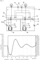
- MoO 2 Cl 2 was distributed as a pure precursor at a mass flow rate of 900 cm 3 /min standard (i.e. sccm for "standard cubic centimeters per minute") and a pressure of 650 Torr.
- the set pressure was 650 Torr.
- the first, second and third heating means 10, 20, 30 were implemented in such a way.
- the container 1 and the distribution means 13, 14 had a temperature profile as illustrated in [ Fig.4 ].
- [ Fig.8 ] shows a flow rate change at 11min from 0 sccm to 900 sccm of MoO2Cl2.
- the precursor is flowed for 71min, then the flow is stopped.
- [ Fig.8 ] also shows the system pressure and the power of the first heater 10. It can be seen that when going from 0 to 900 sccm, the system pressure decreases from 650 Torr (pressure setpoint) to 580 Torr. Due to the decrease in system pressure, the power of the first heater 10 increases from 2% to 100%. Due to the heating of the first heater 10, the system pressure increases to 700 Torr.
- the heating of the first heater is decreased when the pressure rises and approaches the setpoint pressure of 650 Torr and is stopped when the pressure exceeds the pressure setpoint.
- the system pressure then stabilizes around the pressure setpoint. It can be seen that the amplitude of the pressure oscillations decreases.
- the precursor flow is stopped when the system pressure is not yet stabilized, but a pressure variation of 1.5% is reached in 71 min.
- the device according to the invention can be used for the distribution of precursors used in different industries such as the semiconductor, photovoltaic, LED, flat screen or any other industry such as the mining, pharmaceutical, space or aeronautical industries.
Landscapes
- Chemical & Material Sciences (AREA)
- Chemical Kinetics & Catalysis (AREA)
- General Chemical & Material Sciences (AREA)
- Engineering & Computer Science (AREA)
- Materials Engineering (AREA)
- Mechanical Engineering (AREA)
- Metallurgy (AREA)
- Organic Chemistry (AREA)
- Physical Or Chemical Processes And Apparatus (AREA)
- Chemical Vapour Deposition (AREA)
- Feeding, Discharge, Calcimining, Fusing, And Gas-Generation Devices (AREA)
Claims (11)
- Vorrichtung zur Abgabe einer Gasphase mindestens eines festen Vorläufers, die Vorrichtung umfassend:- einen Behälter (1), der dazu bestimmt ist, eine feste Phase (11) des Vorläufers zu enthalten, wobei der Behälter einen Boden und einen Kopf aufweist,- ein erstes Heizmittel (10), das dazu ausgestaltet ist, mindestens einen Teil des Behälters (1) und/oder der festen Phase (11) zu erhitzen, so dass eine Gasphase (12) des Vorläufers in dem Behälter (1) gebildet wird,- Abgabemittel (13, 14), die fluidisch mit dem Behälter (1) verbunden sind und dazu ausgestaltet sind, die Gasphase (12) von dem Behälter (1) aus zu einer Verwendungsstelle (60) abzugeben,dadurch gekennzeichnet, dass die Vorrichtung eine Einhausung (2) umfasst, die ein Innenvolumen besitzt, in dem der Behälter (1), das erste Heizmittel (10) und die Abgabemittel (13, 14) angeordnet sind, wobei die Einhausung (2) eine im Wesentlichen vertikale und aufsteigend ausgerichtete axiale Richtung (z) aufweist, wobei das Innenvolumen der Einhausung (2) einen unteren Bereich (22) und einen oberen Bereich (21) umfasst, wobei die Vorrichtung ferner ein zweites Heizmittel (20) umfasst, das dazu ausgestaltet ist, mindestens einen Teil des Innenvolumens der Einhausung (2) zu erhitzen, wobei das zweite Heizmittel (20) ein Luftzirkulationsmittel (24) umfasst, das dazu ausgestaltet ist, Luft von dem zweiten Heizmittel (20) aus in Richtung des Innenvolumens der Einhausung (2) zirkulieren zu lassen.
- Vorrichtung nach dem vorhergehenden Anspruch, dadurch gekennzeichnet, dass der obere Bereich (21) auf einer höheren Ebene als der untere Bereich (22) entlang der axialen Richtung (z) angeordnet ist, wobei der erste Behälter (1) und das erste Heizmittel (10) in dem unteren Bereich (22) angeordnet sind und wobei das zweite Heizmittel (20) und die Abgabemittel (13, 14) in dem oberen Bereich (21) angeordnet sind.
- Vorrichtung nach einem der vorhergehenden Ansprüche, dadurch gekennzeichnet, dass sie ferner ein drittes Heizmittel umfasst, das in dem unteren Bereich (22) der Einhausung (2) angeordnet ist, bevorzugt um mindestens einen Teil des Bodens (1a) des Behälters (1) herum oder unter dem Boden (1a) des Behälters (1).
- Vorrichtung nach einem der vorhergehenden Ansprüche, dadurch gekennzeichnet, dass das zweite Heizmittel (20) mindestens einen elektrischen Widerstand umfasst, der insbesondere an einer Wand der Einhausung (2) oder in der Nähe der Wand angebracht ist.
- Vorrichtung nach einem der vorhergehenden Ansprüche, dadurch gekennzeichnet, dass die Vorrichtung mindestens einen Drucksensor (PC) umfasst, der dazu ausgestaltet ist, den Druck im Inneren des Behälters (1) zu messen, und eine Steuerungseinheit (40), die mit dem Drucksensor (PC) und mit dem ersten Heizmittel (10) verbunden ist, wobei die Steuerungseinheit (40) insbesondere dazu ausgestaltet ist, die von dem ersten Heizmittel (10) ausgegebene Heizleistung in Abhängigkeit von dem von dem Drucksensor (PC) gemessenen Druck zu regulieren und/oder anzupassen.
- Vorrichtung nach einem der vorhergehenden Ansprüche, dadurch gekennzeichnet, dass sie ferner eine Quelle für Trägergas (4), eine Versorgungsleitung (15), die die Quelle für Trägergas (4) fluidisch mit einem Einlass (16) des Behälters (1) verbindet, und Zirkulationsmittel (41, 42) für das Trägergas (4) in dem Behälter (1) umfasst, wobei die Zirkulationsmittel (41, 42) für das Trägergas dazu ausgestaltet sind, das Trägergas (4) zwischen dem Einlass (16) und einem Auslass (17) des Behälters (1) zirkulieren zu lassen, so dass die Abgabemittel (13, 14) ein Gasgemisch, das die Gasphase (12) und das Trägergas (4) umfasst, von dem Behälter (1) aus abgeben, wobei die Zirkulationsmittel (41, 42) für das Trägergas insbesondere dazu ausgestaltet sind, den Volumenstrom des Trägergases (4), das in dem Behälter (1) zirkuliert, zu steuern und/oder den Druck in dem Behälter (1) zu steuern.
- Vorrichtung nach einem der vorhergehenden Ansprüche, dadurch gekennzeichnet, dass die Vorrichtung mindestens einen Temperatursensor (TC) umfasst, der dazu ausgestaltet ist, die Temperatur einer Außenfläche des Behälters (1) zu messen und/oder die Temperatur im Inneren der Einhausung zu messen, und eine Steuerungseinheit (40), die mit dem Temperatursensor (TC) und mit dem ersten Heizmittel (11) verbunden ist, wobei die Steuerungseinheit (40) insbesondere dazu ausgestaltet ist, die von dem ersten Heizmittel (10) ausgegebene Heizleistung in Abhängigkeit von dem von der Temperatursensor (TC) gemessenen Temperatur variieren zu lassen.
- Vorrichtung nach einem der vorhergehenden Ansprüche, dadurch gekennzeichnet, dass die Abgabemittel (13, 14) mindestens eine Abgabeleitung (13) umfassen, die eine erste Wand (52) der Einhausung (2) durchdringt, wobei ein Heizelement (50) eine Hülse um mindestens einen Teil der Abgabeleitung (13) bildet und sich beidseits der ersten Wand (52) erstreckt.
- Abgabeanordnung, umfassend mindestens zwei Vorrichtungen zur Abgabe wie in einem der Ansprüche 1 bis 8 definiert, jede Vorrichtung umfassend eine Einhausung (2), einen Behälter (1) und jeweilige Abgabemittel (13, 14), die fluidisch mit einer gemeinsamen Leitung (19) verbunden sind, die Anordnung umfassend Umschaltmittel, die dazu ausgestaltet sind, eine erste Stellung einzunehmen, in der die Gasphase (12) ausgehend von dem einen der beiden Behälter in die gemeinsame Leitung (19) abgegeben wird, und, wenn die Vorläufermenge in dem Behälter (1) kleiner oder gleich einem vorbestimmten unteren Schwellenwert ist, eine zweite Stellung einzunehmen, in der die Gasphase (12) ausgehend von dem anderen der beiden Behälter (1) in die gemeinsame Leitung (19) abgegeben wird, oder eine Zwischenstellung einzunehmen, in der die Gasphase (12) ausgehend von den beiden Behältern gleichzeitig abgegeben wird, wobei die Umschaltmittel mit einem Organ zum Messen einer physikalischen Größe verbunden sind, die für die Vorläufermenge in dem Behälter (1) repräsentativ ist und ausgewählt ist unter: der Masse des Behälters (1), dem Druck in dem Behälter (1), der Temperatur einer Außenfläche des Behälters (1), wobei die Verlagerung der Umschaltmittel aus der ersten Stellung in die zweite Stellung in Abhängigkeit von der Messung der physikalischen Größe bestimmt wird.
- Anlage zur Behandlung, insbesondere zur chemischen Gasphasenabscheidung, umfassend eine Behandlungskammer, in der ein oder mehrere zu behandelnde Substrate eingerichtet sind, wobei die Behandlungskammer Mittel zum Einleiten mindestens einer Gasphase (12) eines festen Vorläufers in die Behandlungskammer umfasst, dadurch gekennzeichnet, dass die Mittel zum Einleiten fluidisch mit den Abgabemitteln (13, 14) einer Vorrichtung wie in einem der Ansprüche 1 bis 8 definiert oder einer Anordnung wie in Anspruch 9 definiert verbunden sind.
- Verfahren zur Abgabe einer Gasphase mindestens eines festen Vorläufers, umfassend die folgenden Schritte:a) Anordnen einer festen Phase (11) des Vorläufers in einem Behälter (1),b) Erhitzen mindestens eines Teil des Behälters (1) und/oder der festen Phase (11) mit einem ersten Heizmittel (10), so dass eine Gasphase (12) des Vorläufers in dem Behälter (1) gebildet wird,c) Abgeben der Gasphase (12) von dem Behälter (1) aus durch Abgabemittel (13, 14), die fluidisch mit dem Behälter (1) verbunden sind,wobei das Verfahren ferner die Schritte umfasst:d) Anordnen des Behälters (1), des ersten Heizmittels (10) und der Abgabemittel (13, 14) in einem Innenvolumen einer Einhausung (2), wobei die Einhausung (2) eine im Wesentlichen vertikale und aufsteigend ausgerichtete axiale Richtung (z) aufweist, wobei das Innenvolumen der Einhausung (2) einen unteren Bereich (22) und einen oberen Bereich (21) umfasst,e) Erhitzen mindestens eines Teils des Innenvolumens der Einhausung (2) mit einem zweiten Heizmittel (20), wobei das zweite Heizmittel (20) ein Luftzirkulationsmittel (24) umfasst, das dazu ausgestaltet ist, Luft von dem zweiten Heizmittel (20) aus in Richtung des Innenvolumens der Einhausung (2) zirkulieren zu lasen.
Applications Claiming Priority (2)
| Application Number | Priority Date | Filing Date | Title |
|---|---|---|---|
| FR2105994A FR3123660B1 (fr) | 2021-06-07 | 2021-06-07 | Dispositif et procédé de distribution d’une phase gazeuse d’un précurseur solide |
| PCT/EP2022/060165 WO2022258247A1 (fr) | 2021-06-07 | 2022-04-15 | Dispositif et procédé de distribution d'une phase gazeuse d'un précurseur solide |
Publications (2)
| Publication Number | Publication Date |
|---|---|
| EP4352276A1 EP4352276A1 (de) | 2024-04-17 |
| EP4352276B1 true EP4352276B1 (de) | 2025-06-04 |
Family
ID=77021511
Family Applications (1)
| Application Number | Title | Priority Date | Filing Date |
|---|---|---|---|
| EP22723129.7A Active EP4352276B1 (de) | 2021-06-07 | 2022-04-15 | Vorrichtung und verfahren zur abgabe einer gasphase eines festen vorläufers |
Country Status (7)
| Country | Link |
|---|---|
| US (1) | US20240368758A1 (de) |
| EP (1) | EP4352276B1 (de) |
| JP (1) | JP2024521699A (de) |
| KR (1) | KR20240018475A (de) |
| CN (1) | CN117321245A (de) |
| FR (1) | FR3123660B1 (de) |
| WO (1) | WO2022258247A1 (de) |
Family Cites Families (7)
| Publication number | Priority date | Publication date | Assignee | Title |
|---|---|---|---|---|
| EP0382987A1 (de) * | 1989-02-13 | 1990-08-22 | L'air Liquide, Societe Anonyme Pour L'etude Et L'exploitation Des Procedes Georges Claude | Gasversorgungsanlage |
| JPH0499178A (ja) * | 1990-08-02 | 1992-03-31 | Nippon Sanso Kk | Cvd装置 |
| US9034105B2 (en) | 2008-01-10 | 2015-05-19 | American Air Liquide, Inc. | Solid precursor sublimator |
| GB0802687D0 (en) * | 2008-02-14 | 2008-03-19 | P2I Ltd | Vapour delivery system |
| GB201307073D0 (en) * | 2013-04-19 | 2013-05-29 | Fernandez Ivan | Pulsed valve cracker effusion cell |
| US11421320B2 (en) * | 2017-12-07 | 2022-08-23 | Entegris, Inc. | Chemical delivery system and method of operating the chemical delivery system |
| US11624113B2 (en) * | 2019-09-13 | 2023-04-11 | Asm Ip Holding B.V. | Heating zone separation for reactant evaporation system |
-
2021
- 2021-06-07 FR FR2105994A patent/FR3123660B1/fr active Active
-
2022
- 2022-04-15 WO PCT/EP2022/060165 patent/WO2022258247A1/fr not_active Ceased
- 2022-04-15 KR KR1020237042309A patent/KR20240018475A/ko active Pending
- 2022-04-15 CN CN202280035274.7A patent/CN117321245A/zh active Pending
- 2022-04-15 EP EP22723129.7A patent/EP4352276B1/de active Active
- 2022-04-15 US US18/567,897 patent/US20240368758A1/en active Pending
- 2022-04-15 JP JP2023571774A patent/JP2024521699A/ja active Pending
Also Published As
| Publication number | Publication date |
|---|---|
| US20240368758A1 (en) | 2024-11-07 |
| FR3123660B1 (fr) | 2024-02-16 |
| FR3123660A1 (fr) | 2022-12-09 |
| JP2024521699A (ja) | 2024-06-04 |
| KR20240018475A (ko) | 2024-02-13 |
| CN117321245A (zh) | 2023-12-29 |
| WO2022258247A1 (fr) | 2022-12-15 |
| EP4352276A1 (de) | 2024-04-17 |
Similar Documents
| Publication | Publication Date | Title |
|---|---|---|
| KR102387359B1 (ko) | 자동-리필 앰풀 및 사용 방법들 | |
| US8137468B2 (en) | Heated valve manifold for ampoule | |
| RU2503744C2 (ru) | Устройство и способ для реакторов осаждения (варианты) | |
| US5203925A (en) | Apparatus for producing a thin film of tantalum oxide | |
| EP2247769B1 (de) | Sublimator für feste vorstufe | |
| JP5895712B2 (ja) | 原料ガス供給装置、成膜装置、原料ガスの供給方法及び記憶媒体 | |
| KR20100063694A (ko) | 원료 가스의 공급 시스템 및 성막 장치 | |
| CN106103795A (zh) | 蒸气输送系统 | |
| EP2350341B1 (de) | Vorrichtung zur synthese von nanopartikeln durch wirbelschicht-cvd | |
| EP4352276B1 (de) | Vorrichtung und verfahren zur abgabe einer gasphase eines festen vorläufers | |
| EP4454083B1 (de) | Installation und verfahren zur verteilung eines dielektrischen gassgemischs zu einer gasisolierten schaltanlage | |
| KR102770119B1 (ko) | 기체상태 화학약품 공급라인의 퍼지시스템 | |
| WO2020161434A1 (fr) | Réservoir de propulseur avec système de commande marche-arrêt du flux de gaz, propulseur et engin spatial intégrant un tel système de commande | |
| JP2013028854A (ja) | 固体材料ガスの供給装置および供給方法 | |
| WO2021245000A1 (fr) | Installation et procédé de distribution d'un mélange de gaz | |
| JP2013189662A (ja) | 薄膜形成装置 | |
| FR2894165A1 (fr) | Installation d'alimentation en gaz pour machines de depot d'une couche barriere sur recipients | |
| JP4421119B2 (ja) | 半導体装置の製造方法 | |
| FR2956412A1 (fr) | Vanne d'obturation a volume constant d'une source de depot en phase vapeur | |
| JP5144268B2 (ja) | 有機材料の気化を制御するための方法と装置 | |
| US20030056728A1 (en) | Method and device for depositing at least one precursor, which is in liquid or dissolved form, on at least one substrate | |
| TW201627060A (zh) | 固態來源蒸氣輸送封裝及方法 | |
| EP4453684A1 (de) | Anlage und verfahren zur konditionierung eines gasgemisches | |
| JP2004514997A (ja) | 低容量液体流の計量化送出のための方法および装置 | |
| EP4162520A1 (de) | Anlage und verfahren zur verteilung eines gasgemisches zur dotierung von siliziumwafern |
Legal Events
| Date | Code | Title | Description |
|---|---|---|---|
| STAA | Information on the status of an ep patent application or granted ep patent |
Free format text: STATUS: UNKNOWN |
|
| STAA | Information on the status of an ep patent application or granted ep patent |
Free format text: STATUS: THE INTERNATIONAL PUBLICATION HAS BEEN MADE |
|
| PUAI | Public reference made under article 153(3) epc to a published international application that has entered the european phase |
Free format text: ORIGINAL CODE: 0009012 |
|
| STAA | Information on the status of an ep patent application or granted ep patent |
Free format text: STATUS: REQUEST FOR EXAMINATION WAS MADE |
|
| 17P | Request for examination filed |
Effective date: 20240108 |
|
| AK | Designated contracting states |
Kind code of ref document: A1 Designated state(s): AL AT BE BG CH CY CZ DE DK EE ES FI FR GB GR HR HU IE IS IT LI LT LU LV MC MK MT NL NO PL PT RO RS SE SI SK SM TR |
|
| DAV | Request for validation of the european patent (deleted) | ||
| DAX | Request for extension of the european patent (deleted) | ||
| GRAP | Despatch of communication of intention to grant a patent |
Free format text: ORIGINAL CODE: EPIDOSNIGR1 |
|
| STAA | Information on the status of an ep patent application or granted ep patent |
Free format text: STATUS: GRANT OF PATENT IS INTENDED |
|
| RIC1 | Information provided on ipc code assigned before grant |
Ipc: H01L 21/67 20060101ALN20250212BHEP Ipc: B01D 7/00 20060101ALI20250212BHEP Ipc: B01D 1/00 20060101ALI20250212BHEP Ipc: C23C 16/455 20060101ALI20250212BHEP Ipc: C23C 16/52 20060101ALI20250212BHEP Ipc: C23C 16/448 20060101AFI20250212BHEP |
|
| INTG | Intention to grant announced |
Effective date: 20250224 |
|
| GRAS | Grant fee paid |
Free format text: ORIGINAL CODE: EPIDOSNIGR3 |
|
| GRAA | (expected) grant |
Free format text: ORIGINAL CODE: 0009210 |
|
| STAA | Information on the status of an ep patent application or granted ep patent |
Free format text: STATUS: THE PATENT HAS BEEN GRANTED |
|
| AK | Designated contracting states |
Kind code of ref document: B1 Designated state(s): AL AT BE BG CH CY CZ DE DK EE ES FI FR GB GR HR HU IE IS IT LI LT LU LV MC MK MT NL NO PL PT RO RS SE SI SK SM TR |
|
| REG | Reference to a national code |
Ref country code: GB Ref legal event code: FG4D Free format text: NOT ENGLISH |
|
| REG | Reference to a national code |
Ref country code: CH Ref legal event code: EP |
|
| REG | Reference to a national code |
Ref country code: DE Ref legal event code: R096 Ref document number: 602022015523 Country of ref document: DE |
|
| REG | Reference to a national code |
Ref country code: IE Ref legal event code: FG4D Free format text: LANGUAGE OF EP DOCUMENT: FRENCH |
|
| REG | Reference to a national code |
Ref country code: NL Ref legal event code: MP Effective date: 20250604 |
|
| PG25 | Lapsed in a contracting state [announced via postgrant information from national office to epo] |
Ref country code: FI Free format text: LAPSE BECAUSE OF FAILURE TO SUBMIT A TRANSLATION OF THE DESCRIPTION OR TO PAY THE FEE WITHIN THE PRESCRIBED TIME-LIMIT Effective date: 20250604 Ref country code: ES Free format text: LAPSE BECAUSE OF FAILURE TO SUBMIT A TRANSLATION OF THE DESCRIPTION OR TO PAY THE FEE WITHIN THE PRESCRIBED TIME-LIMIT Effective date: 20250604 |
|
| REG | Reference to a national code |
Ref country code: LT Ref legal event code: MG9D |
|
| PG25 | Lapsed in a contracting state [announced via postgrant information from national office to epo] |
Ref country code: GR Free format text: LAPSE BECAUSE OF FAILURE TO SUBMIT A TRANSLATION OF THE DESCRIPTION OR TO PAY THE FEE WITHIN THE PRESCRIBED TIME-LIMIT Effective date: 20250905 Ref country code: NO Free format text: LAPSE BECAUSE OF FAILURE TO SUBMIT A TRANSLATION OF THE DESCRIPTION OR TO PAY THE FEE WITHIN THE PRESCRIBED TIME-LIMIT Effective date: 20250904 |
|
| PG25 | Lapsed in a contracting state [announced via postgrant information from national office to epo] |
Ref country code: PL Free format text: LAPSE BECAUSE OF FAILURE TO SUBMIT A TRANSLATION OF THE DESCRIPTION OR TO PAY THE FEE WITHIN THE PRESCRIBED TIME-LIMIT Effective date: 20250604 |
|
| PG25 | Lapsed in a contracting state [announced via postgrant information from national office to epo] |
Ref country code: BG Free format text: LAPSE BECAUSE OF FAILURE TO SUBMIT A TRANSLATION OF THE DESCRIPTION OR TO PAY THE FEE WITHIN THE PRESCRIBED TIME-LIMIT Effective date: 20250604 |
|
| PG25 | Lapsed in a contracting state [announced via postgrant information from national office to epo] |
Ref country code: HR Free format text: LAPSE BECAUSE OF FAILURE TO SUBMIT A TRANSLATION OF THE DESCRIPTION OR TO PAY THE FEE WITHIN THE PRESCRIBED TIME-LIMIT Effective date: 20250604 |
|
| PG25 | Lapsed in a contracting state [announced via postgrant information from national office to epo] |
Ref country code: RS Free format text: LAPSE BECAUSE OF FAILURE TO SUBMIT A TRANSLATION OF THE DESCRIPTION OR TO PAY THE FEE WITHIN THE PRESCRIBED TIME-LIMIT Effective date: 20250904 |
|
| PG25 | Lapsed in a contracting state [announced via postgrant information from national office to epo] |
Ref country code: LV Free format text: LAPSE BECAUSE OF FAILURE TO SUBMIT A TRANSLATION OF THE DESCRIPTION OR TO PAY THE FEE WITHIN THE PRESCRIBED TIME-LIMIT Effective date: 20250604 |
|
| PG25 | Lapsed in a contracting state [announced via postgrant information from national office to epo] |
Ref country code: NL Free format text: LAPSE BECAUSE OF FAILURE TO SUBMIT A TRANSLATION OF THE DESCRIPTION OR TO PAY THE FEE WITHIN THE PRESCRIBED TIME-LIMIT Effective date: 20250604 |
|
| PG25 | Lapsed in a contracting state [announced via postgrant information from national office to epo] |
Ref country code: PT Free format text: LAPSE BECAUSE OF FAILURE TO SUBMIT A TRANSLATION OF THE DESCRIPTION OR TO PAY THE FEE WITHIN THE PRESCRIBED TIME-LIMIT Effective date: 20251006 |
|
| REG | Reference to a national code |
Ref country code: AT Ref legal event code: MK05 Ref document number: 1800397 Country of ref document: AT Kind code of ref document: T Effective date: 20250604 |
|
| PG25 | Lapsed in a contracting state [announced via postgrant information from national office to epo] |
Ref country code: IS Free format text: LAPSE BECAUSE OF FAILURE TO SUBMIT A TRANSLATION OF THE DESCRIPTION OR TO PAY THE FEE WITHIN THE PRESCRIBED TIME-LIMIT Effective date: 20251004 |
|
| PG25 | Lapsed in a contracting state [announced via postgrant information from national office to epo] |
Ref country code: SM Free format text: LAPSE BECAUSE OF FAILURE TO SUBMIT A TRANSLATION OF THE DESCRIPTION OR TO PAY THE FEE WITHIN THE PRESCRIBED TIME-LIMIT Effective date: 20250604 Ref country code: AT Free format text: LAPSE BECAUSE OF FAILURE TO SUBMIT A TRANSLATION OF THE DESCRIPTION OR TO PAY THE FEE WITHIN THE PRESCRIBED TIME-LIMIT Effective date: 20250604 |
|
| PG25 | Lapsed in a contracting state [announced via postgrant information from national office to epo] |
Ref country code: CZ Free format text: LAPSE BECAUSE OF FAILURE TO SUBMIT A TRANSLATION OF THE DESCRIPTION OR TO PAY THE FEE WITHIN THE PRESCRIBED TIME-LIMIT Effective date: 20250604 |
|
| PG25 | Lapsed in a contracting state [announced via postgrant information from national office to epo] |
Ref country code: EE Free format text: LAPSE BECAUSE OF FAILURE TO SUBMIT A TRANSLATION OF THE DESCRIPTION OR TO PAY THE FEE WITHIN THE PRESCRIBED TIME-LIMIT Effective date: 20250604 |
|
| PG25 | Lapsed in a contracting state [announced via postgrant information from national office to epo] |
Ref country code: SK Free format text: LAPSE BECAUSE OF FAILURE TO SUBMIT A TRANSLATION OF THE DESCRIPTION OR TO PAY THE FEE WITHIN THE PRESCRIBED TIME-LIMIT Effective date: 20250604 |
|
| PG25 | Lapsed in a contracting state [announced via postgrant information from national office to epo] |
Ref country code: IT Free format text: LAPSE BECAUSE OF FAILURE TO SUBMIT A TRANSLATION OF THE DESCRIPTION OR TO PAY THE FEE WITHIN THE PRESCRIBED TIME-LIMIT Effective date: 20250604 |