EP4351986B1 - Heat shrink apparaus and device for packaging, and packaging line and process using said heat shrink apparatus and device - Google Patents
Heat shrink apparaus and device for packaging, and packaging line and process using said heat shrink apparatus and device Download PDFInfo
- Publication number
- EP4351986B1 EP4351986B1 EP22702693.7A EP22702693A EP4351986B1 EP 4351986 B1 EP4351986 B1 EP 4351986B1 EP 22702693 A EP22702693 A EP 22702693A EP 4351986 B1 EP4351986 B1 EP 4351986B1
- Authority
- EP
- European Patent Office
- Prior art keywords
- containers
- heat
- shrink
- container
- terminal portion
- Prior art date
- Legal status (The legal status is an assumption and is not a legal conclusion. Google has not performed a legal analysis and makes no representation as to the accuracy of the status listed.)
- Active
Links
Images


Classifications
-
- B—PERFORMING OPERATIONS; TRANSPORTING
- B65—CONVEYING; PACKING; STORING; HANDLING THIN OR FILAMENTARY MATERIAL
- B65D—CONTAINERS FOR STORAGE OR TRANSPORT OF ARTICLES OR MATERIALS, e.g. BAGS, BARRELS, BOTTLES, BOXES, CANS, CARTONS, CRATES, DRUMS, JARS, TANKS, HOPPERS, FORWARDING CONTAINERS; ACCESSORIES, CLOSURES, OR FITTINGS THEREFOR; PACKAGING ELEMENTS; PACKAGES
- B65D75/00—Packages comprising articles or materials partially or wholly enclosed in strips, sheets, blanks, tubes or webs of flexible sheet material, e.g. in folded wrappers
- B65D75/52—Details
- B65D75/58—Opening or contents-removing devices added or incorporated during package manufacture
- B65D75/5805—Opening or contents-removing devices added or incorporated during package manufacture for tearing a side strip parallel and next to the edge, e.g. by means of a line of weakness
-
- B—PERFORMING OPERATIONS; TRANSPORTING
- B65—CONVEYING; PACKING; STORING; HANDLING THIN OR FILAMENTARY MATERIAL
- B65B—MACHINES, APPARATUS OR DEVICES FOR, OR METHODS OF, PACKAGING ARTICLES OR MATERIALS; UNPACKING
- B65B43/00—Forming, feeding, opening or setting-up containers or receptacles in association with packaging
- B65B43/04—Forming flat bags from webs
-
- B—PERFORMING OPERATIONS; TRANSPORTING
- B65—CONVEYING; PACKING; STORING; HANDLING THIN OR FILAMENTARY MATERIAL
- B65B—MACHINES, APPARATUS OR DEVICES FOR, OR METHODS OF, PACKAGING ARTICLES OR MATERIALS; UNPACKING
- B65B51/00—Devices for, or methods of, sealing or securing package folds or closures; Devices for gathering or twisting wrappers, or necks of bags
- B65B51/10—Applying or generating heat or pressure or combinations thereof
- B65B51/18—Applying or generating heat or pressure or combinations thereof by endless bands or chains
-
- B—PERFORMING OPERATIONS; TRANSPORTING
- B65—CONVEYING; PACKING; STORING; HANDLING THIN OR FILAMENTARY MATERIAL
- B65B—MACHINES, APPARATUS OR DEVICES FOR, OR METHODS OF, PACKAGING ARTICLES OR MATERIALS; UNPACKING
- B65B53/00—Shrinking wrappers, containers, or container covers during or after packaging
- B65B53/02—Shrinking wrappers, containers, or container covers during or after packaging by heat
-
- B—PERFORMING OPERATIONS; TRANSPORTING
- B65—CONVEYING; PACKING; STORING; HANDLING THIN OR FILAMENTARY MATERIAL
- B65B—MACHINES, APPARATUS OR DEVICES FOR, OR METHODS OF, PACKAGING ARTICLES OR MATERIALS; UNPACKING
- B65B57/00—Automatic control, checking, warning, or safety devices
-
- B—PERFORMING OPERATIONS; TRANSPORTING
- B65—CONVEYING; PACKING; STORING; HANDLING THIN OR FILAMENTARY MATERIAL
- B65B—MACHINES, APPARATUS OR DEVICES FOR, OR METHODS OF, PACKAGING ARTICLES OR MATERIALS; UNPACKING
- B65B7/00—Closing containers or receptacles after filling
- B65B7/02—Closing containers or receptacles deformed by, or taking-up shape, of, contents, e.g. bags, sacks
- B65B7/06—Closing containers or receptacles deformed by, or taking-up shape, of, contents, e.g. bags, sacks by collapsing mouth portion, e.g. to form a single flap
-
- B—PERFORMING OPERATIONS; TRANSPORTING
- B65—CONVEYING; PACKING; STORING; HANDLING THIN OR FILAMENTARY MATERIAL
- B65D—CONTAINERS FOR STORAGE OR TRANSPORT OF ARTICLES OR MATERIALS, e.g. BAGS, BARRELS, BOTTLES, BOXES, CANS, CARTONS, CRATES, DRUMS, JARS, TANKS, HOPPERS, FORWARDING CONTAINERS; ACCESSORIES, CLOSURES, OR FITTINGS THEREFOR; PACKAGING ELEMENTS; PACKAGES
- B65D75/00—Packages comprising articles or materials partially or wholly enclosed in strips, sheets, blanks, tubes or webs of flexible sheet material, e.g. in folded wrappers
- B65D75/002—Packages comprising articles or materials partially or wholly enclosed in strips, sheets, blanks, tubes or webs of flexible sheet material, e.g. in folded wrappers in shrink films
-
- B—PERFORMING OPERATIONS; TRANSPORTING
- B65—CONVEYING; PACKING; STORING; HANDLING THIN OR FILAMENTARY MATERIAL
- B65D—CONTAINERS FOR STORAGE OR TRANSPORT OF ARTICLES OR MATERIALS, e.g. BAGS, BARRELS, BOTTLES, BOXES, CANS, CARTONS, CRATES, DRUMS, JARS, TANKS, HOPPERS, FORWARDING CONTAINERS; ACCESSORIES, CLOSURES, OR FITTINGS THEREFOR; PACKAGING ELEMENTS; PACKAGES
- B65D75/00—Packages comprising articles or materials partially or wholly enclosed in strips, sheets, blanks, tubes or webs of flexible sheet material, e.g. in folded wrappers
- B65D75/28—Articles or materials wholly enclosed in composite wrappers, i.e. wrappers formed by associating or interconnecting two or more sheets or blanks
- B65D75/30—Articles or materials enclosed between two opposed sheets or blanks having their margins united, e.g. by pressure-sensitive adhesive, crimping, heat-sealing, or welding
- B65D75/32—Articles or materials enclosed between two opposed sheets or blanks having their margins united, e.g. by pressure-sensitive adhesive, crimping, heat-sealing, or welding one or both sheets or blanks being recessed to accommodate contents
- B65D75/325—Articles or materials enclosed between two opposed sheets or blanks having their margins united, e.g. by pressure-sensitive adhesive, crimping, heat-sealing, or welding one or both sheets or blanks being recessed to accommodate contents one sheet being recessed, and the other being a flat not- rigid sheet, e.g. puncturable or peelable foil
- B65D75/326—Articles or materials enclosed between two opposed sheets or blanks having their margins united, e.g. by pressure-sensitive adhesive, crimping, heat-sealing, or welding one or both sheets or blanks being recessed to accommodate contents one sheet being recessed, and the other being a flat not- rigid sheet, e.g. puncturable or peelable foil and forming one compartment
Definitions
- the present invention relates to a heat shrink apparatus and/or to a heat shrink device for packaging.
- the invention also relates to heat shrink process used in the ambit of packaging.
- the heat shrink apparatus, device and process described and claimed herein may be used for heat shrinking packaging bags or pouches or other containers made from or comprising heat shrinkable plastic film material; the containers, such as bags or pouches, are destined to contain products, for example of a food type.
- the invention also relates to a packaging process and to a packaging line using heat shrinkable plastic film material.
- the packaging line and the packaging process may use the mentioned shrink apparatus and/or the mentioned heat shrink device to manufacture packages made from or comprising heat shrinkable plastic film material.
- the invention may have application to form packages wherein most of the gas inside the packages has been evacuated. In a possible variant the invention may find application in vacuum packaging.
- plastic films are used to form packages.
- the plastic film wraps and protects the product also allowing the consumer to see the product and thus visually assess product features such as size, shape, and quality of the product.
- Plastic packages used in the packaging of food often include containers in the form of a bag or pouch of plastic material into which the product, such as a food product, is inserted. The plastic container is then sealed.
- heat shrinkable plastic film materials have been widely used for their ability to provide a resistant enclosure for the product, while typically reducing the quantity of plastic material necessary to form the package and thus reducing waste material when the package needs to be disposed of after aperture.
- Document WO2020/094267A1 discloses a bag sealer with a composite belt assembly comprising a pair of belts forming a gap where the bag neck of a package to be sealed is received.
- the object of the present invention is to solve the one or more of the drawbacks and/or limitations of the above prior art. Auxiliary objects of the invention are indicated below.
- An object of the invention is to provide a new heat shrink apparatus and/or a new heat shrink device and related process of simplified design, which may be used to efficiently shrink the film of the packages under formation, such as bags or pouches or other containers.
- a further object of the invention is to provide a new heat shrink apparatus and/or a new heat shrink device and/or a new heat shrink process capable of efficiently shrinking the packages under formation, avoiding the need of supplementary operations such as piercing of the film.
- Another object is that of providing a new heat shrink apparatus and/or a new heat shrink device and/or a new hat shrink process adapted to treat and heat shrink selected portions of a given package.
- An additional object of the invention is that of rendering available a new heat shrink apparatus and/or a new heat shrink device and/or a new heat shrink process capable of efficiently evacuate at least part of the gas from inside the processed container.
- a further object of the invention is to provide a new heat shrink apparatus and/or a new heat shrink device and/or a new heat shrink process which may be combined with an apparatus/process for vacuumizing the packages under formation, resulting a lean packaging line.
- Another object of the invention is a packaging line and a packaging process implementing the new shrink apparatus and/or the new heat shrink device and process in an efficient manner.
- Another object of the invention is a packaging line and process able to form packages of simple and cost-effective structure.
- An additional object is that of offering is a packaging line and process able to form packages of improved aesthetic properties and provided with substantially smooth surfaces suitable for carrying prints, drawings, images and the like.
- an ancillary object is that of offering a packaging line and process where application of labels is facilitated and automatized.
- a further ancillary object is that of offering a packaging line and process configured for forming an easy opening feature on the package.
- a heat shrink device according to the invention is disclosed in any one of claims 1-5.
- a process of heat shrinking according to the invention is disclosed in any one of claims 6-9.
- a packaging line according to the invention is disclosed in any one of claims 10-12.
- a packaging process according to the invention is disclosed in any one of claims 13-15.
- upstream and downstream refer to a direction of advancement of the containers or packages being processed along a predetermined operating path.
- product P means an article or a composite of articles of any kind.
- the product may be of a foodstuff type and be in solid, liquid or gel form, i.e. in the form of two or more of the aforementioned aggregation states.
- the product may comprise: meat, fish, cheese, treated meats, prepared and frozen meals of various kinds.
- the heat shrink apparatus, the heat shrink device and the packaging line described herein include at least one control unit 200 designed to control part or all the steps of the processes herein described and claimed for making the package.
- the control unit may be only one or be formed by a plurality of different control units, for example at least one associated to apparatus 1, at least one associated to device 30 and at least one governing controller for the line 50.
- control unit means an electronic component which may comprise at least one of: a digital processor (for example comprising at least one selected from the group of: CPU, GPU, GPGPU), a memory (or memories), an analog circuit, or a combination of one or more digital processing units with one or more analog circuits.
- the control unit can be "configured” or "programmed” to perform some steps: this can be done in practice by any means that allows configuring or programming the control unit.
- a control unit comprising one or more CPUs and one or more memories
- one or more programs can be stored in appropriate memory banks connected to the CPU or to the CPUs; the program or programs contain instructions which, when executed by the CPU or the CPUs, program or configure the control unit to perform the operations described in relation to the control unit.
- the control unit is or includes analog circuitry
- the control unit circuit may be designed to include circuitry configured, in use, for processing electrical signals so as to perform the steps related to control unit.
- the control unit may comprise one or more digital units, for example of the microprocessor type, or one or more analog units, or a suitable combination of digital and analog units; the control unit can be configured for coordinating all the actions necessary for executing an instruction and instruction sets.
- the film used for forming the containers (e.g., bags or pouches) and packages of the invention is made of plastic material, in particular polymeric material; the film is for example a flexible mono or multilayer material comprising at least an outer heat-weldable layer.
- the film may include an optional gas barrier layer and a one or more protective layers.
- the film in a currently preferred option, is a heat-shrinkable plastic film showing a free shrinking value at 120 °C (value measured in accordance with ASTM D2732, in oil) in the range from 2% to 80%, optionally from 5% to 60%, in particular from 10% to 40%, in both longitudinal and transverse directions.
- heat-shrinkable refers to the tendency of film to shrink upon the application of heat, such that the size of the film decreases while the film is in an unrestrained state.
- the plastic film material has preferably thickness comprised between 10 and 60 ⁇ m, optionally between 15 and 45 ⁇ m. In one example, the plastic film material has thickness comprised between 20 and 35 ⁇ m and is heat-shrinkable showing the free shrinking value indicated above.
- any plastic film with the above thickness, optionally made in shrinkable material with the above shrink properties would be adequate to implement the claimed invention
- suitable exemplifying materials are disclosed in the publications: EP2477813 , EP2805821 , EP1140493 , EP987103 , EP881966 , EP801096 .
- Heat shrink apparatus 1 for heat treating main portions 101 of containers 100
- a heat shrink apparatus is indicated with reference number 1.
- the heat shrink apparatus 1 is adapted to process containers 100 having a main portion 101 where a product P is housed, a terminal portion 102 having at least one aperture 102a (in particular a terminal open mouth - see figure 5 ) allowing gas evacuation from the container, and an intermediate portion 103 connecting the main portion and the terminal portion.
- the containers disclosed herein are of the type made from or comprising heat shrinkable plastic film: in particular the containers 100 may be bags or pouches entirely made for heat shrinkable plastic film material.
- the containers are bags or pouches made from heat shrinkable plastic film, wherein the heat shrinkable plastic film used for making each container shows a free shrinking value at 120 °C (value measured in accordance with ASTM D2732, in oil) in the range from 2% to 80% in both longitudinal and transverse directions.
- the heat shrinkable plastic film used for making each container shows a free shrinking value at 120 °C (value measured in accordance with ASTM D2732, in oil) in the range from 5% to 60% in both longitudinal and transverse directions or in the range from 10% to 40% in both longitudinal and transverse directions.
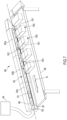
- the shrink apparatus 1 comprises an inlet 2 for receiving containers to be processed and an outlet 3 for delivering processed containers.
- a heat treatment zone 4 (see figure 3 ) is defined between the inlet and the outlet: the heat treatment zone 4 is configured to heat shrink the main portion 101 of processed containers.
- the heat treatment zone 4 only receives the main portion 101 of the processed containers 100 and is configured to direct heat basically only onto the containers main portion.
- the heat shrink apparatus 1 comprises a heat protected zone 5 extending adjacent to the heat treatment zone 4 and configured for receiving the terminal portion 102 of each container and for protecting the terminal portion from heat coming from the heat treatment zone 4, such that the terminal portion 102 of each container 100 is not heat shrunk or at most minimally heat shrunk to an extent largely inferior to the heat shrinking applied to the main portion 101.
- the heat shrink apparatus 1 is a capable of selectively heat shrinking only or substantially only the main portion 101 of each processed container.
- the heat protected zone 5 is connected to the heat treatment zone 4 via one or more openings 6 (see figure 5 ) extending between the heat treatment zone 4 and the heat protected zone 5: in this way, each of the processed containers 100 may have the respective main portion 101 travelling in the heat treatment zone 4, the respective intermediate portion 103 crossing the mentioned one or more openings 6, while the terminal portion 102 remains protected by and travels inside the heat protected zone 5.
- the one or more openings 6 may comprise a single longitudinal opening extending along to the entire heat treatment zone and positioned between the heat treatment zone 4 and the heat protected zone 5: the single longitudinal opening may for example be in the form of a longitudinal slit or of a thin and elongated opening configured for receiving at least the intermediate portion of each processed container, such that, during operation of the heat shrink apparatus, the main portion 101 of each processed container 100 is received in the heat treatment zone 4, while the terminal portion 102 of each processed container remains outside the heat treatment zone 4 with the intermediate portion of each container passing through the longitudinal opening 6.
- the apparatus may present a plurality of discrete openings 6 formed along the heat treatment zone and each configured for receiving the intermediate portion 103 of a respective processed container 100, such that, during operation of the heat shrink apparatus, the main portion 101 of each processed container is received in the heat treatment zone 4, while the terminal portion 102 of each processed container remains outside the heat treatment zone with the intermediate portion of each container passing through a respective discrete opening 6.
- the heat treatment zone 4 also comprises a support structure 20 configured for supporting the main portion 101 of each processed container during motion from the inlet 2 to the outlet 3 of the heat shrink apparatus 1.
- the support structure 20 may for example be formed by a plurality of adjacent rollers 21 (for example idle rollers with axis of rotation orthogonal to the direction of movement of the containers in the zone 4) positioned at intervals along the heat treatment zone and displaceable along a closed path, which comprises a top segment extending from said inlet 2 to said outlet 3, by a chain mechanism 22 operative at each end of the rollers 21, as shown in figure 4 .
- the support structure 20 may comprise idle rollers and driven rollers positioned at intervals along the heat treatment zone or all driven rollers.
- the support structure 20 may be contemplated such as a simple sliding plane extending along the heat treatment zone, or a conveyor belt extending along the heat treatment zone and actively driving the main portions of the processed containers.
- driven means such as one or more driven rollers or one or more conveyor belts, these driven means are controlled by the control unit 200 and synchronized with the motion of the pair of belts acting on the intermediate portion of the processed packages (as it will be further explained below).
- the apparatus 1 is configured to keep the heat treatment zone 4 at a shrink temperature sufficiently high to heat shrink the material of the film used to form the containers 100, while at the same time keeping the heat protected zone 5 at a temperature sufficiently below the film shrink temperature: for example in a currently preferred option the apparatus 1 is configured for keeping the heat protected zone at a temperature at least 30° C below said shrink temperature, optionally at a temperature at least 50° below the shrink temperature.
- the heat treatment zone 4 comprises at least one heater 7 which, during operation of the apparatus, is configured to maintain the heat treatment zone at a/the shrink temperature, which is above 130° C, optionally comprised between 130° and 180° C, more optionally in a range of 160° ⁇ 10 °C.
- the temperature range maintained in the heat treatment zone 4 depends upon the material of the film used for the containers 100 and may be set by a user acting on a user interface 201 associated to a control unit 200 operatively connected to and controlling the one or more heaters 7.
- the apparatus and specifically the heat treatment zone comprises a plurality of independently controllable heaters 7 (for example controllable by said control unit 200): in a possible implementation 2 to 5 or even more independently controllable heaters 7 may be used, distributed along longitudinal development of the heat treatment zone 4, as shown in figure 4 , thereby defining a corresponding plurality of independently heat controllable consecutive longitudinal sections 4a of the heat treatment zone 4.
- the heat treatment zone also has one or more temperature sensors 8, distributed along the heat treatment zone: the control unit 200 is communicatively connected with the one or more temperature sensors 8 and with the heater or heaters 7.
- the control unit 200 is configured to:
- control unit 200 is configured to control the heater or heaters 7 based on said one or more temperature signals and on one or more reference values in order to maintain the temperature of the heat treatment zone within a set temperature above 130° C, optionally comprised between 130° and 180° C, more optionally in a range of 160° ⁇ 10 °C.
- each one of the heaters 7 comprises a heating source 7a (for example an electric resistor or a IR heating source or other) and one or more fans 7b configured to blow on the heating source and direct hot hair in the heat treatment zone, for example via appropriate channels leading to nozzles 7c which are distributed on a top portion and on one or more sides of the heat treatment zone 4, as shown in figure 4 , to thereby direct hot air towards the processed containers both from above and from one or more sides.
- a heating source 7a for example an electric resistor or a IR heating source or other
- fans 7b configured to blow on the heating source and direct hot hair in the heat treatment zone, for example via appropriate channels leading to nozzles 7c which are distributed on a top portion and on one or more sides of the heat treatment zone 4, as shown in figure 4 , to thereby direct hot air towards the processed containers both from above and from one or more sides.
- the support structure 20 described above has through apertures or passages 23 at intervals (in case the support surface is formed by rollers this is evident, but also in case the support surface is defined by a conveyor or by a sliding plane a plurality of through apertures may be distributed all along the support surface) for hot air coming from the heater 7, which is conveniently located below the support structure 20, and configured to direct air towards the processed containers also from below the support structure such that hot air may impinge also on the inferior side of the processed containers.
- the heat treatment zone is uniformly a heated and the containers main portions 101 uniformly treated with hot air, thus performing an efficient heat shrinking with the heated air without use of any liquid.
- the apparatus 1 is configured during operation (i.e., while the containers 100 are processed and the main portions thereof heat treated and shrunk in the heat treatment zone 4) to keep the heat protected zone 5 at a temperature below 100° C, in particular below 90° C.
- one or more heat insulators 9 delimit the heat treatment zone 4 and are in particular in the form of one or more heat insulating walls positioned at the periphery of the heat treatment zone.
- the heat insulators 9 include at least one heat insulating wall or diaphragm 10 just interposed between the heat protected zone 5 and the heat treatment zone and delimiting the opening(s) 6. As shown in figure 5 , there may be two adjacent heat insulating walls or diaphragms 10 located at the opening(s) 6 on opposite sides of the same opening(s).
- the heat protected zone 5 of the enclosed example also comprises a cooling structure 11 defining an elongated seat 12 ( figure 5 ), which may for example be in the form of an elongated flat channel, configured for receiving the terminal portions 102 of each processed container: the seat 12 has a proximal side 12a ending at said one or more longitudinal openings 6 in order to receive the containers terminal portions.
- the mentioned heat insulating wall 10 is interposed between the side of the cooling structure 11 proximal to the heat treatment zone 4 and the same heat treatment zone 4, such that on the one side the wall 10 provides an insulating effect and on the other the cooling structure further acts in cooling the received terminal portions 102.
- the cooling structure 11 may be formed by one or more longitudinally extending bodies made in heat conductive material (such as metal, in particular Aluminum) and may be provided with heat dissipating features such as protruding cooling fins.
- the heat protected zone comprises at least one active cooler 13 which, during operation of the apparatus 1, is configured to act on the cooling structure 11 to keep the elongated seat 12 of the heat protected zone at a temperature at least 30° C below said shrink temperature, more optionally at a temperature at least 50° below the shrink temperature.
- the heat protecting structure 5 may have a plurality of coolers, for example from 2 to 5 coolers, distributed along the heat protected zone and independently controllable by the control unit 200.
- Each cooler 13 may be configured to cool at least cooling structure described above and may at this purpose comprises a cooling fan 13a configured to blow cold air towards cooling structure 11 and/or a liquid cooling system having a source of cold liquid (not shown) and an associated cold liquid circuit 13b circulating cold liquid inside or adjacent to cooling structure 11 via appropriate pipes or channels.
- a cooling fan 13a configured to blow cold air towards cooling structure 11 and/or a liquid cooling system having a source of cold liquid (not shown) and an associated cold liquid circuit 13b circulating cold liquid inside or adjacent to cooling structure 11 via appropriate pipes or channels.
- the heat protected zone may further include one or more auxiliary temperature sensors 14 operative at the heat protected zone: in this case the control unit 200 would be communicatively connected with the one or more auxiliary temperature sensors 14 and with the active cooler or coolers 13 and would be configured to:
- the shrink apparatus 1 comprises a tunnel 15 delimiting or containing the heat treatment zone (the tunnel 15 being preferably formed from wall(s) 16 in insulating material) and optionally the heat protected zone 4: as it is visible the longitudinal opening(s) is for example defined at a longitudinal side portion of the tunnel facing the heat protected zone 5.
- the heat protected zone is positioned adjacent the one or more longitudinal openings and may extend on a side of said tunnel. In a currently preferred variant all walls of the tunnel are made from heat insulating material.
- the above described longitudinal opening 6 is for example in the form of a longitudinal slit, in particular of a longitudinal and rectilinear slit, through the wall 10 which extends in the tunnel and extends from the inlet to the outlet of the heat shrink apparatus and which separates the heat treatment zone from the heat protected zone.
- the heat treatment zone and the heat protected zone extend horizontally, nothing excludes the heat shrink apparatus 1 and thus the heat treatment zone 4 and the heat protected zone 5 be inclined or vertical, with the containers thus moving from inlet to outlet along a non-horizontal path.
- a pair of opposed belts 17 having mutually facing rectilinear belt stretches 17a operate in correspondence of said opening(s) 6.
- the opening or openings 6 may be formed on the wall 10 interposed between the heat treatment zone and the heat protected zone and the two belts 17 may be placed immediately adjacent to said opening(s) 6 and said wall 10, or alternatively the openings may directly be defined by the mutually facing belt stretches of the two cooperating and opposed belts 17.
- the two opposed belts are endless belts engaged to respective two or more pulleys 18 at least one of which is a driven pulley.
- Each pair of opposed belts is designed according one the following alternatives:
- the apparatus 1 may include a regulator for adjusting the size, in particular the thickness, of the one or more longitudinal openings 6.
- a further regulator operative on one or both the belts of each pair of opposed belts to adjust the size of the gap or the entity of pressure between mutually facing stretches of the two belts forming each pair of belts.
- Another aspect concerns a process of heat shrinking a selected portion of the described containers 100: in particular, the process uses the apparatus 1 and allows to heat shrink the main portion 101 of each processed container 100 without basically heat shrinking the terminal portion 102 of the same containers or heat shrinking the terminal portion of each container significantly less than the main portion.
- the containers 100 are fed to the apparatus inlet 2, with the main portion 101 of each container received in the heat treatment zone 4 and with the terminal portion 102 of each container received in the heat protected zone 5.
- Motion of the containers is continuous at a given speed (greater than zero and preferably constant). Of course a discontinuous step by step movement is not excluded.
- Motion to the containers may be imparted by the support structure or by driving means operative downstream the apparatus 1.
- the containers are displaced from the inlet 2 to the outlet 3: heating and heat shrinking of the main portion 101 of each container take place while the main portion travels along the heat treatment zone 4 and while the terminal portion 102 of each container travels along the heat protected zone 5.
- Heat shrinking the main portion 101 of each container takes place when the main portion of each container is inside the heat treatment zone 4 of the apparatus 1 and is at least brought above a shrink temperature causing shrink of the film material forming said main portion.
- the terminal portion 102 of each container is maintained outside the heat treatment zone and sufficiently insulated from this latter, such that no heat shrinking (or just a minimal heat shrinking significantly less than that on the main portion) occurs to the terminal portion which is constantly maintained at a temperature below the shrink temperature, optionally at a temperature at least 30° C below said shrink temperature, more optionally at a temperature at least 50° below the shrink temperature.
- the apparatus 1 is controlled such that the heat treatment zone 4 is heated to bring the main portion of each container above 130° C, optionally between 130° and 180° C, while at the same time the heat protected zone maintains the respective terminal portion of each container at a temperature below 100° C, in particular below 90° C.
- the heater or heaters 7 of apparatus 1 are activated and the heat treatment zone 4 is heated with hot air, which is then delivered onto the main portion 101 determining heat shrinking without use of liquid.
- the intermediate portion 103 of each processed container extends through the one or more openings 6 (and if present between the opposite belts 17 of apparatus 1) and the terminal portion 102 positions inside the cooled structure 11 of the heat protected zone 4 described above.
- the heat protected zone may be cooled with cooling liquid and/or cooling air active on the mentioned cooled structure 11 hosting the terminal portions of the containers.
- the main portion contracts and contacts the surface of the product forming a plastic skin on and around the same product and causing air to escape from the inside of the main portion via the intermediate portion 103 and out of the container 100 via aperture 102a.
- the one or more openings 6 are sized such that, during heating of the main portion 101 of each container, initially air inside the main portion expands the main portion (due to the resistance to air passage offered by the intermediate and terminal portions of each container positioned in the opening 6 and optionally between belts 17); then heat shrinking generates contracting forces on the film of the main portions 101 causing each main portion to contract and contact the surface of the product forming a plastic skin on and around the same product, and also causing air to escape from the inside of the main portion via the intermediate portion and out of the container.
- no vacuum is applied at the terminal portion 102 or at the aperture 102a of each container: in other words gas is evacuated from the main portion 101 of each container solely by effect of heat shrinking of the same main portion pushing gas out of said aperture 102 and with no need of a positive action by a vacuum chamber, or similar vacuum apparatus, operative on the aperture 102a of the terminal portions 102.
- the intermediate portion 103 of each container is also captured between the mutually opposed rectilinear stretches 17a the described pair of belts 17, which contact the surface of the intermediate portion of each container and compress it without however causing a total occlusion to gas exiting from the main portion of each container via said intermediate portion.
- the belts may in practice aid in precisely controlling the position of the terminal portions of the processed containers also aiding in driving the containers from the inlet to the outlet, while leaving escape channels 19a open to gas evacuation.
- the process and the apparatus 1 above described thus allow an efficient gas evacuation from the main portion of the processed packages and also a stretching of the film at the main portion with a consequent positive aesthetical effect as the main portion of the package copies as a skin the contained product an yet remains free or substantially free of wrinkles. Furthermore, as the terminal portion is not heat treated there is no risk of sticking of the internal surfaces of the terminal portion and thus gas can reliably evacuate during the entire process with no need of applying vacuum from the outside of the package.
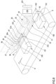
- FIG. 8 Another aspect of the invention concerns a heat shrink device 30, shown in detail in figure 8 , for processing the above described containers 100 and adapted for heat treatment and specifically for heat shrinking the terminal portions 102 not occupied by product of said containers 100.
- the device 30 may be for example used together with the apparatus 1 described above and specifically may operate on containers which have already been processed by apparatus 1 to heat shrink the terminal portion 102 of the containers, which as above discussed is not heat treated by the apparatus 1.
- the device 30 comprises a pair of opposed shrink belts 31: each shrink belt 31 has an operative stretch 31a facing a corresponding operative stretch of the opposite shrink belt and forming a gap 32. More precisely, the operative stretches 31a have respective external surfaces, which are opposite to each other and define therebetween the mentioned gap 32. The gap extends all along the mutually facing stretches 31a of the belts and is configured for receiving the terminal portion 102 of each container 100 to be processed.
- a belt heater 33 is associated to at least one of said shrink belts.
- a belt heater 33 is associated to each shrink belt 31.
- Each belt heater 33 s configured for bringing the external surface of the operative stretch 31a of the respective belt 31 at least at a shrink temperature sufficient to cause heat shrinking of the film forming the terminal portion of the processed packages.
- each belt heater 33 is configured for bringing the external surface of the operative stretch of the respective belt at a shrink temperature comprised between 130° and 180°C, such that the terminal portion of each processed container passing through said gap is heat shrunk.
- the heat shrink device 30 further comprises a flattening body 34 associated to one or both shrink belts 31 and configured for maintaining flat at least a portion of said external surfaces of the flat stretches.
- the flattening body 34 may be a body in a conductive material, such as a metal and in particular Aluminum, and is positioned downstream the belt heater 33 associated to the same belt 31, with respect to a direction of movement A imparted by the opposed shrink belts to the processed containers.
- Each flattening body 34 has a flat active surface 34a acting on the respective operative stretch 31a of the corresponding shrink belt 31.
- each one of operative stretches 31a is a rectilinear stretch having a respective external surface which is a flat surface and the gap 32 is, in an option, a constant thickness planar gap: the thickness of the gap may be comprised between 0.1 mm and 2.0 mm, optionally between 0.3 mm and 1.0 mm.
- each shrink belt 31 is an endless belt engaged between at least a respective driving pulley 35 and a respective driven pulley 36: each shrink belt 31 is particularly large in width and specifically the width of each shrink belt is comprised between 20 mm and 60 mm, optionally between 30 mm and 50 mm thereby being able to efficiently heat treat terminal portions of relatively big size.
- the heater 33 associated to each shrink belt is housed inside a loop defined by each respective endless shrink belt 31 and configured for heating by direct contact an inside surface of the respective shrink belt and in particular the inside surface of the operative stretch of the respective shrink belt.
- the flattening body 34 associated to each shrink belt is also housed inside a loop defined by each respective endless belt and configured for directly contacting an inside surface of the respective shrink belt.
- the heat shrink device 30 may also comprise a pair of rollers 37 operative downstream the opposed shrink belts 31 with respect to a direction of movement A imparted by the opposed shrink belts to the processed containers 100: the pair of rollers 37 cooperate to define a nip therebetween for receiving the terminal portion 102 of each processed container and for further squeezing the terminal portions of the processed containers reducing as possible any wrinkles.
- the device 30 may include a sealer 38 configured to form a heat sealing band on the terminal portion of each processed bag thereby hermetically sealing each processed container.
- the sealer 38 may be separate from the described components (belts and rollers) or it may be associated to one or rollers, for example in the form of a heated circumferential feature on the external surface of one or both the rollers 37 (see figure 8 ), or to one of the opposed belts optionally in the form of a heated feature on the external surface of one or both the opposed shrink belts.
- the heated feature on the roller or on the shrink belt may be independently heated to reach a temperature adequate to cause formation of a seal band across the terminal portions of the processed packages.
- the above components of the device 30, namely the belts and related driving pulleys, the heaters, and the rollers, as well as the sealer, if present, may be controlled by control unit 200 or by a dedicated controller of device 30.
- a further aspect of the invention concerns a process of heat shrinking a selected portion of above described containers and specifically the terminal portion 102 not occupied by product.
- the process of heat treatment of the terminal portion 102 of said containers may be executed using the heat shrink device 30 described above and comprises heat shrinking the terminal portion 102 of each container: in particular, during heat shrinking of the terminal portion 102 of the processed containers 100, the main portion 101 of the same containers is not heat shrunk or in any case is heat shrunk significantly less than the terminal portion.
- the terminal portion 102 of each processed container is inserted into said gap 32 defined by said shrink belts 31 of the heat shrink device 30 ( figure 8 ) and heat shrunk while travelling within said gap.
- each respective belt heater 33 associated to each shrink belt is operated for bringing said external surfaces of both the operative stretches 31a at least at a shrink temperature comprised between 130° and 180°C, such that the terminal portion 102 of each processed container passing through said gap 32 is also brought to said shrink temperature and thus heat shrunk.
- the terminal portion 102 of each container, while travelling through the gap 32 between the two shrink belts of device 30 is put in contact with and flattened by the external surfaces of the flat stretches 31a, also thanks to the action on the belts of flattening bodies 34.
- the process may also provide a step of squeezing the terminal portion of each processed container between the above described pair of rollers 37 operative downstream the opposed shrink belts 31.
- the process may also provide for forming with said shrink belts a heat sealing band on the terminal portion of each processed container thereby hermetically sealing each processed container.
- the process may provide for forming with said pair of rollers a heat sealing band or a further heat sealing band on the terminal portion of each processed bag thereby hermetically sealing each processed container.
- the main portion of each container is maintained at a temperature below the shrink temperature, optionally at a temperature at least 30° C below said shrink temperature, more optionally at a temperature at least 50° below the shrink temperature.
- the terminal portion of each container may be brought at a temperature above 130° C, optionally between 130° and 180° C, while the respective main portion is maintained at a temperature below 100° C, in particular below 90° C.
- the process may provide (typically at the beginning of the process) for a step of adjusting the size of said gap 32 before processing said containers in order to adapt the gap to the thickness of the film of the containers being processed.
- Packaging line 50 for making closed and heat shrunk packages.
- each packaging line 50 is destined to form a closed and heat shrunk package 110 starting from a heat shrinkable film 51.
- the formed packages 110 may be bags or pouches and in particular may be made from heat shrinkable plastic film showing a free shrinking value at 120 °C (value measured in accordance with ASTM D2732, in oil) in the range from 2% to 80% in both longitudinal and transverse directions, optionally in the range from 5% to 60% in both longitudinal and transverse directions, more optionally in the range from 10% to 40% in both longitudinal and transverse directions.
- the packaging line 50 of figures 1 and 2 comprise a loader 52 of the containers 100: as already discussed, the containers have a main portion 101 where a product P is housed, a terminal portion 102 having at least one aperture allowing gas evacuation from the container, and an intermediate portion 103 connecting the main portion and the terminal portion.
- the line 50 comprises the heat shrink apparatus 30 described above positioned immediately downstream the loader 52; the loader is configured to supply said containers 100 to the heat shrink apparatus 30, which is configured to heat shrink the main portion 101 of each container, as explained above.
- the loader 52 is configured to supply said containers 100 to the heat shrink apparatus either in form of interconnected containers (as shown in figures 1 and 2 ) or in form of a sequence of separated containers.
- the loader 52 of the line of figures 1 and 2 comprises a conveyor 53 configured for advancing products P to be packaged along an operating path, and a film supply 54 configured for supplying heat shrinkable plastic film 51 along the operating path and for positioning the film 51 around the products P forming an almost tubular structure 55 housing the products P to be packaged.
- the almost tubular structure 55 may be substantially C or U or V shaped in cross section and in any case forms a longitudinal aperture 55a delimited by opposite longitudinal borders of the film 51.
- film 51 may supplied in the form of a flat film from a film supply 54 comprising a feed roll 54a.
- the flat film 51 is bent on itself by a film former or bending device 56 to confer to the film the desired almost tubular shape.
- the film be directly supplied in the almost tubular form from an extruder or from other film supplying device or that the film is supplied in tubular form and then opened along a longitudinal line to form an almost tubular film structure.
- the loader 52 also includes a transverse sealer 57 configured for forming seal bands 58 transversal to the almost tubular structure 55 forming a plurality of the above described containers 100, each of said containers hosting a respective product at the main portion 101 and having a terminal portion 102 with an aperture, such as with an open end.
- the containers 100 may be severed from each other or, as it is currently preferred, supplied as a chain of interconnected open containers to the heat shrink apparatus 1 described above. Once the heat shrink apparatus has taken care of heat shrinking the main portion 101 of the processed containers 100, the containers exiting from the apparatus 1 may be treated by the heat shrink device 30, which is also part of the lines of figures 1 and 2 .
- the containers 100 with the main portion 101 heat shrunk exiting from apparatus 1 directly reach the heat shrink device 30, which is positioned immediately downstream of the heat shrink apparatus 1 and is configured to receive said containers 100 with heat shrunk main portions 101 and to heat shrink the terminal portions 102 of each processed container.
- the heat shrink device 30 may also be configured to form a heat seal band across the terminal portion of each processed container (for example perpendicular to seal bands 58) to hermetically close said aperture 102a and form closed packages.
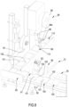
- the packaging line 50 comprises a vacuum station 60 configured for receiving the terminal portions 102 of the processed containers and to suck gas from each container via said aperture 102a.
- the vacuum station 60 of the line of figure 2 is positioned immediately downstream of the heat shrink apparatus 1 and is configured to receive containers 100 with heat shrunk main portions 101 coming from the heat shrink apparatus 1.
- the vacuum station 60 applies to the terminal portions 102 of the processed containers a pressure inferior to the pressure present inside the main portions, thereby sucking gas from each container 100 via said aperture 102a and vacuumizing the containers 100.
- the vacuum station 60 of the line of figure 2 is operatively positioned between the heat shrink apparatus 1 and the heat shrink device 30 and is configured to deliver to the heat shrink device 30 vacuumized containers having heat shrunk and vacuumized main portions.
- the device 30 then threats these containers 100 and heat shrinks the terminal portions 102 thereof as described above.
- the vacuum station 60 may include a own heat sealer 61, for example comprising heat sealing belts or heat sealing wheels or other heat sealing devices, configured to form a heat seal band across the terminal portion of each processed container to hermetically close said aperture and form closed, and vacuumized, packages.
- a own heat sealer 61 for example comprising heat sealing belts or heat sealing wheels or other heat sealing devices, configured to form a heat seal band across the terminal portion of each processed container to hermetically close said aperture and form closed, and vacuumized, packages.
- the vacuum station 60 of the example herein disclosed comprises an elongated vacuum chamber 62 having an elongated opening 63 extending along the vacuum chamber, a vacuum source 64 configured for providing the vacuum chamber 62 with an internal vacuum pressure that is lower than an ambient pressure outside the vacuum chamber, and a conveyor 65 supporting the main portion of the processed containers 100.
- the conveyor 65 may be a conveyor belt or other type of conveyor and is configured for moving the processed containers 100 relative to the vacuum chamber, as shown by arrow B: the containers to be evacuated are positioned so that, during the relative movement of the each container 100 with respect to the vacuum chamber 62, the terminal portion 102 of each container relatively moves within the vacuum chamber 62 and the main portion 101 of each container relatively moves outside the vacuum chamber (and lies on the conveyor 65), with the intermediate portion 103 of each processed container passing through and relatively moving along the elongated opening 63.
- the vacuum station may comprise a first guide belt arranged along a length of the elongated opening 63 and configured with an outer surface contacting the terminal portion of each processed container: the outer surface of the first guide belt 66 is optionally provided with a contoured shape comprising recesses.
- the vacuum station has also a second guide belt 67 arranged along said length of the elongated opening 63, opposed to the first guide belt 66 and configured with a respective outer surface contacting the terminal portion of each processed container: also the outer surface of the first guide belt may optionally be provided with a contoured shape comprising recesses.
- the first and second drive belts 66, 67 are endless belts and their motion is controlled by control unit 200 or by an further controller of the line 50 and is synchronized with the motion of the conveyor 65 supporting the containers main portions.
- the vacuum chamber 62 may include at least a first sub-chamber 62a and a second sub-chamber 62b (a third or more other sub-chambers 62 c may be provided): in this case the vacuum station 60 may be configured to provide the first sub-chamber 62a with a first pressure (in general lower than atmospheric pressure present outside the vacuum station) and to provide the second sub-chamber 62b with a second pressure different from, optionally lower than, the first pressure, to improve as possible flexibility of the vacuum station and ability to extract gas from the processed containers.
- a first pressure in general lower than atmospheric pressure present outside the vacuum station
- second sub-chamber 62b with a second pressure different from, optionally lower than, the first pressure
- a separate sealing station configured for heat sealing the terminal portions of each container (for example by forming one or more seal bands transversal to the terminal portions) and thus form closed packages may be positioned downstream the vacuum station or downstream the device 30 in case the vacuum station and the device 30 are deprived of a own sealer.
- the lines of figures 1 and 2 may also comprise a cutting station 70 (see also figure 9 ) configured for transversely severing the interconnected containers 100 and form a plurality of separated containers: the cutting station 70 is operative either immediately downstream the heat shrink apparatus 1 or immediately downstream the vacuum station 60 (if present) or, in a currently preferred option, downstream the heat shrink device 30 (see figures 1 and 2 ).
- the lines of figures 1 and 2 may also comprise a forming station 80 (schematically represented in figures 1 , 2 and 9 ) configured for forming an easy opening feature: the easy opening feature may be a cut or notch or a weakening line formed at one of the peripheral borders of each processed container 100, for example formed at the terminal portion 102 of each container.
- the forming station 80 is operative either immediately downstream the heat shrink apparatus 1 or immediately downstream the vacuum station 60 (if present) or, in a currently preferred option, downstream the heat shrink device 30, for example before or after or even at the cutting station 70.
- the packaging line 50 may also include a redirecting station 90 configured to orient each processed container 100 such that its terminal portion 102 is oriented towards a direction of motion of the container downstream the same redirecting station: in the examples shown the redirecting station 90 directs the containers transversally with respect to the operating path the containers had upstream the redirecting station 90.
- the redirecting station 90 is operative, in a currently preferred option, downstream the heat shrink device 30 and in particular downstream the cutting station 70 in order to act on containers which are no longer interconnected.
- the packaging line 50 comprises also a heat shrink finisher 91 operative downstream the heat shrink apparatus 1, in particular downstream the heat shrink device 30.
- the heat shrink finisher 91 may for example be located immediately upstream the re-directing station 90 (if present).
- the heat shrink finisher 91 is configured to direct hot air, optionally hot air at a temperature comprised between 130 and 180°C, at least towards the intermediate portion 103 of each processed container to basically heat shrink also the intermediate portion which may have not been properly shrunk at the preceding stations.
- the heat shrink finisher 91 optionally comprises two opposite hot air blowers 92 configured for acting on opposite sides of the intermediate portion of each processed container: the two air blowers are independently controlled, for example by control unit 200, and are able to control bending of the terminal portion of each processed container.
- the lines of figures 1 and 2 may also comprise a labelling station 95 configured for applying at least one label 96 to each processed container: in particular, the labelling station 95 may be adapted to apply a label 96 to the terminal portion of each processed container; the labelling station 95 is operative downstream the heat shrink apparatus 1, in particular downstream the heat shrink device 30 and, if present, downstream the redirecting station 90.
- the labelling station includes a label feed roll 97, guide rollers or other guide means 98 configured for driving and positioning the adhesive label 96 on the portion of interest of each container arriving at the labeling station, and a waste roll 99 for receiving the support layer 96a which carried the applied label 96.
- Packaging process for making closed and heat shrunk packages using packaging line 50.
- a further aspect of the invention concerns a packaging process using the line 50 described above for example the packaging line of figure 1 or the packaging line of figure 2 .
- the process provides for forming or receiving a plurality of containers 100 of the type described above, namely made from heat shrinkable plastic film and having a main portion 101 where a product P is housed, a terminal portion 102 having at least one aperture 102a allowing gas evacuation from the container, and an intermediate portion 103 connecting the main portion and the terminal portion.
- preformed containers 100 of the type described above either interconnected or separated from each other may be supplied directly to the heat shrink apparatus 1.
- the process provides for inline forming the containers 100.
- the forming of the containers may take place at the loader 52 described above and may include:
- the almost tubular structure 55 has a longitudinal aperture 55a, optionally a longitudinal side aperture, and the containers formed from the almost tubular structure are either in the form of interconnected containers or, if a severing sub step takes place, in the form of a sequence of separated containers.
- the process then provides for executing on the containers a process of heat shrinking the main portion 101 of the containers using the heat shrink apparatus 1 and subsequently executing a process of heat shrinking the terminal portions 102 of the processed containers using the heat shrink device 30.
- the process forms a heat seal band across the terminal portion of each processed container to hermetically close said aperture and form closed packages 110.
- closure of the containers with a sealer forming a heat seal band may also take place before heat shrinking the terminal portions or after vacuumization at vacuum station 60 when this latter is present (variant of figure 2 ).
- the containers exiting from apparatus 1 and thus having their main portions 101 heat shrunk are treated at the vacuum station 60 described above where withdrawing of gas from each container 100 via said aperture 102a is obtained by applying a vacuum from outside each terminal portion 102.
- the steps of receiving the containers at the vacuum station 60 and withdrawing gas preferably take place after said main portion 101 of the containers housing the product P has been heat shrunk and before heat shrinking the terminal portion 102 of containers.
- the vacuum station 60 applies to the terminal portions 102 of the processed containers a pressure inferior to the pressure present inside the main portions, thereby sucking gas from each container via said aperture and forming vacuumized containers having heat shrunk main portions.
- the vacuum station 60 may be of the type described above in connection with the packaging line of figure 2 .
- the vacuum station 60 may comprise a own heat sealer 61 forming a heat seal band across the terminal portion of each processed container to hermetically close said aperture and form closed packages.
- the containers 100 or closed packages 110 exiting from the vacuum station 60 arrive at the shrink device 30 where the terminal portions are heat shrunk. Then, if the containers or closed packages are still interconnected they reach cutting station 70, which transversely severs the interconnected containers and forms a plurality of separated containers. Subsequently or at the same time with cutting or before the cutting, a step of forming an easy opening feature (at forming station 80), optionally a cut or notch or a weakening line, at one of the peripheral borders of each processed container is provided: for example forming the easy opening feature may take place after said main portion of the containers housing the product has been heat shrunk, optionally after also said terminal portion of the containers has been heat shrunk.
- the process implemented by the lines of figures 1 and 2 also comprises a step of redirecting each processed container such that its terminal portion extends forward from the main portion towards a direction of motion of the container: in the examples shown redirecting takes place at redirecting station 90, after said terminal portion 102 of the containers has been heat shrunk and before labelling.
- the process may provide for a heat shrink finishing step, which takes place after said main portion 101 of the containers housing the product has been heat shrunk and after also said terminal portion 102 of the containers has been heat shrunk;
- the heat shrink finishing step (operated at finishing station 91) includes directing hot air, optionally hot air at a temperature comprised between 130 and 180°C, at least towards the intermediate portion of each processed container.
- the heat shrink finishing step may use two opposite hot air blowers 92 acting on opposite sides of the terminal portion of each processed container: the two air blowers are independently controlled and, by piloting the respective hot air jets in a differentiated manner, cause a controlled bending of the terminal portion 102 of each processed container or closed package.
- the process may provide for applying at least one label 96 (at labelling station 95) to each processed container or package, in particular to the terminal portion of each processed closed package; labelling takes place after said terminal portion of the containers has been heat shrunk.
- labelling station 95 for example a gas tightly closed bag
- the above described lines and processes allow to obtain a gas tightly closed package (for example a gas tightly closed bag) with reduced content of gas, improved aesthetic properties due to the substantial absence of wrinkles on the main portion of the package, and with reduced use of film material.
- the line 50 and the related packaging process use both the apparatus 1 and the device 30 it is not excluded to have a line without the apparatus 1 or without the device 30: for example the line of figure 1 may be deprived of one of the apparatus 1 or the device 30, and the line of figure 2 may be deprived of one of the apparatus 1 or the device 30, thus only heat shrinking a portion of the containers.
Landscapes
- Engineering & Computer Science (AREA)
- Mechanical Engineering (AREA)
- Chemical & Material Sciences (AREA)
- Composite Materials (AREA)
- Packages (AREA)
- Auxiliary Devices For And Details Of Packaging Control (AREA)
- Shaping By String And By Release Of Stress In Plastics And The Like (AREA)
Applications Claiming Priority (2)
| Application Number | Priority Date | Filing Date | Title |
|---|---|---|---|
| EP21178437 | 2021-06-09 | ||
| PCT/EP2022/051960 WO2022258230A1 (en) | 2021-06-09 | 2022-01-27 | Heat shrink apparaus and device for packaging, and packaging line and process using said heat shrink apparatus and device |
Publications (2)
| Publication Number | Publication Date |
|---|---|
| EP4351986A1 EP4351986A1 (en) | 2024-04-17 |
| EP4351986B1 true EP4351986B1 (en) | 2025-06-18 |
Family
ID=76355345
Family Applications (3)
| Application Number | Title | Priority Date | Filing Date |
|---|---|---|---|
| EP22702693.7A Active EP4351986B1 (en) | 2021-06-09 | 2022-01-27 | Heat shrink apparaus and device for packaging, and packaging line and process using said heat shrink apparatus and device |
| EP22702694.5A Pending EP4351987A1 (en) | 2021-06-09 | 2022-01-27 | Heat shrink apparaus and device for packaging, and packaging line and process using said heat shrink apparatus and device |
| EP22728621.8A Active EP4351988B1 (en) | 2021-06-09 | 2022-05-12 | Package and process of making said package |
Family Applications After (2)
| Application Number | Title | Priority Date | Filing Date |
|---|---|---|---|
| EP22702694.5A Pending EP4351987A1 (en) | 2021-06-09 | 2022-01-27 | Heat shrink apparaus and device for packaging, and packaging line and process using said heat shrink apparatus and device |
| EP22728621.8A Active EP4351988B1 (en) | 2021-06-09 | 2022-05-12 | Package and process of making said package |
Country Status (6)
| Country | Link |
|---|---|
| US (3) | US12409995B2 (pl) |
| EP (3) | EP4351986B1 (pl) |
| CN (3) | CN117480098A (pl) |
| ES (2) | ES3036651T3 (pl) |
| PL (2) | PL4351986T3 (pl) |
| WO (3) | WO2022258231A1 (pl) |
Family Cites Families (67)
| Publication number | Priority date | Publication date | Assignee | Title |
|---|---|---|---|---|
| US2622986A (en) * | 1948-08-20 | 1952-12-23 | Wingfoot Corp | Coffee cream package |
| US2851212A (en) * | 1956-01-03 | 1958-09-09 | Delphin J Parmer | Opening device for bags |
| US3011295A (en) * | 1960-06-09 | 1961-12-05 | Coopers Inc | Packaging machine |
| US3087610A (en) * | 1960-12-27 | 1963-04-30 | Grace W R & Co | Plastic multiple pack carrier |
| GB934389A (en) | 1961-01-26 | 1963-08-21 | Union Carbide Corp | Improvements in and relating to packaging articles |
| US3156812A (en) * | 1962-02-14 | 1964-11-10 | Formatron Inc | Oven for shrinking wrappers |
| US3312811A (en) * | 1964-02-04 | 1967-04-04 | Shanklin Frank Garrett | Shrink tunnel |
| GB1133947A (en) * | 1965-04-30 | 1968-11-20 | Hassia Verpackung Ag | Improvements in or relating to packaging containers and methods and apparatus for production thereof |
| US3378988A (en) * | 1966-05-20 | 1968-04-23 | Robert B. Mcclosky | Apparatus for making sealed packages |
| US3430358A (en) * | 1967-01-30 | 1969-03-04 | Doughboy Ind Inc | Shrink tunnel with conveyer and air directing means |
| US3424306A (en) * | 1968-01-15 | 1969-01-28 | Union Carbide Corp | Package and method of producing same |
| US3552088A (en) * | 1968-07-18 | 1971-01-05 | Nishimura Seisakusho Co | Method of and apparatus for packing articles |
| GB1382842A (en) * | 1972-03-16 | 1975-02-05 | Iwema Forpacknings Ab | Package with handle and a method and a machine for the manufacture of said package |
| US3863837A (en) * | 1972-08-17 | 1975-02-04 | Gilbreth Co | Cardless head board merchandising package |
| US3921805A (en) * | 1972-10-10 | 1975-11-25 | Newton L Compere | Rupturable blister pill package with safety backing |
| US4016026A (en) * | 1975-02-24 | 1977-04-05 | Domain Industries, Inc. | Segmented heater for band sealers |
| US4219988A (en) * | 1977-10-11 | 1980-09-02 | Shanklin Corporation | Automatic high-speed wrapping machine |
| US4204379A (en) * | 1978-09-05 | 1980-05-27 | W. R. Grace & Co. | Closed circuit shrink tunnel |
| US4457122A (en) * | 1981-08-21 | 1984-07-03 | W. R. Grace & Co., Cryovac Div. | Vacuum packaging goods in heat shrinkable plastic bags using flexible diaphragms |
| US4580393A (en) * | 1984-04-11 | 1986-04-08 | Furukawa Mfg. Co., Ltd. | Packing apparatus |
| US4958735A (en) * | 1985-06-28 | 1990-09-25 | W. R. Grace & Co.-Conn. | Easy open, hemetically sealed, display package made from heat shrinkable film |
| US4597247A (en) * | 1985-10-15 | 1986-07-01 | The Mead Corporation | Method and apparatus for applying controlled heat to a group of articles disposed within a shrink film wrapper |
| US5169696A (en) * | 1988-12-05 | 1992-12-08 | Du Pont Canada Inc. | Film laminate with easy TD tear |
| US4896770A (en) * | 1989-03-16 | 1990-01-30 | Duracell Inc. | Battery display package |
| DE3924871A1 (de) * | 1989-07-27 | 1991-02-07 | Dieter Kicherer | Verfahren zum schrumpfen von folien sowie schrumpftunnel insbesondere zur durchfuehrung des verfahrens |
| GB2246110B (en) * | 1990-12-07 | 1995-02-15 | Balair Systems Ltd | Method and apparatus for the packaging of products |
| US5060803A (en) * | 1991-01-17 | 1991-10-29 | Beer Jeffrey S | Gussetted flexible package with tear notch to form pour spout |
| US5390477A (en) * | 1991-11-19 | 1995-02-21 | Mcneilab, Inc. | System for applying a heat shrinkable sleeve to a container |
| US5546677A (en) * | 1995-03-28 | 1996-08-20 | Ossid Corporation | Apparatus and method for shrinking film wrapped around a product |
| IT1282672B1 (it) | 1996-02-23 | 1998-03-31 | Grace W R & Co | Pellicole di materiale termoplastico con proprieta' barriera ai gas |
| AU735827B2 (en) | 1996-04-12 | 2001-07-19 | Cryovac, Inc. | Heat sealable film |
| JP3810035B2 (ja) * | 1997-09-08 | 2006-08-16 | 日本精機株式会社 | 易開封性包装袋およびその製造装置 |
| US6299984B1 (en) | 1998-09-14 | 2001-10-09 | Cryovac, Inc. | Heat-shrinkable multilayer thermoplastic film |
| AU765233B2 (en) | 1998-12-18 | 2003-09-11 | Cryovac, Inc. | Highly bi-axially oriented, heat-shrinkable, thermoplastic, multi-layer film and process for the manufacture thereof |
| DE19920057A1 (de) * | 1999-05-03 | 2000-11-09 | Kallfass Gmbh | Verfahren und Vorrichtung zur Verpackung von Gegenständen in Schrumpffolie |
| US20020073661A1 (en) * | 2000-11-03 | 2002-06-20 | Charles Beseler Company | Shrink-wrap packaging system |
| US6962033B2 (en) * | 2000-12-28 | 2005-11-08 | Belco Packaging Systems, Inc. | Automatic high speed wrapping machine |
| US20030223653A1 (en) * | 2002-05-28 | 2003-12-04 | Knoerzer Anthony Robert | Package with pocket and method for making the same |
| US7033077B2 (en) * | 2002-07-16 | 2006-04-25 | Peter Taylor | Sealable bags made of plastics or other materials and method of making plastic sheeting for manufacturing sealable bags |
| US7374045B2 (en) * | 2003-03-26 | 2008-05-20 | Diliberto Samuel L | Disaster pack and method for making the same |
| US7155876B2 (en) * | 2003-05-23 | 2007-01-02 | Douglas Machine, Inc. | Heat tunnel for film shrinking |
| US7823366B2 (en) * | 2003-10-07 | 2010-11-02 | Douglas Machine, Inc. | Apparatus and method for selective processing of materials with radiant energy |
| US8562216B2 (en) * | 2004-04-13 | 2013-10-22 | Pac Worldwide Corporation | Tear away opening for multi-layer plastic pack |
| JP2006062739A (ja) * | 2004-08-30 | 2006-03-09 | Yahata Neji:Kk | 収納袋 |
| US20060107622A1 (en) * | 2004-11-22 | 2006-05-25 | Shrink Packaging Systems Corp. | Film side sealing apparatus with closed-loop temperature control of a heater |
| US20090017239A1 (en) * | 2006-01-31 | 2009-01-15 | Felice Ursino | Hermetically Sealable, Easy-Opeanable, Flexible Container of Heat-Shrinklable Thermoplastic Material |
| US7857135B2 (en) * | 2006-10-12 | 2010-12-28 | Mckee Foods Kingman, Inc. | Flexible composite snack package |
| US7815050B2 (en) * | 2006-10-12 | 2010-10-19 | Mckee Foods Kingman, Inc. | Flexible snack package with finger wiping feature |
| USD567668S1 (en) * | 2007-04-25 | 2008-04-29 | David Lin | Self-venting microwaveable reclosable standup pouch |
| US10202229B2 (en) * | 2007-05-21 | 2019-02-12 | Cryovac, Inc. | Easy opening packaging article made from heat-shrinkable film exhibiting directional tear |
| US8272196B2 (en) * | 2007-08-24 | 2012-09-25 | Lantech.Com, Llc | Side seal assembly with indexing mechanism |
| JP5253516B2 (ja) * | 2008-01-15 | 2013-07-31 | ノバルティス アーゲー | 可剥性袋 |
| ES2548177T3 (es) | 2009-09-14 | 2015-10-14 | Cryovac, Inc. | Película termo-retráctil de barrera frente a gases |
| US9162087B2 (en) * | 2012-06-28 | 2015-10-20 | Zodiac Aerotechnics | Double tear bag for emergency oxygen system |
| ES2581296T7 (es) | 2013-05-21 | 2017-07-26 | Cryovac, Inc. | Película termocontraible de barrera a los gases |
| ES2699448T3 (es) * | 2014-11-05 | 2019-02-11 | Cryovac Inc | Procedimiento y aparato para extracción de gas en embalajes |
| US10906677B2 (en) * | 2015-11-10 | 2021-02-02 | Cryovac, Llc | Apparatus and process for evacuation of packages |
| US12291387B2 (en) * | 2016-12-05 | 2025-05-06 | Handipak Holdings Ltd | Drinks pouch |
| CN207015694U (zh) * | 2017-07-07 | 2018-02-16 | 江苏新航合金科技有限公司 | 一种焊丝热塑封设备 |
| IT201800003352A1 (it) * | 2018-03-07 | 2019-09-07 | Easysnap Tech S R L | Confezione sigillata con apertura a rottura in un angolo |
| US11407537B2 (en) * | 2018-08-08 | 2022-08-09 | Cryovac, Llc | Apparatus and method for vacuum skin packaging of a product and a skin packaged product |
| WO2020094267A1 (en) * | 2018-11-06 | 2020-05-14 | Cryovac, Llc | Composite belt, band sealer and band sealing method |
| US11535440B2 (en) * | 2020-01-22 | 2022-12-27 | Sonoco Development, Inc. | Magnetic reseal |
| KR20230002719A (ko) * | 2020-04-21 | 2023-01-05 | 필립모리스 프로덕츠 에스.에이. | 밀봉된 구획부를 갖는 용기 |
| EP4304948B1 (en) * | 2021-03-10 | 2024-07-03 | Amcor Flexibles North America, Inc. | Recyclable bag |
| US11660385B1 (en) * | 2022-05-31 | 2023-05-30 | Becton, Dickinson And Company | Package for medical device |
| EP4292828B1 (en) * | 2022-06-14 | 2025-03-12 | Sihl GmbH | Unprinted inkjet-printable fillable pouches and methods for producing and printing said pouches |
-
2022
- 2022-01-27 US US18/568,062 patent/US12409995B2/en active Active
- 2022-01-27 CN CN202280039842.0A patent/CN117480098A/zh active Pending
- 2022-01-27 WO PCT/EP2022/051961 patent/WO2022258231A1/en not_active Ceased
- 2022-01-27 EP EP22702693.7A patent/EP4351986B1/en active Active
- 2022-01-27 US US18/568,026 patent/US12325571B2/en active Active
- 2022-01-27 EP EP22702694.5A patent/EP4351987A1/en active Pending
- 2022-01-27 WO PCT/EP2022/051960 patent/WO2022258230A1/en not_active Ceased
- 2022-01-27 PL PL22702693.7T patent/PL4351986T3/pl unknown
- 2022-01-27 ES ES22702693T patent/ES3036651T3/es active Active
- 2022-01-27 CN CN202280039808.3A patent/CN117412907A/zh active Pending
- 2022-05-12 WO PCT/EP2022/062967 patent/WO2022258305A1/en not_active Ceased
- 2022-05-12 CN CN202280039810.0A patent/CN117440917A/zh active Pending
- 2022-05-12 US US18/568,327 patent/US20240270469A1/en active Pending
- 2022-05-12 PL PL22728621.8T patent/PL4351988T3/pl unknown
- 2022-05-12 ES ES22728621T patent/ES3041410T3/es active Active
- 2022-05-12 EP EP22728621.8A patent/EP4351988B1/en active Active
Also Published As
| Publication number | Publication date |
|---|---|
| CN117412907A (zh) | 2024-01-16 |
| US20240270429A1 (en) | 2024-08-15 |
| US20240270428A1 (en) | 2024-08-15 |
| WO2022258305A1 (en) | 2022-12-15 |
| US12409995B2 (en) | 2025-09-09 |
| EP4351986A1 (en) | 2024-04-17 |
| EP4351988B1 (en) | 2025-07-30 |
| CN117440917A (zh) | 2024-01-23 |
| EP4351988A1 (en) | 2024-04-17 |
| WO2022258230A1 (en) | 2022-12-15 |
| US12325571B2 (en) | 2025-06-10 |
| PL4351988T3 (pl) | 2025-11-24 |
| US20240270469A1 (en) | 2024-08-15 |
| CN117480098A (zh) | 2024-01-30 |
| PL4351986T3 (pl) | 2025-08-18 |
| EP4351987A1 (en) | 2024-04-17 |
| ES3041410T3 (en) | 2025-11-12 |
| WO2022258231A1 (en) | 2022-12-15 |
| ES3036651T3 (en) | 2025-09-23 |
Similar Documents
| Publication | Publication Date | Title |
|---|---|---|
| US5062217A (en) | Selective sequential shrink apparatus and process | |
| US3542570A (en) | Process of manufacturing individually wrapped slices of extrudable products | |
| EP3594137B1 (en) | Apparatus and process for evacuation of packages | |
| EP2722280A1 (en) | Packaging process and packaging apparatus | |
| HRP20050054A2 (en) | Packaging method and device | |
| US3542568A (en) | Process for packaging and sterilization of bread | |
| US20220040955A1 (en) | Composite belt, band sealer and band sealing method | |
| EP4351986B1 (en) | Heat shrink apparaus and device for packaging, and packaging line and process using said heat shrink apparatus and device | |
| EP3427757A2 (en) | A sterilization apparatus for sterilizing a web of packaging material and a sterilization method | |
| WO2011090373A1 (en) | Method and device for packaging a product, and a packaged product | |
| US3171238A (en) | Sealing method | |
| EP2762413A1 (en) | Method and device for packaging a product, and a packaged product | |
| SE433837B (sv) | Sett och anordning for forpackning i steril miljo med anvendning av ett band av termoplastiskt material som er bade sterilt och vid formningstemperatur | |
| JP7228244B2 (ja) | 製袋装置及びそれを用いた包装機 | |
| JP2000281008A (ja) | Ptp包装装置 |
Legal Events
| Date | Code | Title | Description |
|---|---|---|---|
| STAA | Information on the status of an ep patent application or granted ep patent |
Free format text: STATUS: UNKNOWN |
|
| STAA | Information on the status of an ep patent application or granted ep patent |
Free format text: STATUS: THE INTERNATIONAL PUBLICATION HAS BEEN MADE |
|
| PUAI | Public reference made under article 153(3) epc to a published international application that has entered the european phase |
Free format text: ORIGINAL CODE: 0009012 |
|
| STAA | Information on the status of an ep patent application or granted ep patent |
Free format text: STATUS: REQUEST FOR EXAMINATION WAS MADE |
|
| 17P | Request for examination filed |
Effective date: 20231212 |
|
| AK | Designated contracting states |
Kind code of ref document: A1 Designated state(s): AL AT BE BG CH CY CZ DE DK EE ES FI FR GB GR HR HU IE IS IT LI LT LU LV MC MK MT NL NO PL PT RO RS SE SI SK SM TR |
|
| DAV | Request for validation of the european patent (deleted) | ||
| DAX | Request for extension of the european patent (deleted) | ||
| REG | Reference to a national code |
Ref country code: DE Ref legal event code: R079 Free format text: PREVIOUS MAIN CLASS: B65D0075000000 Ipc: B65B0007060000 Ref country code: DE Ref legal event code: R079 Ref document number: 602022016077 Country of ref document: DE Free format text: PREVIOUS MAIN CLASS: B65D0075000000 Ipc: B65B0007060000 |
|
| GRAP | Despatch of communication of intention to grant a patent |
Free format text: ORIGINAL CODE: EPIDOSNIGR1 |
|
| STAA | Information on the status of an ep patent application or granted ep patent |
Free format text: STATUS: GRANT OF PATENT IS INTENDED |
|
| RIC1 | Information provided on ipc code assigned before grant |
Ipc: B65B 51/18 20060101ALI20250109BHEP Ipc: B65D 75/58 20060101ALI20250109BHEP Ipc: B65B 53/02 20060101ALI20250109BHEP Ipc: B29C 65/00 20060101ALI20250109BHEP Ipc: B65B 51/00 20060101ALI20250109BHEP Ipc: B65D 75/00 20060101ALI20250109BHEP Ipc: B65B 7/06 20060101AFI20250109BHEP |
|
| INTG | Intention to grant announced |
Effective date: 20250206 |
|
| GRAS | Grant fee paid |
Free format text: ORIGINAL CODE: EPIDOSNIGR3 |
|
| GRAA | (expected) grant |
Free format text: ORIGINAL CODE: 0009210 |
|
| STAA | Information on the status of an ep patent application or granted ep patent |
Free format text: STATUS: THE PATENT HAS BEEN GRANTED |
|
| P01 | Opt-out of the competence of the unified patent court (upc) registered |
Free format text: CASE NUMBER: APP_18435/2025 Effective date: 20250416 |
|
| AK | Designated contracting states |
Kind code of ref document: B1 Designated state(s): AL AT BE BG CH CY CZ DE DK EE ES FI FR GB GR HR HU IE IS IT LI LT LU LV MC MK MT NL NO PL PT RO RS SE SI SK SM TR |
|
| REG | Reference to a national code |
Ref country code: GB Ref legal event code: FG4D |
|
| REG | Reference to a national code |
Ref country code: CH Ref legal event code: EP |
|
| REG | Reference to a national code |
Ref country code: DE Ref legal event code: R096 Ref document number: 602022016077 Country of ref document: DE |
|
| REG | Reference to a national code |
Ref country code: CH Ref legal event code: EP |
|
| REG | Reference to a national code |
Ref country code: IE Ref legal event code: FG4D |
|
| REG | Reference to a national code |
Ref country code: NL Ref legal event code: FP |
|
| REG | Reference to a national code |
Ref country code: ES Ref legal event code: FG2A Ref document number: 3036651 Country of ref document: ES Kind code of ref document: T3 Effective date: 20250923 |
|
| PG25 | Lapsed in a contracting state [announced via postgrant information from national office to epo] |
Ref country code: FI Free format text: LAPSE BECAUSE OF FAILURE TO SUBMIT A TRANSLATION OF THE DESCRIPTION OR TO PAY THE FEE WITHIN THE PRESCRIBED TIME-LIMIT Effective date: 20250618 |
|
| REG | Reference to a national code |
Ref country code: LT Ref legal event code: MG9D |
|
| PG25 | Lapsed in a contracting state [announced via postgrant information from national office to epo] |
Ref country code: NO Free format text: LAPSE BECAUSE OF FAILURE TO SUBMIT A TRANSLATION OF THE DESCRIPTION OR TO PAY THE FEE WITHIN THE PRESCRIBED TIME-LIMIT Effective date: 20250918 Ref country code: GR Free format text: LAPSE BECAUSE OF FAILURE TO SUBMIT A TRANSLATION OF THE DESCRIPTION OR TO PAY THE FEE WITHIN THE PRESCRIBED TIME-LIMIT Effective date: 20250919 |
|
| PG25 | Lapsed in a contracting state [announced via postgrant information from national office to epo] |
Ref country code: BG Free format text: LAPSE BECAUSE OF FAILURE TO SUBMIT A TRANSLATION OF THE DESCRIPTION OR TO PAY THE FEE WITHIN THE PRESCRIBED TIME-LIMIT Effective date: 20250618 |
|
| PG25 | Lapsed in a contracting state [announced via postgrant information from national office to epo] |
Ref country code: HR Free format text: LAPSE BECAUSE OF FAILURE TO SUBMIT A TRANSLATION OF THE DESCRIPTION OR TO PAY THE FEE WITHIN THE PRESCRIBED TIME-LIMIT Effective date: 20250618 |
|
| PG25 | Lapsed in a contracting state [announced via postgrant information from national office to epo] |
Ref country code: RS Free format text: LAPSE BECAUSE OF FAILURE TO SUBMIT A TRANSLATION OF THE DESCRIPTION OR TO PAY THE FEE WITHIN THE PRESCRIBED TIME-LIMIT Effective date: 20250918 |
|
| PG25 | Lapsed in a contracting state [announced via postgrant information from national office to epo] |
Ref country code: LV Free format text: LAPSE BECAUSE OF FAILURE TO SUBMIT A TRANSLATION OF THE DESCRIPTION OR TO PAY THE FEE WITHIN THE PRESCRIBED TIME-LIMIT Effective date: 20250618 |
|
| PG25 | Lapsed in a contracting state [announced via postgrant information from national office to epo] |
Ref country code: PT Free format text: LAPSE BECAUSE OF FAILURE TO SUBMIT A TRANSLATION OF THE DESCRIPTION OR TO PAY THE FEE WITHIN THE PRESCRIBED TIME-LIMIT Effective date: 20251020 |
|
| REG | Reference to a national code |
Ref country code: AT Ref legal event code: MK05 Ref document number: 1804005 Country of ref document: AT Kind code of ref document: T Effective date: 20250618 |