EP4350319A1 - Bench test device and bench test method - Google Patents
Bench test device and bench test method Download PDFInfo
- Publication number
- EP4350319A1 EP4350319A1 EP22815987.7A EP22815987A EP4350319A1 EP 4350319 A1 EP4350319 A1 EP 4350319A1 EP 22815987 A EP22815987 A EP 22815987A EP 4350319 A1 EP4350319 A1 EP 4350319A1
- Authority
- EP
- European Patent Office
- Prior art keywords
- wheel
- steering
- bench
- test device
- rotating body
- Prior art date
- Legal status (The legal status is an assumption and is not a legal conclusion. Google has not performed a legal analysis and makes no representation as to the accuracy of the status listed.)
- Pending
Links
- 238000012360 testing method Methods 0.000 title claims abstract description 195
- 238000010998 test method Methods 0.000 title claims description 6
- 238000009434 installation Methods 0.000 claims abstract description 11
- 238000006243 chemical reaction Methods 0.000 claims description 30
- 238000005096 rolling process Methods 0.000 claims description 11
- 230000000903 blocking effect Effects 0.000 claims description 6
- 230000001419 dependent effect Effects 0.000 claims 1
- 230000006870 function Effects 0.000 description 29
- 238000010586 diagram Methods 0.000 description 14
- 230000002265 prevention Effects 0.000 description 6
- 230000003213 activating effect Effects 0.000 description 4
- NJPPVKZQTLUDBO-UHFFFAOYSA-N novaluron Chemical compound C1=C(Cl)C(OC(F)(F)C(OC(F)(F)F)F)=CC=C1NC(=O)NC(=O)C1=C(F)C=CC=C1F NJPPVKZQTLUDBO-UHFFFAOYSA-N 0.000 description 4
- 230000005540 biological transmission Effects 0.000 description 3
- 230000000694 effects Effects 0.000 description 2
- 238000005259 measurement Methods 0.000 description 2
- 238000000034 method Methods 0.000 description 2
- 239000000725 suspension Substances 0.000 description 2
- 230000002159 abnormal effect Effects 0.000 description 1
- 230000005856 abnormality Effects 0.000 description 1
- 239000000470 constituent Substances 0.000 description 1
- 238000013461 design Methods 0.000 description 1
- 238000006073 displacement reaction Methods 0.000 description 1
- 238000012986 modification Methods 0.000 description 1
- 230000004048 modification Effects 0.000 description 1
- 239000011347 resin Substances 0.000 description 1
- 229920005989 resin Polymers 0.000 description 1
- 238000005201 scrubbing Methods 0.000 description 1
Images


Classifications
-
- G—PHYSICS
- G01—MEASURING; TESTING
- G01M—TESTING STATIC OR DYNAMIC BALANCE OF MACHINES OR STRUCTURES; TESTING OF STRUCTURES OR APPARATUS, NOT OTHERWISE PROVIDED FOR
- G01M17/00—Testing of vehicles
- G01M17/007—Wheeled or endless-tracked vehicles
- G01M17/0072—Wheeled or endless-tracked vehicles the wheels of the vehicle co-operating with rotatable rolls
- G01M17/0074—Details, e.g. roller construction, vehicle restraining devices
Definitions
- the present invention relates to a bench test device and a bench test method for testing a test piece that is a vehicle or a part thereof.
- an ADAS vehicle which has an advanced driving support system (ADAS) or an automatic driving vehicle (hereinafter, an AD vehicle)
- a test of a test piece is performed by, for example, running on a test course simulating an actual road and simulating an external environment of the test piece (i.e., another vehicles, people, or bicycles).
- Patent Literature 1 a vehicle-use free roller device that puts a test piece vehicle into a traveling state has been considered as a bench test device.
- this vehicle-use free roller device only straight traveling is assumed, and a steering wheel of the test piece cannot be steered. That is, this bench test device cannot perform a running test involving steering of an ADAS vehicle or AD vehicle.
- Patent Literature 2 a chassis dynamometer with a steering function has been considered as a bench test device. However, it is necessary to turn rollers on which wheels are placed and an electric dynamometer (dynamometer), and not only does the device become large in scale but cost also increases.
- the present invention has been made in view of the above-described problems, and a main object thereof is to provide an inexpensive bench test device with a steering function for testing a vehicle such as an ADAS vehicle or an AD vehicle.
- a bench test device is a bench test device for testing a test piece that is a vehicle or a part thereof.
- the bench test device includes a rotating body on which a wheel of the test piece is placed, a support bench that rotatably supports the rotating body, and a movement mechanism that moves the support bench on an installation surface using a rotational force of the wheel.
- the support bench that rotatably supports the rotating body on which a steered wheel is placed moves using the rotational force of the wheel, it is possible to provide a bench test device with a steering function for performing a running test involving the steering of a vehicle such as an ADAS vehicle or AD vehicle.
- a vehicle such as an ADAS vehicle or AD vehicle.
- the rotating body is rotatably supported by the support bench and the support bench is moved by the movement mechanism, there is no dynamometer and a low-cost configuration is possible.
- the steered wheel does not rotate about a touchdown point, but steers and rotates about a steering rotation axis (kingpin axis) of the steering wheel, and the rotating body on which the wheel is placed rotates about an extension of the steering rotation axis (kingpin axis) and the touchdown point (virtual touchdown point) of the ground.
- the locus of the rotation axis of the steering wheel and a ground plane of the wheel varies depending on a camber angle, a caster angle, a scrubbing radius, or the like of the suspension, and a steering mechanism, a suspension mechanism, or the like for each vehicle.
- the movement mechanism preferably includes a rolling element provided on the support bench, and the rolling element preferably moves on the installation surface to move the rotating body using the rotational force of the wheel.
- the rotating body is preferably a free roller that rotates by using rotation of the wheel as a power source, or a roller that rotates a tire by applying a rotational force to the rotating body.
- the bench test device preferably further includes a centering mechanism that biases the support bench toward a centering position.
- the centering mechanism include a recess or a protrusion formed on the installation surface, and that the rolling element move along the recess or the protrusion to bias the support bench toward the centering position.
- the centering mechanism include an elastic body or an actuator which biases the support bench toward the centering position.
- the rotating body include a drive wheel-side rotating body on which a drive wheel of the test piece is placed and a driven wheel-side rotating body on which a driven wheel of the test piece is placed, and that the bench test device of the present invention further include an interlocking rotation mechanism that rotates the driven wheel-side rotating body in conjunction with the drive wheel-side rotating body.
- the interlocking rotation mechanism mechanically connect the drive wheel-side rotating body and the driven wheel-side rotating body, and transmit rotation of the drive wheel-side rotating body to the driven wheel-side rotating body.
- the interlocking rotation mechanism include a blocking section that blocks mechanical connection between the drive wheel-side rotating body and the driven wheel-side rotating body.
- the interlocking rotation mechanism include a motor that rotates the driven wheel-side rotating body or the driven wheel, and that the motor rotate the driven wheel-side rotating body in conjunction with the drive wheel-side rotating body or rotate the driven wheel in conjunction with the drive wheel.
- the rotating body be a pair of front wheel-side rotating bodies on which front left and right wheels are respectively placed, that the front left and right wheels be steering wheels of the test piece, and that the bench test device further include a pair of front wheel-side motors that respectively rotate the pair of front wheel-side rotating bodies or respectively rotate the front left and right wheels, and a pair of rear wheel-side motors that respectively rotate a pair of rear wheel-side rotating bodies on which rear left and right wheels of the test piece are respectively placed or respectively rotate the rear left and right wheels.
- the speed of the four wheels of the front left and right wheels and the rear right and left wheels can be individually controlled.
- the bench test device of the present invention further include a turning angle calculator that calculates a turning angle of the front left and right wheels, a turning radius calculator that calculates a turning radius of each wheel by the turning angle, a speed difference calculator that calculates a speed difference of each wheel, and a motor controller that controls the pair of front wheel-side motors and the pair of rear wheel-side motors based on the speed difference of each wheel.
- a bench test device is a bench test device for testing a test piece that is a vehicle or a part thereof.
- the bench test device includes a fixing mechanism that fixes the test piece in a state of floating from a road surface, a pair of front wheel-side motors that rotate respective rotation axes of front left and right wheels of the test piece via a front-side rotating shaft, a pair of rear wheel-side motors that rotate respective rotation axes of rear right and left wheels of the test piece via a rear-side rotating shaft, a turning angle calculator that calculates a turning angle of the front left and right wheels, a turning radius calculator that calculates a turning radius of each wheel based on the turning angle, a speed difference calculator that calculates a speed difference of each of the wheels, and a motor controller that controls the pair of front wheel-side motors and the pair of rear wheel-side motors based on the speed difference of each wheel.
- the bench test device of the present invention preferably includes a steering reaction force input device that inputs a steering reaction force to a steering rack gear of the test piece.
- the bench test device preferably further includes a detector that detects that the steering angle of the steering of the test piece has reached a predetermined steering threshold value, and a control stopping section that stops rotation control of the wheels or steering reaction force control of the steering reaction force input device when the steering angle has reached the steering threshold value.
- the detector preferably includes a contact sensor that comes into contact with a steering rack gear or an interlocking member interlocked with the steering rack gear in a state where the steering angle has reached the steering threshold, and a support member that supports the contact sensor. When the steering angle has exceeded the steering threshold value, the support member slides or falls off according to the steering angle.
- a bench test device is a bench test device for testing a test piece that is a vehicle or a part thereof.
- the bench test device includes a fixing mechanism that fixes the test piece to a road surface, a pair of front wheel-side motors connected to rotation axes of respective front left and right wheels of the test piece via a front-side rotating shaft, a pair of rear wheel-side motors connected to rotation axes of respective rear left and right wheels of the test piece via a rear-side rotating shaft, a turning angle calculator that calculates a turning angle of the front left and right wheels, a turning radius calculator that calculates a turning radius of each wheel based on the turning angle, a speed difference calculator that calculates a speed difference of each wheel, and a motor controller that controls the pair of front wheel-side motors or the pair of rear wheel-side motors based on the speed difference of each wheel.
- the fixing mechanism in order to perform various running tests by statically or dynamically controlling the posture of the test piece, is preferably capable of adjusting the posture of the test piece with respect to a road surface, or is dynamically operable to dynamically change the posture of the test piece with respect to the road surface.
- one aspect of the present invention is also a bench test method for a test piece that is an ADAS vehicle, an AD vehicle, or part thereof using the above bench test device.
- a bench test method for a test piece that is an ADAS vehicle, an AD vehicle, or part thereof using the above bench test device.
- a bench test device with a steering function for testing a vehicle such as an ADAS vehicle or AD vehicle.
- a bench test device 100 of the present embodiment is used to test a test piece W.
- the test piece W is an item such as a vehicle (hereinafter, an ADAS vehicle) with an advanced driving assistance system (ADAS), an automatic driving vehicle (hereinafter, an AD vehicle), or a part thereof.
- a complete ADAS vehicle or AD vehicle is assumed as the test piece W.
- the test piece W may be an incomplete vehicle (a part of an ADAS vehicle or AD vehicle) that is not a complete vehicle as long as it can travel.
- FIG. 1 illustrates an example of a scenario of at bench test method using the bench test device 100 of the present embodiment.
- a method of evaluating the behavior (i.e., lane keeping, overtaking, lane changing, emergency avoidance steering, or the like) of the test piece W is considered.
- the test piece W in a traveling state on the bench test device 100 and the surrounding environment such as the front, rear, side, or the like of the test piece W is changed or a pseudo signal is input to a sensor of the test piece W.
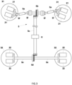
- the bench test device 100 of the present embodiment includes drive wheel-side rotating bodies 21 on which a pair of left and right drive wheels W1 of the test piece W is placed, and driven wheel-side rotating bodies 22 on which a pair of left and right driven wheels (non-drive wheels) W2 of the test piece W is placed.
- the test piece W is fixed by a fixing mechanism FM such that the drive wheels W1 and the driven wheels W2 are not detached from the drive wheel-side rotating bodies 21 and the driven wheel-side rotating bodies 22, respectively.
- the wheels (drive wheels W1 and driven wheels W2) of the present embodiment are in a state where tires are mounted on wheel rims.
- the drive wheel-side rotating bodies 21 are provided for each of the pair of left and right drive wheels W1. Two drive wheel-side rotating bodies 21 are provided for each drive wheel W1, and one drive wheel W1 is mounted on two drive wheel-side rotating bodies 21.
- the drive wheel-side rotating bodies 21 are rotatably supported by a support bench 31 along with the rotation of the drive wheels W1.
- the drive wheel-side rotating bodies 21 are free rollers that freely rotate, and rotate using the rotation of the drive wheels W1 as a power source.
- the driven wheel-side rotating bodies 22 are provided for each of the pair of left and right driven wheels W2. Two driven wheel-side rotating bodies 22 are provided for each driven wheel W2, and one driven wheel W2 is mounted on two driven wheel-side rotating bodies 22.
- the driven wheel-side rotating bodies 22 are rotatably supported by a support bench 32.
- the driven wheel-side rotating bodies 22 are free rollers that freely rotate, and rotate according to a later-described interlocking rotation mechanism 5.
- the bench test device 100 of the present embodiment further includes an interlocking rotation mechanism 5 that rotates the driven wheel-side rotating bodies 22 in conjunction with the drive wheel-side rotating bodies 21 so as to have a constant speed, for example.
- the interlocking rotation mechanism 5 mechanically connects the drive wheel-side rotating bodies 21 and the driven wheel-side rotating bodies 22, and mechanically transmits the rotation of the drive wheel-side rotating bodies 21 to the driven wheel-side rotating bodies 22 at a constant speed.
- the interlocking rotation mechanism 5 includes drive wheel-side rotating shafts 5a that are connected to the drive wheel-side rotating bodies 21 and rotate, a propeller shaft 5c connected to the rotating shafts 5a via a bevel gear 5b, and a driven wheel-side rotating shaft 5e connected to the propeller shaft 5c via a bevel gear 5d and connected to the driven wheel-side rotating bodies 22.
- the drive wheel-side rotating shafts 5a are provided with joints 5f with a floating function for following the steering movement of the drive wheels W1 and transmitting rotation from the drive wheels W1.
- Examples of a joint 5f include a constant speed joint and a universal joint.
- the drive wheel-side rotating shafts 5a use expanding and contracting structures such as spline structures to follow the steering movement of the drive wheels W1. Through such a configuration, the rotational frequency of the drive wheel-side rotating bodies 21 and the rotational frequency of the driven wheel-side rotating bodies 22 are the same.
- the interlocking rotation mechanism 5 may include a blocking section 6 that blocks mechanical connection between the drive wheel-side rotating bodies 21 and the driven wheel-side rotating bodies 22.
- the blocking section 6 is provided on the propeller shaft 53, and uses a clutch mechanism that switches the drive wheel-side rotating bodies 21 and the driven wheel-side rotating bodies 22 between a connected state and a blocked state.
- a four-wheel drive test piece W can be bench-tested by placing the drive wheel-side rotating bodies 21 and the driven wheel-side rotating bodies 22 in a blocked state through the blocking section 6. Switching between a connected state and a disconnected state through the clutch mechanism may be manually performed or may be controlled by an unillustrated controller.
- an interlocking rotation mechanism 5 includes a motor 5g that rotates the driven wheel-side rotating bodies 22, and the motor 5g rotates the driven wheel-side rotating bodies 22 so as to have a constant speed with the drive wheel-side rotating bodies 21.
- the left and right pairs of drive wheel-side rotating bodies 21 are connected by a drive wheel-side link mechanism 5h, and one drive wheel-side rotating body 21 is provided with a rotational speed sensor 5i.
- a motor 5j is connected to the drive wheel-side rotating body 21, and an encoder of the motor 5j is used as the rotational speed sensor 5i.
- the left and right pairs of driven wheel-side rotating bodies 22 are connected by a driven wheel-side link mechanism 5k, and the motor 5g is connected to one of the driven wheel-side rotating bodies 22.
- the motor 5g can be controlled by an unillustrated controller.
- the drive wheel-side link mechanism 5h is provided with joints 5h1 with a floating function for following the steering movement of the drive wheels W1 and transmitting rotation from the drive wheels W1.
- Examples of a joint 5h1 include a constant speed joint and a universal joint.
- the drive wheel-side link mechanism 5h is provided with an expanding and contracting structure such as a spline structure to follow the steering movement of the drive wheel W1. Then, by rotating the motor 5g connected to a driven wheel-side rotating body 22 at a rotational speed (rotational frequency) obtained by the rotational speed sensor 5i, the driven wheel-side rotating bodies 22 rotate at the same speed as the drive wheel-side rotating bodies 21.
- a four-wheel drive test piece W can be bench-tested by allowing the motor 5g connected to a driven wheel-side rotating body 22 to rotate freely.
- a rotational speed sensor 5i (an encoder of a motor 5j may be used) may be provided in each drive wheel-side rotating body 21, and a motor 5g may be connected to each driven wheel-side rotating body 22.
- a configuration in which motors 5g are connected to the driven wheels W2 to directly rotate the driven wheels W2 may be adopted.
- a four-wheel drive test piece W can be bench-tested by allowing the motor 5g connected to a driven wheel-side rotating body 22 to rotate freely.
- the motor 5g can be controlled by an unillustrated controller.
- the bench test device 100 of the present embodiment includes a movement mechanism 4 which moves a support bench that rotatably supports rotating bodies on which steering wheels are placed, using a rotational force generated based on steering of the steered wheels.
- a drive wheel W1 serves as a steering wheel
- the movement mechanism 4 moves the support bench 31 (hereinafter, drive wheel-side support bench 31) that rotatably supports the drive wheel-side rotating bodies 21, using the rotational force generated based on the steering of the drive wheel W1.
- the movement mechanism 4 may use at least a part of the rotational force of the drive wheel W1, and the movement may be assisted by another unillustrated movement assisting mechanism.
- the movement mechanism 4 moves the drive wheel-side support bench 31 according to the steering angle of the steered drive wheel W1, includes rolling elements 41 provided on the support bench 31, and is configured such that the rolling elements 41 move on an installation surface P on which the support bench 31 is installed.
- the movement mechanism 4 enables the drive wheel-side support bench 31 to move with a free locus.
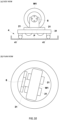
- the movement locus of the drive wheel-side support bench 31 accompanying the steering moves about a virtual touchdown point where a kingpin (a pin serving as a center of steering rotation of the steering wheels) is extended as a rotation center (refer to FIG. 6(b) ).
- the bench test device 100 of the present embodiment further includes a centering mechanism 7 that biases the drive wheel-side support bench 31 toward a centering position.
- the centering position is a position of the drive wheel-side support bench 31 corresponding to the drive wheel W1 in a state where steering is not performed (straight traveling state).
- centering mechanism 7 includes the following.
- the centering mechanism 7 includes a recess 7M or a protrusion 7T formed on the installation surface P, and the rolling elements 41 move along the recess 7M or the protrusion 7T to bias the drive wheel-side support bench 31 toward the centering position.
- the centering mechanism 7 is configured using an elastic body 71 that biases the drive wheel-side support bench 31 toward the centering position. In this configuration, it is conceivable that the drive wheel-side support bench 31 is biased from the outside to the centering position by a plurality of elastic bodies 71.
- the centering mechanism 7 is configured to connect a steering reaction force input device 72 that applies a steering reaction force to the drive wheel-side rotating shaft 5a of the interlocking rotation mechanism 5 to bias the drive wheel-side support bench 31 toward the centering position.
- a steering reaction force input device 72 a device using an actuator such as a cylinder or a motor, a device using an elastic body, or a combination thereof may be considered.
- the drive wheel-side support bench 31 that rotatably supports the drive wheel-side rotating bodies 21 on which the steered wheel (drive wheel W1) is placed move using the rotational force generated based on the steering of the drive wheel W1
- a bench test device 100 with a steering function for performing a running test involving the steering of an ADAS vehicle or AD vehicle.
- the drive wheel-side rotating bodies 21 are rotatably supported by the drive wheel-side support bench 31 and the drive wheel-side support bench 31 is moved by the movement mechanism 4, a dynamometer is not included and a low-cost configuration is possible.
- the drive wheel W1 which is a steering wheel
- the drive wheel-side support bench 31 may be connected to the drive wheel-side support bench 31 via a free hub 8.
- the drive wheel-side support bench 31 can be stably moved with respect to the drive wheel W1 without deviation.
- the bench test device 100 of the above embodiment may include a vehicle height adjustment mechanism 9. As illustrated in FIG. 11(a) , it is conceivable that this vehicle height adjustment mechanism 9 adjusts a vehicle height position by adjusting the interval between two rotating bodies 21 (22) (two rotating bodies 21 (22) sandwiching a wheel W1 or W2) provided corresponding to each wheel W1 (W2). By widening the interval between the two rotating bodies 21 (22) sandwiching the wheel W1 (W2), the vehicle height can be reduced.
- This vehicle height adjustment mechanism 9 can make the vehicle height equivalent to that in a case of traveling on an actual road, and improve the reliability of the vehicle test.
- the bench test device 100 of the above embodiment may further include a tread width adjustment mechanism 10. As illustrated in FIG. 11(b) , this tread width adjustment mechanism 10 adjusts the interval between left and right pairs of drive wheel-side rotating bodies 21 and the interval between left and right pairs of driven wheel-side rotating bodies 22.
- the tread width adjustment mechanism 10 can adjust the tread width to one suitable according to vehicle type.
- the drive wheel-side support bench 31 may be a rotary table.
- the centering mechanism 7 may be configured as a steering reaction force input device 11.
- the steering reaction force input device 11 is connected to a tie rod WT of the test piece W to generate a steering reaction force (centering force) in the tie rod WT.
- a device using an actuator such as a cylinder or a motor, a device using an elastic body, or a combination thereof may be considered as the steering reaction force input device 11.
- the bench test device 100 of the above embodiment has a configuration using rotating bodies 21 and 22 on which wheels W1 and W2 are placed, but the object of the present invention can also be achieved by the following configuration in which the bench test device 100 is connected to wheel rims WH of the wheels W1 and W2.
- the bench test device 100 may be configured such that rotational speed sensors 12 are connected to the wheel rims WH of the drive wheels W1, motors 13 are connected to the wheel rims WH of the driven wheels W2, and the wheel rims WH of the driven wheels W2 are rotated by the motors 13 based on a rotational speed obtained by the rotational speed sensors 12.
- a rotational speed sensor 12 a motor 14 is connected to the wheel rim WH of the drive wheel W1, and the encoder of the motor 14 can be used as the rotational speed sensor 12.
- an expanding and contracting structure 15 with a spline function or the like can be used to follow the steering movement of the drive wheel W 1 and to transmit the rotation from the drive wheel W1.
- the expanding and contracting structure 15 includes a j oint with a floating function such as a constant velocity j oint or a universal joint.
- An expanding and contracting structure 16 such as a spline structure can also be used when a motor 13 is connected to the wheel rim WH of a driven wheel W2. In this manner, the tread width can be adjusted by using the expanding and contracting structures 15 and 16 for connecting the motors 13 and 14.
- steering reaction force input devices 17 may be connected to the expanding and contracting structures 15 connected to the wheel rims WH of the drive wheels W1, which are steering wheels, to generate steering reaction force (centering force).
- a four-wheel drive test piece W can be bench-tested by allowing the motors 13 connected to the wheel rims WH of the driven wheels W2 to rotate freely.
- the wheel rims WH of the drive wheels W1 and the wheel rims WH of the driven wheels W2 may be mechanically connected to mechanically transmit the rotation of the wheel rims WH of the drive wheels W1 to the wheel rims WH of the driven wheels W2.
- a configuration including drive wheel-side rotating shafts 18 connected to the wheel rims WH of the drive wheels W1, driven wheel-side rotating shafts 19 connected to the wheel rims WH of the driven wheels W2, and transmission members 20 such as a belt or a chain bridged between the shafts 18 and 19 is conceivable.
- an expanding and contracting structure 15 with a spline function or the like can be used to follow the steering movement of the drive wheel W1 and to transmit the rotation from the drive wheel W1.
- the expanding and contracting structure 15 includes a joint with a floating function such as a constant velocity joint or a universal joint.
- An expanding and contracting structure such as a spline structure can also be used when a rotating shaft 19 is connected to a wheel rim WH of a driven wheel W2. In this manner, the tread width can be adjusted by using the expanding and contracting structures in the rotating shafts 18 and 19.
- a four-wheel drive test piece W can be bench-tested by releasing the connection between the driven wheel-side rotating shafts 18 and the drive wheel-side rotating shafts 19 though the transmission members 20.
- pairs of front wheel-side rotating bodies 23, pairs of rear wheel-side rotating bodies 24, a pair of front wheel-side motors M1, a pair of rear wheel-side motors M2, and a control device COM are included.
- the front left and right wheels W1, which are steering wheels of the test piece W, are respectively placed on the pairs of front wheel-side rotating bodies 23.
- the rear left and right wheels are respectively placed on the pairs of rear wheel-side rotating bodies 24.
- the front wheel-side motors M1 respectively rotate the pairs of front wheel-side rotating bodies 23.
- the rear wheel-side motors M2 respectively rotate the pairs of rear wheel-side rotating bodies 24.
- the control device COM controls the front wheel-side motors M1 and the rear wheel-side motors M2.
- the pair of front wheel-side motors M1 may be respectively connected to the front left and right wheels W1 via an expanding and contracting structure such as a spline function having a joint with a floating function such as a constant velocity joint or a universal joint
- the pair of rear wheel-side motors M2 may be respectively connected to the rear left and right wheels W2 via a joint with a floating function such as a constant velocity joint or a universal joint.
- control device COM individually controls the speeds of the four wheels of the front left and right wheels W1 and the rear left and right wheels W2.
- control device COM is a dedicated or general-purpose computer including a CPU, memory, an input/output interface, an AD converter, and the like.
- control device COM manifests functions as a turning angle calculator 1a that calculates the turning angle of the front left and right wheels W1, a turning radius calculator 1b that calculates the turning radius of each wheel due to the turning angle, a speed difference calculator 1c that calculates the speed difference of each wheel, and a speed controller 1d that controls the speed of the pair of front wheel-side motors M1 and/or the pair of rear wheel-side motors M2 based on the speed difference of each wheel.
- the turning angle calculator 1a calculates the turning angle of a front wheel rim with respect to a steering wheel steering angle (amount of lateral movement of a steering rack gear) from steering geometry (design value) such as the Ackerman mechanism, for example.
- the turning angle calculator 1a may be replaced with a configuration in which a turning angle in an actual steering wheel steering angle is obtained by a measurement device such as a vehicle basic characteristic measurement device (K&C tester).
- K&C tester vehicle basic characteristic measurement device
- the turning radius of each wheel at a very low speed is as follows.
- the speed controller 1d individually controls each of the pair of front wheel-side motors M1 and the pair of rear wheel-side motors M2 using the wheel speeds obtained as described above so that the front left and right wheels W1 and the rear left and right wheels W2 have the wheel speeds obtained as described above.
- a motor connected to a drive wheel sets the wheel speed of the drive wheel to the value obtained above while applying a load to the drive wheel
- a motor connected to a driven wheel sets the wheel speed of the driven wheel to the value obtained above.
- the bench test device 100 of the above embodiment has a configuration which uses the front wheel-side rotating bodies 23 on which the front left and right wheels W1 are placed and the rear wheel-side rotating bodies 24 on which the rear left and right wheels W2 are placed, but be configured as follows to be connected to the wheel rims WH of the front left and right wheels W1 and the rear left and right wheels W2, or connected to the rotation axes of the front left and right wheels W1 and the rear left and right wheels W2.
- the bench test device 100 may be configured such that front wheel-side motors M1 are connected to the wheel rims WH or rotation axes of the front left and right wheels W1 via rotating shafts (front-side rotating shafts), and rear wheel-side motors M2 are connected to the wheel rims WH or rotation axes of the rear left and right wheels W2 via rotating shafts (rear-side rotating shaft).
- the rotating shafts connected to the wheel rims WH or rotation axes of the front left and right wheels W1 can use expanding and contracting structures such as a spline function.
- An expanding and contracting structure has a joint with a floating function such as a constant velocity joint or a universal joint.
- the rotating shafts connected to the wheel rims WH or rotation axes of the rear left and right wheels W2 can also use expanding and contracting structures such as a spline structure can be used.
- the test piece W may be placed on the support benches 31 and 32 via a free wheel hub that blocks transmission of rotation between the wheel and the rotation axis, or may be fixed in a state of floating from the road surface by a fixing mechanism FM such as a jack.
- the control device COM manifests functions as a turning angle calculator 1a that calculates the turning angle of the front left and right wheels W1, a turning radius calculator 1b that calculates the turning radius of each wheel by the turning angle, a speed difference calculator 1c that calculates the speed difference of each wheel, and a speed controller 1d that controls the speed of the pair of front wheel-side motors M1 and the pair of rear wheel-side motors M2 based on the speed difference of each wheel.
- the speed controller 1d can individually control the speed of each of the pair of front wheel-side motors M1 and the pair of rear wheel-side motors M2.
- the bench test device 100 in order to evaluate the steering function of the test piece W, preferably includes a steering reaction force input device 17 that inputs a steering reaction force to a steering rack gear W3 of the test piece W as illustrated in FIG. 18 .
- a steering reaction force input device 17 that inputs a steering reaction force to a steering rack gear W3 of the test piece W as illustrated in FIG. 18 .
- the steering reaction force is directly applied in the lateral direction of the vehicle body, and there is a possibility that the position of the vehicle fixing pedestal is shifted and the test cannot be normally performed, or there is a possibility that the vehicle fixing pedestal is damaged.
- slip angle 0
- slip angle 0
- a more accurate inner ring difference can be calculated.
- the slip angle can be calculated using the vehicle model, a configuration in which the stability control device is suppressed by setting the slip angle as a parameter may be employed.
- the bench test device 100 preferably further includes a detector 101 that detects that the steering angle of the steering of the test piece W has reached a predetermined steering threshold value, and a control stopping section 102 that stops rotation control of the wheels (drive wheels) or steering reaction force control of the steering reaction force input device 17 when the steering angle has reached the steering threshold value.
- FIG. 18 illustrates a configuration in which the detector 101 is integrally provided in the steering reaction force input device 17, the detector 101 may be provided separately.
- the detector 101 includes contact sensors 101a and support members 101b.
- the contact sensors 101a come into contact with the steering rack gear W3 or the interlocking member 103 interlocked with the steering rack gear W3 in a state where the steering angle has reached the steering threshold.
- the support members 101b support the contact sensors 101a.
- the contact sensors 101a are configured to come into contact with the interlocking member 103 that interlocks with the sliding movement of the steering rack gear W3.
- the contact sensors 101a are provided on both left and right sides of the interlocking member 103 so that it can be detected that each of the steering angle when the steering is turned to the left and the steering angle when the steering is turned to the right has reached the steering threshold (refer to FIG. 19(a) ).
- the support members 101b are fixed to the base member 104, and are configured such that the support members 101b slide or fall off with respect to the base member 104 according to a steering angle when the steering angle has exceeded the steering threshold (refer to FIG. 19(b) ).
- a support member 101b may be fixed to the base member 104 by a resin pin whose fixation is released when a certain amount or more of force is applied, or may be fixed by friction generated by pressing the support member 101b against the base member 104 by a spring reaction force.
- the interlocking member 103 can be prevented from coming into contact with the contact sensor 101a and generating a certain reaction force.
- the support member 101b is positioned on the base member 104 so that the contact sensor 101a can detect the steering threshold.
- control stopping section 102 stops at least one of the rotation control of the wheels (drive wheels) and the steering reaction force control of the steering reaction force input device 17.
- the control stopping section 102 can be configured by a computer such as the control device COM described above.
- the fixing mechanism FM in order to perform various running tests by statically or dynamically controlling the posture of the test piece W, the fixing mechanism FM may be capable of adjusting the posture of the test piece W with respect to the road surface, or may be dynamically operable to dynamically change the posture of the test piece W with respect to the road surface.
- a front wheel-side motor M1 and/or a rear wheel-side motor M2 may apply a travel resistance (road load) to a drive wheel or a rotation axis of the test piece.
- the interlocking rotation mechanism 5 is included, but the interlocking rotation mechanism 5 may not be included in a bench test device that performs a bench test on a four wheel-drive test piece W.
- a general vehicle other than an ADAS vehicle or AD vehicle may be used as the test piece W.
- a rotating body 21 has been described as a twin roller type in which the wheel W1 is supported by two rollers, but may be a single roller type in which the wheel W1 is supported by one roller.
- the drive wheels are steering wheels
- the present invention can also be applied to a case where the driven wheels are steering wheels.
- the front wheels are the drive wheels, but the rear wheels may also be the drive wheels.
Landscapes
- Physics & Mathematics (AREA)
- General Physics & Mathematics (AREA)
- Testing Of Devices, Machine Parts, Or Other Structures Thereof (AREA)
Applications Claiming Priority (3)
| Application Number | Priority Date | Filing Date | Title |
|---|---|---|---|
| JP2021094469 | 2021-06-04 | ||
| JP2022036868 | 2022-03-10 | ||
| PCT/JP2022/021687 WO2022255237A1 (ja) | 2021-06-04 | 2022-05-27 | 台上試験装置及び台上試験方法 |
Publications (1)
| Publication Number | Publication Date |
|---|---|
| EP4350319A1 true EP4350319A1 (en) | 2024-04-10 |
Family
ID=84324400
Family Applications (1)
| Application Number | Title | Priority Date | Filing Date |
|---|---|---|---|
| EP22815987.7A Pending EP4350319A1 (en) | 2021-06-04 | 2022-05-27 | Bench test device and bench test method |
Country Status (3)
| Country | Link |
|---|---|
| EP (1) | EP4350319A1 (ja) |
| JP (1) | JPWO2022255237A1 (ja) |
| WO (1) | WO2022255237A1 (ja) |
Family Cites Families (5)
| Publication number | Priority date | Publication date | Assignee | Title |
|---|---|---|---|---|
| JPH0616004B2 (ja) * | 1989-07-11 | 1994-03-02 | 本田技研工業株式会社 | 駆動輪スリップ制御装置の機能検査方法 |
| JP2777944B2 (ja) * | 1992-02-28 | 1998-07-23 | 本田技研工業株式会社 | 自動車の各種制御機能の検査方法 |
| JP3705165B2 (ja) * | 2001-06-29 | 2005-10-12 | 日産自動車株式会社 | 車両の旋回挙動制御機能検査装置および旋回挙動制御機能検査方法 |
| JP4709805B2 (ja) | 2007-06-14 | 2011-06-29 | 株式会社アルティア | 車両用フリーローラ装置 |
| JP6781368B2 (ja) | 2018-05-27 | 2020-11-04 | サンエンジニアリング株式会社 | シャシダイナモメータ |
-
2022
- 2022-05-27 EP EP22815987.7A patent/EP4350319A1/en active Pending
- 2022-05-27 JP JP2023525781A patent/JPWO2022255237A1/ja active Pending
- 2022-05-27 WO PCT/JP2022/021687 patent/WO2022255237A1/ja active Application Filing
Also Published As
| Publication number | Publication date |
|---|---|
| WO2022255237A1 (ja) | 2022-12-08 |
| JPWO2022255237A1 (ja) | 2022-12-08 |
Similar Documents
| Publication | Publication Date | Title |
|---|---|---|
| US20200290588A1 (en) | Method for controlling a steering system of a vehicle | |
| JP6564132B2 (ja) | 機能テストスタンドのためのホイール受容エリア、およびフローティングプレートの調整手段を作動させる方法 | |
| US11738805B2 (en) | Estimation device for estimating friction coefficient of road surface and steering device | |
| JP7062689B2 (ja) | 自動車のダイナモメータ試験に使用される方法およびシステム | |
| US20210001921A1 (en) | Steering system and vehicle equipped with same | |
| EP3778354B1 (en) | Steering system and vehicle equipped with same | |
| EP2454145B1 (en) | Steering robot | |
| WO2019189101A1 (ja) | ステアリングシステムおよびこれを備えた車両 | |
| EP4350319A1 (en) | Bench test device and bench test method | |
| JP2019171905A (ja) | ステアリングシステムおよびこれを備えた車両 | |
| KR101581838B1 (ko) | 스티어링 회전각 측정치를 이용한 자동차 휠얼라이먼트 개선방법 | |
| US11506551B2 (en) | Method and apparatus for dynamometer testing of a motor vehicle | |
| WO2019189096A1 (ja) | ステアリングシステムおよびこれを備えた車両 | |
| JP6990079B2 (ja) | ステアリングシステム | |
| CN117396741A (zh) | 台上测试装置以及台上测试方法 | |
| JP7492364B2 (ja) | 車両片流れ因子推定装置、及び、操舵装置 | |
| KR102275211B1 (ko) | 조향식 듀얼 드라이브 유닛을 구비한 3륜 전동 지게차 및, 그 구동방법 | |
| WO2019181663A1 (ja) | ステアリングシステムおよびそれを備えた車両 | |
| CN113978181B (zh) | 一种具有麦克纳姆轮的轮胎检测辅助装置和轮胎定位方法 | |
| WO2019189104A1 (ja) | ステアリングシステムおよびこれを備えた車両 | |
| US11499891B2 (en) | Tire tester with tire holding units | |
| SU1525527A2 (ru) | Устройство дл определени буксовани ведущих колес транспортного средства | |
| JP2002297240A (ja) | 無人搬送台車 | |
| CN117597571A (zh) | 用于测试自动车辆的装置和方法 | |
| JPWO2022255237A5 (ja) |
Legal Events
| Date | Code | Title | Description |
|---|---|---|---|
| STAA | Information on the status of an ep patent application or granted ep patent |
Free format text: STATUS: THE INTERNATIONAL PUBLICATION HAS BEEN MADE |
|
| PUAI | Public reference made under article 153(3) epc to a published international application that has entered the european phase |
Free format text: ORIGINAL CODE: 0009012 |
|
| STAA | Information on the status of an ep patent application or granted ep patent |
Free format text: STATUS: REQUEST FOR EXAMINATION WAS MADE |
|
| 17P | Request for examination filed |
Effective date: 20231128 |
|
| AK | Designated contracting states |
Kind code of ref document: A1 Designated state(s): AL AT BE BG CH CY CZ DE DK EE ES FI FR GB GR HR HU IE IS IT LI LT LU LV MC MK MT NL NO PL PT RO RS SE SI SK SM TR |