EP4347296B1 - Kopplung von ausrüstungen eines systems in einer stark eingegrenzten umgebung - Google Patents
Kopplung von ausrüstungen eines systems in einer stark eingegrenzten umgebung Download PDFInfo
- Publication number
- EP4347296B1 EP4347296B1 EP22735531.0A EP22735531A EP4347296B1 EP 4347296 B1 EP4347296 B1 EP 4347296B1 EP 22735531 A EP22735531 A EP 22735531A EP 4347296 B1 EP4347296 B1 EP 4347296B1
- Authority
- EP
- European Patent Office
- Prior art keywords
- equipment
- coupling
- coupling element
- projecting wall
- wall
- Prior art date
- Legal status (The legal status is an assumption and is not a legal conclusion. Google has not performed a legal analysis and makes no representation as to the accuracy of the status listed.)
- Active
Links
Images


Classifications
-
- B—PERFORMING OPERATIONS; TRANSPORTING
- B60—VEHICLES IN GENERAL
- B60K—ARRANGEMENT OR MOUNTING OF PROPULSION UNITS OR OF TRANSMISSIONS IN VEHICLES; ARRANGEMENT OR MOUNTING OF PLURAL DIVERSE PRIME-MOVERS IN VEHICLES; AUXILIARY DRIVES FOR VEHICLES; INSTRUMENTATION OR DASHBOARDS FOR VEHICLES; ARRANGEMENTS IN CONNECTION WITH COOLING, AIR INTAKE, GAS EXHAUST OR FUEL SUPPLY OF PROPULSION UNITS IN VEHICLES
- B60K11/00—Arrangement in connection with cooling of propulsion units
- B60K11/08—Air inlets for cooling; Shutters or blinds therefor
-
- B—PERFORMING OPERATIONS; TRANSPORTING
- B60—VEHICLES IN GENERAL
- B60K—ARRANGEMENT OR MOUNTING OF PROPULSION UNITS OR OF TRANSMISSIONS IN VEHICLES; ARRANGEMENT OR MOUNTING OF PLURAL DIVERSE PRIME-MOVERS IN VEHICLES; AUXILIARY DRIVES FOR VEHICLES; INSTRUMENTATION OR DASHBOARDS FOR VEHICLES; ARRANGEMENTS IN CONNECTION WITH COOLING, AIR INTAKE, GAS EXHAUST OR FUEL SUPPLY OF PROPULSION UNITS IN VEHICLES
- B60K13/00—Arrangement in connection with combustion air intake or gas exhaust of propulsion units
- B60K13/02—Arrangement in connection with combustion air intake or gas exhaust of propulsion units concerning intake
-
- B—PERFORMING OPERATIONS; TRANSPORTING
- B60—VEHICLES IN GENERAL
- B60Y—INDEXING SCHEME RELATING TO ASPECTS CROSS-CUTTING VEHICLE TECHNOLOGY
- B60Y2410/00—Constructional features of vehicle sub-units
- B60Y2410/113—Mount clips, snap-fit, e.g. quick fit with elastic members
Definitions
- the invention relates to systems which comprise two pieces of equipment which must be coupled to each other, and more precisely to the coupling of these two pieces of equipment.
- Some systems such as for example certain vehicles, comprise a first equipment to which a second equipment is coupled in at least two places.
- a system may be a vehicle, possibly an automobile, in which the first equipment is an upper cross member of a front facade and the second equipment is an air intake suitable for collecting and channeling air.
- the coupling between the two devices is generally done by screwing and/or by clipping by means of at least two clipping tabs, as described in the patent document FR-B1 3018478 .
- These types of coupling prove to be practical during assembly, even if they require part management when using added parts (such as screws or clips).
- they prove to be difficult to use, or even impossible to use, when the environment is highly constrained due to the presence of other equipment in the immediate vicinity of the coupling location of the second equipment. This is the case, for example, when the first equipment is an upper crossmember of a vehicle front fascia on which a hood locking mechanism is installed right next to the location where the second equipment is to be installed (for example an air intake) and preventing clipping in one direction of space. (transverse or vertical).
- the invention is therefore intended in particular to improve the situation.
- first equipment comprises first and second coupling elements respectively comprising first and second housings open on two joining faces
- second equipment comprises two opposite faces and provided respectively with first and second projecting walls, the first projecting wall being introduced into the first housing via its two open faces by an oblique translation of the second equipment, and the second projecting wall being introduced into the second housing via its two open faces by a rotation of the second equipment around a virtual axis perpendicular to the first projecting wall.
- the second piece of equipment By coupling the second piece of equipment to the first piece of equipment in a biased translation phase followed by a rotation phase, the second piece of equipment can now pass right next to at least one other piece of equipment without touching the latter, which is particularly simple and advantageous in a highly constrained environment.
- the invention aims in particular to propose a system S comprising first E1 and second E2 equipment coupled together in a highly constrained environment, for example due to the presence of at least one third equipment E3.
- the system S is a vehicle of the automobile type, such as for example a car.
- the invention is not limited to this type of system. It concerns in fact any system in which a second piece of equipment must be coupled to a first piece of equipment in a highly constrained environment. Consequently, the system S may be a vehicle of any type (land, sea (or river), or air), a building, an installation (possibly industrial), or a device (possibly consumer), for example.
- the first equipment E1 is an upper crossmember of a front facade of the vehicle S
- the second equipment E2 is an air intake suitable for collecting and channeling air to convey it to a predefined zone (for example near a motor machine or a heat exchanger).
- a predefined zone for example near a motor machine or a heat exchanger.
- the invention is not limited to these types of first and second equipment.
- the third equipment E3 is a locking mechanism for a front hood of the vehicle S.
- the invention is not limited to this type of third equipment.
- the X direction is the longitudinal direction of the system (here a vehicle) S, which is parallel to the lateral sides comprising the side doors
- the Y direction is the transverse direction of the system S, which is perpendicular to the longitudinal direction X
- the Z direction is the vertical direction of the system S, which is perpendicular to the longitudinal X and transverse Y directions.
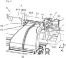
- FIG. 1 a small part of an exemplary embodiment of a system S according to the invention (here a motor vehicle), once the second equipment E2 (here an air intake) is coupled to the first equipment E1 (here an upper crossmember of the front facade of the vehicle S) in the immediate vicinity of a third equipment E3 (here a locking mechanism for the front hood of the vehicle S).
- the second equipment E2 here an air intake
- the first equipment E1 here an upper crossmember of the front facade of the vehicle S
- E3 here a locking mechanism for the front hood of the vehicle S.
- the first E1 equipment is here suitable for being installed transversely (i.e. mainly in the transverse direction Y) in the front part of the S system, at the level of the front facade.
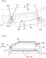
- the first equipment E1 comprises a first coupling element EC1 comprising a first housing L1 open on two adjoining faces, and a second coupling element EC2 comprising a second housing L2 open on two adjoining faces and oriented towards the first housing L1.
- the two open faces of the first housing L1, as of the second housing L2 have normals which are substantially parallel respectively to the vertical Z and transverse Y directions.
- the second equipment E2 comprises first F1 and second F2 opposite faces and provided respectively with first P1 and second P2 projecting walls.
- first face F1 is located on the right and the second face F2 is located on the left (when placed in front of the vehicle S looking towards its rear part).
- the first projecting wall P1 is introduced into the first housing L1 via its two open faces by an oblique translation of the second equipment E2 (materialized by the arrow FL1 of the figure 5 ).
- This oblique translation (arrow FL1) advantageously makes it possible to pass right next to the third equipment E3 without touching it in order to carry out part of the coupling, namely that of the right part of the second equipment E2 (via the first projecting wall P1) to the first coupling element EC1 of the first equipment E1 (via its first housing L1).
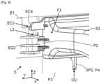
- the second projecting wall P2 is introduced into the second housing L2 via its two open faces by a rotation of the second equipment E2 around a virtual axis perpendicular to the first projecting wall P1 (and materialized by the arrows FL2 of the Figures 6 and 7 ).
- This rotation here downwards (arrows FL2), advantageously makes it possible to carry out the other part of the coupling, namely that of the left part of the second equipment E2 (via the second projecting wall P2) to the second coupling element EC2 of the first equipment E1 (via its second housing L2), still without touching the third equipment E3.
- the coupling of the second equipment E2 to the first equipment E1 therefore includes a first translation phase illustrated in the figure 5 and allowing here to pass right next to the third E3 equipment, and a second rotation phase illustrated on the Figures 6 and 7 .
- first translation phase illustrated in the figure 5 and allowing here to pass right next to the third E3 equipment
- second rotation phase illustrated on the Figures 6 and 7 .
- the first coupling element EC1 may be a wall which is partly secured to a front face of the first equipment E1 so as to define between it and this front face the first housing L1, and which may be reinforced by at least one rib.
- the second coupling element EC2 may be another wall which is partly secured to the front face of the first equipment E1 so as to define between it and this front face the second housing L2, and which may be reinforced by at least one rib.
- first EC1 and second EC2 coupling elements can be offset relative to each other.
- first P1 and second P2 projecting walls are also offset relative to each other. This makes it easier to avoid the third equipment E3 during the translation phase.
- the first equipment E1 can advantageously comprise a third coupling element EC3 spaced from the second housing L2 (here upwards).
- the second equipment E2 may comprise a fourth coupling element EC4 spaced from the second projecting wall P2 (here upwards) and cooperating with the third coupling element EC3 to ensure complementary coupling of the second equipment E2 to the first equipment E1.
- the complementary coupling advantageously makes it possible to immobilize the second equipment E2 relative to the first equipment E1 in the vertical direction Z.
- the third coupling element EC3 can be arranged in the form of a protuberance (for example a protruding edge), and the fourth coupling element EC4 can be arranged in the form of a clipping tab clipped onto the protuberance EC3.
- the clipping tab EC4 comprises a head which, once passed beyond (here below) the protuberance EC3, comes to be anchored on the latter (PC3).
- the first equipment E1 can advantageously comprise a third wall P3 located between the first EC1 and second EC2 coupling elements and provided with an opening (or cutout) OV.
- the second equipment E2 can comprise a fourth projecting wall P4 which is introduced into the opening OV during rotation of the second equipment E2 (see Figures 6 to 8 ).
- This is particularly advantageous because it not only ensures indexing of the positioning of the second equipment E2 relative to the first equipment E1, here following the transverse directions Y and vertical Z, but also guides the second equipment E2 during its rotation.
- the entrance (here upper) of the opening OV is flared (here on the left) in the area where contact is made first with the fourth projecting wall P4.
- the third wall P3 can be preceded (on its rear face) by a passage PP which communicates with the opening OV.
- the fourth projecting wall P4 may comprise first SP1 and second SP2 sub-parts which are perpendicular to each other and introduced respectively into the passage PP and into the opening OV during the rotation of the second equipment E2.
- This is advantageous because it makes it possible to additionally ensure indexing of the positioning of the second equipment E2 relative to the first equipment E1, here in the longitudinal direction X.
- the first sub-part SP1 is substantially in contact with the rear face of the third wall P3, it is certain that the first P1 and second P2 projecting walls are respectively housed in the first L1 and second L2 housings.
Landscapes
- Engineering & Computer Science (AREA)
- Chemical & Material Sciences (AREA)
- Combustion & Propulsion (AREA)
- Transportation (AREA)
- Mechanical Engineering (AREA)
- Casings For Electric Apparatus (AREA)
- Connection Of Plates (AREA)
- Body Structure For Vehicles (AREA)
Claims (10)
- System (S) mit einer ersten Einrichtung (E1), mit der eine zweite Einrichtung (E2) gekoppelt ist, wobei die erste Einrichtung (E1) erste (EC1) und zweite (EC2) Kopplungselemente aufweist, die jeweils erste (L1) und zweite (L2) offene Aufnahmen auf zwei sich verbindenden Flächen aufweisen, dadurch gekennzeichnet, dass die zweite Einrichtung (E2) zwei gegenüberliegende Flächen (F1, F2) aufweist, die jeweils mit einer ersten (P1) und einer zweiten (P2) vorstehenden Wand versehen sind, wobei die erste vorstehende Wand (P1) durch eine Schrägverschiebung der zweiten Einrichtung in die erste Aufnahme (L1) über ihre beiden offenen Flächen eingeführt wird (E2), wobei die zweite vorspringende Wand (P2) in das zweite Gehäuse (L2) über ihre beiden offenen Flächen durch eine Drehung der zweiten Einrichtung (E2) um eine virtuelle Achse senkrecht zu der ersten vorspringenden Wand (P1) eingeführt wird.
- System nach Anspruch 1, dadurch gekennzeichnet, dass die erste Einrichtung (E1) ein drittes Kopplungselement (EC3) aufweist, das von dem zweiten Gehäuse (L2) beabstandet ist, und dass die zweite Einrichtung (E2) ein viertes Kopplungselement (EC4) aufweist, das von der zweiten vorstehenden Wand (P2) beabstandet ist und mit dem dritten Kopplungselement (EC3) zusammenwirkt, um eine komplementäre Kopplung der zweiten Einrichtung (E2) mit der ersten Einrichtung (E1) sicherzustellen.
- System nach Anspruch 2, dadurch gekennzeichnet, dass das dritte Kopplungselement (EC3) als ein Vorsprung und das vierte Kopplungselement (EC4) als eine an den Vorsprung (EC3) angeklippte Klipplasche angeordnet ist.
- System nach einem der Ansprüche 1 bis 3, dadurch gekennzeichnet, dass die erste Einrichtung (E1) eine dritte Wand (P3) umfasst, die zwischen dem ersten (EC1) und dem zweiten (EC2) Kopplungselement angeordnet ist und mit einer Öffnung (OV) versehen ist, und dass die zweite Einrichtung (E2) eine vierte vorstehende Wand (P4) umfasst, die bei der Drehung der zweiten Einrichtung (E2) in die Öffnung (OV) eingeführt wird.
- System nach Anspruch 4, dadurch gekennzeichnet, dass der dritten Wand (P3) ein Durchgang (PP) vorangeht, der mit der Öffnung (OV) in Verbindung steht, und dass die vierte vorstehende Wand (P4) erste (SP1) und zweite (SP2) senkrechte Teilabschnitte aufweist, die jeweils in den Durchgang (PP) und die Öffnung (OV) bei der Drehung der zweiten Einrichtung (E2) eingeführt werden.
- System nach einem der Ansprüche 1 bis 5, dadurch gekennzeichnet, dass das erste (EC1) und das zweite (EC2) Kopplungselement zueinander versetzt sind und die erste (P1) und die zweite (P2) hervorstehende Wand zueinander versetzt sind.
- System nach einem der Ansprüche 1 bis 6, dadurch gekennzeichnet, dass es ein Fahrzeug bildet.
- System nach Anspruch 7, dadurch gekennzeichnet, dass die erste Einrichtung (E1) ein oberer Querträger einer vorderen Fassade ist.
- System nach Anspruch 7 oder 8, dadurch gekennzeichnet, dass die zweite Einrichtung (E2) ein Lufteinlass ist, der zum Sammeln und Kanalisieren von Luft geeignet ist.
- System nach einem der Ansprüche 7 bis 9, dadurch gekennzeichnet, dass es ein Kraftfahrzeug bildet.
Applications Claiming Priority (2)
| Application Number | Priority Date | Filing Date | Title |
|---|---|---|---|
| FR2105563A FR3123301B1 (fr) | 2021-05-28 | 2021-05-28 | Couplage d’équipements d’un système dans un environnement fortement contraint |
| PCT/FR2022/050786 WO2022248787A1 (fr) | 2021-05-28 | 2022-04-26 | Couplage d'équipements d'un système dans un environnement fortement contraint |
Publications (2)
| Publication Number | Publication Date |
|---|---|
| EP4347296A1 EP4347296A1 (de) | 2024-04-10 |
| EP4347296B1 true EP4347296B1 (de) | 2025-02-19 |
Family
ID=76920935
Family Applications (1)
| Application Number | Title | Priority Date | Filing Date |
|---|---|---|---|
| EP22735531.0A Active EP4347296B1 (de) | 2021-05-28 | 2022-04-26 | Kopplung von ausrüstungen eines systems in einer stark eingegrenzten umgebung |
Country Status (3)
| Country | Link |
|---|---|
| EP (1) | EP4347296B1 (de) |
| FR (1) | FR3123301B1 (de) |
| WO (1) | WO2022248787A1 (de) |
Family Cites Families (5)
| Publication number | Priority date | Publication date | Assignee | Title |
|---|---|---|---|---|
| FR2105563A5 (en) | 1970-09-11 | 1972-04-28 | Universal Oil Prod Co | Synergistic antiozonant mixture for rubber - comprising aromatic p-phenylenediamines |
| FR3003207B1 (fr) * | 2013-03-14 | 2015-03-13 | Renault Sa | "valise de refroidissement comportant des moyens de rattrapage des dispersions de fabrication" |
| FR3018478B1 (fr) | 2014-03-17 | 2016-03-11 | Renault Sas | Assemblage d'un guide d'air a un element structurel de vehicule automobile et vehicule correspondant |
| WO2017002146A1 (ja) * | 2015-06-30 | 2017-01-05 | 本田技研工業株式会社 | 自動車の吸気ダクト固定構造 |
| DE102015118726A1 (de) * | 2015-11-02 | 2017-05-04 | Dr. Ing. H.C. F. Porsche Aktiengesellschaft | Luftführungsvorrichtung für ein Fahrzeug |
-
2021
- 2021-05-28 FR FR2105563A patent/FR3123301B1/fr active Active
-
2022
- 2022-04-26 WO PCT/FR2022/050786 patent/WO2022248787A1/fr not_active Ceased
- 2022-04-26 EP EP22735531.0A patent/EP4347296B1/de active Active
Also Published As
| Publication number | Publication date |
|---|---|
| FR3123301A1 (fr) | 2022-12-02 |
| EP4347296A1 (de) | 2024-04-10 |
| FR3123301B1 (fr) | 2023-04-14 |
| WO2022248787A1 (fr) | 2022-12-01 |
Similar Documents
| Publication | Publication Date | Title |
|---|---|---|
| FR3125272A1 (fr) | Déflecteur aérodynamique destiné à être fixé contre le soubassement de caisse d’un véhicule automobile et pourvu de moyens de pré-maintien | |
| EP4347296B1 (de) | Kopplung von ausrüstungen eines systems in einer stark eingegrenzten umgebung | |
| EP2922730B1 (de) | Anordnung eines fronts eines kraftfahrzeuges mit einem an dem frontshild von einer externen sperre befestigten grill | |
| EP3165059B1 (de) | Baugruppe zur befestigung eines elektronischen gehäuses und mit einer derartigen baugruppe ausgerüstetes fahrzeug | |
| EP2870056B1 (de) | Unterer querträger zur öffnung einer schalldichten windschutzscheibe | |
| EP4135997B1 (de) | Oberer querträger für ein kraftfahrzeug | |
| WO2017089720A1 (fr) | Dispositif de montage d'un radar pour véhicule automobile | |
| FR3134859A1 (fr) | Équipement à pièce adaptée au clippage double | |
| FR3063126B1 (fr) | Protection pour gaine de conducteur electrique ou de fluide de vehicule automobile | |
| EP3898390A1 (de) | Element für fahrgastzelle eines kraftfahrzeugs und anordnung mit solch einem element für fahrgastzelle | |
| WO2008017774A1 (fr) | Ouvrant de vehicule automobile comprenant un raidisseur et vehicule muni un tel ouvrant | |
| EP4626753A1 (de) | Fahrzeug mit einem kofferraum mit elementen zur montage unsichtbarer trägerplattenträger | |
| FR2937926A1 (fr) | Support multifonction pour vehicule automobile. | |
| EP3658417B1 (de) | Vorhalteclip mit funktionsspiel | |
| FR3040677A1 (fr) | Agencement d'un passage de roue d'un vehicule automobile | |
| EP3254903B1 (de) | Fixierteil für verkleidungselemente auf einer seitlichen struktur eines kraftfahrzeugs | |
| FR3132872A1 (fr) | Pièce d’interface pour l’étanchéité entre un équipement et une grille d’entrée d’air d’un pare-chocs de véhicule terrestre | |
| FR3138172A1 (fr) | Équipement à double clip, pour un système | |
| FR3143488A1 (fr) | Support de plancher intermédiaire d’un coffre de véhicule automobile, coffre de véhicule automobile et véhicule automobile comportant un tel coffre | |
| WO2024069064A1 (fr) | Pièce de renfort pour une partie avant supérieure à bords repliés d'une aile de véhicule automobile | |
| WO2015007968A1 (fr) | Dispositif de maintien de cable(s) et de support d'un boitier de commande, pour la traversee d'un ouverture definie dans un equipement lors du montage du boitier de commande sur ledit equipement | |
| FR3139784A1 (fr) | Armature de pare-chocs à joint à appui renforcé pour un véhicule | |
| FR2994232A1 (fr) | Attache elastique, dispositif d'attache et procede de fabrication correspondant | |
| FR2989663A1 (fr) | Vehicule avec deflecteur modulaire d'accostage de pare-choc. | |
| FR2851752A1 (fr) | Element de fixation d'extremite de joint de porte |
Legal Events
| Date | Code | Title | Description |
|---|---|---|---|
| STAA | Information on the status of an ep patent application or granted ep patent |
Free format text: STATUS: UNKNOWN |
|
| STAA | Information on the status of an ep patent application or granted ep patent |
Free format text: STATUS: THE INTERNATIONAL PUBLICATION HAS BEEN MADE |
|
| PUAI | Public reference made under article 153(3) epc to a published international application that has entered the european phase |
Free format text: ORIGINAL CODE: 0009012 |
|
| STAA | Information on the status of an ep patent application or granted ep patent |
Free format text: STATUS: REQUEST FOR EXAMINATION WAS MADE |
|
| 17P | Request for examination filed |
Effective date: 20231211 |
|
| AK | Designated contracting states |
Kind code of ref document: A1 Designated state(s): AL AT BE BG CH CY CZ DE DK EE ES FI FR GB GR HR HU IE IS IT LI LT LU LV MC MK MT NL NO PL PT RO RS SE SI SK SM TR |
|
| DAV | Request for validation of the european patent (deleted) | ||
| DAX | Request for extension of the european patent (deleted) | ||
| GRAP | Despatch of communication of intention to grant a patent |
Free format text: ORIGINAL CODE: EPIDOSNIGR1 |
|
| STAA | Information on the status of an ep patent application or granted ep patent |
Free format text: STATUS: GRANT OF PATENT IS INTENDED |
|
| INTG | Intention to grant announced |
Effective date: 20240920 |
|
| GRAS | Grant fee paid |
Free format text: ORIGINAL CODE: EPIDOSNIGR3 |
|
| GRAA | (expected) grant |
Free format text: ORIGINAL CODE: 0009210 |
|
| STAA | Information on the status of an ep patent application or granted ep patent |
Free format text: STATUS: THE PATENT HAS BEEN GRANTED |
|
| AK | Designated contracting states |
Kind code of ref document: B1 Designated state(s): AL AT BE BG CH CY CZ DE DK EE ES FI FR GB GR HR HU IE IS IT LI LT LU LV MC MK MT NL NO PL PT RO RS SE SI SK SM TR |
|
| REG | Reference to a national code |
Ref country code: GB Ref legal event code: FG4D Free format text: NOT ENGLISH |
|
| REG | Reference to a national code |
Ref country code: CH Ref legal event code: EP |
|
| REG | Reference to a national code |
Ref country code: DE Ref legal event code: R096 Ref document number: 602022010898 Country of ref document: DE |
|
| REG | Reference to a national code |
Ref country code: IE Ref legal event code: FG4D Free format text: LANGUAGE OF EP DOCUMENT: FRENCH |
|
| REG | Reference to a national code |
Ref country code: DE Ref legal event code: R084 Ref document number: 602022010898 Country of ref document: DE |
|
| REG | Reference to a national code |
Ref country code: NL Ref legal event code: MP Effective date: 20250219 |
|
| PG25 | Lapsed in a contracting state [announced via postgrant information from national office to epo] |
Ref country code: RS Free format text: LAPSE BECAUSE OF FAILURE TO SUBMIT A TRANSLATION OF THE DESCRIPTION OR TO PAY THE FEE WITHIN THE PRESCRIBED TIME-LIMIT Effective date: 20250519 |
|
| PG25 | Lapsed in a contracting state [announced via postgrant information from national office to epo] |
Ref country code: FI Free format text: LAPSE BECAUSE OF FAILURE TO SUBMIT A TRANSLATION OF THE DESCRIPTION OR TO PAY THE FEE WITHIN THE PRESCRIBED TIME-LIMIT Effective date: 20250219 |
|
| PG25 | Lapsed in a contracting state [announced via postgrant information from national office to epo] |
Ref country code: PL Free format text: LAPSE BECAUSE OF FAILURE TO SUBMIT A TRANSLATION OF THE DESCRIPTION OR TO PAY THE FEE WITHIN THE PRESCRIBED TIME-LIMIT Effective date: 20250219 |
|
| PGFP | Annual fee paid to national office [announced via postgrant information from national office to epo] |
Ref country code: DE Payment date: 20250319 Year of fee payment: 4 |
|
| PG25 | Lapsed in a contracting state [announced via postgrant information from national office to epo] |
Ref country code: ES Free format text: LAPSE BECAUSE OF FAILURE TO SUBMIT A TRANSLATION OF THE DESCRIPTION OR TO PAY THE FEE WITHIN THE PRESCRIBED TIME-LIMIT Effective date: 20250219 |
|
| REG | Reference to a national code |
Ref country code: LT Ref legal event code: MG9D |
|
| PG25 | Lapsed in a contracting state [announced via postgrant information from national office to epo] |
Ref country code: IS Free format text: LAPSE BECAUSE OF FAILURE TO SUBMIT A TRANSLATION OF THE DESCRIPTION OR TO PAY THE FEE WITHIN THE PRESCRIBED TIME-LIMIT Effective date: 20250619 Ref country code: NO Free format text: LAPSE BECAUSE OF FAILURE TO SUBMIT A TRANSLATION OF THE DESCRIPTION OR TO PAY THE FEE WITHIN THE PRESCRIBED TIME-LIMIT Effective date: 20250519 |
|
| PG25 | Lapsed in a contracting state [announced via postgrant information from national office to epo] |
Ref country code: NL Free format text: LAPSE BECAUSE OF FAILURE TO SUBMIT A TRANSLATION OF THE DESCRIPTION OR TO PAY THE FEE WITHIN THE PRESCRIBED TIME-LIMIT Effective date: 20250219 |
|
| PG25 | Lapsed in a contracting state [announced via postgrant information from national office to epo] |
Ref country code: HR Free format text: LAPSE BECAUSE OF FAILURE TO SUBMIT A TRANSLATION OF THE DESCRIPTION OR TO PAY THE FEE WITHIN THE PRESCRIBED TIME-LIMIT Effective date: 20250219 |
|
| PG25 | Lapsed in a contracting state [announced via postgrant information from national office to epo] |
Ref country code: LV Free format text: LAPSE BECAUSE OF FAILURE TO SUBMIT A TRANSLATION OF THE DESCRIPTION OR TO PAY THE FEE WITHIN THE PRESCRIBED TIME-LIMIT Effective date: 20250219 Ref country code: PT Free format text: LAPSE BECAUSE OF FAILURE TO SUBMIT A TRANSLATION OF THE DESCRIPTION OR TO PAY THE FEE WITHIN THE PRESCRIBED TIME-LIMIT Effective date: 20250620 |
|
| PG25 | Lapsed in a contracting state [announced via postgrant information from national office to epo] |
Ref country code: BG Free format text: LAPSE BECAUSE OF FAILURE TO SUBMIT A TRANSLATION OF THE DESCRIPTION OR TO PAY THE FEE WITHIN THE PRESCRIBED TIME-LIMIT Effective date: 20250219 Ref country code: GR Free format text: LAPSE BECAUSE OF FAILURE TO SUBMIT A TRANSLATION OF THE DESCRIPTION OR TO PAY THE FEE WITHIN THE PRESCRIBED TIME-LIMIT Effective date: 20250520 |
|
| REG | Reference to a national code |
Ref country code: AT Ref legal event code: MK05 Ref document number: 1768000 Country of ref document: AT Kind code of ref document: T Effective date: 20250219 |
|
| PG25 | Lapsed in a contracting state [announced via postgrant information from national office to epo] |
Ref country code: SE Free format text: LAPSE BECAUSE OF FAILURE TO SUBMIT A TRANSLATION OF THE DESCRIPTION OR TO PAY THE FEE WITHIN THE PRESCRIBED TIME-LIMIT Effective date: 20250219 |
|
| PG25 | Lapsed in a contracting state [announced via postgrant information from national office to epo] |
Ref country code: SM Free format text: LAPSE BECAUSE OF FAILURE TO SUBMIT A TRANSLATION OF THE DESCRIPTION OR TO PAY THE FEE WITHIN THE PRESCRIBED TIME-LIMIT Effective date: 20250219 |
|
| PG25 | Lapsed in a contracting state [announced via postgrant information from national office to epo] |
Ref country code: DK Free format text: LAPSE BECAUSE OF FAILURE TO SUBMIT A TRANSLATION OF THE DESCRIPTION OR TO PAY THE FEE WITHIN THE PRESCRIBED TIME-LIMIT Effective date: 20250219 |
|
| PG25 | Lapsed in a contracting state [announced via postgrant information from national office to epo] |
Ref country code: IT Free format text: LAPSE BECAUSE OF FAILURE TO SUBMIT A TRANSLATION OF THE DESCRIPTION OR TO PAY THE FEE WITHIN THE PRESCRIBED TIME-LIMIT Effective date: 20250219 |
|
| PG25 | Lapsed in a contracting state [announced via postgrant information from national office to epo] |
Ref country code: AT Free format text: LAPSE BECAUSE OF FAILURE TO SUBMIT A TRANSLATION OF THE DESCRIPTION OR TO PAY THE FEE WITHIN THE PRESCRIBED TIME-LIMIT Effective date: 20250219 |
|
| PG25 | Lapsed in a contracting state [announced via postgrant information from national office to epo] |
Ref country code: EE Free format text: LAPSE BECAUSE OF FAILURE TO SUBMIT A TRANSLATION OF THE DESCRIPTION OR TO PAY THE FEE WITHIN THE PRESCRIBED TIME-LIMIT Effective date: 20250219 Ref country code: CZ Free format text: LAPSE BECAUSE OF FAILURE TO SUBMIT A TRANSLATION OF THE DESCRIPTION OR TO PAY THE FEE WITHIN THE PRESCRIBED TIME-LIMIT Effective date: 20250219 |
|
| PG25 | Lapsed in a contracting state [announced via postgrant information from national office to epo] |
Ref country code: RO Free format text: LAPSE BECAUSE OF FAILURE TO SUBMIT A TRANSLATION OF THE DESCRIPTION OR TO PAY THE FEE WITHIN THE PRESCRIBED TIME-LIMIT Effective date: 20250219 |
|
| PG25 | Lapsed in a contracting state [announced via postgrant information from national office to epo] |
Ref country code: SK Free format text: LAPSE BECAUSE OF FAILURE TO SUBMIT A TRANSLATION OF THE DESCRIPTION OR TO PAY THE FEE WITHIN THE PRESCRIBED TIME-LIMIT Effective date: 20250219 |
|
| REG | Reference to a national code |
Ref country code: DE Ref legal event code: R097 Ref document number: 602022010898 Country of ref document: DE |
|
| REG | Reference to a national code |
Ref country code: CH Ref legal event code: H13 Free format text: ST27 STATUS EVENT CODE: U-0-0-H10-H13 (AS PROVIDED BY THE NATIONAL OFFICE) Effective date: 20251125 |
|
| PG25 | Lapsed in a contracting state [announced via postgrant information from national office to epo] |
Ref country code: LU Free format text: LAPSE BECAUSE OF NON-PAYMENT OF DUE FEES Effective date: 20250426 |
|
| PG25 | Lapsed in a contracting state [announced via postgrant information from national office to epo] |
Ref country code: MC Free format text: LAPSE BECAUSE OF FAILURE TO SUBMIT A TRANSLATION OF THE DESCRIPTION OR TO PAY THE FEE WITHIN THE PRESCRIBED TIME-LIMIT Effective date: 20250219 |
|
| PLBE | No opposition filed within time limit |
Free format text: ORIGINAL CODE: 0009261 |
|
| STAA | Information on the status of an ep patent application or granted ep patent |
Free format text: STATUS: NO OPPOSITION FILED WITHIN TIME LIMIT |
|
| REG | Reference to a national code |
Ref country code: BE Ref legal event code: MM Effective date: 20250430 |
|
| PG25 | Lapsed in a contracting state [announced via postgrant information from national office to epo] |
Ref country code: BE Free format text: LAPSE BECAUSE OF NON-PAYMENT OF DUE FEES Effective date: 20250430 |
|
| PG25 | Lapsed in a contracting state [announced via postgrant information from national office to epo] |
Ref country code: CH Free format text: LAPSE BECAUSE OF NON-PAYMENT OF DUE FEES Effective date: 20250430 |
|
| 26N | No opposition filed |
Effective date: 20251120 |
|
| PG25 | Lapsed in a contracting state [announced via postgrant information from national office to epo] |
Ref country code: IE Free format text: LAPSE BECAUSE OF NON-PAYMENT OF DUE FEES Effective date: 20250426 |
|
| PGFP | Annual fee paid to national office [announced via postgrant information from national office to epo] |
Ref country code: FR Payment date: 20260320 Year of fee payment: 5 |