EP4345323A2 - Türbaugruppe mit befestigungselement und montageverfahren - Google Patents
Türbaugruppe mit befestigungselement und montageverfahren Download PDFInfo
- Publication number
- EP4345323A2 EP4345323A2 EP24152104.6A EP24152104A EP4345323A2 EP 4345323 A2 EP4345323 A2 EP 4345323A2 EP 24152104 A EP24152104 A EP 24152104A EP 4345323 A2 EP4345323 A2 EP 4345323A2
- Authority
- EP
- European Patent Office
- Prior art keywords
- component
- interior trim
- door
- section
- door assembly
- Prior art date
- Legal status (The legal status is an assumption and is not a legal conclusion. Google has not performed a legal analysis and makes no representation as to the accuracy of the status listed.)
- Pending
Links
Images


Classifications
-
- B—PERFORMING OPERATIONS; TRANSPORTING
- B60—VEHICLES IN GENERAL
- B60J—WINDOWS, WINDSCREENS, NON-FIXED ROOFS, DOORS, OR SIMILAR DEVICES FOR VEHICLES; REMOVABLE EXTERNAL PROTECTIVE COVERINGS SPECIALLY ADAPTED FOR VEHICLES
- B60J5/00—Doors
- B60J5/04—Doors arranged at the vehicle sides
- B60J5/0468—Fixation or mounting means specific for door components
- B60J5/0469—Fixation or mounting means specific for door components for door panels, e.g. hemming
-
- B—PERFORMING OPERATIONS; TRANSPORTING
- B60—VEHICLES IN GENERAL
- B60J—WINDOWS, WINDSCREENS, NON-FIXED ROOFS, DOORS, OR SIMILAR DEVICES FOR VEHICLES; REMOVABLE EXTERNAL PROTECTIVE COVERINGS SPECIALLY ADAPTED FOR VEHICLES
- B60J5/00—Doors
- B60J5/04—Doors arranged at the vehicle sides
- B60J5/0468—Fixation or mounting means specific for door components
-
- F—MECHANICAL ENGINEERING; LIGHTING; HEATING; WEAPONS; BLASTING
- F16—ENGINEERING ELEMENTS AND UNITS; GENERAL MEASURES FOR PRODUCING AND MAINTAINING EFFECTIVE FUNCTIONING OF MACHINES OR INSTALLATIONS; THERMAL INSULATION IN GENERAL
- F16B—DEVICES FOR FASTENING OR SECURING CONSTRUCTIONAL ELEMENTS OR MACHINE PARTS TOGETHER, e.g. NAILS, BOLTS, CIRCLIPS, CLAMPS, CLIPS OR WEDGES; JOINTS OR JOINTING
- F16B21/00—Means for preventing relative axial movement of a pin, spigot, shaft or the like and a member surrounding it; Stud-and-socket releasable fastenings
- F16B21/06—Releasable fastening devices with snap-action
- F16B21/07—Releasable fastening devices with snap-action in which the socket has a resilient part
-
- F—MECHANICAL ENGINEERING; LIGHTING; HEATING; WEAPONS; BLASTING
- F16—ENGINEERING ELEMENTS AND UNITS; GENERAL MEASURES FOR PRODUCING AND MAINTAINING EFFECTIVE FUNCTIONING OF MACHINES OR INSTALLATIONS; THERMAL INSULATION IN GENERAL
- F16B—DEVICES FOR FASTENING OR SECURING CONSTRUCTIONAL ELEMENTS OR MACHINE PARTS TOGETHER, e.g. NAILS, BOLTS, CIRCLIPS, CLAMPS, CLIPS OR WEDGES; JOINTS OR JOINTING
- F16B25/00—Screws that cut thread in the body into which they are screwed, e.g. wood screws
- F16B25/001—Screws that cut thread in the body into which they are screwed, e.g. wood screws characterised by the material of the body into which the screw is screwed
- F16B25/0021—Screws that cut thread in the body into which they are screwed, e.g. wood screws characterised by the material of the body into which the screw is screwed the material being metal, e.g. sheet-metal or aluminium
-
- F—MECHANICAL ENGINEERING; LIGHTING; HEATING; WEAPONS; BLASTING
- F16—ENGINEERING ELEMENTS AND UNITS; GENERAL MEASURES FOR PRODUCING AND MAINTAINING EFFECTIVE FUNCTIONING OF MACHINES OR INSTALLATIONS; THERMAL INSULATION IN GENERAL
- F16B—DEVICES FOR FASTENING OR SECURING CONSTRUCTIONAL ELEMENTS OR MACHINE PARTS TOGETHER, e.g. NAILS, BOLTS, CIRCLIPS, CLAMPS, CLIPS OR WEDGES; JOINTS OR JOINTING
- F16B35/00—Screw-bolts; Stay-bolts; Screw-threaded studs; Screws; Set screws
- F16B35/04—Screw-bolts; Stay-bolts; Screw-threaded studs; Screws; Set screws with specially-shaped head or shaft in order to fix the bolt on or in an object
- F16B35/06—Specially-shaped heads
-
- F—MECHANICAL ENGINEERING; LIGHTING; HEATING; WEAPONS; BLASTING
- F16—ENGINEERING ELEMENTS AND UNITS; GENERAL MEASURES FOR PRODUCING AND MAINTAINING EFFECTIVE FUNCTIONING OF MACHINES OR INSTALLATIONS; THERMAL INSULATION IN GENERAL
- F16B—DEVICES FOR FASTENING OR SECURING CONSTRUCTIONAL ELEMENTS OR MACHINE PARTS TOGETHER, e.g. NAILS, BOLTS, CIRCLIPS, CLAMPS, CLIPS OR WEDGES; JOINTS OR JOINTING
- F16B5/00—Joining sheets or plates, e.g. panels, to one another or to strips or bars parallel to them
- F16B5/06—Joining sheets or plates, e.g. panels, to one another or to strips or bars parallel to them by means of clamps or clips
- F16B5/0607—Joining sheets or plates, e.g. panels, to one another or to strips or bars parallel to them by means of clamps or clips joining sheets or plates to each other
- F16B5/0621—Joining sheets or plates, e.g. panels, to one another or to strips or bars parallel to them by means of clamps or clips joining sheets or plates to each other in parallel relationship
-
- F—MECHANICAL ENGINEERING; LIGHTING; HEATING; WEAPONS; BLASTING
- F16—ENGINEERING ELEMENTS AND UNITS; GENERAL MEASURES FOR PRODUCING AND MAINTAINING EFFECTIVE FUNCTIONING OF MACHINES OR INSTALLATIONS; THERMAL INSULATION IN GENERAL
- F16B—DEVICES FOR FASTENING OR SECURING CONSTRUCTIONAL ELEMENTS OR MACHINE PARTS TOGETHER, e.g. NAILS, BOLTS, CIRCLIPS, CLAMPS, CLIPS OR WEDGES; JOINTS OR JOINTING
- F16B5/00—Joining sheets or plates, e.g. panels, to one another or to strips or bars parallel to them
- F16B5/06—Joining sheets or plates, e.g. panels, to one another or to strips or bars parallel to them by means of clamps or clips
- F16B5/0607—Joining sheets or plates, e.g. panels, to one another or to strips or bars parallel to them by means of clamps or clips joining sheets or plates to each other
- F16B5/0621—Joining sheets or plates, e.g. panels, to one another or to strips or bars parallel to them by means of clamps or clips joining sheets or plates to each other in parallel relationship
- F16B5/0657—Joining sheets or plates, e.g. panels, to one another or to strips or bars parallel to them by means of clamps or clips joining sheets or plates to each other in parallel relationship at least one of the plates providing a raised structure, e.g. of the doghouse type, for connection with the clamps or clips of the other plate
-
- F—MECHANICAL ENGINEERING; LIGHTING; HEATING; WEAPONS; BLASTING
- F16—ENGINEERING ELEMENTS AND UNITS; GENERAL MEASURES FOR PRODUCING AND MAINTAINING EFFECTIVE FUNCTIONING OF MACHINES OR INSTALLATIONS; THERMAL INSULATION IN GENERAL
- F16B—DEVICES FOR FASTENING OR SECURING CONSTRUCTIONAL ELEMENTS OR MACHINE PARTS TOGETHER, e.g. NAILS, BOLTS, CIRCLIPS, CLAMPS, CLIPS OR WEDGES; JOINTS OR JOINTING
- F16B5/00—Joining sheets or plates, e.g. panels, to one another or to strips or bars parallel to them
- F16B5/06—Joining sheets or plates, e.g. panels, to one another or to strips or bars parallel to them by means of clamps or clips
- F16B5/0607—Joining sheets or plates, e.g. panels, to one another or to strips or bars parallel to them by means of clamps or clips joining sheets or plates to each other
- F16B5/0621—Joining sheets or plates, e.g. panels, to one another or to strips or bars parallel to them by means of clamps or clips joining sheets or plates to each other in parallel relationship
- F16B5/0664—Joining sheets or plates, e.g. panels, to one another or to strips or bars parallel to them by means of clamps or clips joining sheets or plates to each other in parallel relationship at least one of the sheets or plates having integrally formed or integrally connected snap-in-features
-
- F—MECHANICAL ENGINEERING; LIGHTING; HEATING; WEAPONS; BLASTING
- F16—ENGINEERING ELEMENTS AND UNITS; GENERAL MEASURES FOR PRODUCING AND MAINTAINING EFFECTIVE FUNCTIONING OF MACHINES OR INSTALLATIONS; THERMAL INSULATION IN GENERAL
- F16B—DEVICES FOR FASTENING OR SECURING CONSTRUCTIONAL ELEMENTS OR MACHINE PARTS TOGETHER, e.g. NAILS, BOLTS, CIRCLIPS, CLAMPS, CLIPS OR WEDGES; JOINTS OR JOINTING
- F16B5/00—Joining sheets or plates, e.g. panels, to one another or to strips or bars parallel to them
- F16B5/12—Fastening strips or bars to sheets or plates, e.g. rubber strips, decorative strips for motor vehicles, by means of clips
- F16B5/126—Fastening strips or bars to sheets or plates, e.g. rubber strips, decorative strips for motor vehicles, by means of clips at least one of the sheets, plates, bars or strips having integrally formed or integrally connected snap-in-features
-
- B—PERFORMING OPERATIONS; TRANSPORTING
- B60—VEHICLES IN GENERAL
- B60J—WINDOWS, WINDSCREENS, NON-FIXED ROOFS, DOORS, OR SIMILAR DEVICES FOR VEHICLES; REMOVABLE EXTERNAL PROTECTIVE COVERINGS SPECIALLY ADAPTED FOR VEHICLES
- B60J5/00—Doors
- B60J5/04—Doors arranged at the vehicle sides
- B60J5/0412—Lower door structure
- B60J5/0416—Assembly panels to be installed in doors as a module with components, e.g. lock or window lifter, attached thereto
-
- B—PERFORMING OPERATIONS; TRANSPORTING
- B60—VEHICLES IN GENERAL
- B60J—WINDOWS, WINDSCREENS, NON-FIXED ROOFS, DOORS, OR SIMILAR DEVICES FOR VEHICLES; REMOVABLE EXTERNAL PROTECTIVE COVERINGS SPECIALLY ADAPTED FOR VEHICLES
- B60J5/00—Doors
- B60J5/04—Doors arranged at the vehicle sides
- B60J5/0463—Conceptual assembling of door, i.e. how door frame parts should be fitted together to form door
Definitions
- the invention relates to a door assembly for a motor vehicle according to the preamble of claim 1 and a method according to the preamble of claim 17.
- a generic door assembly includes, among other things, a door skin, which can be formed, for example, by an inner door panel.
- a carrier component can be provided on the door skin, which is designed to carry at least one functional component to be arranged within an installation space formed in the motor vehicle.
- Such a carrier component can be, for example, an assembly carrier for a motor vehicle door, to which, for example, parts of a motor vehicle window lifter or at least one loudspeaker are attached.
- a door assembly includes an interior trim component, which is usually attached to the door skin with fastening means and covers the functional components, as in the US8,020,919 B2 shown.
- An important quality feature for the optimal attachment of the carrier component is a small gap between the interior trim component and the door skin.
- a small gap pattern can only be achieved with considerable effort if it is not possible to attach the interior lining component to the door skin. This is the case, for example, with a flat support component that covers the door skin. In this case, the interior trim component can only be attached to the support component. However, since the support component is attached to the door skin with a certain tolerance and If the interior lining component is in turn attached to the support component with a certain tolerance, tolerances are added up, which may increase the gap pattern. This deteriorates the visual quality of the door assembly.
- the present invention is therefore based on the object of improving a door assembly, in particular with a flat support component, and of optimizing the attachment of the interior trim component.
- a support component is fastened to the door skin with at least one fastening element, the at least one fastening element also being used according to the invention to fasten the interior lining component.
- a plurality of fastening elements are arranged on a peripheral edge of the carrier component. This allows maximum utilization of the area of the support component.
- the fastening element protrudes from the support component with a head section.
- the interior lining component is fixed to the head section. This makes it possible to attach the interior trim component to the at least one fastening element.
- the interior trim component can comprise, for example, a locking section with which the head section can interact.
- the locking section can be mechanically locked to the head section.
- the locking section can comprise a receptacle that can be widened.
- An widened receptacle can enable the head section to be received when the head section is pressed against the receptacle.
- the receptacle can be rigid.
- the head section can be pressed against the widened receptacle so that the receptacle widens until the head section can pass through the receptacle.
- the receptacle can narrow again.
- the receptacle is designed to provide an enlarged through-opening through elastically flexible side walls during the passage of the head section and, after the head section has passed through the recording has passed, to return to an original state with a smaller passage opening.
- the head section is a head section with a cross-sectional shape that tapers towards the tip, such as a spherical shape, a cone shape or a truncated cone shape.
- the cross-sectional shape of the head section can be T-shaped.
- Possible examples of a T-shaped cross-sectional shape include a mushroom-shaped and screw-head-shaped design of the head section, with the screw-head-shaped design in particular being able to use a ball head or a cylinder head.
- the at least one fastening element comprises an (elastically) deformable head section.
- a deformable head section can be compressed at least locally when the head section is pressed against the receptacle. This then allows the head section to pass through the receptacle. This means that a diameter of the head section perpendicular to the direction of insertion into the receptacle can be smaller during the passage through the receptacle than in a state after the head section has passed through the receptacle and a locking mechanism is provided via the head section.
- the head section comprises at least one locking element for locking the head section to the interior trim component.
- the at least one locking element can be formed by a locking hook. Suitable locking hooks can be formed by plastic clips.
- the plastic clips are molded onto the fastening element.
- the at least two locking elements can be bent towards one another so that the head section is at least locally deformable.
- the at least two locking elements can be designed such that the at least two locking elements can be bent towards one another by the pressure generated when the head section is inserted into the receptacle.
- the diameter of the head section can be reduced perpendicular to the insertion direction by bending the at least one locking element. By snapping back the at least one locking element after passing through the receptacle, the head section is then locked to the locking section of the interior trim component.
- the at least one fastening element comprises a shaft section that is connected to the door skin in a form-fitting and/or force-fitting manner.
- the door skin can have at least one through hole.
- the shaft section can protrude through the through hole through or into the door skin.
- the shaft section can be screwed to the door skin.
- the shaft section can have a threaded section with a thread for screwing to the door skin, via which the threaded section is screwed to the door skin.
- the shaft section is designed in a further embodiment to create an opening in the carrier component.
- the opening can be created at a suitable location in the carrier component.
- the suitable location can be indicated by a marking on the carrier component.
- the shaft section can be designed to create the opening in the support component with a pointed end that can penetrate through the support component when the support component is attached to the door skin. It is also conceivable that the threaded section is designed to create the opening in the support component when the support component is attached to the door skin.
- the thread of the threaded section can be designed as a self-tapping thread, for example.
- the support component can rest on the door skin.
- the support component can be fixed immovably to the door skin in a simple manner.
- elements arranged on the shaft section can be used to a limited extent to fix the support component.
- the elements can be realized, for example, by the thread of the threaded section, which interacts with an internal thread of the opening.
- the elements can be realized by changing the cross-sectional shape of the shaft section along a connecting axis between the door skin and the support component.
- a shoulder can be formed on the shaft section. The shoulder can be positioned in such a way that the support component rests with one flat side against the shoulder and with the other flat side against the door skin applied. It would then be possible, for example, to fix the support component between the shoulder and the door skin using the fastening element.
- the diameter of the shaft section can be increased at a step along the connection axis coming from the threaded section.
- the step can run perpendicular to the connection axis.
- the step can be formed in a ring shape on the shaft section. In one embodiment, the step is arranged along the connection axis on the threaded section.
- a further aspect of the present invention relates to a method for assembling the door assembly, in which the carrier component is fastened to the door skin using the at least one fastening element.
- the interior trim component is fastened to the carrier component using the at least one fastening element, which is also used for fastening the carrier component to the interior trim component, by securing the interior trim component to a head section of the at least one fastening element.
- the interior trim component can be connected to the head section of the at least one fastening element in a form-fitting and/or force-fitting manner.
- the interior trim component can be snapped into the head section.
- the interior trim component is fixed to the head section after the carrier component has been attached to the door skin.
- an opening can be created in the carrier component by means of the at least one fastening element.
- the breakthrough can be created by means of a threaded section of the at least one fastening element that has a self-tapping thread.
- a proposed assembly method is particularly suitable for the assembly of a proposed door assembly.
- the features and advantages explained above and below for design variants of a door assembly therefore also apply to design variants of an assembly method and vice versa.
- Fig.1 shows a door assembly with a door skin 1, a support component 2 and an interior trim component 3, wherein the support component 2 is fastened to the door skin 1 with - in this embodiment - four fastening elements 4, which in this embodiment are arranged on a peripheral edge of the support component 2.
- openings 21 are created on the support component 2 using the fastening elements 4, which can, for example, be marked in advance on the support component 2.
- the fastening elements 4 are then fastened to the door skin 1, so that the support component 2 is fastened to the door skin 1 using the fastening elements 4.
- the interior trim component 3 is arranged on the door skin 1 after the support component 2 has been arranged.
- a possible attachment surface for the interior trim component 3 on the door skin 1 can be hidden.
- the interior trim component 3 is also fastened by means of the fastening elements 4.
- the fastening elements 4 protrude from the carrier component 2 with a head section 42, with which the interior trim component 3 is mechanically locked in the embodiment shown.
- the fastening elements 4 protrude from the carrier component 2 with a head section 42, with which the interior trim component 3 is mechanically locked in the embodiment shown.
- other positive and/or non-positive connections are also conceivable and possible.
- Fig. 2 shows a fastening element 4, which is used to fasten a support component 2 and an interior trim component 3 to a door skin 1.
- the fastening element 4 comprises a head section 42, the tip of which is frusto-conical.
- the interior trim component 3 includes a latching portion 31 for attachment to the head portion 42. The head portion 42 and the latching portion 31 cooperate to connect the interior trim component 3 and the fastening element 4.
- the latching section 31 includes a receptacle 311 for connection to the head section 42, through which the head section 42 projects into the latching section 31.
- the frustoconical tip of the head section 42 is arranged inside the locking section 31. Since the base area of the frustoconical tip is larger than the cross-sectional shape of the receptacle 311, the head section 42 and the locking section 31 are mechanically locked together.
- Other versions of a positive connection or generally other positive and/or non-positive connections between the interior lining component 3 and the fastening element 4 are conceivable and possible.
- the locking section 31 and head section 42 can be joined together quickly and with little effort.
- the receptacle 311 is widened during insertion by the pressure of the conical surface of the truncated cone-shaped tip in a direction perpendicular to the insertion direction, so that the head section 42 can be inserted into the locking section 31.
- the head section 42 when the head section 42 is inserted into the receptacle 311, the head section 42 is compressed under the pressure of the receptacle 311 in a direction perpendicular to the insertion direction, so that the head section 42 can be inserted into the receptacle 311.
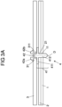
- the head section 42 comprises two bendable locking hooks 42a, 42b.
- the locking hooks 42a, 42b are formed by an injection-molded plastic clip.
- the head section 42 deforms in the area of the locking hooks 42a, 42b, i.e. the locking hooks 42a, 42b are bent towards each other.
- a combination of an expandable receptacle 311 and a compressible or constrictable head section 42 is also conceivable.
- the fastening element 4 can also have a locking section with the features of the locking section 31 and the interior trim component 3 can have a head section with the features of the head section 42.
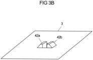
- the cross-sectional shape of the head section 42 is as in Fig. 3B shown, rectangular.
- the recording 311 is also rectangular. That is, the shape of the receptacle 311 is designed to allow passage of the possibly compressed or narrowed head section 42.
- a different geometry of the head section 42 and the receptacle 311 is also conceivable and possible.
- the receptacle 311 can be circular and the head section 42 can be round.
- the fastening element 4 comprises a shaft section 41 which is screwed to the door skin 1.
- the door skin 1 comprises a through hole 11 and the shaft section 41 comprises a threaded section 412 with a thread.
- the threaded section 412 is screwed into the through hole 11 on the door skin 1 in order to fix the carrier component 2 to the door skin 1.
- the support component 2 is pierced for attachment to the door skin 1 using the fastening element 4, whereby an opening 21 is created in the support component 2.
- the thread of the fastening element 4 is designed to be self-tapping.
- the fastening element 4 tapers towards an end opposite the head section 42. In the assembled door assembly, the end of the fastening element 4 opposite the head section 42 projects through the door skin 1.
- the carrier component 2 is fastened to the door skin 1 with the fastening element 4, with one side of the carrier component 2 resting against the door skin 1.
- the shoulder 411 is arranged along a connection axis D, which extends along the fastening element 4 from the head section 42 over the shaft section 41.
- paragraph 411 is reduced in size the cross-sectional shape of the shaft section 41 along the connecting axis D coming from the head section 42.
- the shoulder 411 is consequently characterized by an enlargement of the cross-sectional shape of the shaft section 41.
- the paragraph 411 extends orthogonally to the connecting axis D.
- the paragraph 411 is in the embodiment variant Fig. 3A designed as a disk-shaped enlargement of the cross-sectional shape of the shaft section 41.
- the magnification can have any geometric shape.
- the interior trim component 3 is fixed between the head section 42 and the paragraph 411, while the support component 2 is fixed between the door skin 1 and the paragraph 411.
- the support component 2 rests on the door skin 1 on one side and on the interior trim component 3 on the other side.
- the proposed solution basically also includes the following variants:
- Door assembly according to embodiment variant 1 characterized in that the head section (42) is connected to the interior trim component (3) in a form-fitting and/or force-fitting manner.
- Door assembly according to embodiment variant 2 characterized in that the interior trim component (3) has a latching section (31) which is mechanically latched to the head section (42) of the at least one fastening element (4).
- Door assembly according to one of embodiment variants 1 to 3, characterized in that the head section (42) is T-shaped in cross section.
- Door assembly according to one of embodiment variants 1 to 4, characterized in that the head section (42) comprises at least one elastically deformable locking element for fixing the interior lining component (3).
- Door assembly according to embodiment variant 5 characterized in that the at least one locking element is formed by a locking hook (42a, 42b).
- Door assembly according to one of the embodiment variants 5 or 6, characterized in that the at least one locking element is formed by an injection-molded plastic clip.
- Door assembly according to one of the embodiment variants 1 to 7, characterized in that several fastening elements (4) are arranged on a peripheral edge of the carrier component (2).
- the at least one fastening element (4) comprises a shaft section (41) which is connected to the door skin (1) in a form-fitting and/or force-fitting manner.
- Door assembly according to embodiment variant 9 characterized in that the shaft section (41) is designed to create an opening (21) in the carrier component (2) when attaching the carrier component (2) to the door skin (1).
- Door assembly according to one of the embodiment variants 9 or 10, characterized in that the shaft portion (41) comprises a threaded portion (412) with a thread, via which the threaded portion (412) is screwed to the door skin (1).
- Door assembly according to embodiment variant 14 characterized in that the interior trim component (3) rests against the shoulder (411).
- Method according to embodiment variant 17 characterized in that the interior lining component (3) is connected to the head section (42) of the at least one fastening element (4) in a form-fitting and/or force-fitting manner.
Landscapes
- Engineering & Computer Science (AREA)
- General Engineering & Computer Science (AREA)
- Mechanical Engineering (AREA)
- Vehicle Interior And Exterior Ornaments, Soundproofing, And Insulation (AREA)
- Window Of Vehicle (AREA)
- Connection Of Plates (AREA)
Abstract
Description
- Die Erfindung betrifft eine Türbaugruppe für ein Kraftfahrzeug nach dem Oberbegriff des Anspruchs 1 sowie ein Verfahren nach dem Oberbegriff des Anspruchs 17.
- Eine gattungsgemäße Türbaugruppe umfasst unter anderem eine Türhaut, die zum Beispiel durch ein Türinnenblech gebildet sein kann. An der Türhaut kann ein Trägerbauteil vorgesehen sein, das dazu ausgebildet ist, wenigstens eine innerhalb eines in dem Kraftfahrzeug ausgebildeten Bauraums anzuordnende Funktionskomponente zu tragen. Ein solches Trägerbauteil kann zum Beispiel ein Aggregateträger für eine Kraftfahrzeugtür sein, an dem zum Beispiel Teile eines Kraftfahrzeugfensterhebers oder mindestens ein Lautsprecher befestigt sind. Weiterhin umfasst eine Türbaugruppe ein Innenverkleidungsbauteil, das regelmäßig mit Befestigungsmitteln an der Türhaut befestigt ist und die Funktionskomponenten verdeckt, wie in der
US 8,020,919 B2 gezeigt. Ein wichtiges Qualitätsmerkmal für die optimale Anbringung des Trägerbauteils ist ein kleines Spaltbild zwischen dem Innenverkleidungsbauteil und der Türhaut. - Ein kleines Spaltbild ist aus Fertigungsgründen nur mit erheblichem Aufwand erreichbar, wenn keine Anbringung des Innenverkleidungsbauteils an der Türhaut möglich ist. Dies ist zum Beispiel der Fall bei einem flächigen Trägerbauteil, das die Türhaut überdeckt. In dem Fall kann das Innenverkleidungsbauteil nur an dem Trägerbauteil angebracht werden. Da das Trägerbauteil jedoch mit einer gewissen Toleranz an der Türhaut angebracht ist und das Innenverkleidungsbauteil wiederum mit einer gewissen Toleranz an dem Trägerbauteil angebracht ist, kommt es zu einer Aufsummierung von Toleranzen, die das Spaltbild unter Umständen vergrößert. Dadurch verschlechtert sich die optische Qualitätsanmutung der Türbaugruppe.
- Der vorliegenden Erfindung liegt daher die Aufgabe zugrunde, eine Türbaugruppe, insbesondere mit einem flächigen Trägerbauteil, zu verbessern und die Anbringung des Innenverkleidungsbauteils zu optimieren.
- Diese Aufgabe wird mit der Türbaugruppe des Anspruchs 1 und einem Verfahren zur Montage der Türbaugruppe nach Anspruch 17 gelöst.
- Bei einer vorgeschlagenen Türbaugruppe ist ein Trägerbauteil mit mindestens einem Befestigungselement an der Türhaut befestigt, wobei das mindestens eine Befestigungselement erfindungsgemäß auch zur Befestigung des Innenverkleidungsbauteils genutzt ist. In einem Ausführungsbeispiel sind mehrere Befestigungselemente an einem umfangseitigen Rand des Trägerbauteils angeordnet. Dadurch ist eine maximale Ausnutzung der Fläche des Trägerbauteils möglich. Zur Befestigung des Innenverkleidungsbauteils steht das Befestigungselement an dem Trägerbauteil mit einem Kopfabschnitt vor. An dem Kopfabschnitt ist das Innenverkleidungsbauteil festgelegt. Derart ist eine Befestigung des Innenverkleidungsbauteils an dem mindestens einen Befestigungselement ermöglicht.
- Zur Festlegung an dem Kopfabschnitt kann das Innenverkleidungsbauteil beispielsweise einen Rastabschnitt, mit dem der Kopfabschnitt zusammenwirken kann, umfassen. Insbesondere kann der Rastabschnitt mit dem Kopfabschnitt mechanisch verrastet sein.
- Der Rastabschnitt kann in einer Ausführung eine Aufnahme umfassen, die weitbar sein kann. Eine weitbare Aufnahme kann ein Aufnehmen des Kopfabschnitts ermöglichen, wenn der Kopfabschnitt gegen die Aufnahme gedrückt wird. Alternativ kann die Aufnahme starr sein. Beim Vorsehen einer weitbaren Aufnahme kann der Kopfabschnitt gegen die weitbare Aufnahme gedrückt werden, so dass die Aufnahme sich weitet bis der Kopfabschnitt die Aufnahme passieren kann. Nachdem der Kopfabschnitt die Aufnahme passiert hat, kann sich die Aufnahme wieder verengen. Mit anderen Worten ist die Aufnahme ausgebildet, während der Passage des Kopfabschnitts eine vergrößerte Durchgangsöffnung durch elastisch nachgiebige Seitenwände bereitzustellen und, nachdem der Kopfabschnitt die Aufnahme passiert hat, in einen Ursprungszustand mit kleinerer Durchgangsöffnung zurückzukehren.
- Eine mögliche Ausführung des Kopfabschnitts ist ein Kopfabschnitt mit einer sich zur Spitze hin verjüngenden Querschnittsform wie beispielsweise einer Kugelform, Kegelform oder Kegelstumpfform. Zur Herstellung einer formschlüssigen und/oder kraftschlüssigen Verbindung zwischen dem Kopfabschnitt und dem Innenverkleidungsbauteil kann die Querschnittsform des Kopfabschnitts T-förmig sein. Mögliche Beispiele für eine T-förmige Querschnittsform umfassen eine pilzförmige und schraubenkopfförmige Ausführung des Kopfabschnitts, wobei bei der schraubenkopfförmigen Ausführung insbesondere ein Kugelkopf oder ein Zylinderkopf verwendet werden können.
- In einem alternativen Ausführungsbeispiel umfasst das mindestens eine Befestigungselement einen (elastisch) verformbaren Kopfabschnitt. Ein verformbarer Kopfabschnitt kann zumindest lokal komprimiert werden, wenn der Kopfabschnitt gegen die Aufnahme gedrückt wird. Dadurch kann dann der Kopfabschnitt die Aufnahme passieren. Das heißt, ein Durchmesser des Kopfabschnitts senkrecht zur Einführrichtung in die Aufnahme kann während der Passage durch die Aufnahme kleiner sein, als in einem Zustand, nachdem der Kopfabschnitt die Aufnahme passiert hat und über den Kopfabschnitt eine Verrastung bereitgestellt ist.
- In einem Ausführungsbeispiel umfasst der Kopfabschnitt mindestens ein Rastelement zum Verrasten des Kopfabschnitts mit dem Innenverkleidungsbauteil. Das mindestens eine Rastelement kann durch einen Rasthaken gebildet sein. Geeignete Rasthaken können durch Kunststoffclips gebildet sein. In einer Ausführung sind die Kunststoffclips an das Befestigungselement angespritzt. In einer Ausführung mit mindestens zwei Rastelementen können die mindestens zwei Rastelemente zueinander hin biegbar sein, so dass der Kopfabschnitt zumindest lokal verformbar ist. Dazu können die mindestens zwei Rastelemente so ausgebildet sein, dass die mindestens zwei Rastelemente durch den beim Einstecken des Kopfabschnitts in die Aufnahme erzeugten Druck zueinander hinbiegbar sind.
- Grundsätzlich kann durch das Verbiegen des mindestens einen Rastelementes ein Durchmesser des Kopfabschnitts senkrecht zur Einsteckrichtung verkleinerbar sein. Durch das Zurückschnappen des mindestens einen Rastelementes nach der Passage durch die Aufnahme ist der Kopfabschnitt dann mit dem Rastabschnitt des Innenverkleidungsbauteils verrastet.
- In einem Ausführungsbeispiel umfasst das mindestens eine Befestigungselement einen Schaftabschnitt, der formschlüssig und/oder kraftschlüssig mit der Türhaut verbunden ist. Um eine formschlüssige und/oder kraftschlüssige Verbindung mit dem mindestens einen Befestigungselement zu ermöglichen, kann die Türhaut mindestens ein Durchgangsloch aufweisen. Durch das Durchgangsloch kann der Schaftabschnitt durch oder in die Türhaut ragen. Beispielsweise kann der Schaftabschnitt mit der Türhaut verschraubt sein. Der Schaftabschnitt kann zum Verschrauben mit der Türhaut einen Gewindeabschnitt mit einem Gewinde aufweisen, über das der Gewindeabschnitt mit der Türhaut verschraubt ist.
- Um das Trägerbauteil mit dem mindestens einen Befestigungselement an der Türhaut zu befestigen, ist der Schaftabschnitt in einem weiteren Ausführungsbeispiel zum Erzeugen eines Durchbruchs im Trägerbauteil ausgebildet. Dadurch kann bei der Befestigung des Trägerbauteils an der Türhaut der Durchbruch an einer geeigneten Stelle im Trägerbauteil erzeugt werden. Beispielsweise kann die geeignete Stelle durch eine Markierung auf dem Trägerbauteil angezeigt sein. Im Hinblick auf die Fertigung ist ein Erzeugen des Durchbruchs beim Befestigen des Trägerbauteils kostengünstiger und zeitsparender im Vergleich zu beispielsweise einem vorgefertigten Durchbruch.
- Der Schaftabschnitt kann zum Erzeugen des Durchbruchs im Trägerbauteil mit einem spitzen Ende ausgebildet sein, das bei der Befestigung des Trägerbauteils an der Türhaut durch das Trägerbauteil hindurch stechen kann. Ebenso ist es denkbar, dass der Gewindeabschnitt zum Erzeugen des Durchbruchs im Trägerbauteil bei der Befestigung des Trägerbauteils an der Türhaut ausgebildet ist. Das Gewinde des Gewindeabschnitts kann zum Beispiel als ein selbstschneidendes Gewinde ausgebildet sein.
- Das Trägerbauteil kann an der Türhaut anliegen. Ebenso kann das Trägerbauteil in einfacher Weise an der Türhaut unbeweglich fixiert sein. Zum Beispiel können am Schaftabschnitt angeordnete Elemente eingeschränkt zur Fixierung des Trägerbauteils genutzt sein. Die Elemente können zum Beispiel durch das Gewinde des Gewindeabschnitts verwirklicht sein, das mit einem Innengewinde des Durchbruchs zusammenwirkt. Ebenso können die Elemente durch eine Änderung der Querschnittsform des Schaftabschnitts entlang einer Verbindungsachse zwischen der Türhaut und dem Trägerbauteil verwirklicht sein. Beispielsweise kann ein Absatz am Schaftabschnitt ausgebildet sein. Der Absatz kann so positioniert sein, dass das Trägerbauteil mit der einen flächigen Seite an dem Absatz anliegt und mit der anderen flächigen Seite an der Türhaut anliegt. Es wäre dann zum Beispiel möglich, das Trägerbauteil mittels des Befestigungselements zwischen dem Absatz und der Türhaut festzulegen.
- Insbesondere bei einer runden Querschnittsform kann der Durchmesser des Schaftabschnitts entlang der Verbindungsachse vom Gewindeabschnitt kommend an einem Absatz vergrößert sein. Der Absatz kann senkrecht zu der Verbindungsachse verlaufen. Der Absatz kann ringförmig am Schaftabschnitt ausgebildet sein. In einem Ausführungsbeispiel ist der Absatz entlang der Verbindungsachse am Gewindeabschnitt angeordnet.
- Ein weiterer Aspekt der vorliegenden Erfindung betrifft ein Verfahren zur Montage der Türbaugruppe, bei dem das Trägerbauteil mit dem mindestens einen Befestigungselement an der Türhaut befestigt wird. Erfindungsgemäß wird das Innenverkleidungsbauteil über das mindestens eine Befestigungselement, das auch für die Befestigung des Trägerbauteils an dem Innenverkleidungsbauteil genutzt ist, an dem Trägerbauteil befestigt, indem das Innenverkleidungsbauteil an einem Kopfabschnitt des mindestens einen Befestigungselements festgelegt wird.
- Für die Befestigung des Innenverkleidungsbauteils an dem Trägerbauteil kann das Innenverkleidungsbauteil mit dem Kopfabschnitt des mindestens einen Befestigungselements formschlüssig und/oder kraftschlüssig verbunden werden. Beispielsweise kann das Innenverkleidungsbauteil an dem Kopfabschnitt eingeschnappt werden.
- In einer Ausführungsvariante des Verfahrens wird das Innenverkleidungsbauteil an dem Kopfabschnitt festgelegt, nachdem das Trägerbauteil an der Türhaut befestigt wurde.
- Für die Befestigung des Trägerbauteils an der Türhaut kann mittels des mindestens einen Befestigungselements ein Durchbruch im Trägerbauteil erzeugt werden. Beispielsweise kann der Durchbruch mittels eines Gewindeabschnitts des mindestens einen Befestigungselements, der ein selbstschneidendes Gewinde aufweist, erzeugt werden.
- Ein vorgeschlagenes Montageverfahren eignet sich insbesondere für die Montage einer vorgeschlagenen Türbaugruppe. Vorstehend und nachstehend für Ausführungsvarianten einer Türbaugruppe erläuterte Merkmale und Vorteile gelten somit auch für Ausführungsvarianten eines Montageverfahrens und umgekehrt.
- Der der Erfindung zugrunde liegende Gedanke soll nachfolgend anhand der in den Figuren dargestellten Ausführungsbeispiele näher erläutert werden.
- Es zeigen:
- Fig. 1
- Explosionsdarstellung einer Türbaugruppe;
- Fig. 2
- Ausschnitt aus
Fig. 1 mit einem Befestigungselement im Querschnitt; - Fig. 3A
- Schnittansicht Seitenansicht eines Befestigungselements mit angespritztem Kunststoffclip; und
- Fig. 3B
- perspektivische Ansicht eines Befestigungselements mit angespritztem Kunststoffclip.
-
Fig. 1 zeigt eine Türbaugruppe mit einer Türhaut 1, einem Trägerbauteil 2 und einem Innenverkleidungsbauteil 3, wobei das Trägerbauteil 2 mit - in dieser Ausführung - vier Befestigungselementen 4 an der Türhaut 1 befestigt wird, die in dieser Ausführung an einem umfangseitigen Rand des Trägerbauteils 2 angeordnet sind. Zur Befestigung des Trägerbauteils 2 an der Türhaut 1 werden an dem Trägerbauteil 2 mittels der Befestigungselemente 4 Durchbrüche 21 erzeugt, die beispielsweise vorab auf dem Trägerbauteil 2 gekennzeichnet sein können. Danach werden die Befestigungselemente 4 an der Türhaut 1 befestigt, so dass das Trägerbauteil 2 mittels der Befestigungselemente 4 an der Türhaut 1 befestigt ist. - Üblicherweise wird das Innenverkleidungsbauteil 3 nach der Anordnung des Trägerbauteils 2 an der Türhaut 1 angeordnet. Jedoch kann insbesondere bei Verwendung eines flächigen Trägerbauteils 2 eine mögliche Anbringungsfläche für das Innenverkleidungsbauteil 3 an der Türhaut 1 verdeckt sein. Weiterhin kann es wünschenswert sein, zusätzliche Elemente zur Anordnung des Innenverkleidungsbauteils 3 an der Türhaut einzusparen. Daher wird das Innenverkleidungsbauteil 3 erfindungsgemäß auch mittels der Befestigungselemente 4 befestigt.
- Zur Befestigung des Innenverkleidungsbauteils 3 an den Befestigungselementen 4 stehen die Befestigungselemente 4 von dem Trägerbauteil 2 mit einem Kopfabschnitt 42 vor, mit dem das Innenverkleidungsbauteil 3 in der gezeigten Ausführung mechanisch verrastet wird. Andere formschlüssige und/oder kraftschlüssige Verbindungen sind jedoch auch denkbar und möglich.
-
Fig. 2 zeigt ein Befestigungselement 4, das dazu genutzt ist, an einer Türhaut 1 ein Trägerbauteil 2 und ein Innenverkleidungsbauteil 3 zu befestigen. Das Befestigungselement 4 umfasst zur Befestigung des Innenverkleidungsbauteils 3 einen Kopfabschnitt 42, dessen Spitze kegelstumpfförmig ausgebildet ist. Das Innenverkleidungsbauteil 3 umfasst zur Befestigung an dem Kopfabschnitt 42 einen Rastabschnitt 31. Der Kopfabschnitt 42 und der Rastabschnitt 31 wirken zusammen, um das Innenverkleidungsbauteil 3 und das Befestigungselement 4 zu verbinden. - Der Rastabschnitt 31 umfasst zur Verbindung mit dem Kopfabschnitt 42 eine Aufnahme 311, durch die der Kopfabschnitt 42 in den Rastabschnitt 31 ragt. Die kegelstumpfförmige Spitze des Kopfabschnitts 42 ist im Innern des Rastabschnitts 31 angeordnet. Da die Grundfläche der kegelstumpfförmigen Spitze größer ist als die Querschnittsform der Aufnahme 311, sind der Kopfabschnitt 42 und der Rastabschnitt 31 miteinander mechanisch verrastet. Andere Ausführungen einer formschlüssigen Verbindung oder generell andere formschlüssige und/oder kraftschlüssige Verbindungen zwischen dem Innenverkleidungsbauteil 3 und dem Befestigungselement 4 sind denkbar und möglich.
- Mittels der kegelstumpfförmige Spitze oder einer ähnlichen sich verjüngenden Spitze kann das Zusammenfügen von Rastabschnitt 31 und Kopfabschnitt 42 schnell und unter geringem Kraftaufwand erfolgen. In einem Ausführungsbeispiel wird die Aufnahme 311 beim Einstecken durch den Druck des Kegelmantels der kegelstumpfförmigen Spitze in einer Richtung senkrecht zur Einsteckrichtung geweitet, so dass der Kopfabschnitt 42 in den Rastabschnitt 31 einführbar ist.
- In dem in
Fig. 3A und3B dargestellten Ausführungsbeispiel wird beim Einstecken des Kopfabschnitts 42 in die Aufnahme 311 der Kopfabschnitt 42 unter dem Druck der Aufnahme 311 in einer Richtung senkrecht zur Einsteckrichtung komprimiert, so dass der Kopfabschnitt 42 in die Aufnahme 311 einführbar ist. Der Kopfabschnitt 42 umfasst zwei biegbare Rasthaken 42a, 42b. Die Rasthaken 42a, 42b sind durch einen angespritzten Kunststoffclip gebildet. Beim Einstecken des Kopfabschnitts 42 in die Aufnahme 311 verformt sich der Kopfabschnitt 42 im Bereich der Rasthaken 42a, 42b, d.h. die Rasthaken 42a, 42b werden zueinander hin gebogen. Dadurch wird ein Durchmesser des Kopfabschnitts 42 senkrecht zur Einsteckrichtung verkleinert. Nach der Passage durch die Aufnahme 311 können die Rasthaken 42a, 42b wieder in die Ausgangsposition zurückschnappen. Dadurch verrastet der Kopfabschnitt 42 mit dem Rastabschnitt 31 des Innenverkleidungsbauteils 3. - Ebenso ist eine Kombination aus einer weitbaren Aufnahme 311 und eines komprimierbaren oder verengbaren Kopfabschnitts 42 denkbar. Grundsätzlich kann ebenso das Befestigungselement 4 einen Rastabschnitt mit den Merkmalen des Rastabschnitt 31 und das Innenverkleidungsbauteil 3 einen Kopfabschnitt mit den Merkmalen des Kopfabschnitts 42 aufweisen.
- Die Querschnittsform des Kopfabschnitts 42 ist, wie in
Fig. 3B dargestellt, rechteckig. Die Aufnahme 311 ist ebenso rechteckig. Das heißt, die Form der Aufnahme 311 ist ausgelegt, um eine Passage des gegebenenfalls komprimierten oder verengten Kopfabschnitts 42 zu ermöglichen. Grundsätzlich ist auch eine abweichende Geometrie des Kopfabschnitts 42 und der Aufnahme 311 denkbar und möglich. Insbesondere können die Aufnahme 311 kreisförmig und der Kopfabschnitt 42 rund ausgebildet sein. - Weiterhin umfasst das Befestigungselement 4 einen Schaftabschnitt 41, der mit der Türhaut 1 verschraubt ist. Zum Befestigen an der Türhaut 1 umfasst die Türhaut 1 ein Durchgangsloch 11 und der Schaftabschnitt 41 einen Gewindeabschnitt 412 mit einem Gewinde. Der Gewindeabschnitt 412 ist an der Türhaut 1 in das Durchgangsloch 11 geschraubt, um das Trägerbauteil 2 an der Türhaut 1 festzulegen.
- Zur Montage wird das Trägerbauteil 2 zur Befestigung an der Türhaut 1 mittels des Befestigungselements 4 durchstoßen, wodurch ein Durchbruch 21 im Trägerbauteil 2 erzeugt wird. Um ein Durchstoßen des Trägerbauteils 2 zu ermöglichen, ist das Gewinde des Befestigungselements 4 selbstschneidend ausgebildet. Außerdem verjüngt sich das Befestigungselement 4 zu einem dem Kopfabschnitt 42 entgegengesetztem Ende hin. In der montierten Türbaugruppe ragt das dem Kopfabschnitt 42 entgegengesetzte Ende des Befestigungselements 4 durch die Türhaut 1 hindurch.
- Das Trägerbauteil 2 ist mit dem Befestigungselement 4 an der Türhaut 1 befestigt, wobei das Trägerbauteil 2 mit der einen Seite an der Türhaut 1 anliegt. An der anderen Seite des Trägerbauteils 2 liegt ein Absatz 411 des Befestigungselements 4 an, so dass das Trägerbauteil 2 zwischen der Türhaut 1 und dem Befestigungselement 4 festgelegt ist. Der Absatz 411 ist entlang einer Verbindungsachse D, die sich entlang des Befestigungselements 4 von dem Kopfabschnitt 42 über den Schaftabschnitt 41 erstreckt, angeordnet. In der dargestellten Ausführung ist der Absatz 411 durch eine Verkleinerung der Querschnittsform des Schaftabschnitts 41 entlang der Verbindungsachse D vom Kopfabschnitt 42 kommend gekennzeichnet. Vom Gewindeabschnitt 412 kommend ist der Absatz 411 folglich von einer Vergrößerung der Querschnittsform des Schaftabschnitts 41 gekennzeichnet. Der Absatz 411 ist orthogonal zur Verbindungsachse D erstreckt.
- Zum Festlegen des Innenverkleidungsbauteils 3 an dem Kopfabschnitt 42 ist der Absatz 411 in der Ausführungsvariante der
Fig. 3A als eine scheibenförmige Vergrößerung der Querschnittsform des Schaftabschnitts 41 ausgebildet. Grundsätzlich kann die Vergrößerung eine beliebige geometrische Form aufweisen. Das Innenverkleidungsbauteil 3 ist zwischen dem Kopfabschnitt 42 und dem Absatz 411 festgelegt, während das Trägerbauteil 2 zwischen der Türhaut 1 und dem Absatz 411 festgelegt ist. Alternativ kann vorgesehen sein, dass das Trägerbauteil 2 auf der einen Seite an der Türhaut 1 und auf der anderen Seite an dem Innenverkleidungsbauteil 3 anliegt. - Die vorgeschlagene Lösung umfasst grundsätzlich auch die folgenden Ausführungsvarianten:
- Türbaugruppe mit einer Türhaut (1), einem Trägerbauteil (2) und einem Innenverkleidungsbauteil (3), wobei das Trägerbauteil (2) mit mindestens einem Befestigungselement (4) an der Türhaut (1) befestigt ist, dadurch gekennzeichnet, dass das mindestens eine Befestigungselement (4) auch zur Befestigung des Innenverkleidungsbauteils (3) genutzt ist, indem das mindestens eine Befestigungselement (4) an dem Trägerbauteil (2) mit einem Kopfabschnitt (42) vorsteht, an dem das Innenverkleidungsbauteil (3) festgelegt ist.
- Türbaugruppe nach Ausführungsvariante 1, dadurch gekennzeichnet, dass der Kopfabschnitt (42) mit dem Innenverkleidungsbauteil (3) formschlüssig und/oder kraftschlüssig verbunden ist.
- Türbaugruppe nach Ausführungsvariante 2, dadurch gekennzeichnet, dass das Innenverkleidungsbauteil (3) einen Rastabschnitt (31) aufweist, der mit dem Kopfabschnitt (42) des mindestens einen Befestigungselements (4) mechanisch verrastet ist.
- Türbaugruppe nach einer der Ausführungsvarianten 1 bis 3, dadurch gekennzeichnet, dass der Kopfabschnitt (42) in einem Querschnitt T-förmig ist.
- Türbaugruppe nach einer der Ausführungsvariante 1 bis 4, dadurch gekennzeichnet, dass der Kopfabschnitt (42) mindestens ein elastisch verformbares Rastelement zur Festlegung des Innenverkleidungsbauteils (3) umfasst.
- Türbaugruppe nach Ausführungsvariante 5, dadurch gekennzeichnet, dass das mindestens eine Rastelement durch einen Rasthaken (42a, 42b) gebildet ist.
- Türbaugruppe nach einer der Ausführungsvarianten 5 oder 6, dadurch gekennzeichnet, dass das mindestens eine Rastelement durch einen angespritzten Kunststoffclip gebildet ist.
- Türbaugruppe nach einer der Ausführungsvarianten 1 bis 7, dadurch gekennzeichnet, dass mehrere Befestigungselemente (4) an einem umfangseitigen Rand des Trägerbauteils (2) angeordnet sind.
- Türbaugruppe nach einer der Ausführungsvariante 1 bis 8, dadurch gekennzeichnet, dass das mindestens eine Befestigungselement (4) einen Schaftabschnitt (41) umfasst, der formschlüssig und/oder kraftschlüssig mit der Türhaut (1) verbunden ist.
- Türbaugruppe nach Ausführungsvariante 9, dadurch gekennzeichnet, dass der Schaftabschnitt (41) zum Erzeugen eines Durchbruchs (21) im Trägerbauteil (2) bei der Befestigung des Trägerbauteils (2) an der Türhaut (1) ausgebildet ist.
- Türbaugruppe nach einer der Ausführungsvarianten 9 oder 10, dadurch gekennzeichnet, dass der Schaftabschnitt (41) einen Gewindeabschnitt (412) mit einem Gewinde umfasst, über das der Gewindeabschnitt (412) mit der Türhaut (1) verschraubt ist.
- Türbaugruppe nach Ausführungsvariante 11, dadurch gekennzeichnet, dass das Gewinde des Gewindeabschnitts (412) als ein selbstschneidendes Gewinde ausgebildet ist.
- Türbaugruppe nach einem der Ausführungsvariante3 9 bis 12, dadurch gekennzeichnet, dass der Schaftabschnitt (41) einen Absatz (411) aufweist, an dem das Trägerbauteil (2) anliegt.
- Türbaugruppe nach Ausführungsvariante 13, dadurch gekennzeichnet, dass der Absatz (411) als eine scheibenförmige Vergrößerung der Querschnittsform des Schaftabschnitts (41) ausgebildet ist.
- Türbaugruppe nach Ausführungsvariante 14, dadurch gekennzeichnet, dass das Innenverkleidungsbauteil (3) an dem Absatz (411) anliegt.
- Kraftfahrzeugtür mit einer Türbaugruppe nach einer der Ausführungsvarianten 1 bis 15.
- Verfahren zur Montage einer Türbaugruppe mit einer Türhaut (1), einem Trägerbauteil (2) und einem Innenverkleidungsbauteil (3), wobei das Trägerbauteil (2) mit mindestens einem Befestigungselement (4) an der Türhaut (1) befestigt wird, dadurch gekennzeichnet, dass das Innenverkleidungsbauteil (3) über das mindestens eine Befestigungselement (4), das auch für die Befestigung des Trägerbauteils (2) an dem Innenverkleidungsbauteil (3) genutzt wird, an dem Trägerbauteil (2) befestigt wird, indem das Innenverkleidungsbauteil (3) an einem Kopfabschnitt (42) des mindestens einen Befestigungselements (4) festgelegt wird.
- Verfahren nach Ausführungsvariante 17, dadurch gekennzeichnet, dass das Innenverkleidungsbauteil (3) mit dem Kopfabschnitt (42) des mindestens einen Befestigungselements (4) formschlüssig und/oder kraftschlüssig verbunden wird.
- Verfahren nach einer der Ausführungsvarianten 17 oder 18, dadurch gekennzeichnet, dass nach der Befestigung des Trägerbauteils (2) an der Türhaut (1) das Innenverkleidungsbauteil (3) an dem Kopfabschnitt (42) festgelegt wird.
- Verfahren nach einer der Ausführungsvarianten 17 bis 19, dadurch gekennzeichnet, dass ein Durchbruch im Trägerbauteil (2) mittels eines Gewindeabschnitts (412) des mindestens einen Befestigungselements (4), der ein selbstschneidendes Gewinde aufweist, erzeugt wird.
-
- 1
- Türhaut
- 11
- Durchgangsloch
- 2
- Trägerbauteil
- 21
- Durchbruch
- 3
- Innenverkleidungsbauteil
- 31
- Rastabschnitt
- 311
- Aufnahme
- 4
- Befestigungselement
- 41
- Schaftabschnitt
- 411
- Absatz
- 412
- Gewindeabschnitt
- 42
- Kopfabschnitt
- 42a, 42b
- Rasthaken
Claims (14)
- Türbaugruppe für eine Kraftfahrzeugtür, mit- einer Türihaut (1),- einem flächigen Trägerbauteil (2), an dem Teile eines Kraftfahrzeugfensterhebers oder mindestens ein Lautsprecher befestigt sind, und- einem Innenverkleidungsbauteil (3),wobei das Trägerbauteil (2) mit mehreren Befestigungselementen (4) an der Türhaut (1) befestigt ist, die an einem umfangseitigen Rand des Trägerbauteils (2) angeordnet sind,dadurch gekennzeichnet, dassdas jedes Befestigungselement (4) auch zur Befestigung des Innenverkleidungsbauteils (3) genutzt ist, indem das mindestens eine Befestigungselement (4) an dem Trägerbauteil (2) mit einem Kopfabschnitt (42) vorsteht, an dem das Innenverkleidungsbauteil (3) festgelegt ist, wobei- der Kopfabschnitt (42) jeweils mit dem Innenverkleidungsbauteil (3) formschlüssig und/oder kraftschlüssig verbunden ist,- das Innenverkleidungsbauteil (3) mehrere Rastabschnitte (31) aufweist, die jeweils mit einem Kopfabschnitt (42) eines Befestigungselements (4) mechanisch verrastet sind, und- die Befestigungselemente (4) jeweils einen Schaftabschnitt (41) umfassen, der formschlüssig und/oder kraftschlüssig mit der Türhaut (1) verbunden ist, indem der Schaftabschnitt (41) einen Gewindeabschnitt (412) mit einem Gewinde umfasst, über das der Gewindeabschnitt (412) mit der Türhaut (1) verschraubt ist.
- Türbaugruppe nach Anspruch 1, dadurch gekennzeichnet, dass der Kopfabschnitt (42) in einem Querschnitt T-förmig ist.
- Türbaugruppe nach Anspruch 1 oder 2, dadurch gekennzeichnet, dass der Kopfabschnitt (42) mindestens ein elastisch verformbares Rastelement zur Festlegung des Innenverkleidungsbauteils (3) umfasst.
- Türbaugruppe nach Anspruch 3, dadurch gekennzeichnet, dass das mindestens eine Rastelement durch einen Rasthaken (42a, 42b) gebildet ist.
- Türbaugruppe nach einem der Ansprüche 3 oder 4, dadurch gekennzeichnet, dass das mindestens eine Rastelement durch einen angespritzten Kunststoffclip gebildet ist.
- Türbaugruppe nach einem der vorhergehenden Ansprüche, dadurch gekennzeichnet, dass der Schaftabschnitt (41) zum Erzeugen eines Durchbruchs (21) im Trägerbauteil (2) bei der Befestigung des Trägerbauteils (2) an der Türhaut (1) ausgebildet ist.
- Türbaugruppe nach einem der vorhergehenden Ansprüche, dadurch gekennzeichnet, dass das Gewinde des Gewindeabschnitts (412) als ein selbstschneidendes Gewinde ausgebildet ist.
- Türbaugruppe nach einem der vorhergehenden Ansprüche, dadurch gekennzeichnet, dass der Schaftabschnitt (41) einen Absatz (411) aufweist, an dem das Trägerbauteil (2) anliegt.
- Türbaugruppe nach Anspruch 18, dadurch gekennzeichnet, dass der Absatz (411) als eine scheibenförmige Vergrößerung der Querschnittsform des Schaftabschnitts (41) ausgebildet ist.
- Türbaugruppe nach Anspruch 9, dadurch gekennzeichnet, dass das Innenverkleidungsbauteil (3) an dem Absatz (411) anliegt.
- Kraftfahrzeugtür mit einer Türbaugruppe nach einem der Ansprüche 1 bis 10.
- Verfahren zur Montage einer Türbaugruppe mit einer Türhaut (1), einem flächigen Trägerbauteil (2), an dem Teile eines Kraftfahrzeugfensterhebers oder mindestens ein Lautsprecher befestigt sind, und einem Innenverkleidungsbauteil (3),
wobei das Trägerbauteil (2) mit mehreren Befestigungselementen (4) an der Türhaut (1) befestigt wird, die an einem umfangseitigen Rand des Trägerbauteils (2) angeordnet sind,
dadurch gekennzeichnet, dass
das Innenverkleidungsbauteil (3) über die mehreren Befestigungselemente (4), die jeweils auch für die Befestigung des Trägerbauteils (2) an dem Innenverkleidungsbauteil (3) genutzt werden, an dem Trägerbauteil (2) befestigt wird, indem das Innenverkleidungsbauteil (3) jeweils an einem Kopfabschnitt (42) eines Befestigungselements (4) festgelegt wird, wobei- der Kopfabschnitt (42) jeweils mit dem Innenverkleidungsbauteil (3) formschlüssig und/oder kraftschlüssig verbunden wird,- das Innenverkleidungsbauteil (3) mehrere Rastabschnitte (31) aufweist, die jeweils mit einem Kopfabschnitt (42) eines Befestigungselements (4) mechanisch verrastet werden, und- die Befestigungselemente (4) jeweils einen Schaftabschnitt (41) umfassen, der formschlüssig und/oder kraftschlüssig mit der Türhaut (1) verbunden wird, indem der Schaftabschnitt (41) einen Gewindeabschnitt (412) mit einem Gewinde umfasst, über das der Gewindeabschnitt (412) mit der Türhaut (1) verschraubt wird. - Verfahren nach Anspruch 12, dadurch gekennzeichnet, dass nach der Befestigung des Trägerbauteils (2) an der Türhaut (1) das Innenverkleidungsbauteil (3) an dem Kopfabschnitt (42) festgelegt wird.
- Verfahren nach Anspruch 12 oder 13, dadurch gekennzeichnet, dass ein Durchbruch im Trägerbauteil (2) mittels des Gewindeabschnitts (412) eines Befestigungselements (4), der ein selbstschneidendes Gewinde aufweist, erzeugt wird.
Applications Claiming Priority (3)
| Application Number | Priority Date | Filing Date | Title |
|---|---|---|---|
| DE102018212692.5A DE102018212692A1 (de) | 2018-07-30 | 2018-07-30 | Türbaugruppe mit Befestigungselement und Montageverfahren |
| PCT/EP2019/070328 WO2020025525A1 (de) | 2018-07-30 | 2019-07-29 | Türbaugruppe mit befestigungselement und montageverfahren |
| EP19749287.9A EP3829908B1 (de) | 2018-07-30 | 2019-07-29 | Türbaugruppe mit befestigungselement und montageverfahren |
Related Parent Applications (2)
| Application Number | Title | Priority Date | Filing Date |
|---|---|---|---|
| EP19749287.9A Division-Into EP3829908B1 (de) | 2018-07-30 | 2019-07-29 | Türbaugruppe mit befestigungselement und montageverfahren |
| EP19749287.9A Division EP3829908B1 (de) | 2018-07-30 | 2019-07-29 | Türbaugruppe mit befestigungselement und montageverfahren |
Publications (2)
| Publication Number | Publication Date |
|---|---|
| EP4345323A2 true EP4345323A2 (de) | 2024-04-03 |
| EP4345323A3 EP4345323A3 (de) | 2024-04-10 |
Family
ID=67539479
Family Applications (2)
| Application Number | Title | Priority Date | Filing Date |
|---|---|---|---|
| EP19749287.9A Active EP3829908B1 (de) | 2018-07-30 | 2019-07-29 | Türbaugruppe mit befestigungselement und montageverfahren |
| EP24152104.6A Pending EP4345323A3 (de) | 2018-07-30 | 2019-07-29 | Türbaugruppe mit befestigungselement und montageverfahren |
Family Applications Before (1)
| Application Number | Title | Priority Date | Filing Date |
|---|---|---|---|
| EP19749287.9A Active EP3829908B1 (de) | 2018-07-30 | 2019-07-29 | Türbaugruppe mit befestigungselement und montageverfahren |
Country Status (5)
| Country | Link |
|---|---|
| US (1) | US12269325B2 (de) |
| EP (2) | EP3829908B1 (de) |
| CN (1) | CN112752665B (de) |
| DE (2) | DE102018212692A1 (de) |
| WO (1) | WO2020025525A1 (de) |
Citations (1)
| Publication number | Priority date | Publication date | Assignee | Title |
|---|---|---|---|---|
| US8020919B2 (en) | 2003-01-07 | 2011-09-20 | Intier Automotive Closures Inc. | Trim door hardware carrier and methods of assembling vehicle door |
Family Cites Families (20)
| Publication number | Priority date | Publication date | Assignee | Title |
|---|---|---|---|---|
| US4923542A (en) * | 1988-12-27 | 1990-05-08 | Monarch Marking Systems, Inc. | Method of making a composite car door panel |
| US5202172A (en) * | 1991-05-20 | 1993-04-13 | General Motors Corporation | Molding and retainer assembly |
| KR200156288Y1 (ko) * | 1996-12-30 | 1999-09-01 | 정몽규 | 자동차의 사이드 가니쉬 마운팅 클립 |
| DE19838560B4 (de) * | 1998-08-25 | 2006-04-13 | Lisa Dräxlmaier GmbH | Drehschnellverschluß zum miteinander Verbinden mehrerer Bauteile |
| DE19914189B4 (de) * | 1999-03-24 | 2005-09-15 | Brose Fahrzeugteile Gmbh & Co. Kommanditgesellschaft, Coburg | Verbindungsvorrichtung |
| US6431585B1 (en) * | 2000-10-05 | 2002-08-13 | Lear Corporation | Dual stage fastener |
| JP2002321570A (ja) * | 2001-04-26 | 2002-11-05 | Nifco Inc | 表装部材の取付構造及び表装部材の製造方法 |
| WO2004033930A1 (ja) * | 2002-10-10 | 2004-04-22 | Bridgestone Corporation | Ea材の取付構造 |
| TW560582U (en) * | 2003-01-30 | 2003-11-01 | Benq Corp | Connection device |
| EP1631468B8 (de) | 2003-06-10 | 2010-02-17 | Brose Fahrzeugteile GmbH & Co. KG, Hallstadt | Dichtungsstreifen für ein verschlussglied |
| KR100501490B1 (ko) | 2003-09-24 | 2005-07-18 | 현대자동차주식회사 | 도어트림 장착 구조 |
| US7059659B2 (en) * | 2004-07-26 | 2006-06-13 | Lear Corporation | Vehicle door barrier panel having removable attachment tabs |
| US20060082187A1 (en) * | 2004-10-19 | 2006-04-20 | Arvinmeritor Technology, Llc | Snap pin for door module positioning |
| DE102006002815A1 (de) * | 2006-01-19 | 2007-07-26 | Brose Fahrzeugteile Gmbh & Co. Kommanditgesellschaft, Coburg | Fahrzeugtür und Verfahren zu deren Montage |
| EP2406091B1 (de) * | 2009-03-10 | 2013-05-15 | Brose Fahrzeugteile GmbH & Co. KG, Hallstadt | Türmodul zum einbau in eine kraftfahrzeugtür |
| JP5059817B2 (ja) * | 2009-08-21 | 2012-10-31 | 豊田鉄工株式会社 | トリムボードのクリップ組付構造、クリップ、およびクリップ組付方法 |
| DE102009059663A1 (de) * | 2009-12-19 | 2011-06-22 | Dr. Ing. h.c. F. Porsche Aktiengesellschaft, 70435 | Kraftfahrzeugtür |
| US20150101458A1 (en) * | 2013-10-16 | 2015-04-16 | GM Global Technology Operations LLC | Integrated flow drill screw with t-stud |
| CN204692265U (zh) * | 2015-04-29 | 2015-10-07 | 上海通用汽车有限公司 | 用于汽车门饰板的卡扣及包括其的汽车门饰板 |
| DE102015217353A1 (de) * | 2015-05-05 | 2016-11-10 | Brose Fahrzeugteile Gmbh & Co. Kommanditgesellschaft, Bamberg | Trägervorrichtung für ein Kraftfahrzeug |
-
2018
- 2018-07-30 DE DE102018212692.5A patent/DE102018212692A1/de not_active Withdrawn
-
2019
- 2019-07-29 CN CN201980063432.8A patent/CN112752665B/zh active Active
- 2019-07-29 WO PCT/EP2019/070328 patent/WO2020025525A1/de not_active Ceased
- 2019-07-29 US US17/263,647 patent/US12269325B2/en active Active
- 2019-07-29 DE DE202019006029.4U patent/DE202019006029U1/de active Active
- 2019-07-29 EP EP19749287.9A patent/EP3829908B1/de active Active
- 2019-07-29 EP EP24152104.6A patent/EP4345323A3/de active Pending
Patent Citations (1)
| Publication number | Priority date | Publication date | Assignee | Title |
|---|---|---|---|---|
| US8020919B2 (en) | 2003-01-07 | 2011-09-20 | Intier Automotive Closures Inc. | Trim door hardware carrier and methods of assembling vehicle door |
Also Published As
| Publication number | Publication date |
|---|---|
| WO2020025525A1 (de) | 2020-02-06 |
| CN112752665B (zh) | 2023-12-05 |
| EP3829908B1 (de) | 2024-03-13 |
| US12269325B2 (en) | 2025-04-08 |
| DE102018212692A1 (de) | 2020-01-30 |
| EP3829908A1 (de) | 2021-06-09 |
| US20210309083A1 (en) | 2021-10-07 |
| CN112752665A (zh) | 2021-05-04 |
| DE202019006029U1 (de) | 2024-03-21 |
| EP4345323A3 (de) | 2024-04-10 |
Similar Documents
| Publication | Publication Date | Title |
|---|---|---|
| EP3685057B1 (de) | Verbinder mit fixierelement für anbauteil | |
| EP2358564B1 (de) | Vorrichtung zur befestigung einer fahrzeuginnenverkleidung | |
| EP1958825B1 (de) | Befestigungsvorrichtung | |
| EP2807383B1 (de) | Befestigungssystem | |
| DE102011054861A1 (de) | Befestigungselement mit Toleranzausgleichsfunktion | |
| DE112009000082T5 (de) | Befestigungselementenanordnung | |
| EP3218628B1 (de) | Befestigungsvorrichtung | |
| DE112015000782T5 (de) | Clip zur Befestigung einer Platte an einem Träger, Verfahren zur Anwendung des Clips, und Motorfahrzeugausrüstung | |
| DE112017004851T5 (de) | Befestigungselementanordnung mit einer komponenten-isolierenden Tülle | |
| DE202008012698U1 (de) | Befestigungsvorrichtung | |
| DE102014104206A1 (de) | Befestigungsclip und Verfahren zum Herstellen eines Befestigungsclips | |
| DE102012221679A1 (de) | Toleranzausgleichsvorrichtung | |
| DE102019211673A1 (de) | Befestigungselement für ein Gehäuse zum Befestigen des Gehäuses an einer Trägerstruktur und Montagesystem | |
| DE102004042478A1 (de) | Verfahren zur verdrehsicheren Befestigung eines Funktionselements in einem Bauteil sowie Verbindung zwischen einem Bauteil und einem Funktionselement | |
| EP3829908B1 (de) | Türbaugruppe mit befestigungselement und montageverfahren | |
| DE102020204176A1 (de) | Befestigungselement | |
| EP3736464B1 (de) | Abstandhalter für eine befestigungsanordnung, befestigungsanordnung mit einem solchen abstandhalter sowie verfahren zum befestigen eines montageteils an einem trägerteil | |
| DE102015114230B4 (de) | Anbindungssystem zur Befestigung eines Bauteil an einer Fahrzeugkarosserie | |
| DE10227237A1 (de) | Vorrichtung zum Toleranzausgleich für Montageverbindungen und Verbindungselement mit einer derartigen Vorrichtung | |
| DE102007003319A1 (de) | Befestigungsclip und Bauteilverbindung mit einem Befestigungsclip | |
| DE202006013527U1 (de) | Befestigungsvorrichtung | |
| DE102022112635B4 (de) | Befestigungsvorrichtung für ein Kraftfahrzeug und Baugruppe mit einer derartigen Befestigungsvorrichtung | |
| DE102011055502A1 (de) | Einrichtung zum Ausrichten und Festsetzen einer Verkleidung | |
| EP1590573A2 (de) | Verbindungselement und verfahren zur realisierung von mischbauweisen aus metallischen tragstrukturen und beplankungen mit einem toleranzausgleich in zwei ebenen | |
| DE102009011993A1 (de) | Halter für ein Anzeigeelement |
Legal Events
| Date | Code | Title | Description |
|---|---|---|---|
| PUAI | Public reference made under article 153(3) epc to a published international application that has entered the european phase |
Free format text: ORIGINAL CODE: 0009012 |
|
| STAA | Information on the status of an ep patent application or granted ep patent |
Free format text: STATUS: THE APPLICATION HAS BEEN PUBLISHED |
|
| REG | Reference to a national code |
Ref country code: DE Ref legal event code: R079 Free format text: PREVIOUS MAIN CLASS: F16B0035060000 Ipc: B60J0005040000 |
|
| PUAL | Search report despatched |
Free format text: ORIGINAL CODE: 0009013 |
|
| AC | Divisional application: reference to earlier application |
Ref document number: 3829908 Country of ref document: EP Kind code of ref document: P |
|
| AK | Designated contracting states |
Kind code of ref document: A2 Designated state(s): AL AT BE BG CH CY CZ DE DK EE ES FI FR GB GR HR HU IE IS IT LI LT LU LV MC MK MT NL NO PL PT RO RS SE SI SK SM TR |
|
| AK | Designated contracting states |
Kind code of ref document: A3 Designated state(s): AL AT BE BG CH CY CZ DE DK EE ES FI FR GB GR HR HU IE IS IT LI LT LU LV MC MK MT NL NO PL PT RO RS SE SI SK SM TR |
|
| RIC1 | Information provided on ipc code assigned before grant |
Ipc: F16B 35/06 20060101ALI20240304BHEP Ipc: F16B 25/00 20060101ALI20240304BHEP Ipc: F16B 21/07 20060101ALI20240304BHEP Ipc: F16B 5/12 20060101ALI20240304BHEP Ipc: F16B 5/06 20060101ALI20240304BHEP Ipc: B60J 5/04 20060101AFI20240304BHEP |
|
| STAA | Information on the status of an ep patent application or granted ep patent |
Free format text: STATUS: REQUEST FOR EXAMINATION WAS MADE |
|
| 17P | Request for examination filed |
Effective date: 20241010 |
|
| RBV | Designated contracting states (corrected) |
Designated state(s): AL AT BE BG CH CY CZ DE DK EE ES FI FR GB GR HR HU IE IS IT LI LT LU LV MC MK MT NL NO PL PT RO RS SE SI SK SM TR |
|
| RIC1 | Information provided on ipc code assigned before grant |
Ipc: B60J 5/04 20060101AFI20251203BHEP Ipc: F16B 5/06 20060101ALI20251203BHEP Ipc: F16B 5/12 20060101ALI20251203BHEP Ipc: F16B 21/07 20060101ALI20251203BHEP Ipc: F16B 25/00 20060101ALI20251203BHEP Ipc: F16B 35/06 20060101ALI20251203BHEP |
|
| GRAP | Despatch of communication of intention to grant a patent |
Free format text: ORIGINAL CODE: EPIDOSNIGR1 |
|
| STAA | Information on the status of an ep patent application or granted ep patent |
Free format text: STATUS: GRANT OF PATENT IS INTENDED |
|
| INTG | Intention to grant announced |
Effective date: 20260109 |
|
| GRAJ | Information related to disapproval of communication of intention to grant by the applicant or resumption of examination proceedings by the epo deleted |
Free format text: ORIGINAL CODE: EPIDOSDIGR1 |
|
| STAA | Information on the status of an ep patent application or granted ep patent |
Free format text: STATUS: REQUEST FOR EXAMINATION WAS MADE |
|
| GRAP | Despatch of communication of intention to grant a patent |
Free format text: ORIGINAL CODE: EPIDOSNIGR1 |
|
| STAA | Information on the status of an ep patent application or granted ep patent |
Free format text: STATUS: GRANT OF PATENT IS INTENDED |
|
| INTC | Intention to grant announced (deleted) |