EP4342568B1 - Curved core for variable pleat filter - Google Patents
Curved core for variable pleat filter Download PDFInfo
- Publication number
- EP4342568B1 EP4342568B1 EP23213581.4A EP23213581A EP4342568B1 EP 4342568 B1 EP4342568 B1 EP 4342568B1 EP 23213581 A EP23213581 A EP 23213581A EP 4342568 B1 EP4342568 B1 EP 4342568B1
- Authority
- EP
- European Patent Office
- Prior art keywords
- core
- extending
- filter element
- core element
- width
- Prior art date
- Legal status (The legal status is an assumption and is not a legal conclusion. Google has not performed a legal analysis and makes no representation as to the accuracy of the status listed.)
- Active
Links
Images


Classifications
-
- B—PERFORMING OPERATIONS; TRANSPORTING
- B01—PHYSICAL OR CHEMICAL PROCESSES OR APPARATUS IN GENERAL
- B01D—SEPARATION
- B01D46/00—Filters or filtering processes specially modified for separating dispersed particles from gases or vapours
- B01D46/24—Particle separators, e.g. dust precipitators, using rigid hollow filter bodies
- B01D46/2403—Particle separators, e.g. dust precipitators, using rigid hollow filter bodies characterised by the physical shape or structure of the filtering element
-
- B—PERFORMING OPERATIONS; TRANSPORTING
- B01—PHYSICAL OR CHEMICAL PROCESSES OR APPARATUS IN GENERAL
- B01D—SEPARATION
- B01D29/00—Filters with filtering elements stationary during filtration, e.g. pressure or suction filters, not covered by groups B01D24/00 - B01D27/00; Filtering elements therefor
- B01D29/11—Filters with filtering elements stationary during filtration, e.g. pressure or suction filters, not covered by groups B01D24/00 - B01D27/00; Filtering elements therefor with bag, cage, hose, tube, sleeve or like filtering elements
- B01D29/13—Supported filter elements
-
- B—PERFORMING OPERATIONS; TRANSPORTING
- B01—PHYSICAL OR CHEMICAL PROCESSES OR APPARATUS IN GENERAL
- B01D—SEPARATION
- B01D46/00—Filters or filtering processes specially modified for separating dispersed particles from gases or vapours
- B01D46/24—Particle separators, e.g. dust precipitators, using rigid hollow filter bodies
- B01D46/2403—Particle separators, e.g. dust precipitators, using rigid hollow filter bodies characterised by the physical shape or structure of the filtering element
- B01D46/2411—Filter cartridges
-
- B—PERFORMING OPERATIONS; TRANSPORTING
- B01—PHYSICAL OR CHEMICAL PROCESSES OR APPARATUS IN GENERAL
- B01D—SEPARATION
- B01D46/00—Filters or filtering processes specially modified for separating dispersed particles from gases or vapours
- B01D46/52—Particle separators, e.g. dust precipitators, using filters embodying folded corrugated or wound sheet material
- B01D46/521—Particle separators, e.g. dust precipitators, using filters embodying folded corrugated or wound sheet material using folded, pleated material
- B01D46/522—Particle separators, e.g. dust precipitators, using filters embodying folded corrugated or wound sheet material using folded, pleated material with specific folds, e.g. having different lengths
-
- B—PERFORMING OPERATIONS; TRANSPORTING
- B01—PHYSICAL OR CHEMICAL PROCESSES OR APPARATUS IN GENERAL
- B01D—SEPARATION
- B01D46/00—Filters or filtering processes specially modified for separating dispersed particles from gases or vapours
- B01D46/52—Particle separators, e.g. dust precipitators, using filters embodying folded corrugated or wound sheet material
- B01D46/521—Particle separators, e.g. dust precipitators, using filters embodying folded corrugated or wound sheet material using folded, pleated material
- B01D46/525—Particle separators, e.g. dust precipitators, using filters embodying folded corrugated or wound sheet material using folded, pleated material which comprises flutes
-
- B—PERFORMING OPERATIONS; TRANSPORTING
- B01—PHYSICAL OR CHEMICAL PROCESSES OR APPARATUS IN GENERAL
- B01D—SEPARATION
- B01D2201/00—Details relating to filtering apparatus
- B01D2201/04—Supports for the filtering elements
-
- B—PERFORMING OPERATIONS; TRANSPORTING
- B01—PHYSICAL OR CHEMICAL PROCESSES OR APPARATUS IN GENERAL
- B01D—SEPARATION
- B01D2201/00—Details relating to filtering apparatus
- B01D2201/12—Pleated filters
- B01D2201/122—Pleated filters with pleats of different length
-
- B—PERFORMING OPERATIONS; TRANSPORTING
- B01—PHYSICAL OR CHEMICAL PROCESSES OR APPARATUS IN GENERAL
- B01D—SEPARATION
- B01D2265/00—Casings, housings or mounting for filters specially adapted for separating dispersed particles from gases or vapours
- B01D2265/06—Details of supporting structures for filtering material, e.g. cores
Definitions
- the present invention relates to filters, and more particularly to pleated filtration material arranged around a longitudinally extending core element having an elongated oval or elliptical cross-section.
- a wide variety of filter configurations are available for use in different applications.
- a single flat sheet of filter material is positioned in the fluid path so that contaminated fluid flows from a "dirty" side of the filter material to the "clean" side, wherein the flat filter sheet is particularly designed of filter material that will capture contaminants of a certain size and/or composition.
- the filter material can be folded in an accordion-like manner to produce multiple pleats across the width of material.
- the pleats for these arrangements typically include pleats of the same or similar height across the width of the media pack.
- pleated filter material can also be arranged into cylindrical configurations in which pleats extend in a radial direction, such as from a central core area.
- the core may be circular or may have a rectangular cross-sectional shape, for example. In either case, the pleats will be relatively densely packed in the area closest to the central core, thereby "masking" portions of the filter material and making it unusable.
- Document CN202538551 discloses a filter element of an air filter.
- the filter element comprises a plurality of sections of filter materials, which are folded into continuous V shape which are connected end to end to form a cylinder body.
- the outer wall of the cylinder body is cylinder-shaped and the shape of the inner wall of the cylinder body is divided into a plurality of sections of arc surfaces with different radiuses
- Document DE202009000969U1 discloses a filter element comprising a filter medium and end discs, wherein the filter medium has a plurality of adjoining pleats having a pleat height formed between a pleat base and a pleat tip. The pleat height between adjacent pleats increases and decreases over a plurality of pleats.
- a filter element according to the invention is disclosed in any one of claims 1-14.
- Filter 10 includes a central core 12 that extends along at least a portion of the height of the filter 10.
- Filter 10 further includes pleated filter material 14 arranged around the central core 12 and extending generally radially outward from the core 12.
- the filter 10 has an outer peripheral boundary represented by the circle 16, which may be provided by a shell that extends along at least a portion of the filter height, filter caps at one or both ends of the filter material, and/or another structure.
- the outer peripheral boundary 16 is generally circular and can optionally be designed to fit into existing applications that utilize filters of a certain size and shape, or can be designed for new applications.
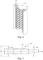
- Figures 2 and 3 illustrate an example of the central core 12 that can be used in the filter embodiment of Figure 1 .
- the end or top of central core 12 has an elongated shape that includes a convex curved central portion 18 and first and second end portions 20, 22.
- the core 12 may be centered about a central longitudinal axis 24 or may be at least slightly offset from the central axis 24.
- the core 12 also may be symmetric about the central axis 24, as shown, or the two portions on opposite sides of the central axis 24 can have at least a slightly different shape from each other.
- the core 12 is symmetric about the central axis 24.
- the first and second end portions 20, 22 have the same width 28, which is less than a maximum width 26 of the curved central portion 18.
- the end portions 20, 22 can instead have widths that are at least slightly different from each other.
- the curve of the central portion 18 of the core 12 is generally constant such that the width of the core 12 tapers generally constantly from the width 26 at the central area of the core to the width 28 at the first and second ends 20, 22.
- the curve of the central portion 18 can instead vary such that the radius of the curve varies across the length of the core 12.
- the ends 20, 22 are shown as being generally flat, with end surfaces that are generally perpendicular to the length of the core, although the end surfaces can be differently configured, such as curved, angled, or the like.
- Figures 2 and 3 illustrate one exemplary structural configuration for the central core 12 along its height, which includes a number of support structures.
- support structures can vary considerably, they are to be selected to provide sufficient structural integrity to the core while allowing for a desired flow volume through the core during filtration (i.e., designed such that the material flow is not significantly obstructed).
- the support structures illustrated extend both longitudinally and laterally, with spacing that provides for a desired filtration performance.
- the relative number of support structures can be higher or lower than illustrated. In any configuration, however, the outer perimeter of the core should have surfaces that provide structure against which pleat tips of the filter material can be supported.
- a single central core 12 extends along the entire height of the cylindrical filter 10. In other embodiments, the core 12 extends along only a portion of the height of the cylindrical filter 10. In configurations where the core 12 extends along only a portion of the height of the filter 10, it is possible that multiple cores 12 are "stacked" on each other along the height of the filter 10, either with or without spaces between them.
- This oval-like cross-sectional shape of the central core 12 helps to naturally space the pleats from each other around the periphery of the filter 10 while allowing more media to be fit into the space than with a central core that is circular. This is due to the geometry of a circular central core where spacing the inner tips adjacent the core with a desired spacing between them provides for relatively large spacing of the outer tips from each other, thereby not maximizing the amount of filter material that can be fit into the available space.
- the pleated filter material can be selected from a number of different materials, such as a non-woven material sheet (e.g., melt blown material) or micro porous membranes (e.g., nylon, poly(tetrafluoroethylene) (PTFE), polypropylene, polyethylene, and the like).
- a non-woven material sheet e.g., melt blown material
- micro porous membranes e.g., nylon, poly(tetrafluoroethylene) (PTFE), polypropylene, polyethylene, and the like.
- the pleated filter material can be provided as a sheet that is foldable multiple times to create the desired pattern and therefore is provided with a thickness that will allow it to fold back on itself and maintain the folded pattern.
- pleat refers generally to the V-shaped configurations of filter material that include two adjacent arms with distal ends that meet at an outer periphery of the cylindrical filter at a "peak". Each of those arms also includes a proximal end that is spaced radially inward from the outer periphery to define a portion of a V-shaped configuration internal to the outer filter periphery at a "valley.” Further, while a V-shape is described, the tip or point of the V-shape can be at least slightly rounded, where the radius of the tip is a function of the pleating method and tools used, along with the thickness of the filter material.
- the parameters of the central core 12 can be designed and adjusted accordingly. That is, the core dimensions can be selected to provide a cross-section that is more oval, circular, or rectangular than shown.
- Figure 4 provides for a filter 110 with a central core 112 that has first and second ends 120, 122 that are more rounded than the central core 12 of Figures 1-3 , and which has an overall more "flattened" shape.
- the filter material 114 is arranged so that its inner tips are adjacent the central core 112 along its longitudinal curved surfaces, but no inner tips are positioned directly adjacent to the tips of the first and second ends 120, 122.
- Filter 310 includes a central core 312 that extends along at least a portion of the height of the filter 310.
- Filter 310 further includes pleated filter material 314 arranged around the central core 312.
- the filter 310 has an outer peripheral boundary represented by the circle 316, which may be provided by a shell that extends along at least a portion of the filter height, filter caps at one or both ends of the filter material, and/or other structure.
- the outer peripheral boundary 316 is generally circular and designed or selected to fit into new and existing applications that utilize filters of this size and shape.
- the curve of the central portion 318 of the core 312 is generally constant such that the width of the core 312 tapers generally constantly from the width at the center of the core to the width at the first and second ends 320, 322. However, it is understood that the curve of the central portion 318 can instead vary such that the radius of the curve varies across the length of the core 312.
- the extending portions 330, 332 are shown as relatively pointed members that are identically sized and shaped. However, these extending portions 330, 332 can instead have a different shape and relative size than shown and can have different configurations (e.g., shape, size, and the like) from each other.
- the filter material 314 is arranged so that its inner tips are adjacent the central core 312 along its longitudinal curved surfaces, but no inner tips are positioned adjacent to the first and second ends 320, 322 or the extending portions 330, 332. That is, the pleats in this embodiment do not extend directly radially outward from an edge of the first and second ends 320, 322 in a direction that is generally perpendicular to the width of the curved central portion 318. Instead, the pleats at the area of the extending portions 330, 332 generally surround the shape of the extending portions 330, 332 and extend toward an outer peripheral boundary 316 of the filter 310. That is, filter material 314 generally follows an outer contour of each of the extending portions 330, 332, as shown.
- each of the cores is at least partially defined by an outer curved surface of its central portion.
- This outer curved surface generally has a radial curve that is flatter than a radial curve of the outer peripheral boundary of the cylindrical filter.
- the core is more "flattened” in shape as compared to the larger curve of outer peripheral boundary of the filter.
- the central core can be elliptical while the outer peripheral bounder can be circular or cylindrical, as is described herein relative to exemplary embodiments of the filter elements of the invention.
- a cylindrical filter element comprises a central longitudinal axis extending along a height of the filter element, a core element extending along at least a portion of the height of the filter element, the core element comprising a convex curved central portion extending from a first end to a second end to define a width of the core element, wherein the convex curved central portion comprises a maximum height through the central longitudinal axis that is larger than a height of at least one of the first and second ends, and filter material comprising a plurality of pleats extending radially from an outer periphery of the core element, wherein an outer cylindrical periphery of the filter material is defined by an outer pleat tip of each of the plurality of radially extending pleats, and wherein an inner pleat tip of each of the radially extending pleats is adjacent to the core element.
- the first and second ends of the core element have the same height; at least one inner pleat tip is adjacent to one of the first and second ends of the central portion of the core element; an area adjacent at least one of the first and second ends does not comprise any radially extending pleats; the core element further comprises a wing portion extending from at least one of the first and second ends, and wherein at least one of the wing portions comprises a height that is greater than the height of at least one of the first and second ends; the pleat depth of the plurality of pleats varies across the width of the core element such that each pleat increases in depth from the first end in the direction of the central longitudinal axis and then decreases in depth from a pleat adjacent to the central longitudinal axis in the direction of the second end; the core element is symmetrical or not symmetrical about the central longitudinal axis; the core element is offset from the central longitudinal axis; and/or the convex curved central portion of the core element
Landscapes
- Chemical & Material Sciences (AREA)
- Chemical Kinetics & Catalysis (AREA)
- Physics & Mathematics (AREA)
- Geometry (AREA)
- Filtering Of Dispersed Particles In Gases (AREA)
- Filtration Of Liquid (AREA)
- Filtering Materials (AREA)
Priority Applications (1)
| Application Number | Priority Date | Filing Date | Title |
|---|---|---|---|
| EP25169945.0A EP4596083A3 (en) | 2019-05-29 | 2020-05-26 | Curved core for variable pleat filter |
Applications Claiming Priority (3)
| Application Number | Priority Date | Filing Date | Title |
|---|---|---|---|
| US201962853935P | 2019-05-29 | 2019-05-29 | |
| EP20732426.0A EP3976225B1 (en) | 2019-05-29 | 2020-05-26 | Curved core for variable pleat filter |
| PCT/US2020/034526 WO2020243080A1 (en) | 2019-05-29 | 2020-05-26 | Curved core for variable pleat filter |
Related Parent Applications (1)
| Application Number | Title | Priority Date | Filing Date |
|---|---|---|---|
| EP20732426.0A Division EP3976225B1 (en) | 2019-05-29 | 2020-05-26 | Curved core for variable pleat filter |
Related Child Applications (1)
| Application Number | Title | Priority Date | Filing Date |
|---|---|---|---|
| EP25169945.0A Division EP4596083A3 (en) | 2019-05-29 | 2020-05-26 | Curved core for variable pleat filter |
Publications (4)
| Publication Number | Publication Date |
|---|---|
| EP4342568A2 EP4342568A2 (en) | 2024-03-27 |
| EP4342568A3 EP4342568A3 (en) | 2024-04-03 |
| EP4342568B1 true EP4342568B1 (en) | 2025-04-16 |
| EP4342568C0 EP4342568C0 (en) | 2025-04-16 |
Family
ID=71083765
Family Applications (3)
| Application Number | Title | Priority Date | Filing Date |
|---|---|---|---|
| EP23213581.4A Active EP4342568B1 (en) | 2019-05-29 | 2020-05-26 | Curved core for variable pleat filter |
| EP20732426.0A Active EP3976225B1 (en) | 2019-05-29 | 2020-05-26 | Curved core for variable pleat filter |
| EP25169945.0A Pending EP4596083A3 (en) | 2019-05-29 | 2020-05-26 | Curved core for variable pleat filter |
Family Applications After (2)
| Application Number | Title | Priority Date | Filing Date |
|---|---|---|---|
| EP20732426.0A Active EP3976225B1 (en) | 2019-05-29 | 2020-05-26 | Curved core for variable pleat filter |
| EP25169945.0A Pending EP4596083A3 (en) | 2019-05-29 | 2020-05-26 | Curved core for variable pleat filter |
Country Status (7)
| Country | Link |
|---|---|
| US (1) | US12558645B2 (https=) |
| EP (3) | EP4342568B1 (https=) |
| JP (2) | JP7617024B2 (https=) |
| KR (1) | KR20220015434A (https=) |
| CN (2) | CN118718589A (https=) |
| BR (1) | BR112021023916A2 (https=) |
| WO (1) | WO2020243080A1 (https=) |
Families Citing this family (1)
| Publication number | Priority date | Publication date | Assignee | Title |
|---|---|---|---|---|
| EP4263016B1 (en) * | 2020-12-17 | 2025-06-25 | Donaldson Company, Inc. | End caps and pleat guides for filtration |
Family Cites Families (26)
| Publication number | Priority date | Publication date | Assignee | Title |
|---|---|---|---|---|
| GB480810A (en) * | 1936-10-29 | 1938-03-01 | James Francois Emile Basset | Improvements in fluid purification and filtration devices |
| JPS58151411A (ja) | 1982-03-04 | 1983-09-08 | Kobe Steel Ltd | 転炉吹錬方法 |
| JPS6039044Y2 (ja) * | 1982-04-05 | 1985-11-22 | 眞 伊原 | ドライクリ−ニングにおける洗浄液などの清浄装置 |
| US5512076A (en) * | 1990-07-14 | 1996-04-30 | Gibson; Glenville | Filter apparatus |
| JPH0747093B2 (ja) * | 1991-04-27 | 1995-05-24 | 義見 忍足 | フィルター部材 |
| JPH0725908A (ja) | 1993-07-07 | 1995-01-27 | Showa Highpolymer Co Ltd | 連続重合方法および装置 |
| JPH0725908U (ja) * | 1993-10-18 | 1995-05-16 | 東京キユノ販売株式会社 | フィルタエレメント |
| US5730766A (en) * | 1996-11-05 | 1998-03-24 | Bha Group, Inc. | Non-round unitary filter cartridge |
| DE19756247A1 (de) | 1997-12-17 | 1999-06-24 | Bosch Gmbh Robert | Luftfilter |
| US20030029788A1 (en) * | 2000-02-23 | 2003-02-13 | Geert Denys | Pleated filter element |
| AU2001271698B2 (en) | 2000-06-30 | 2005-08-18 | Donaldson Company, Inc. | Air filter assembly for filtering air having particulate matter |
| US7648546B2 (en) * | 2006-01-06 | 2010-01-19 | Cummins Filtration Ip Inc. | Filter with variable pleat depth |
| US10040020B2 (en) | 2006-12-06 | 2018-08-07 | Baldwin Filters, Inc. | Fluid filter apparatus having filter media wound about a winding frame |
| DE202009000969U1 (de) * | 2009-01-26 | 2010-07-01 | Mann+Hummel Gmbh | Filterelement |
| US8051989B1 (en) * | 2009-05-11 | 2011-11-08 | Davco Technology, Llc | Support structure for a filter |
| WO2011034842A1 (en) | 2009-09-15 | 2011-03-24 | Purolator Filters Na Llc | Filter with main and supplemental filter elements and optional bubble breaker |
| DE102010045500A1 (de) * | 2010-09-15 | 2012-03-15 | Rt-Filtertechnik Gmbh | Filterflächenteil |
| DE102011077715A1 (de) * | 2011-06-17 | 2012-12-20 | Mahle International Gmbh | Filterelement und Filtereinrichtung |
| CN202538551U (zh) * | 2012-03-12 | 2012-11-21 | 江阴市人和环保设备有限公司 | 一种空气滤清器滤芯 |
| CN105658303B (zh) * | 2013-10-24 | 2018-01-26 | 唐纳森公司 | 用于褶状过滤介质的支撑结构和方法 |
| JP5811162B2 (ja) * | 2013-12-09 | 2015-11-11 | 住友電気工業株式会社 | プリーツフィルター、それを用いたバラスト水処理装置およびバラスト水の処理方法 |
| WO2015177282A1 (de) | 2014-05-21 | 2015-11-26 | Mann+Hummel Gmbh | Filtereinsatzteil mit einem gefalteten filterelement |
| DE102016003455B4 (de) | 2015-04-10 | 2020-08-06 | Mann+Hummel Gmbh | Filteraufnahme und Filteranordnung |
| DE102015004641A1 (de) | 2015-04-15 | 2016-10-20 | Mann + Hummel Gmbh | Filterelement, insbesondere zur Gasfiltration |
| EP3423166B1 (en) | 2016-03-02 | 2020-01-01 | Donaldson Company, Inc. | Filter element having inner support and method of filtering |
| US10918978B2 (en) | 2018-05-08 | 2021-02-16 | Cummins Filtration Ip, Inc. | Oval filter with exterior elliptical radial seal and internal support structure |
-
2020
- 2020-05-26 CN CN202410824717.1A patent/CN118718589A/zh active Pending
- 2020-05-26 US US17/614,175 patent/US12558645B2/en active Active
- 2020-05-26 JP JP2021564391A patent/JP7617024B2/ja active Active
- 2020-05-26 EP EP23213581.4A patent/EP4342568B1/en active Active
- 2020-05-26 EP EP20732426.0A patent/EP3976225B1/en active Active
- 2020-05-26 KR KR1020217042465A patent/KR20220015434A/ko active Pending
- 2020-05-26 EP EP25169945.0A patent/EP4596083A3/en active Pending
- 2020-05-26 BR BR112021023916A patent/BR112021023916A2/pt active Search and Examination
- 2020-05-26 CN CN202080038516.9A patent/CN113905800B/zh active Active
- 2020-05-26 WO PCT/US2020/034526 patent/WO2020243080A1/en not_active Ceased
-
2025
- 2025-01-06 JP JP2025001835A patent/JP2025063119A/ja active Pending
Also Published As
| Publication number | Publication date |
|---|---|
| EP3976225B1 (en) | 2023-12-06 |
| EP4342568A3 (en) | 2024-04-03 |
| JP7617024B2 (ja) | 2025-01-17 |
| EP4342568A2 (en) | 2024-03-27 |
| WO2020243080A1 (en) | 2020-12-03 |
| US12558645B2 (en) | 2026-02-24 |
| US20220323896A1 (en) | 2022-10-13 |
| CN118718589A (zh) | 2024-10-01 |
| BR112021023916A2 (pt) | 2022-01-25 |
| JP2025063119A (ja) | 2025-04-15 |
| JP2022534473A (ja) | 2022-08-01 |
| EP4596083A2 (en) | 2025-08-06 |
| EP3976225A1 (en) | 2022-04-06 |
| CN113905800A (zh) | 2022-01-07 |
| EP4596083A3 (en) | 2025-08-13 |
| KR20220015434A (ko) | 2022-02-08 |
| CN113905800B (zh) | 2024-07-26 |
| EP4342568C0 (en) | 2025-04-16 |
Similar Documents
| Publication | Publication Date | Title |
|---|---|---|
| US7311747B2 (en) | Filter assembly with pleated media V-packs, and methods | |
| EP3723890B1 (en) | Periodic radial symmetry for filter pleating | |
| EP2906320B1 (en) | Self-supporting folded sheet material, filter elements | |
| US4615804A (en) | High density pleat spacing and scoring tool and filter made therewith | |
| KR20150131229A (ko) | 난형의 관형 필터 카트리지 및 이를 이용한 필터 시스템 | |
| EP4342568B1 (en) | Curved core for variable pleat filter | |
| CN114423508B (zh) | 管状的褶折式过滤器部件 | |
| CN111085019A (zh) | 支撑和排放材料、过滤器和使用方法 | |
| CN111085025B (zh) | 支撑和排泄物料、过滤器和使用方法 | |
| CA3083638C (en) | Periodic radial symmetry for filter pleating | |
| BR112020011634B1 (pt) | Elemento filtrante cilíndrico |
Legal Events
| Date | Code | Title | Description |
|---|---|---|---|
| PUAI | Public reference made under article 153(3) epc to a published international application that has entered the european phase |
Free format text: ORIGINAL CODE: 0009012 |
|
| STAA | Information on the status of an ep patent application or granted ep patent |
Free format text: STATUS: THE APPLICATION HAS BEEN PUBLISHED |
|
| REG | Reference to a national code |
Ref country code: DE Ipc: B01D0046240000 Ref country code: DE Ref legal event code: R079 Ref document number: 602020049790 Country of ref document: DE Free format text: PREVIOUS MAIN CLASS: B01D0046520000 Ipc: B01D0046240000 |
|
| PUAL | Search report despatched |
Free format text: ORIGINAL CODE: 0009013 |
|
| AC | Divisional application: reference to earlier application |
Ref document number: 3976225 Country of ref document: EP Kind code of ref document: P |
|
| AK | Designated contracting states |
Kind code of ref document: A2 Designated state(s): AL AT BE BG CH CY CZ DE DK EE ES FI FR GB GR HR HU IE IS IT LI LT LU LV MC MK MT NL NO PL PT RO RS SE SI SK SM TR |
|
| AK | Designated contracting states |
Kind code of ref document: A3 Designated state(s): AL AT BE BG CH CY CZ DE DK EE ES FI FR GB GR HR HU IE IS IT LI LT LU LV MC MK MT NL NO PL PT RO RS SE SI SK SM TR |
|
| RIC1 | Information provided on ipc code assigned before grant |
Ipc: B01D 46/52 20060101ALI20240228BHEP Ipc: B01D 46/24 20060101AFI20240228BHEP |
|
| STAA | Information on the status of an ep patent application or granted ep patent |
Free format text: STATUS: REQUEST FOR EXAMINATION WAS MADE |
|
| 17P | Request for examination filed |
Effective date: 20240916 |
|
| RBV | Designated contracting states (corrected) |
Designated state(s): AL AT BE BG CH CY CZ DE DK EE ES FI FR GB GR HR HU IE IS IT LI LT LU LV MC MK MT NL NO PL PT RO RS SE SI SK SM TR |
|
| GRAP | Despatch of communication of intention to grant a patent |
Free format text: ORIGINAL CODE: EPIDOSNIGR1 |
|
| STAA | Information on the status of an ep patent application or granted ep patent |
Free format text: STATUS: GRANT OF PATENT IS INTENDED |
|
| INTG | Intention to grant announced |
Effective date: 20250102 |
|
| GRAS | Grant fee paid |
Free format text: ORIGINAL CODE: EPIDOSNIGR3 |
|
| GRAA | (expected) grant |
Free format text: ORIGINAL CODE: 0009210 |
|
| STAA | Information on the status of an ep patent application or granted ep patent |
Free format text: STATUS: THE PATENT HAS BEEN GRANTED |
|
| AC | Divisional application: reference to earlier application |
Ref document number: 3976225 Country of ref document: EP Kind code of ref document: P |
|
| AK | Designated contracting states |
Kind code of ref document: B1 Designated state(s): AL AT BE BG CH CY CZ DE DK EE ES FI FR GB GR HR HU IE IS IT LI LT LU LV MC MK MT NL NO PL PT RO RS SE SI SK SM TR |
|
| REG | Reference to a national code |
Ref country code: GB Ref legal event code: FG4D |
|
| REG | Reference to a national code |
Ref country code: CH Ref legal event code: EP |
|
| REG | Reference to a national code |
Ref country code: IE Ref legal event code: FG4D |
|
| REG | Reference to a national code |
Ref country code: DE Ref legal event code: R096 Ref document number: 602020049790 Country of ref document: DE |
|
| U01 | Request for unitary effect filed |
Effective date: 20250424 |
|
| U07 | Unitary effect registered |
Designated state(s): AT BE BG DE DK EE FI FR IT LT LU LV MT NL PT RO SE SI Effective date: 20250430 |
|
| U20 | Renewal fee for the european patent with unitary effect paid |
Year of fee payment: 6 Effective date: 20250430 |
|
| PGFP | Annual fee paid to national office [announced via postgrant information from national office to epo] |
Ref country code: GB Payment date: 20250520 Year of fee payment: 6 |
|
| PG25 | Lapsed in a contracting state [announced via postgrant information from national office to epo] |
Ref country code: ES Free format text: LAPSE BECAUSE OF FAILURE TO SUBMIT A TRANSLATION OF THE DESCRIPTION OR TO PAY THE FEE WITHIN THE PRESCRIBED TIME-LIMIT Effective date: 20250416 |
|
| PG25 | Lapsed in a contracting state [announced via postgrant information from national office to epo] |
Ref country code: GR Free format text: LAPSE BECAUSE OF FAILURE TO SUBMIT A TRANSLATION OF THE DESCRIPTION OR TO PAY THE FEE WITHIN THE PRESCRIBED TIME-LIMIT Effective date: 20250717 Ref country code: NO Free format text: LAPSE BECAUSE OF FAILURE TO SUBMIT A TRANSLATION OF THE DESCRIPTION OR TO PAY THE FEE WITHIN THE PRESCRIBED TIME-LIMIT Effective date: 20250716 |
|
| PG25 | Lapsed in a contracting state [announced via postgrant information from national office to epo] |
Ref country code: PL Free format text: LAPSE BECAUSE OF FAILURE TO SUBMIT A TRANSLATION OF THE DESCRIPTION OR TO PAY THE FEE WITHIN THE PRESCRIBED TIME-LIMIT Effective date: 20250416 |
|
| PG25 | Lapsed in a contracting state [announced via postgrant information from national office to epo] |
Ref country code: HR Free format text: LAPSE BECAUSE OF FAILURE TO SUBMIT A TRANSLATION OF THE DESCRIPTION OR TO PAY THE FEE WITHIN THE PRESCRIBED TIME-LIMIT Effective date: 20250416 |
|
| PG25 | Lapsed in a contracting state [announced via postgrant information from national office to epo] |
Ref country code: RS Free format text: LAPSE BECAUSE OF FAILURE TO SUBMIT A TRANSLATION OF THE DESCRIPTION OR TO PAY THE FEE WITHIN THE PRESCRIBED TIME-LIMIT Effective date: 20250716 |
|
| PG25 | Lapsed in a contracting state [announced via postgrant information from national office to epo] |
Ref country code: IS Free format text: LAPSE BECAUSE OF FAILURE TO SUBMIT A TRANSLATION OF THE DESCRIPTION OR TO PAY THE FEE WITHIN THE PRESCRIBED TIME-LIMIT Effective date: 20250816 |
|
| REG | Reference to a national code |
Ref country code: CH Ref legal event code: H13 Free format text: ST27 STATUS EVENT CODE: U-0-0-H10-H13 (AS PROVIDED BY THE NATIONAL OFFICE) Effective date: 20251223 |
|
| PG25 | Lapsed in a contracting state [announced via postgrant information from national office to epo] |
Ref country code: SM Free format text: LAPSE BECAUSE OF FAILURE TO SUBMIT A TRANSLATION OF THE DESCRIPTION OR TO PAY THE FEE WITHIN THE PRESCRIBED TIME-LIMIT Effective date: 20250416 |
|
| PG25 | Lapsed in a contracting state [announced via postgrant information from national office to epo] |
Ref country code: CH Free format text: LAPSE BECAUSE OF NON-PAYMENT OF DUE FEES Effective date: 20250531 |
|
| PG25 | Lapsed in a contracting state [announced via postgrant information from national office to epo] |
Ref country code: CZ Free format text: LAPSE BECAUSE OF FAILURE TO SUBMIT A TRANSLATION OF THE DESCRIPTION OR TO PAY THE FEE WITHIN THE PRESCRIBED TIME-LIMIT Effective date: 20250416 |
|
| PG25 | Lapsed in a contracting state [announced via postgrant information from national office to epo] |
Ref country code: SK Free format text: LAPSE BECAUSE OF FAILURE TO SUBMIT A TRANSLATION OF THE DESCRIPTION OR TO PAY THE FEE WITHIN THE PRESCRIBED TIME-LIMIT Effective date: 20250416 |
|
| PG25 | Lapsed in a contracting state [announced via postgrant information from national office to epo] |
Ref country code: MC Free format text: LAPSE BECAUSE OF FAILURE TO SUBMIT A TRANSLATION OF THE DESCRIPTION OR TO PAY THE FEE WITHIN THE PRESCRIBED TIME-LIMIT Effective date: 20250416 |
|
| PLBE | No opposition filed within time limit |
Free format text: ORIGINAL CODE: 0009261 |
|
| STAA | Information on the status of an ep patent application or granted ep patent |
Free format text: STATUS: NO OPPOSITION FILED WITHIN TIME LIMIT |
|
| REG | Reference to a national code |
Ref country code: CH Ref legal event code: L10 Free format text: ST27 STATUS EVENT CODE: U-0-0-L10-L00 (AS PROVIDED BY THE NATIONAL OFFICE) Effective date: 20260225 |
|
| 26N | No opposition filed |
Effective date: 20260119 |
|
| PG25 | Lapsed in a contracting state [announced via postgrant information from national office to epo] |
Ref country code: IE Free format text: LAPSE BECAUSE OF NON-PAYMENT OF DUE FEES Effective date: 20250526 |