EP4339709A2 - Heizvorrichtung, fixiervorrichtung und bilderzeugungsvorrichtung - Google Patents
Heizvorrichtung, fixiervorrichtung und bilderzeugungsvorrichtung Download PDFInfo
- Publication number
- EP4339709A2 EP4339709A2 EP23218622.1A EP23218622A EP4339709A2 EP 4339709 A2 EP4339709 A2 EP 4339709A2 EP 23218622 A EP23218622 A EP 23218622A EP 4339709 A2 EP4339709 A2 EP 4339709A2
- Authority
- EP
- European Patent Office
- Prior art keywords
- resistance heating
- temperature
- heating elements
- heating element
- fixing
- Prior art date
- Legal status (The legal status is an assumption and is not a legal conclusion. Google has not performed a legal analysis and makes no representation as to the accuracy of the status listed.)
- Pending
Links
- 238000010438 heat treatment Methods 0.000 title claims abstract description 279
- 230000002093 peripheral effect Effects 0.000 claims description 3
- 238000001514 detection method Methods 0.000 abstract description 4
- 238000000034 method Methods 0.000 description 17
- 238000007639 printing Methods 0.000 description 15
- 230000008569 process Effects 0.000 description 15
- 239000000463 material Substances 0.000 description 13
- 238000000926 separation method Methods 0.000 description 11
- 238000004140 cleaning Methods 0.000 description 7
- 230000015572 biosynthetic process Effects 0.000 description 6
- 239000000843 powder Substances 0.000 description 6
- 239000003086 colorant Substances 0.000 description 5
- 239000011347 resin Substances 0.000 description 5
- 229920005989 resin Polymers 0.000 description 5
- 239000004642 Polyimide Substances 0.000 description 4
- 230000004048 modification Effects 0.000 description 4
- 238000012986 modification Methods 0.000 description 4
- 229920001721 polyimide Polymers 0.000 description 4
- PXHVJJICTQNCMI-UHFFFAOYSA-N Nickel Chemical compound [Ni] PXHVJJICTQNCMI-UHFFFAOYSA-N 0.000 description 3
- 230000007423 decrease Effects 0.000 description 3
- 230000006870 function Effects 0.000 description 3
- 239000011521 glass Substances 0.000 description 3
- 229920001343 polytetrafluoroethylene Polymers 0.000 description 3
- 239000004810 polytetrafluoroethylene Substances 0.000 description 3
- 239000002699 waste material Substances 0.000 description 3
- OKTJSMMVPCPJKN-UHFFFAOYSA-N Carbon Chemical compound [C] OKTJSMMVPCPJKN-UHFFFAOYSA-N 0.000 description 2
- YCKRFDGAMUMZLT-UHFFFAOYSA-N Fluorine atom Chemical compound [F] YCKRFDGAMUMZLT-UHFFFAOYSA-N 0.000 description 2
- XEEYBQQBJWHFJM-UHFFFAOYSA-N Iron Chemical compound [Fe] XEEYBQQBJWHFJM-UHFFFAOYSA-N 0.000 description 2
- 229920000106 Liquid crystal polymer Polymers 0.000 description 2
- 239000004977 Liquid-crystal polymers (LCPs) Substances 0.000 description 2
- 239000004813 Perfluoroalkoxy alkane Substances 0.000 description 2
- 239000004696 Poly ether ether ketone Substances 0.000 description 2
- PNEYBMLMFCGWSK-UHFFFAOYSA-N aluminium oxide Inorganic materials [O-2].[O-2].[O-2].[Al+3].[Al+3] PNEYBMLMFCGWSK-UHFFFAOYSA-N 0.000 description 2
- PMHQVHHXPFUNSP-UHFFFAOYSA-M copper(1+);methylsulfanylmethane;bromide Chemical compound Br[Cu].CSC PMHQVHHXPFUNSP-UHFFFAOYSA-M 0.000 description 2
- 238000010586 diagram Methods 0.000 description 2
- 238000007599 discharging Methods 0.000 description 2
- 239000011737 fluorine Substances 0.000 description 2
- 229910052731 fluorine Inorganic materials 0.000 description 2
- 230000017525 heat dissipation Effects 0.000 description 2
- 230000020169 heat generation Effects 0.000 description 2
- SWELZOZIOHGSPA-UHFFFAOYSA-N palladium silver Chemical compound [Pd].[Ag] SWELZOZIOHGSPA-UHFFFAOYSA-N 0.000 description 2
- 229920011301 perfluoro alkoxyl alkane Polymers 0.000 description 2
- 229920002530 polyetherether ketone Polymers 0.000 description 2
- 238000007650 screen-printing Methods 0.000 description 2
- 239000010935 stainless steel Substances 0.000 description 2
- 229910001220 stainless steel Inorganic materials 0.000 description 2
- 238000011144 upstream manufacturing Methods 0.000 description 2
- 229910001316 Ag alloy Inorganic materials 0.000 description 1
- 229920000049 Carbon (fiber) Polymers 0.000 description 1
- RYGMFSIKBFXOCR-UHFFFAOYSA-N Copper Chemical compound [Cu] RYGMFSIKBFXOCR-UHFFFAOYSA-N 0.000 description 1
- 101100434911 Mus musculus Angpt1 gene Proteins 0.000 description 1
- BQCADISMDOOEFD-UHFFFAOYSA-N Silver Chemical compound [Ag] BQCADISMDOOEFD-UHFFFAOYSA-N 0.000 description 1
- 230000004075 alteration Effects 0.000 description 1
- 229910052782 aluminium Inorganic materials 0.000 description 1
- XAGFODPZIPBFFR-UHFFFAOYSA-N aluminium Chemical compound [Al] XAGFODPZIPBFFR-UHFFFAOYSA-N 0.000 description 1
- 230000005540 biological transmission Effects 0.000 description 1
- 239000004917 carbon fiber Substances 0.000 description 1
- 239000000919 ceramic Substances 0.000 description 1
- 239000000470 constituent Substances 0.000 description 1
- 229910052802 copper Inorganic materials 0.000 description 1
- 239000010949 copper Substances 0.000 description 1
- 238000001035 drying Methods 0.000 description 1
- 229920001971 elastomer Polymers 0.000 description 1
- 238000004134 energy conservation Methods 0.000 description 1
- 239000004744 fabric Substances 0.000 description 1
- 230000002349 favourable effect Effects 0.000 description 1
- 238000010304 firing Methods 0.000 description 1
- 229910021389 graphene Inorganic materials 0.000 description 1
- 229910002804 graphite Inorganic materials 0.000 description 1
- 239000010439 graphite Substances 0.000 description 1
- 238000007689 inspection Methods 0.000 description 1
- 239000011810 insulating material Substances 0.000 description 1
- 238000009413 insulation Methods 0.000 description 1
- 229910052742 iron Inorganic materials 0.000 description 1
- 229910052751 metal Inorganic materials 0.000 description 1
- 239000002184 metal Substances 0.000 description 1
- 239000010445 mica Substances 0.000 description 1
- 229910052618 mica group Inorganic materials 0.000 description 1
- 229910052759 nickel Inorganic materials 0.000 description 1
- 239000002985 plastic film Substances 0.000 description 1
- 229920006255 plastic film Polymers 0.000 description 1
- -1 polytetrafluoroethylene Polymers 0.000 description 1
- 230000004044 response Effects 0.000 description 1
- 230000000717 retained effect Effects 0.000 description 1
- 230000000630 rising effect Effects 0.000 description 1
- WOCIAKWEIIZHES-UHFFFAOYSA-N ruthenium(iv) oxide Chemical compound O=[Ru]=O WOCIAKWEIIZHES-UHFFFAOYSA-N 0.000 description 1
- 229920002379 silicone rubber Polymers 0.000 description 1
- 239000004945 silicone rubber Substances 0.000 description 1
- 229910052709 silver Inorganic materials 0.000 description 1
- 239000004332 silver Substances 0.000 description 1
- 239000007787 solid Substances 0.000 description 1
Images


Classifications
-
- G—PHYSICS
- G03—PHOTOGRAPHY; CINEMATOGRAPHY; ANALOGOUS TECHNIQUES USING WAVES OTHER THAN OPTICAL WAVES; ELECTROGRAPHY; HOLOGRAPHY
- G03G—ELECTROGRAPHY; ELECTROPHOTOGRAPHY; MAGNETOGRAPHY
- G03G15/00—Apparatus for electrographic processes using a charge pattern
- G03G15/20—Apparatus for electrographic processes using a charge pattern for fixing, e.g. by using heat
- G03G15/2003—Apparatus for electrographic processes using a charge pattern for fixing, e.g. by using heat using heat
- G03G15/2014—Apparatus for electrographic processes using a charge pattern for fixing, e.g. by using heat using heat using contact heat
- G03G15/2053—Structural details of heat elements, e.g. structure of roller or belt, eddy current, induction heating
-
- G—PHYSICS
- G03—PHOTOGRAPHY; CINEMATOGRAPHY; ANALOGOUS TECHNIQUES USING WAVES OTHER THAN OPTICAL WAVES; ELECTROGRAPHY; HOLOGRAPHY
- G03G—ELECTROGRAPHY; ELECTROPHOTOGRAPHY; MAGNETOGRAPHY
- G03G15/00—Apparatus for electrographic processes using a charge pattern
- G03G15/20—Apparatus for electrographic processes using a charge pattern for fixing, e.g. by using heat
- G03G15/2003—Apparatus for electrographic processes using a charge pattern for fixing, e.g. by using heat using heat
- G03G15/2014—Apparatus for electrographic processes using a charge pattern for fixing, e.g. by using heat using heat using contact heat
- G03G15/2039—Apparatus for electrographic processes using a charge pattern for fixing, e.g. by using heat using heat using contact heat with means for controlling the fixing temperature
- G03G15/2042—Apparatus for electrographic processes using a charge pattern for fixing, e.g. by using heat using heat using contact heat with means for controlling the fixing temperature specially for the axial heat partition
-
- G—PHYSICS
- G03—PHOTOGRAPHY; CINEMATOGRAPHY; ANALOGOUS TECHNIQUES USING WAVES OTHER THAN OPTICAL WAVES; ELECTROGRAPHY; HOLOGRAPHY
- G03G—ELECTROGRAPHY; ELECTROPHOTOGRAPHY; MAGNETOGRAPHY
- G03G21/00—Arrangements not provided for by groups G03G13/00 - G03G19/00, e.g. cleaning, elimination of residual charge
-
- H—ELECTRICITY
- H05—ELECTRIC TECHNIQUES NOT OTHERWISE PROVIDED FOR
- H05B—ELECTRIC HEATING; ELECTRIC LIGHT SOURCES NOT OTHERWISE PROVIDED FOR; CIRCUIT ARRANGEMENTS FOR ELECTRIC LIGHT SOURCES, IN GENERAL
- H05B1/00—Details of electric heating devices
- H05B1/02—Automatic switching arrangements specially adapted to apparatus ; Control of heating devices
- H05B1/0227—Applications
- H05B1/023—Industrial applications
- H05B1/0241—For photocopiers
-
- G—PHYSICS
- G03—PHOTOGRAPHY; CINEMATOGRAPHY; ANALOGOUS TECHNIQUES USING WAVES OTHER THAN OPTICAL WAVES; ELECTROGRAPHY; HOLOGRAPHY
- G03G—ELECTROGRAPHY; ELECTROPHOTOGRAPHY; MAGNETOGRAPHY
- G03G2215/00—Apparatus for electrophotographic processes
- G03G2215/20—Details of the fixing device or porcess
- G03G2215/2003—Structural features of the fixing device
- G03G2215/2016—Heating belt
- G03G2215/2019—Heating belt the belt not heating the toner or medium directly, e.g. heating a heating roller
-
- G—PHYSICS
- G03—PHOTOGRAPHY; CINEMATOGRAPHY; ANALOGOUS TECHNIQUES USING WAVES OTHER THAN OPTICAL WAVES; ELECTROGRAPHY; HOLOGRAPHY
- G03G—ELECTROGRAPHY; ELECTROPHOTOGRAPHY; MAGNETOGRAPHY
- G03G2215/00—Apparatus for electrophotographic processes
- G03G2215/20—Details of the fixing device or porcess
- G03G2215/2003—Structural features of the fixing device
- G03G2215/2016—Heating belt
- G03G2215/2035—Heating belt the fixing nip having a stationary belt support member opposing a pressure member
Definitions
- the present disclosure relates to a heating device including a plurality of resistance heating elements, a fixing device, and an image forming apparatus.
- One type of fixing device heats a thin fixing belt having low heat capacity, with a planar heating body including a base and a resistance heating element.
- the planer heating body includes a plurality of resistance heating elements arranged on the base disposed in the width direction of the fixing belt, the resistance heating elements being electrically connected in parallel.
- This arrangement inhibits a rise in temperature in a no-paper passing portion when small-sized paper passes the planer heating body (refer to JP-2015-194713-A and JP-2016-18127-A ).
- PTC positive temperature coefficient
- the plurality of resistance heating elements is connected in parallel as described above, even when any one of the resistance heating elements disconnects, current continues to flow through the other resistance heating elements.
- a temperature sensor such as a thermistor, is arranged in the heating region of each resistance heating element, the temperatures of the resistance heating elements can be individually controlled. Thus, no unusual rise occurs in temperature in each resistance heating element.
- a temperature sensor is attached to only one resistance heating element at the center in the longitudinal direction.
- the resistance heating element disconnects, current continuously increases in the other resistance heating elements.
- a safety element such as a thermostat or a fuse, is arranged in the heating region of a resistance heating element as in FIG. 3C in JP-2015-194713-A , when the resistance heating element disconnects, the safety element does not function.
- an object of the present disclosure is to provide a heating device, a fixing device, and an image forming apparatus that are capable of performing temperature control to a plurality of resistance heating elements in a planar heating body with as few temperature sensors as possible, so as to prevent an unusual rise in temperature.
- a heating device includes a base; a plurality of resistance heating elements arranged in a longitudinal direction of the base and electrically connected in parallel to each other; a power controller configured to supply power to the plurality of resistance heating elements; a first temperature detector configured to detect a temperature of a first resistance heating element of the plurality of resistance heating elements; a second temperature detector configured to detect a temperature of a second resistance heating element of the plurality of resistance heating elements; a power interrupter configured to interrupt the power supplied from the power controller to the plurality of resistance heating elements when the temperature of the second resistance heating element becomes a predetermined temperature or more; and a controller configured to control the power controller such that a temperature of each of the plurality of resistance heating elements becomes a predetermined temperature, based on a result of detection of the first temperature detector, and to interrupt the power supplied from the power controller to the plurality of resistance heating elements when the second temperature detector detects predetermined temperature information regarding the second resistance heating element.
- the second temperature detector detects the predetermined temperature information regarding the second resistance heating element and then the power supply to each resistance heating element is interrupted.
- an unusual rise in temperature in each resistance heating element can be reliably prevented.
- a heating device according to an embodiment of the present disclosure, a fixing device using the heating device, and an image forming apparatus (laser printer) will be described below with reference to the drawings. Note that the same parts or similar parts are denoted with the same reference signs in the figures, and thus the duplicate descriptions of the parts will be simplified or omitted appropriately.
- the dimensions, material, shape, and relative position in a description for each constituent component are exemplary. Unless otherwise specifically described, the scope of the present disclosure is not limited to those.
- the “recording medium” is not limited to paper (sheet).
- the “recording medium” include not only paper (sheet) but also an overhead projector (OHP) sheet, a fabric, a metallic sheet, a plastic film, and a prepreg sheet including carbon fibers previously impregnated with resin.
- OHP overhead projector
- Examples of the "recording medium” include a medium to which developer or ink can adhere, and so-called recording paper and recording sheets.
- Examples of the "sheet” include thick paper, a postcard, an envelope, thin paper, coated paper (e.g., coat paper and art paper), and tracing paper, in addition to plain paper.
- Image formation to be used in the following descriptions means not only giving an image having a meaning, such as a character or a figure, to a medium but also giving an image having no meaning, such as a pattern, to a medium.
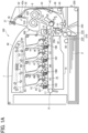
- FIG. 1A is a schematic view of the configuration of a color laser printer 100 that is an image forming apparatus including a heating device 3000 and a fixing device 300, according to one embodiment of the present disclosure.
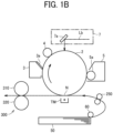
- FIG. 1B simplifies and illustrates the principle of the laser printer 100.
- the color laser printer 100 includes four process units 1K, 1Y, 1M, and 1C each serving as an image forming unit.
- the process units form an image with respective developers of black (K), yellow (Y), magenta (M), and cyan (C) in color corresponding to the color separation components of a color image.
- the process units 1K, 1Y, 1M, and 1C have similar configurations except including toner bottles 6K, 6Y, 6M, and 6C housing unused toners in mutually different colors.
- the configuration of the one process unit 1K will be described below, and the descriptions of the other process units 1Y, 1M, and 1C will be omitted.
- the process unit 1K includes an image bearer 2K (e.g., a photoconductor drum), a drum cleaning device 3K, and a discharging device.
- the process unit 1K further includes a charging device 4K serving as a charging unit that uniformly charges the surface of an image bearer and a developing device 5K serving as a developing unit that performs visible image processing to an electrostatic latent image on the image bearer.
- the process unit 1K is detachably attached to the body of the laser printer 100 and thus can be replaced simultaneously with a consumed component.
- An exposure device 7 is arranged above the process units 1K, 1Y, 1M, and 1C provided in the laser printer 100.
- the exposure device 7 performs writing scanning in accordance with image information, namely, causes a mirror 7a to reflect a laser beam Lb from a laser diode to irradiate the image bearer 2K with the laser beam Lb, on the basis of image data.
- a transfer device 15 is arranged below the process units 1K, 1Y, 1M, and 1C in the present embodiment.
- the transfer device 15 corresponds to a transfer unit TM of FIG. 1B .
- Primary transfer rollers 19K, 19Y, 19M, and 19C are disposed opposed to the image bearers 2K, 2Y, 2M, and 2C, respectively, abutting on an intermediate transfer belt 16.
- the intermediate transfer belt 16 that has been kept taut around the primary transfer rollers 19K, 19Y, 19M, and 19C, a driving roller 18, and a driven roller 17, circulates and travels.
- a secondary transfer roller 20 is disposed opposed to the driving roller 18, abutting on the intermediate transfer belt 16. Note that if the image bearers 2K, 2Y, 2M, and 2C are regarded as first image bearers for the colors, the intermediate transfer belt 16 is a second image bearer on which the respective images on the image bearers 2K, 2Y, 2M, and 2C are combined.
- a belt cleaning device 21 is provided on the downstream side with respect to the secondary transfer roller 20 in the traveling direction of the intermediate transfer belt 16.
- a cleaning backup roller is provided on the opposite side of the belt cleaning device 21 with respect to the intermediate transfer belt 16.
- the sheet feeding device 200 intended for a recording-medium supply device can house a sheaf of a large number of sheets P each serving as a recording medium.
- the sheet feeding device 200 is unitized together with a sheet feeding roller 60 and paired rollers 210 serving as a conveyor for the sheets P.
- the sheet feeding device 200 is detachably inserted in the body of the laser printer 100 for sheet supply.
- the sheet feeding roller 60 and the paired rollers 210 disposed above the sheet feeding device 200, convey the uppermost sheet P in the sheet feeding device 200 to a sheet feed path 32.
- Paired registration rollers 250 that serve as a separation conveyor and are disposed on the nearest upstream side in the conveyance direction of the secondary transfer roller 20, can temporarily stop the sheet P fed from the sheet feeding device 200.
- the temporary stop causes slack on the front end side of the sheet P, so that the oblique (skew) of the sheet P is modified.
- a conveyance roller 240 for conveying the sheet conveyed on the right side from the paired rollers 210, upward, is arranged at the downstream end of the sheet feeding device 200. As illustrated in FIG. 1A , the conveyance roller 240 conveys the sheet to the paired registration rollers 250 above.
- the paired rollers 210 include a pair of an upper roller and a lower roller.
- the paired rollers 210 can adopt a friction reverse roller (FRR) separation system or a friction roller (FR) separation system.
- the FRR separation system presses a separation roller (return roller) to which a driving shaft has applied a certain amount of torque in the counter sheet feeding direction through a torque limiter, against a feed roller to separate a sheet with the nip between the rollers.
- the FR separation system presses a separation roller (friction roller) supported by a secured shaft against a feed roller through a torque limiter to separate a sheet with the nip between the rollers.
- the paired rollers 210 in the present embodiment adopt the FRR separation system. That is the paired rollers 210 include an upside feed roller 220 that conveys a sheet inside the machine and a downside separation roller 230 that gives a driving force in the reverse direction of the upside feed roller 220 with a driving shaft through a torque limiter.
- the separation roller 230 is biased to the feed roller 220 by a biasing means, such as a spring. Note that transmission of the driving force of the feed roller 220 through a clutch, rotates the sheet feeding roller 60 left in FIG. 1A .
- the sent-out sheet P has the toner image on the intermediate transfer belt 16, electrostatically transferred at a desirable transfer position with high accuracy by a bias applied at the secondary transfer nip.
- a post-transfer conveyance path 33 is arranged above the secondary transfer nip between the secondary transfer roller 20 and the driving roller 18.
- the fixing device 300 is provided in proximity to the upper end of the post-transfer conveyance path 33.
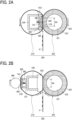
- the fixing device 300 includes: a fixing belt 310 enveloping the heating device 3000; and a pressing roller 320 serving as a pressing member that rotates while abutting on the fixing belt 310 with a predetermined pressure. Note that other configurations as in FIGS. 2B to 2D to be described later can be adopted as the fixing device 300.
- a post-fixing conveyance path 35 arranged above the fixing device 300 branches into a sheet ejection path 36 and a reverse conveyance path 41 at the upper end of the post-fixing conveyance path 35.
- Paired ejection rollers 37 are arranged in proximity to the opening end of a sheet ejection path 36.
- the reverse conveyance path 41 joins together with the sheet feed path 32, at the other end on the opposed side to the branch. Paired reverse conveyance rollers 43 are arranged midway through the reverse conveyance path 41.
- a powder container 10 (e.g., a toner container) is disposed between the transfer device 15 and the sheet feeding device 200.
- the powder container 10 is detachably attached to the body of the laser printer 100.
- the laser printer 100 needs a predetermined distance from the sheet feeding roller 60 to the secondary transfer roller 20.
- the powder container 10 is provided in dead space due to the distance, so that the entire laser printer is rendered in miniaturization.
- a transfer cover 8 is disposed on the front side in the drawing direction of the sheet feeding device 200 above the sheet feeding device 200. Opening the transfer cover 8 enables an internal inspection of the laser printer 100.
- the transfer cover 8 includes a manual sheet feeding roller 45 for manual sheet feeding and a manual sheet feeding tray 46 for manual sheet feeding.
- the laser printer according to the present embodiment is an exemplary image forming apparatus, and thus the image forming apparatus is not limited to the laser printer. That is the image forming apparatus can include any one of a copying machine, a facsimile, a printer, a printing machine, and an inkjet recording device or can include a multifunction peripheral having a combination of at least two of the copying machine, the facsimile, the printer, the printing machine, and the inkjet recording device.
- the sheet feeding roller 60 rotates due to a sheet feeding signal from a controller of the laser printer 100.
- the sheet feeding roller 60 separates the uppermost sheet from a sheaf of sheets P loaded in the sheet feeding device 200, and sends the uppermost sheet out to the sheet feed path 32.
- the sheet P sent out by the sheet feeding roller 60 and the paired rollers 210 has slack when the front end of the sheet P arrives at the nip between the paired registration rollers 250, and then remains on standby.
- An optimum timing of transferring the toner image on the intermediate transfer belt 16 to the sheet P (synchronization) is determined and additionally the front end skew of the sheet P is corrected.
- a sheaf of sheets loaded in the manual sheet feeding tray 46 one by one from the uppermost sheet passes through part of the reverse conveyance path 41 due to the manual sheet feeding roller 45, and then is conveyed to the nip between the paired registration rollers 250.
- the following operation is the same as the sheet feeding from the sheet feeding device 200.
- the charging device 4K charges the surface of the image bearer 2K uniformly at high potential.
- the exposure device 7 irradiates the surface of the image bearer 2K with the laser beam Lb on the basis of the image data.
- the surface of the image bearer 2K irradiated with the laser beam Lb has an electrostatic latent image due to a drop in the potential of the irradiated portion.
- the developing device 5K including a developer carrier carrying a developer including toner, transfers unused black toner supplied from the toner bottle 6K to the surface portion of the image bearer 2K having the electrostatic latent image, through the developer carrier.
- the image bearer 2K to which the toner has been transferred forms (develops) a black toner image on the surface of the image bearer 2K.
- the toner image on the image bearer 2K is transferred to the intermediate transfer belt 16.
- the drum cleaning device 3K removes the remaining toner adhering to the surface of the image bearer 2K after the intermediate transfer process.
- the removed remaining toner is sent to a waste toner container inside the process unit 1K by a waste toner conveyor and then is collected.
- the discharging device discharges the remaining charge of the image bearer 2K from which the remaining toner has been removed by the drum cleaning device 3K.
- toner images are formed on the image bearers 2Y, 2M, and 2C in the process units 1Y, 1M, and 1C for the colors, and the toner images in the colors are transferred to the intermediate transfer belt 16 such that the toner images are superimposed on each other.
- the intermediate transfer belt 16 having the toner images in the colors superimposed on each other travels to the secondary transfer nip between the secondary transfer roller 20 and the driving roller 18. Meanwhile, the paired registration rollers 250 nip a sheet thrust against the paired registration rollers 250 and rotate at a predetermined timing.
- the paired registration rollers 250 convey the sheet to the secondary transfer nip between the secondary transfer roller 20 and the driving roller 18 at a suitable timing of transferring the toner image on the intermediate transfer belt 16 due to the superimposition transfer. In this manner, the toner image on the intermediate transfer belt 16 is transferred to the sheet P sent out by the paired registration rollers 250.
- the sheet P to which the toner image has been transferred is conveyed to the fixing device 300 through the post-transfer conveyance path 33.
- the sheet P conveyed to the fixing device 300 is nipped by the fixing belt 310 and the pressing roller 320. Then, heating and pressing fixes the unfixed toner image to the sheet P.
- the sheet P to which the toner image has been fixed is sent out from the fixing device 300 to the post-fixing conveyance path 35.
- the switching member 42 is located opening in proximity to the upper end of the post-fixing conveyance path 35, as indicated with a solid line of FIG. 1A , in the timing at which the fixing device 300 sends out the sheet P.
- the sheet P sent out from the fixing device 300 is sent out to the sheet ejection path 36 through the post-fixing conveyance path 35.
- the paired ejection rollers 37 nip the sheet P sent out to the sheet ejection path 36 and drive rotationally to eject the sheet P to the ejection tray 44. Then, the single-sided printing finishes.
- the fixing device 300 sends out a sheet P to the sheet ejection path 36.
- the paired ejection rollers 37 drive rotationally to convey part of the sheet P outside the laser printer 100.
- the switching member 42 pivots on the pivot shaft 42a as indicated with a dotted line of FIG. 1A , to close the upper end of the post-fixing conveyance path 35.
- the paired ejection rollers 37 rotate in a direction reverse to the direction in which the sheet P is conveyed outside the laser printer 100, to send out the sheet P to the reverse conveyance path 41.
- the sheet P sent out to the reverse conveyance path 41 reaches the paired registration rollers 250 through the paired reverse conveyance rollers 43.
- the paired registration rollers 250 determine an optimum timing of transferring the toner image on the intermediate transfer belt 16 to the face of the sheet P to which no toner image has been transferred (synchronization), and send out the sheet P to the secondary transfer nip.
- the secondary transfer roller 20 and the driving roller 18 transfer the toner image to the face of the sheet P to which no toner image has been transferred (back face).
- the sheet P to which the toner image has been transferred is conveyed to the fixing device 300 through the post-transfer conveyance path 33.
- the fixing device 300 nips the conveyed sheet P with the fixing belt 310 and the pressing roller 320, and fixes the unfixed toner image to the back face of the sheet P with heating and pressing.
- the switching member 42 is located opening in proximity to the upper end of the post-fixing conveyance path 35, as indicated with the solid line of FIG. 1A , in the timing at which the fixing device 300 sends out the sheet P.
- the sheet P sent out from the fixing device 300 is sent out to the sheet ejection path 36 through the post-fixing conveyance path 35.
- the paired ejection rollers 37 nip the sheet P sent out to the sheet ejection path 36 and drive rotationally to eject the sheet P to the ejection tray 44. Then, the double-sided printing finishes.
- the belt cleaning device 21 removes the remaining toner from the intermediate transfer belt 16.
- the toner removed from the intermediate transfer belt 16 is conveyed to the powder container 10 by a waste toner conveyor and is collected inside the powder container 10.
- the heating device 3000 is intended for heating the fixing belt 310 of the fixing device 300.
- the heating device 3000 including a planar heating body includes: a base 350 including an elongate metallic thin member covered with an insulating material; and a heating member 360 arranged on the base 350.
- the heating member 360 includes a plurality of resistance heating elements 361 to 368 disposed straight at regular intervals in the longitudinal direction of the base 350.
- Power lines 360a and 360b each having a small resistance value are arranged straight mutually in parallel on both sides in the lateral direction of the resistance heating elements 361 to 368. Both ends of each of the resistance heating elements 361 to 368 are connected to the power lines 360a and 360b.
- a power controller is connected to electrodes 360c and 360d at respective one end portions of the power lines 360a and 360b.
- the heating device 3000 includes, as a temperature detector that detects the temperature of a resistance heating element, a first temperature sensor TH1 serving as a first temperature detector and a second temperature sensor TH2 serving as a second temperature detector.
- the temperature sensors TH1 and TH2 can each include, for example, a thermistor.
- the heating device 3000 includes a power cutoff device CO serving as a power interrupter that interrupts power supply to a resistance heating element when the temperature of the resistance heating element becomes unusually high.
- the power cutoff device CO can include a thermostat or a fuse.
- the first temperature sensor TH1, the second temperature sensor TH2, and the power cutoff device CO are each arranged crimped with a spring to the back side of the base 350.
- the first temperature sensor TH1 is intended for temperature control
- the second temperature sensor TH2 is intended for safety protection.
- the two temperature sensors TH1 and TH2 can each include a contact thermistor having a thermal time constant of less than one second.
- the first temperature sensor TH1 for temperature control is disposed in the heating region of the resistance heating element 364 (the fourth from the left end) serving as a first resistance heating element in a central region in the longitudinal direction within a minimum paper passing width.
- the second temperature sensor TH2 for safety protection and the power cutoff device CO are disposed in the heating region of the resistance heating element 368 (the eighth from the left end) (or the resistance heating element 361 (the first from the left end)) serving as a second resistance heating element at a farthest end portion in the longitudinal direction at which an extreme rise is more likely to occur in end-portion temperature.
- the second temperature sensor TH2 and the power cutoff device CO can be arranged in the heating region of at least one of the other resistance heating elements 361 to 367.
- the two temperature sensors TH1 and TH2 and the power cutoff device CO are disposed in the regions of the resistance heating elements 364 and 368 such that the gap between resistance heating elements at which a drop occurs in the amount of heat generation is avoided. This arrangement improves temperature controllability, and also facilitates disconnection detection in a case where disconnection occurs in part of the resistance heating elements.
- the first temperature sensor TH1 may be disposed in the heating region of any of the resistance heating elements 363, 365, and 366.
- the second temperature sensor TH2 and the power cutoff device CO can be disposed in the heating region of the resistance heating element 362 that is the second from the left end or in the heating region of the resistance heating element 367 that is the seventh from the left end.
- the second temperature sensor TH2 and the power cutoff device CO are not necessarily disposed at a farthest end portion in the longitudinal direction.
- the power control circuit includes an alternating-current power source 410, a triac 420, and the power cutoff device CO.
- the alternating-current power source 410, the triac 420, and the power cutoff device CO are connected in series between the electrodes 360c and 360d.
- FIGS. 5A and 5B each illustrate an exemplary configuration of the power cutoff device CO.
- the power cutoff device CO includes a body case 500, a first terminal 501, a connector 502, a second terminal 503, an ejecting rod 504 secured on the lower face of the connector 502, and a bowl-shaped bimetal 505 disposed on the bottom of the body case 500.
- the connector 502 has a base end supported by the first terminal 501.
- the connector 502 is biased downward due to the elasticity of the connector 502.
- the ejecting rod 504 couples the connector 502 and the central upper face of the bimetal 505 together.
- the bimetal 505 inverts in an upward convex shape as in FIG. 5B due to a predetermined high temperature, the ejecting rod 504 pushes the connector 502 upward, so that an interruption is made between the first terminal 501 and the second terminal 503.
- Temperatures T 4 and T 8 detected by the first temperature sensor TH1 and the second temperature sensor TH2 are input into a controller 400 serving as a controller.
- the controller 400 controls the amount of supply power to the electrodes 360c and 360d with the triac 420 such that each of the resistance heating elements 361 to 368 has a predetermined temperature, on the basis of the temperature T 4 acquired from the first temperature sensor TH1.
- the controller 400 interrupts the power supply from the alternating-current power source 410 to the resistance heating elements 361 to 368.
- the power cutoff device CO operates as in FIG. 5B to interrupt the power supply to the resistance heating elements 361 to 368.
- the controller 400 can include a microcomputer including a central processing unit (CPU), a read-only memory (ROM), a random-access memory (RAM), and an input and output (I/O) interface.
- CPU central processing unit
- ROM read-only memory
- RAM random-access memory
- I/O input and output interface
- the first fixing device includes: a thin fixing belt 310 having low heat capacity; and a pressing roller 320.
- the fixing belt 310 includes, for example, a tubular base made of polyimide (PI), the tubular base having an outer diameter of 25 mm and a thickness of from 40 to 120 ⁇ m.
- PI polyimide
- An elastic layer made of rubber having a thickness of from 50 to 500 ⁇ m may be provided between the base and the release layer.
- the base of the fixing belt 310 is not limited to polyimide, and thus may be made of a thermal resistance resin, such as polyetheretherketone (PEEK), or a metal, such as nickel (Ni) or stainless steel (SUS).
- PEEK polyetheretherketone
- Ni nickel
- SUS stainless steel
- the inner circumferential face of the fixing belt 310 may be coated with polyimide or PTFE as a slide layer.
- the pressing roller 320 having, for example, an outer diameter of 25 mm, includes a solid iron cored bar 321, an elastic layer 322 on the surface of the cored bar 321, and a release layer 323 on the outside of the elastic layer 322.
- the elastic layer 322 formed of silicone rubber has, for example, a thickness of 3.5 mm. It is desirable that the release layer 323 including a fluorine resin layer having, for example, a thickness of approximately 40 ⁇ m is formed on the surface of the elastic layer 322 in order to improve releasability.
- the pressing roller 320 is pressed against the fixing belt 310 by a biasing means.
- a stay 330 and a holder 340 are arranged axially inside the fixing belt 310.
- the stay 330 including a metallic channel member, has both end portions supported by the plates on both sides of the heating device 3000.
- the stay 330 reliably receives the pressing force of the pressing roller 320 to form the fixing nip SN stably.
- the holder 340 intended for holding the base 350 of the heating device 3000, is supported by the stay 330.
- the holder 340 can be formed of a thermal resistance resin having low thermal conductivity, such as a liquid crystal polymer (LCP). This arrangement reduces heat transfer to the holder 340, so that the fixing belt 310 can be heated efficiently.
- LCP liquid crystal polymer
- the shape of the holder 340 supports each two portions in the vicinity of both end portions in the lateral direction of the base 350, in order to avoid contact with a high temperature portion of the base 350. This arrangement further reduces the amount of heat to flow into the holder 340, so that the fixing belt 310 can be heated efficiently.
- the resistance heating elements 361 to 368 and the power lines 360a and 360b are covered with a thin insulating layer 370.
- the insulating layer 370 can be made of thermal resistance glass having, for example, a thickness of 75 ⁇ m.
- the insulating layer 370 insulates and protects the resistance heating elements 361 to 368 and the power lines 360a and 360b, and additionally retains slidability with the fixing belt 310 as to be described later.
- the base 350 is not limited to being metallic, and thus can be made of ceramic, such as alumina or aluminum nitride, or a nonmetallic material having excellent thermal resistance and insulating properties, such as glass or mica.
- the base 350 may be made of a material having high thermal conductivity, such as copper, graphite, or graphene.
- An alumina base having a lateral width of 8 mm, a longitudinal width of 270 mm, and a thickness of 1.0 mm is used in the present embodiment.
- the base 350 is coated with paste in which silver palladium (AgPd) and glass powder are compounded, by screen printing. After that, the base 350 is calcined, so that the resistance heating elements 361 to 368 can be formed.
- the resistance heating elements 361 to 368 each have a resistance value of 80 ⁇ at room temperature, in the present embodiment.
- the material of the resistance heating elements 361 to 368 may contain a resistance material, such as silver alloy (AgPt) or ruthenium oxide (RuO 2 ), other than the above material.
- the power lines 360a and 360b and the electrodes 360c and 360d can be formed with silver (Ag) or silver palladium (AgPd) by screen printing.
- the insulating layer 370 side of the resistance heating elements 361 to 368 heats in contact with the fixing belt 310. Then, the fixing belt 310 rises in temperature due to heat transfer, so that an unfixed image conveyed to the fixing nip SN is heated and is fixed.
- the resistance heating elements 361 to 368 are divided in eight sections in the longitudinal direction and electrically connected in parallel to each other.
- each of the resistance heating elements 361 to 368 is formed of a rectangular planar heating element.
- the resistance heating elements may be formed with a folded meandering firing pattern.
- the resistance heating elements 361 to 368 are formed with a meandering pattern of one and a half reciprocations in which a narrow wire is folded back twice.
- the base 350 and the resistance heating elements 361 to 368 can heat the fixing nip SN not only through the resistance heating elements 361 to 368 but also through the base 350 by adjusting the respective materials and thermal conductivity. Therefore, as a material of the base 350, a material having high thermal conductivity such as aluminum nitride is preferable.
- a gap is formed between adjacent ones of the resistance heating elements 361 to 368 to ensure insulation. If the gap is too large, fixing unevenness would occur due to a decrease in the amount of heat generated in the gap. By contrast, if the gap is too small, a short circuit would occur between the resistance heating elements 361 to 368.
- the size of the gap is preferably from 0.3 mm to 1 mm, and more preferably from 0.4 mm to 0.7 mm. As described above, heating the fixing nip SN via the base 350 can reduce fixing unevenness due to the gap between the resistance heating elements 361 to 368.
- the resistance heating elements 361 to 368 can be each made of a material having a positive temperature coefficient (PTC) characteristic.
- the material having the PTC characteristic has a characteristic that the resistance value rises (the current I decreases and the heater output decreases) as the temperature T rises.
- the temperature coefficient of resistance (TCR) may be, for example, 1500 parts per million (PPM).
- PPM parts per million
- the resistance heating elements 361, 362, 367, and 368 outside the width of the paper rise in temperature because no heat is drawn by the paper. Then, the resistance values of the resistance heating elements 361, 362, 367, and 368 rise.
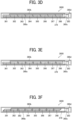
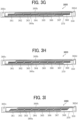
- the disposition of the resistance heating elements 361 to 368 is not limited to the state of FIG. 3A .
- gaps that lead in the lateral direction are present mutually between the resistance heating elements 361 to 368.
- end portions of resistance heating elements 361 to 368 overlap each other in the longitudinal direction.
- an L-shaped cut-away step is formed at each of the end portions of the resistance heating elements 361 to 368, so that the step overlaps the step of the end portion of the adjacent resistance heating element.
- an oblique cut-away inclination is formed at each of the end portions of the resistance heating elements 361 to 368, so that the inclination overlaps the inclination of the end portion of the adjacent resistance heating element.
- the electrodes 360c and 360d can be disposed on one side of the resistance heating elements 361 to 368 as in FIGS. 3D to 3F or FIGS. 3J to 3L . Disposing the electrodes 360c and 360d on the one side in this manner, can achieve space conservation in the longitudinal direction.
- FIG. 2A when a sheet P passes to the fixing nip SN in the arrow direction, the sheet P is heated between the fixing belt 310 and the pressing roller 320, so that the toner image is fixed to the sheet P.
- the fixing belt 310 is heated by heat from the heating member 360 while sliding on the insulating layer 370 of the heating member 360.
- the resistance heating element 364 does not rise in temperature.
- unnecessary power supply continues to the other normal resistance heating elements 361 to 363 and 365 to 368, so that unusual high temperature occurs.
- the occurrence of the unusual high temperature causes the power cutoff device CO to operate as in FIG. 5B , so that the power supply to the resistance heating elements 361 to 368 is interrupted.
- the second temperature sensor TH2 is disposed in the heating region of the resistance heating element 368 at the end portion, in the present embodiment.
- the second temperature sensor TH2 detects the temperature T 8 of the resistance heating element 368.
- the controller 400 controls the triac 420 so as to interrupt the supply current to the electrodes 360c and 360d. Therefore, even when the power cutoff device CO is not in operation as in FIG. 5A , the power supply to the resistance heating elements 361 to 368 is reliably interrupted, so that the occurrence of the unusual high temperature can be prevented.
- connection state assuming that, for example, the resistance heating element 368 of the plurality of resistance heating elements 361 to 368 is in disconnection state.
- the resistance heating element 368 is in disconnection state when a part of the pattern is broken.
- the resistance heating elements 361 to 368 are arranged in a rectangular pattern as illustrated in as illustrated in FIGS. 3A and 3B , the resistance heating element 368 is in disconnection state when the rectangular pattern is disconnected.
- the disconnection state means a state in which a path of a current flow is lost and no current flows.
- the "predetermined temperature information” includes not only that the temperature T 8 of the resistance heating element 368 satisfies T 8 ⁇ T N . That is the "predetermined temperature information” includes: (i) the temperature of the resistance heating element 368 is less than the predetermined temperature (Ts ⁇ T N ); (ii) the time until the temperature of the resistance heating element 368 reaches the predetermined temperature, is a predetermined time or more; and (iii) a variation in the temperature gradient is a predetermined value or less.
- the "predetermined time or more" in (ii) indicates, for example, that the time until the temperature reaches 100°C after the heater is switched on, is three seconds or more.
- the second temperature sensor TH2 may be allowed to detect that the resistance heating element 368 has an unusual high temperature that is the predetermined temperature or more (e.g., 250°C or more). This arrangement enables the power cutoff device CO to interrupt the power supply to the resistance heating elements 361 to 368 safely before operation at an unusual high temperature of 260°C or more, for example.
- the fixing device 300 is not limited to the first fixing device of FIG. 2A .
- the second to fourth fixing devices will be described below with reference to FIGS. 2B to 2D .
- the second fixing device including a pressure roller 390 on the opposite side of a pressing roller 320, heats a fixing belt 310 nipped between the pressure roller 390 and a heating device 3000.
- the heating device 3000 described above is arranged inside the fixing belt 310.
- a stay 330 has an auxiliary stay 331 attached on one side and a nip formation pad 332 attached on the opposite side.
- the auxiliary stay 331 holds the heating device 3000.
- the nip formation pad 332 abuts on the pressing roller 320 through the fixing belt 310, forming a fixing nip SN.
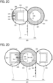
- the third fixing device includes a heating device 3000 arranged inside a fixing belt 310.
- the heating device 3000 has the cross sections of a base 350 and an insulating layer 370 formed in an arc shape meeting the curvature of the fixing belt 310, in order to lengthen a circumferentially contact length to the fixing belt 310.
- a heating member 360 is disposed at the center of the arc-shaped base 350.
- the third fixing device is identical to the second fixing device of FIG. 2B in terms of the others.
- the fourth fixing device includes a heating nip HN and a fixing nip SN separately. That is a nip formation pad 332 and a stay 333 including a metallic channel member are disposed on one side of a pressing roller 320 opposite to a fixing belt 310, and a pressing belt 334 is arranged circumferentially rotatably, enveloping the nip formation pad 332 and the stay 333. A sheet P passing through the fixing nip SN between the pressing belt 334 and the pressing roller 320, is subjected to heating and fixing.
- the fourth fixing device is identical to the first fixing device of FIG. 2A in terms of the others.
- the second temperature sensor TH2 for safety protection may be disposed crimped by a biasing means, on the inner circumferential face of the fixing belt 310 (inner circumferential face on the downstream side of the resistance heating element 368) to be heated by the resistance heating element 368 different from the resistance heating element 364 to be detected by the first temperature sensor TH1 for temperature control.
- a biasing means on the inner circumferential face of the fixing belt 310 (inner circumferential face on the downstream side of the resistance heating element 368) to be heated by the resistance heating element 368 different from the resistance heating element 364 to be detected by the first temperature sensor TH1 for temperature control.
- the second temperature sensor TH2 for safety protection may be disposed in each of the heating regions of the other resistance heating elements 361 to 363 and 365 to 367, including the inner circumferential face of the fixing belt 310.
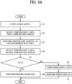
- FIG. 6A is a first flowchart of a control operation of the heating device 3000 to be performed by the controller 400 described above.
- the controller 400 starts power supply from the alternating-current power source 410 to the resistance heating elements 361 to 368 in the heating member 360.
- the first temperature sensor TH1 detects the temperature T 4 of the resistance heating element 364 located in the central region of the heating member 360.
- the controller 400 starts temperature control of the heating member 360.
- the second temperature sensor TH2 detects the temperature T 8 of the resistance heating element 368.
- the controller 400 determines whether the temperature T 8 satisfies T 8 ⁇ T N (T N : predetermined temperature).
- T 8 ⁇ T N the controller 400 determines as occurrence of unusual low temperature (disconnection), interrupts (cuts OFF) the power supply to the heating member 360, and at S7 displays an error display on an operation panel of the color laser printer 100.
- T 8 ⁇ T N is satisfied, the controller 400 determines as no occurrence of unusual low temperature and starts printing operation at step S8.
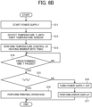
- FIG. 6B is a second flowchart of another control operation of the heating device 3000 to be performed by the controller 400 described above. Steps S11 to S13 and steps S16 to S18 in FIG. 6A are the same as steps S1 to S3 and steps S6 to S8 in FIG. 6A .
- the controller 400 determines whether the temperature T 4 of the first resistance heating element 364 detected by the first temperature sensor TH1 satisfies T 4 ⁇ T N (T N : predetermined temperature).
- the controller 400 determines as occurrence of unusual low temperature (disconnection), and at step S16 interrupts (cuts OFF) power supply to the heating member 360.
- the controller 400 displays an error display on the operation panel of the color laser printer 100.
- the controller 400 determines as no occurrence of unusual low temperature and starts printing operation at step S18.
- the controller 400 may determine whether the temperature T 8 of the second resistance heating element 368 detected by the second temperature sensor TH2 is T 8 ⁇ T N (TN: predetermined temperature).
- the power cutoff device CO is provided according to the embodiment described above, but the power cutoff device CO of FIG. 4 can be omitted according to a modification of the present embodiment. That is the triac 420 is directly connected to the electrode 360d without the power cutoff device CO. Meanwhile, the controller 400 interrupts the power supply to the plurality of resistance heating elements 361 to 368 when the second temperature sensor TH2 detects the predetermined temperature information regarding the resistance heating element 368, namely, the predetermined temperature or less (e.g., 100°C or less) or the predetermined temperature or more (e.g., 260°C or more).
- the predetermined temperature or less e.g., 100°C or less
- the predetermined temperature or more e.g., 260°C or more
- the second temperature sensor TH2 typically detects, for example, a temperature of 100°C or less when the resistance heating element 368 disconnects.
- the second temperature sensor TH2 may detect a temperature of 100°C or less due to failure of the alternating-current power source 410 or the triac 420.
- the second temperature sensor TH2 may detect the predetermined temperature information regarding at least one of the other resistance heating elements 361 to 367.
- a heating device 3000 can be used for a drying device other than a fixing device.
- a mode for the overlap between resistance heating elements recess-and-protrusion or comb-shaped interdigitation can be provided other than the modes in FIGS 3B and 3C , FIGS. 3E and 3F , FIGS. 3H and 3I , and FIGS. 3K and 3L .
- the number of resistance heating elements may be less than eight or not less than nine.
- resistance heating elements can be disposed in a plurality of lines in the lateral direction of a base 350.
Landscapes
- Physics & Mathematics (AREA)
- General Physics & Mathematics (AREA)
- Fixing For Electrophotography (AREA)
- Control Or Security For Electrophotography (AREA)
- Control Of Resistance Heating (AREA)
Applications Claiming Priority (3)
| Application Number | Priority Date | Filing Date | Title |
|---|---|---|---|
| JP2017249230 | 2017-12-26 | ||
| JP2018237465A JP7302167B2 (ja) | 2017-12-26 | 2018-12-19 | 加熱装置、定着装置及び画像形成装置 |
| EP18215082.1A EP3570114A1 (de) | 2017-12-26 | 2018-12-21 | Heizvorrichtung, fixiervorrichtung und bilderzeugungsvorrichtung |
Related Parent Applications (1)
| Application Number | Title | Priority Date | Filing Date |
|---|---|---|---|
| EP18215082.1A Division EP3570114A1 (de) | 2017-12-26 | 2018-12-21 | Heizvorrichtung, fixiervorrichtung und bilderzeugungsvorrichtung |
Publications (2)
| Publication Number | Publication Date |
|---|---|
| EP4339709A2 true EP4339709A2 (de) | 2024-03-20 |
| EP4339709A3 EP4339709A3 (de) | 2024-05-29 |
Family
ID=67304513
Family Applications (2)
| Application Number | Title | Priority Date | Filing Date |
|---|---|---|---|
| EP23218622.1A Pending EP4339709A3 (de) | 2017-12-26 | 2018-12-21 | Heizvorrichtung, fixiervorrichtung und bilderzeugungsvorrichtung |
| EP18215082.1A Withdrawn EP3570114A1 (de) | 2017-12-26 | 2018-12-21 | Heizvorrichtung, fixiervorrichtung und bilderzeugungsvorrichtung |
Family Applications After (1)
| Application Number | Title | Priority Date | Filing Date |
|---|---|---|---|
| EP18215082.1A Withdrawn EP3570114A1 (de) | 2017-12-26 | 2018-12-21 | Heizvorrichtung, fixiervorrichtung und bilderzeugungsvorrichtung |
Country Status (2)
| Country | Link |
|---|---|
| EP (2) | EP4339709A3 (de) |
| JP (2) | JP7302167B2 (de) |
Families Citing this family (6)
| Publication number | Priority date | Publication date | Assignee | Title |
|---|---|---|---|---|
| JP7302167B2 (ja) * | 2017-12-26 | 2023-07-04 | 株式会社リコー | 加熱装置、定着装置及び画像形成装置 |
| JP2021117298A (ja) * | 2020-01-23 | 2021-08-10 | 株式会社リコー | 加熱装置および画像形成装置 |
| JP7557711B2 (ja) * | 2020-12-01 | 2024-09-30 | 株式会社リコー | 定着装置及び画像形成装置 |
| CN116802567B (zh) * | 2021-01-28 | 2025-12-09 | 信越聚合物株式会社 | 定影垫 |
| JP7620877B2 (ja) | 2021-03-12 | 2025-01-24 | 株式会社リコー | 定着装置及び画像形成装置 |
| JP7630769B2 (ja) * | 2021-07-05 | 2025-02-18 | 株式会社リコー | 加熱装置、定着装置、画像形成装置 |
Citations (2)
| Publication number | Priority date | Publication date | Assignee | Title |
|---|---|---|---|---|
| JP2015194713A (ja) | 2014-03-19 | 2015-11-05 | キヤノン株式会社 | 像加熱装置及び像加熱装置に用いるヒータ |
| JP2016018127A (ja) | 2014-07-09 | 2016-02-01 | キヤノン株式会社 | 画像加熱装置 |
Family Cites Families (14)
| Publication number | Priority date | Publication date | Assignee | Title |
|---|---|---|---|---|
| JPH02309382A (ja) * | 1989-05-25 | 1990-12-25 | Ricoh Co Ltd | 加熱定着装置の制御装置 |
| JP2001242740A (ja) | 2000-02-28 | 2001-09-07 | Canon Inc | 定着装置及びこの定着装置を備える画像形成装置 |
| JP2006039143A (ja) * | 2004-07-26 | 2006-02-09 | Canon Inc | 画像形成装置およびその制御方法 |
| JP2009145386A (ja) * | 2007-12-11 | 2009-07-02 | Canon Inc | 画像形成装置 |
| JP4610629B2 (ja) * | 2008-03-31 | 2011-01-12 | シャープ株式会社 | 定着装置、及びこれを備えた画像形成装置 |
| JP4887398B2 (ja) * | 2009-05-26 | 2012-02-29 | シャープ株式会社 | 定着装置および該定着装置を備える画像形成装置 |
| JP5966378B2 (ja) * | 2012-01-23 | 2016-08-10 | 株式会社リコー | 定着装置及び画像形成装置 |
| JP2014016603A (ja) | 2012-06-11 | 2014-01-30 | Canon Inc | 画像加熱装置及びベルト交換方法 |
| JP6071366B2 (ja) | 2012-09-19 | 2017-02-01 | キヤノン株式会社 | ヒータ及びこのヒータを搭載する像加熱装置 |
| JP6198580B2 (ja) * | 2013-11-18 | 2017-09-20 | キヤノン株式会社 | 像加熱装置及びこの像加熱装置を搭載する画像形成装置 |
| JP2016139003A (ja) | 2015-01-27 | 2016-08-04 | キヤノン株式会社 | 像加熱装置 |
| JP6661311B2 (ja) * | 2015-09-11 | 2020-03-11 | キヤノン株式会社 | 像加熱装置及び像加熱装置に用いるヒータ |
| EP3495893A1 (de) * | 2017-12-08 | 2019-06-12 | Ricoh Company, Ltd. | Heizvorrichtung, fixiervorrichtung und bilderzeugungsvorrichtung |
| JP7302167B2 (ja) * | 2017-12-26 | 2023-07-04 | 株式会社リコー | 加熱装置、定着装置及び画像形成装置 |
-
2018
- 2018-12-19 JP JP2018237465A patent/JP7302167B2/ja active Active
- 2018-12-21 EP EP23218622.1A patent/EP4339709A3/de active Pending
- 2018-12-21 EP EP18215082.1A patent/EP3570114A1/de not_active Withdrawn
-
2023
- 2023-04-06 JP JP2023062304A patent/JP7569023B2/ja active Active
Patent Citations (2)
| Publication number | Priority date | Publication date | Assignee | Title |
|---|---|---|---|---|
| JP2015194713A (ja) | 2014-03-19 | 2015-11-05 | キヤノン株式会社 | 像加熱装置及び像加熱装置に用いるヒータ |
| JP2016018127A (ja) | 2014-07-09 | 2016-02-01 | キヤノン株式会社 | 画像加熱装置 |
Also Published As
| Publication number | Publication date |
|---|---|
| EP4339709A3 (de) | 2024-05-29 |
| EP3570114A1 (de) | 2019-11-20 |
| JP7302167B2 (ja) | 2023-07-04 |
| JP2019117377A (ja) | 2019-07-18 |
| JP2023085496A (ja) | 2023-06-20 |
| JP7569023B2 (ja) | 2024-10-17 |
Similar Documents
| Publication | Publication Date | Title |
|---|---|---|
| US10802427B2 (en) | Heating device for fixing device of image forming apparatus having plurality of resistance heating elements and power interrupter | |
| US11067924B2 (en) | Heating device, fixing device, and image forming apparatus | |
| EP3550373B1 (de) | Heizer, fixiervorrichtung und bilderzeugungsvorrichtung | |
| EP4339709A2 (de) | Heizvorrichtung, fixiervorrichtung und bilderzeugungsvorrichtung | |
| JP2023099624A (ja) | 画像形成装置 | |
| US10712695B2 (en) | Image forming apparatus configured to control a lighting duty of a heat generator | |
| JP7087501B2 (ja) | 加熱装置、定着装置及び画像形成装置 | |
| US10539912B1 (en) | Image forming apparatus | |
| JP7183518B2 (ja) | 画像形成装置 | |
| US10802431B2 (en) | Heating device, fixing device, and image forming apparatus | |
| US20200379384A1 (en) | Heating device, fixing device, and image forming apparatus | |
| KR20210028692A (ko) | 상 가열 장치 및 화상 형성 장치 | |
| JP7562238B2 (ja) | 加熱装置、定着装置及び画像形成装置 | |
| US11573513B2 (en) | Heating device, fixing device, and image forming apparatus | |
| JP7130189B2 (ja) | 画像形成装置 | |
| JP7157910B2 (ja) | 加熱装置、定着装置及び画像形成装置 | |
| JP2019184980A (ja) | 画像形成装置 | |
| JP2019164343A (ja) | 画像形成装置 | |
| JP2020016747A (ja) | 加熱装置、定着装置及び画像形成装置 | |
| JP7330442B2 (ja) | 画像形成装置 | |
| JP2020024349A (ja) | 加熱装置、定着装置及び画像形成装置 | |
| JP7276700B2 (ja) | 定着装置および画像形成装置 |
Legal Events
| Date | Code | Title | Description |
|---|---|---|---|
| PUAI | Public reference made under article 153(3) epc to a published international application that has entered the european phase |
Free format text: ORIGINAL CODE: 0009012 |
|
| STAA | Information on the status of an ep patent application or granted ep patent |
Free format text: STATUS: REQUEST FOR EXAMINATION WAS MADE |
|
| 17P | Request for examination filed |
Effective date: 20231220 |
|
| AC | Divisional application: reference to earlier application |
Ref document number: 3570114 Country of ref document: EP Kind code of ref document: P |
|
| AK | Designated contracting states |
Kind code of ref document: A2 Designated state(s): AL AT BE BG CH CY CZ DE DK EE ES FI FR GB GR HR HU IE IS IT LI LT LU LV MC MK MT NL NO PL PT RO RS SE SI SK SM TR |
|
| PUAL | Search report despatched |
Free format text: ORIGINAL CODE: 0009013 |
|
| AK | Designated contracting states |
Kind code of ref document: A3 Designated state(s): AL AT BE BG CH CY CZ DE DK EE ES FI FR GB GR HR HU IE IS IT LI LT LU LV MC MK MT NL NO PL PT RO RS SE SI SK SM TR |
|
| RIC1 | Information provided on ipc code assigned before grant |
Ipc: G03G 15/20 20060101AFI20240423BHEP |