EP4339477B1 - Einwegkupplung - Google Patents
Einwegkupplung Download PDFInfo
- Publication number
- EP4339477B1 EP4339477B1 EP23194054.5A EP23194054A EP4339477B1 EP 4339477 B1 EP4339477 B1 EP 4339477B1 EP 23194054 A EP23194054 A EP 23194054A EP 4339477 B1 EP4339477 B1 EP 4339477B1
- Authority
- EP
- European Patent Office
- Prior art keywords
- portions
- way clutch
- retainer
- race
- outer race
- Prior art date
- Legal status (The legal status is an assumption and is not a legal conclusion. Google has not performed a legal analysis and makes no representation as to the accuracy of the status listed.)
- Active
Links
Images


Classifications
-
- F—MECHANICAL ENGINEERING; LIGHTING; HEATING; WEAPONS; BLASTING
- F16—ENGINEERING ELEMENTS AND UNITS; GENERAL MEASURES FOR PRODUCING AND MAINTAINING EFFECTIVE FUNCTIONING OF MACHINES OR INSTALLATIONS; THERMAL INSULATION IN GENERAL
- F16D—COUPLINGS FOR TRANSMITTING ROTATION; CLUTCHES; BRAKES
- F16D41/00—Freewheels or freewheel clutches
- F16D41/06—Freewheels or freewheel clutches with intermediate wedging coupling members between an inner and an outer surface
- F16D41/069—Freewheels or freewheel clutches with intermediate wedging coupling members between an inner and an outer surface the intermediate members wedging by pivoting or rocking, e.g. sprags
- F16D41/07—Freewheels or freewheel clutches with intermediate wedging coupling members between an inner and an outer surface the intermediate members wedging by pivoting or rocking, e.g. sprags between two cylindrical surfaces
- F16D41/073—Freewheels or freewheel clutches with intermediate wedging coupling members between an inner and an outer surface the intermediate members wedging by pivoting or rocking, e.g. sprags between two cylindrical surfaces each member comprising at least two elements at different radii
Definitions
- the present invention relates to a one-way clutch used for transmitting a torque in vehicles or industrial machinery.
- the retainer ring of the one-way clutch of the Patent document 1 supports an outer race and an inner race coaxially.
- the retainer ring is formed with cut-away portions extended axially with predetermined circumferential intervals, taking assembling the outer race and the inner race into consideration.
- Patent Document 1 Japan Patent Application laid-open No.H7-208506
- US 5 894 915 A relates to a one way clutch which is incorporated between a driving shaft and a driven shaft and has a function of transferring only power in a one way rotation of te driving shaft to the driven shaft.
- a one-way clutch having an inner race, an outer race arranged on a center axis of said inner race coaxially therewith, a plurality of cam members interposed between said inner race and said outer race to serve torque transmission between said inner race and said outer race, a retainer member for holding the plurality of said cam members, and a spring member biassing the plurality of said cam members to no torque transmitting positions, being characterized in that:
- the present invention can provide a structure of a one-way clutch that can be assembled easily without damaging the retainer and reduced in weight.
- center axis C refers to the center axis of the one-way clutch, that is, the center axis of the outer race or the inner race
- axial direction refers to the axial direction, radial direction, and circumferential direction with respect to that center axis C.
- the term “one axial direction” refers to the axial direction approaching the viewer on the front side of the plane of the drawing sheet of each of Figs. 1 , 4A and 4B
- the term “the other axial direction” refers to the axial direction becoming distant away from the viewer on the back side of the plane of the drawing sheet of each of Figs. 1 , 4A and 4B
- the left side of the drawing sheet is the one axial side
- the right side of the drawing sheet is the other axial side.
- the term “one circumferential direction” refers to the clockwise rotating direction toward the drawing sheet
- the term “the other circumferential direction” refers to the counter clockwise rotating direction toward the drawing sheet.
- Fig. 1 is a front view of a one-way clutch 1 according to the embodiment showing a state seen from the one axial side.
- Fig. 2 is a side view of the one-way clutch 1 according to the embodiment showing a state seen from the radial direction.
- Fig. 3 is a perspective view showing an appearance of the one-way clutch 1 according to the embodiment.
- the inner race 3 and the outer race 5 are shown by imaginary lines in Fig. 2 , and are omitted in Fig. 1 and Fig.3 .
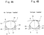
- Figs. 4A and 4B is enlarged cross sectional views of an essential portion, showing states of a cam member 7 of the one-way clutch 1 according to the embodiment, Fig. 4A showing no torque loaded state and Fig. 4B showing a torque loaded state.
- the one-way clutch 1 includes an inner race 3 and an outer race 5 arranged coaxially on the center axis C, a plurality of cam members 7 interposed between the inner race 3 and the outer race 5, a ring-shaped retainer 9 for holding the plurality of the cam members 7, and a spring member 15 biassing the plurality of the cam members 7 into a direction to be in contact with the inner circumferential surface 11 of the outer race and the outer circumferential surface 13 of the inner race (refer to Figs. 4A and 4B ) in no torque transmitting state.
- the spring member 15 is a garter spring.
- the plurality of cam members 7 are torque-transmitting members which are brought into engagement with the outer peripheral surface 11 of the inner race 3 and the inner peripheral surface 13 of the outer race 5 to transmit torque from the inner race 3 to the outer race 5.
- the cam members 7 each is column-shaped whose peripheral surface is curved.
- a cross-section of the cam member 7 has a shape which is a combination of a semicircular portion 17 and an inflated or bulged portion 19 that inflates or bulges outwardly from a line connecting both ends of a circle arc of the semicircular portion 17, as shown in Figs. 4A and 4B .
- the inflated or bulged portion 19 has a top portion that is round and gently mountainous.
- an end of the contour of the inflated or bulged portion 19 and the other end of the contour of the inflated or bulged portion 19 are smoothly continuous to, respectively, an end of the arc of the semicircular portion 17 and the other end of the arc of the semicircular portion 17.
- the cam member 7 is so formed that the length of the straight line connecting the top portion of the inflated or bulged portion 19 and the bottom of the arc of the semicircular portion 17 is shorter than the length connecting the vicinities of both ends of the arc of the semicircular portion 17.
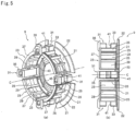
- Fig. 5A is a perspective view showing an appearance of the retainer 9
- Fig. 5B is a side view of the retainer 9.
- the retainer 9 as a whole is formed integrally of a resin.
- the retainer 9 is integrally provided with an annular plate 21 arranged at the other axial side of the inner race 3 and the other axial side of the outer race 5 on the center axis C and the plurality of the cam member holding portions 23 projected from the one axial side surface of the annular plate 21 in the one axial direction thereof.
- cam member holding portions 23 Next, a structure of one of the cam member holding portions 23 will be explained.
- the remaining cam member holding portions 23 have the same structure.
- the cam member holding portion 23 is integrally composed of a plurality of column portions 25 arranged equidistantly in the circumferential direction and projected from the one axial side surface of the annular plate 21 to the one axial direction and an arcuate flange 27 integrally connecting the one axial side ends of the plurality of the column portions 25. Accordingly, the cam member holding portion 23 is partial-cylindrical. In the present embodiment, there are four column portions 25.
- the cross section of the column portion 25 is rectangular and shaped to be formed by radially extended sides and circumferentially extended sides, as shown in each of Figs. 4A and 4B .
- the cross section of the column portion 25 has an oblong shape whose radially extended sides are longer than circumferentially extended sides.
- the inner circumferential surfaces of the respective column portions 25 and the inner circumferential surface of the flange portion 27 are smoothly continuous and arranged on the surface of an imaginary cylinder centered on the center axis C.
- the cam member holding portion 23 has three window portions 29 radially formed therethrough arranged equidistantly in the circumferential direction, defined by four column portions 25, the flange portion 27 and a portion of the annular plate 21.
- each window portion 29 is defined by a pair of column portions 25 neighboring each other in the circumferential direction, a portion of the flange 27 and a portion of the annular plate 21 axially opposed to each other between the pair of the column portions 25 neighboring each other.
- one cam member 7 is swingably held, as described later.
- cam member holding portions 23 having respectively such configurations as above described are arranged circumferentially equally spaced on the circumference of an imaginal circle centered on the center axis C, seen from the axial direction. Accordingly, the inner circumferential surface of each column member 25 and the inner circumferential surface of each flange portion 27 of the four holding portions 23 are arranged on one imaginary cylindrical surface centered on the center axis C.
- the retainer 9 is further formed with a plurality of bearing portions 31 each being rectangular-column shaped and projected from the one axial side surface of the annular plate 21 in the one axial direction.
- the number of the bearing portions 31 is the same as the number of the cam member holding portions 23. Accordingly, in the present embodiment, there are four bearing portions 31.
- the bearing portions 31 and the cam member holding portions 23 are arranged alternately in the circumferential direction. Concretely, one bearing portion 31 is arranged between the circumferentially neighboring cam member holding portions 23. Accordingly, the plurality of the cam member holding portions 23 and the plurality of the bearing portions 31 are arranged alternately on the circumference of one imaginary circle centered on the center axis C, viewed from the axial direction.
- the four bearing portions 31 are arranged on the diagonal positions of equal angles over the circumferential direction, in other words, 90 °distant angular positions over the circumferential direction with respect to the center axis C, seen from the axial direction.
- the inner circumferential surface of the bearing portion 31 is arranged on an imaginary cylindrical surface that differs from the inner circumferential surface of the cam member holding portions 23, that is, the inner circumferential surfaces of the column portions 25 and the inner circumferential surface of the inner cylindrical surface of the flange portion 27.
- the plurality of the cam member holding portions 23 and the plurality of the bearing portions 31 are arranged between the outer peripheral surface 11 of the inner race 3 and the inner13 peripheral surface 11 of the outer race 5.
- the inner race 3 is arranged at the radially inner side of the bearing portions 31 and the cam member holding portions 23, as shown in Fig. 2 .
- the bearing portions 31 support, on the outer circumferential surfaces thereof, the outer race 5.
- the outer circumferential surface 33 of the bearing portion 31 may be a curved surface having a curvature radius differing from that of the inner peripheral surface 13 of the outer race 5.
- the one axial side end of the bearing portion 31 is formed with a flange portion 35 projected radially outwardly.
- the annular plate 21 is formed with a flange portion 22 which is more radially outwardly extended than a portion of the annular plate 21 formed with the plurality of the cam member holding portions 23 and the plurality of the bearing portions 31.
- the retainer 9 is arranged such that the flange portion 22 of the annular plate 21 is fitted in a circumferentially extended groove 37 formed on the inner peripheral surface 13 of the outer race 5, and the flange portion 35 of the bearing portion 31 is opposed in the axial direction to the one axial side end of the outer race 5.
- the retainer 9 is fixed to the outer race 5 to be impossible to move in the axial direction and impossible to rotate relatively in the circumferential direction.
- the plurality of the cam members 7 are fitted in the window portions 29 of the retainer 9 respectively with one to one relationship from the radially outer side, with the axial direction of each cam member 7 being the same as the axial direction of the one-way clutch 1.
- the plurality of the cam members 7 are held circumferentially by the retainer 9.
- One cam member holding member 23 holds a plurality of the cam members 7 equiangularly in the circumferential direction.
- three cam members 7 are held in the one cam member holding portion 23. Surfaces of the opposite ends of each cam member 7 are located inside of a portion of the flange 27 and a portion of the annular plate 21 axially opposed to each other in the window portion 29 of the retainer 9.
- the axial size of the cam member 7 is smaller than the axial size of the window portion 9.
- the semicircular portion 17 of the cam member 7 faces the inner race 3 and the bottom of the semicircular portion 17 is in contact with the outer peripheral surface 11 of the inner race 3, while the bulged portion 19 faces the outer race 5 and the top of the bulged portion 19 is in contact with the inner peripheral surface 13 of the outer race 5.
- a circumference of the semicircular portion 17 of the cam member 7 is in contact with the pair of column portions 25 defining the window portion 29 of the retainer 9, and a part of the semicircular portion 17 passes through the window portion 29 of the retainer 9 and projects radially more inwardly than the pair of column portions 25.
- the cam member 7 is held in the window portion 29 of the retainer 9 and in contact with the outer circumferential surface 11 of inner race 3 stably.
- the cam member 7 may swing with in slide-contact with the pair of column portions 25 and the movement of the cam member 7 in the axial direction is restricted by the flange 27 and the annular plate 21.
- each cam member 7, at the radially outer portion thereof in the assembled state is formed with a groove 39 extended in the circumferential direction of the inner race 3 or the outer race 5.
- the groove 39 is formed in the axially central portion of the radially outer peripheral portion of the cam member 7, and is formed circumferentially through the radially outer peripheral portion of the cam member 7.
- the groove 39 has a depth reaching the vicinity of the central portion of the cam member 7.
- each bearing portion 31, at the radially outer portion thereof is formed with a groove 41 extended in the circumferential direction.
- the bearing portion 31 is formed, at the axially central portion of the radially outer circumferential portion thereof, with the groove 41.
- the groove 41 is formed circumferentially through the radially outer circumferential portion of the bearing portion 31 and has a depth reaching the vicinity of the central portion of the bearing portion 31.
- One annular spring member 15 is provided through the grooves 39 of the respective cam members 7 and the grooves 41 of the respective bearing portions 31.
- the spring member 15 biases the respective cam members 7 radially inwardly.
- the bottom surface of the groove 39 of each cam member 7 is formed in a mountain shape having an angle such that the cam members 7, with biased radially inwardly by the spring member 15, swing in the direction in which the cam members 7 are in contact with the outer peripheral surface 11 of the inner race 3 and the inner circumferential surface 13 of the outer race 5. Accordingly, the respective cam members 7 are biased radially inwardly by the elastic force of the spring member 15 to be always in contact with the outer circumferential surface 11 of the inner race 3 and the inner peripheral surface 13 of the outer race 5.
- each cam member 7 In this state of contact of each cam member 7 with the outer peripheral surface 11 of the inner race 3 and the inner peripheral surface 13 of the outer race 5, as shown in Fig. 4A , no torque is transmitted. As described, the spring member 15 biases the respective cam members 7 into no torque transmitting positions.
- the retainer 9 is provided with a pair of radially extending cut-away portions 43 on the circumferential one side and circumferential other side of each bearing portion 31.
- Each of cut-away portions 43 is formed axially through the annular plate 21 and the flange portion 22 of the retainer 9 and forms a space having a predetermined width and extending radially.
- Each cut-away portions 43 open on the outer diameter side of the flange 22 of the annular plate 21 and extend to a radial position on the more inner diameter side than the cam member holding portion 23.
- the retainer 9 has four pairs of the cut-away portions 43, in other words, is formed with eight cut-away portions 43.
- the paired cut-away portions 43 are parallel to each other.
- the annular plate 21 is formed with cut-away portions 45 each forming a space that opens on the radially inner side and extending substantially radially, with a predetermined width, to a position in the vicinity of the cam member holding portion 23.
- cut-away portions 45 There are four such cut-away portions 45 with equal intervals in the circumferential direction.
- the number of the cut-away portions 45 is the same as the number of the bearing portions 31.
- the cut-away portions 45 and the bearing portions 31 are alternately arranged in the circumferential direction.
- cut-away portion 45 is located in the middle between the neighboring bearing portions 31, seen from the axial direction.
- the retainer 9 Since the retainer 9 has a structure made of a resin and is formed with the cut-away portions 43 and 45, the retainer 9 can deform elastically in the radial direction. Concretely, upon an external force being applied radially, the widths of the cut-away portions 43 and 45 change and elastic deformation of the retainer occurs. By such structure, improved assembling of the inner race 3 and the outer race 5 to the retainer 9 can be made without damaging the retainer 9.
- the one-way clutch 1 since the retainer 9 is able to deform elastically in the radial direction, the one-way clutch 1 according to the present embodiment may be assembled easily in automatic transmission or industrial machinery with no damage to the retainer 9.
- the respective cam members 7 swing to be brought into engagement with the inner race 3 and the outer race 5 so as to transmit torque.
- the cam members 7 rotate or swing counterclockwise by friction, and are brought into engagement with the outer circumferential surface 11 of the inner race 3 and the inner circumferential surface 13 of the outer race 5, by such engagement torque being transmitted from the inner race 3 to the outer race 5.
- the inner peripheral surface 13 of the outer race 5 is supported by the four bearing portions 31 formed integrally with the retainer 9 and arranged at 90°angular positions along the circumferential direction with respect to the center axis C, so the retainer 9 and the outer race 5 rotate stably together with the inner race 3 in a body.
- the plurality of the cam members 7 are held by four cam holding members 23 which are arranged at 90°angular positions along the circumferential direction with respect to the center axis C, and which respectively hold three cam members, thereby stable engagement between the inner race 3 and the outer race 5 is attained over the circumferential direction. As a result, the inner race 3 and the outer race 5 rotate stably.
- the retainer 9 is composed of a resin, one-way clutch 1 and automatic transmission in which the one-way clutches are assembled can be reduced in weight. Further, the retainer 9 is integrally formed with the bearing portions 31 for supporting the inner peripheral surface 13 of the outer race 5, so no separate bearing is required to support the outer race 5. For this reason, increase in axial dimension of the one-way clutch 1 is prevented, and space for mounting the one-way clutch can be made small and the number of parts can be reduced. Thus, weight reduction of the one-way clutch can be realized.
- the one-way clutch 1 according to the present invention is not limited to the above embodiment but may be modified properly.
- an example of the one-way clutch that transmits torque from the inner race 3 to the outer race 5 has been illustrated, but the present invention may be applied to a one-way clutch which transmits torque from the outer race 5 to the inner race 3.
- the number of the bearing portions 31 and the number of the cam member holding portions 23 also can be changed properly, depending on the size of the one-way clutch, torque capacity or the like.
- the number of the cam members 7 held by one cam member holding portion 23 may be changed properly also.
- the number of the cut-away portions 43 and 45 may be changed properly.
Landscapes
- Engineering & Computer Science (AREA)
- General Engineering & Computer Science (AREA)
- Mechanical Engineering (AREA)
- Rolling Contact Bearings (AREA)
- Mechanical Operated Clutches (AREA)
Claims (5)
- Einwegkupplung, die Folgendes aufweist:einen inneren Laufring (3);einen äußeren Laufring (5), der auf einer Mittelachse des inneren Laufrings koaxial damit angeordnet ist,eine Vielzahl von Nockenelementen (7), die zwischen dem inneren Laufring und dem äußeren Laufring angeordnet sind, um der Drehmomentübertragung zwischen dem inneren Laufring und dem äußeren Laufring zu dienen;ein Halteelement (9) zum Halten der Vielzahl von Nockenelementen; undein Federelement (15), das die Vielzahl von Nockenelementen in nicht drehmomentübertragende Stellungen spannt, dadurch gekennzeichnet, dass:das Halteelement (9) mit einer auf der Mittelachse angeordneten ringförmigen Platte (21) versehen ist, wobei das Plattenelement (21) auf einer axialen Seitenoberfläche davon mit einer Vielzahl von Lagerabschnitten (31), die die Innenumfangsoberfläche des äußeren Laufrings (5) stützen, und der gleichen Anzahl von Halteabschnitten (23) wie die Anzahl der Lagerabschnitte versehen ist, wobei die Halteabschnitte jeweils eine vorgegebene Anzahl von zweien oder mehr der Nockenelemente mit vorgegebenen Abständen entlang der Umfangsrichtung halten,die Vielzahl der Lagerabschnitte (31) jeweils in Bezug auf die Mittelachse an diagonalen Positionen entlang der Umfangsrichtung gleichwinklig angeordnet sind, wobei die Vielzahl von Halteabschnitten (23) jeweils in Bezug auf die Mittelachse an diagonalen Positionen entlang der Umfangsrichtung gleichwinklig angeordnet sind;die Vielzahl der Lagerabschnitte (31) und die Vielzahl der Halteabschnitte (23) abwechselnd entlang der Umfangsrichtung angeordnet sind; unddie ringförmige Platte (21) mit einer Vielzahl von sich radial erstreckenden ausgeschnittenen Abschnitten (43, 45) gebildet ist.
- Einwegkupplung nach Anspruch 1, wobei der Halter aus einem Harz gebildet ist.
- Einwegkupplung nach Anspruch 1 oder Anspruch 2,
wobei die Vielzahl der ausgeschnittenen Abschnitte (43, 45) eine Vielzahl von ersten ausgeschnittenen Abschnitten (43), die radial in Richtung auf außerhalb der ringförmigen Platte offen sind, und eine Vielzahl von zweiten ausgeschnittenen Abschnitten (45), die radial in Richtung auf innerhalb der ringförmigen Platte offen sind, umfasst. - Einwegkupplung nach Anspruch 3, wobei die ersten ausgeschnittenen Abschnitte (43) den Lagerelementen (31) benachbart gebildet sind.
- Einwegkupplung nach Anspruch 3, wobei die zweiten ausgeschnittenen Abschnitte (45) und die Vielzahl der Lagerabschnitte (31) in der Umfangsrichtung abwechselnd angeordnet sind.
Applications Claiming Priority (2)
| Application Number | Priority Date | Filing Date | Title |
|---|---|---|---|
| JP2022146292A JP7814085B2 (ja) | 2022-09-14 | 2022-09-14 | ワンウェイクラッチ |
| JP2022147174A JP7814086B2 (ja) | 2022-09-15 | 2022-09-15 | ワンウェイクラッチ |
Publications (2)
| Publication Number | Publication Date |
|---|---|
| EP4339477A1 EP4339477A1 (de) | 2024-03-20 |
| EP4339477B1 true EP4339477B1 (de) | 2025-03-26 |
Family
ID=87863391
Family Applications (2)
| Application Number | Title | Priority Date | Filing Date |
|---|---|---|---|
| EP23194054.5A Active EP4339477B1 (de) | 2022-09-14 | 2023-08-29 | Einwegkupplung |
| EP23194051.1A Active EP4339476B1 (de) | 2022-09-14 | 2023-08-29 | Einwegkupplung |
Family Applications After (1)
| Application Number | Title | Priority Date | Filing Date |
|---|---|---|---|
| EP23194051.1A Active EP4339476B1 (de) | 2022-09-14 | 2023-08-29 | Einwegkupplung |
Country Status (1)
| Country | Link |
|---|---|
| EP (2) | EP4339477B1 (de) |
Family Cites Families (3)
| Publication number | Priority date | Publication date | Assignee | Title |
|---|---|---|---|---|
| JPH0610230Y2 (ja) * | 1988-11-17 | 1994-03-16 | エヌティエヌ株式会社 | 一方向クラッチ付き回転体 |
| JPH07208506A (ja) | 1994-01-26 | 1995-08-11 | Nsk Warner Kk | 一方向クラッチ |
| JP3703564B2 (ja) * | 1996-04-30 | 2005-10-05 | Nskワーナー株式会社 | 一方向クラッチ |
-
2023
- 2023-08-29 EP EP23194054.5A patent/EP4339477B1/de active Active
- 2023-08-29 EP EP23194051.1A patent/EP4339476B1/de active Active
Also Published As
| Publication number | Publication date |
|---|---|
| EP4339476A1 (de) | 2024-03-20 |
| EP4339477A1 (de) | 2024-03-20 |
| EP4339476B1 (de) | 2025-04-02 |
Similar Documents
| Publication | Publication Date | Title |
|---|---|---|
| US20140011629A1 (en) | Continuously variable transmission | |
| US5024308A (en) | One-way clutch and holder for torque transmitting members thereof | |
| US10655691B2 (en) | One-way clutch apparatus | |
| KR101920577B1 (ko) | 트러스트 베어링 및 그 제조 방법 | |
| JP2008267563A (ja) | スプリングクラッチ | |
| EP4339477B1 (de) | Einwegkupplung | |
| JPH02286920A (ja) | トリポット型等速ジョイント | |
| US4579465A (en) | Self-centering bearing | |
| JP2020133686A (ja) | ワンウェイクラッチ | |
| JP5169794B2 (ja) | クラッチ機構付増速装置 | |
| JP7814086B2 (ja) | ワンウェイクラッチ | |
| JP7141239B2 (ja) | ワンウェイクラッチ | |
| JP7814085B2 (ja) | ワンウェイクラッチ | |
| US11512744B2 (en) | Clutch apparatus | |
| US7766141B2 (en) | Outer retainer for one-way clutch | |
| CN111801508B (zh) | 单向离合器 | |
| EP4375529B1 (de) | Kupplungsvorrichtung | |
| JP2019065943A (ja) | 小型構造の逆入力遮断クラッチ | |
| JP7192466B2 (ja) | 動力伝達装置 | |
| JP2017214943A (ja) | 逆入力防止クラッチ | |
| JP2005248998A (ja) | 等速ジョイント | |
| JP2012013207A (ja) | トリポード型等速ジョイント | |
| JP2025042324A (ja) | 回転伝達装置 | |
| JP7606099B2 (ja) | カム及び一方向カムクラッチ | |
| JP7735032B2 (ja) | ラチェット型ワンウェイクラッチ |
Legal Events
| Date | Code | Title | Description |
|---|---|---|---|
| PUAI | Public reference made under article 153(3) epc to a published international application that has entered the european phase |
Free format text: ORIGINAL CODE: 0009012 |
|
| STAA | Information on the status of an ep patent application or granted ep patent |
Free format text: STATUS: THE APPLICATION HAS BEEN PUBLISHED |
|
| AK | Designated contracting states |
Kind code of ref document: A1 Designated state(s): AL AT BE BG CH CY CZ DE DK EE ES FI FR GB GR HR HU IE IS IT LI LT LU LV MC ME MK MT NL NO PL PT RO RS SE SI SK SM TR |
|
| STAA | Information on the status of an ep patent application or granted ep patent |
Free format text: STATUS: REQUEST FOR EXAMINATION WAS MADE |
|
| 17P | Request for examination filed |
Effective date: 20240906 |
|
| RBV | Designated contracting states (corrected) |
Designated state(s): AL AT BE BG CH CY CZ DE DK EE ES FI FR GB GR HR HU IE IS IT LI LT LU LV MC ME MK MT NL NO PL PT RO RS SE SI SK SM TR |
|
| GRAP | Despatch of communication of intention to grant a patent |
Free format text: ORIGINAL CODE: EPIDOSNIGR1 |
|
| STAA | Information on the status of an ep patent application or granted ep patent |
Free format text: STATUS: GRANT OF PATENT IS INTENDED |
|
| RIC1 | Information provided on ipc code assigned before grant |
Ipc: F16D 41/07 20060101AFI20241111BHEP |
|
| INTG | Intention to grant announced |
Effective date: 20241122 |
|
| GRAS | Grant fee paid |
Free format text: ORIGINAL CODE: EPIDOSNIGR3 |
|
| GRAA | (expected) grant |
Free format text: ORIGINAL CODE: 0009210 |
|
| STAA | Information on the status of an ep patent application or granted ep patent |
Free format text: STATUS: THE PATENT HAS BEEN GRANTED |
|
| AK | Designated contracting states |
Kind code of ref document: B1 Designated state(s): AL AT BE BG CH CY CZ DE DK EE ES FI FR GB GR HR HU IE IS IT LI LT LU LV MC ME MK MT NL NO PL PT RO RS SE SI SK SM TR |
|
| REG | Reference to a national code |
Ref country code: GB Ref legal event code: FG4D |
|
| REG | Reference to a national code |
Ref country code: CH Ref legal event code: EP |
|
| REG | Reference to a national code |
Ref country code: DE Ref legal event code: R096 Ref document number: 602023002584 Country of ref document: DE |
|
| REG | Reference to a national code |
Ref country code: IE Ref legal event code: FG4D |
|
| PG25 | Lapsed in a contracting state [announced via postgrant information from national office to epo] |
Ref country code: RS Free format text: LAPSE BECAUSE OF FAILURE TO SUBMIT A TRANSLATION OF THE DESCRIPTION OR TO PAY THE FEE WITHIN THE PRESCRIBED TIME-LIMIT Effective date: 20250626 |
|
| PG25 | Lapsed in a contracting state [announced via postgrant information from national office to epo] |
Ref country code: FI Free format text: LAPSE BECAUSE OF FAILURE TO SUBMIT A TRANSLATION OF THE DESCRIPTION OR TO PAY THE FEE WITHIN THE PRESCRIBED TIME-LIMIT Effective date: 20250326 |
|
| REG | Reference to a national code |
Ref country code: LT Ref legal event code: MG9D |
|
| PG25 | Lapsed in a contracting state [announced via postgrant information from national office to epo] |
Ref country code: NO Free format text: LAPSE BECAUSE OF FAILURE TO SUBMIT A TRANSLATION OF THE DESCRIPTION OR TO PAY THE FEE WITHIN THE PRESCRIBED TIME-LIMIT Effective date: 20250626 |
|
| PG25 | Lapsed in a contracting state [announced via postgrant information from national office to epo] |
Ref country code: HR Free format text: LAPSE BECAUSE OF FAILURE TO SUBMIT A TRANSLATION OF THE DESCRIPTION OR TO PAY THE FEE WITHIN THE PRESCRIBED TIME-LIMIT Effective date: 20250326 |
|
| PG25 | Lapsed in a contracting state [announced via postgrant information from national office to epo] |
Ref country code: LV Free format text: LAPSE BECAUSE OF FAILURE TO SUBMIT A TRANSLATION OF THE DESCRIPTION OR TO PAY THE FEE WITHIN THE PRESCRIBED TIME-LIMIT Effective date: 20250326 |
|
| PG25 | Lapsed in a contracting state [announced via postgrant information from national office to epo] |
Ref country code: GR Free format text: LAPSE BECAUSE OF FAILURE TO SUBMIT A TRANSLATION OF THE DESCRIPTION OR TO PAY THE FEE WITHIN THE PRESCRIBED TIME-LIMIT Effective date: 20250627 Ref country code: BG Free format text: LAPSE BECAUSE OF FAILURE TO SUBMIT A TRANSLATION OF THE DESCRIPTION OR TO PAY THE FEE WITHIN THE PRESCRIBED TIME-LIMIT Effective date: 20250326 |
|
| REG | Reference to a national code |
Ref country code: NL Ref legal event code: MP Effective date: 20250326 |
|
| PG25 | Lapsed in a contracting state [announced via postgrant information from national office to epo] |
Ref country code: NL Free format text: LAPSE BECAUSE OF FAILURE TO SUBMIT A TRANSLATION OF THE DESCRIPTION OR TO PAY THE FEE WITHIN THE PRESCRIBED TIME-LIMIT Effective date: 20250326 |
|
| PG25 | Lapsed in a contracting state [announced via postgrant information from national office to epo] |
Ref country code: SE Free format text: LAPSE BECAUSE OF FAILURE TO SUBMIT A TRANSLATION OF THE DESCRIPTION OR TO PAY THE FEE WITHIN THE PRESCRIBED TIME-LIMIT Effective date: 20250326 |
|
| REG | Reference to a national code |
Ref country code: AT Ref legal event code: MK05 Ref document number: 1779251 Country of ref document: AT Kind code of ref document: T Effective date: 20250326 |
|
| PG25 | Lapsed in a contracting state [announced via postgrant information from national office to epo] |
Ref country code: SM Free format text: LAPSE BECAUSE OF FAILURE TO SUBMIT A TRANSLATION OF THE DESCRIPTION OR TO PAY THE FEE WITHIN THE PRESCRIBED TIME-LIMIT Effective date: 20250326 |
|
| PG25 | Lapsed in a contracting state [announced via postgrant information from national office to epo] |
Ref country code: ES Free format text: LAPSE BECAUSE OF FAILURE TO SUBMIT A TRANSLATION OF THE DESCRIPTION OR TO PAY THE FEE WITHIN THE PRESCRIBED TIME-LIMIT Effective date: 20250326 Ref country code: PT Free format text: LAPSE BECAUSE OF FAILURE TO SUBMIT A TRANSLATION OF THE DESCRIPTION OR TO PAY THE FEE WITHIN THE PRESCRIBED TIME-LIMIT Effective date: 20250728 |
|
| PGFP | Annual fee paid to national office [announced via postgrant information from national office to epo] |
Ref country code: DE Payment date: 20250702 Year of fee payment: 3 |
|
| PG25 | Lapsed in a contracting state [announced via postgrant information from national office to epo] |
Ref country code: PL Free format text: LAPSE BECAUSE OF FAILURE TO SUBMIT A TRANSLATION OF THE DESCRIPTION OR TO PAY THE FEE WITHIN THE PRESCRIBED TIME-LIMIT Effective date: 20250326 |
|
| PGFP | Annual fee paid to national office [announced via postgrant information from national office to epo] |
Ref country code: IT Payment date: 20250901 Year of fee payment: 3 |
|
| PG25 | Lapsed in a contracting state [announced via postgrant information from national office to epo] |
Ref country code: AT Free format text: LAPSE BECAUSE OF FAILURE TO SUBMIT A TRANSLATION OF THE DESCRIPTION OR TO PAY THE FEE WITHIN THE PRESCRIBED TIME-LIMIT Effective date: 20250326 |
|
| PGFP | Annual fee paid to national office [announced via postgrant information from national office to epo] |
Ref country code: FR Payment date: 20250703 Year of fee payment: 3 |
|
| PG25 | Lapsed in a contracting state [announced via postgrant information from national office to epo] |
Ref country code: EE Free format text: LAPSE BECAUSE OF FAILURE TO SUBMIT A TRANSLATION OF THE DESCRIPTION OR TO PAY THE FEE WITHIN THE PRESCRIBED TIME-LIMIT Effective date: 20250326 |
|
| PG25 | Lapsed in a contracting state [announced via postgrant information from national office to epo] |
Ref country code: RO Free format text: LAPSE BECAUSE OF FAILURE TO SUBMIT A TRANSLATION OF THE DESCRIPTION OR TO PAY THE FEE WITHIN THE PRESCRIBED TIME-LIMIT Effective date: 20250326 |
|
| PG25 | Lapsed in a contracting state [announced via postgrant information from national office to epo] |
Ref country code: SK Free format text: LAPSE BECAUSE OF FAILURE TO SUBMIT A TRANSLATION OF THE DESCRIPTION OR TO PAY THE FEE WITHIN THE PRESCRIBED TIME-LIMIT Effective date: 20250326 |
|
| PG25 | Lapsed in a contracting state [announced via postgrant information from national office to epo] |
Ref country code: IS Free format text: LAPSE BECAUSE OF FAILURE TO SUBMIT A TRANSLATION OF THE DESCRIPTION OR TO PAY THE FEE WITHIN THE PRESCRIBED TIME-LIMIT Effective date: 20250726 |
|
| REG | Reference to a national code |
Ref country code: DE Ref legal event code: R097 Ref document number: 602023002584 Country of ref document: DE |
|
| PG25 | Lapsed in a contracting state [announced via postgrant information from national office to epo] |
Ref country code: DK Free format text: LAPSE BECAUSE OF FAILURE TO SUBMIT A TRANSLATION OF THE DESCRIPTION OR TO PAY THE FEE WITHIN THE PRESCRIBED TIME-LIMIT Effective date: 20250326 |
|
| PG25 | Lapsed in a contracting state [announced via postgrant information from national office to epo] |
Ref country code: CZ Free format text: LAPSE BECAUSE OF FAILURE TO SUBMIT A TRANSLATION OF THE DESCRIPTION OR TO PAY THE FEE WITHIN THE PRESCRIBED TIME-LIMIT Effective date: 20250326 |
|
| PLBE | No opposition filed within time limit |
Free format text: ORIGINAL CODE: 0009261 |
|
| STAA | Information on the status of an ep patent application or granted ep patent |
Free format text: STATUS: NO OPPOSITION FILED WITHIN TIME LIMIT |
|
| REG | Reference to a national code |
Ref country code: CH Ref legal event code: L10 Free format text: ST27 STATUS EVENT CODE: U-0-0-L10-L00 (AS PROVIDED BY THE NATIONAL OFFICE) Effective date: 20260211 |
|
| 26N | No opposition filed |
Effective date: 20260105 |