EP4339142B1 - Vorrichtung zum kippen von behältern - Google Patents
Vorrichtung zum kippen von behältern Download PDFInfo
- Publication number
- EP4339142B1 EP4339142B1 EP23184777.3A EP23184777A EP4339142B1 EP 4339142 B1 EP4339142 B1 EP 4339142B1 EP 23184777 A EP23184777 A EP 23184777A EP 4339142 B1 EP4339142 B1 EP 4339142B1
- Authority
- EP
- European Patent Office
- Prior art keywords
- respect
- tipping
- movable support
- support structure
- box
- Prior art date
- Legal status (The legal status is an assumption and is not a legal conclusion. Google has not performed a legal analysis and makes no representation as to the accuracy of the status listed.)
- Active
Links
Images


Classifications
-
- B—PERFORMING OPERATIONS; TRANSPORTING
- B65—CONVEYING; PACKING; STORING; HANDLING THIN OR FILAMENTARY MATERIAL
- B65G—TRANSPORT OR STORAGE DEVICES, e.g. CONVEYORS FOR LOADING OR TIPPING, SHOP CONVEYOR SYSTEMS OR PNEUMATIC TUBE CONVEYORS
- B65G65/00—Loading or unloading
- B65G65/23—Devices for tilting and emptying of containers
-
- B—PERFORMING OPERATIONS; TRANSPORTING
- B65—CONVEYING; PACKING; STORING; HANDLING THIN OR FILAMENTARY MATERIAL
- B65G—TRANSPORT OR STORAGE DEVICES, e.g. CONVEYORS FOR LOADING OR TIPPING, SHOP CONVEYOR SYSTEMS OR PNEUMATIC TUBE CONVEYORS
- B65G47/00—Article or material-handling devices associated with conveyors; Methods employing such devices
- B65G47/74—Feeding, transfer, or discharging devices of particular kinds or types
- B65G47/90—Devices for picking-up and depositing articles or materials
- B65G47/904—Devices for picking-up and depositing articles or materials provided with rotary movements only
-
- B—PERFORMING OPERATIONS; TRANSPORTING
- B65—CONVEYING; PACKING; STORING; HANDLING THIN OR FILAMENTARY MATERIAL
- B65G—TRANSPORT OR STORAGE DEVICES, e.g. CONVEYORS FOR LOADING OR TIPPING, SHOP CONVEYOR SYSTEMS OR PNEUMATIC TUBE CONVEYORS
- B65G2201/00—Indexing codes relating to handling devices, e.g. conveyors, characterised by the type of product or load being conveyed or handled
- B65G2201/02—Articles
- B65G2201/0235—Containers
- B65G2201/025—Boxes
Definitions
- the present invention generally relates to the automatic handling of products.
- the invention relates to an apparatus for tipping boxes.
- the invention has been developed in particular with a view to the automatic handling of products in production plants, automatic warehouses, shipping centers, etc., where operations of storage, sorting, distribution, packaging, shipping, etc. are carried out.
- the invention was developed in particular with a view to its application in shipping centers for products sold through e-commerce channels.
- boxes are frequently used for transporting products.
- the boxes containing the products are generally handled by roller or belt conveyors. When a box reaches its destination, the products contained therein are unloaded for further processing.
- US3342358A discloses an apparatus according to the preamble of claims 1 and 4.
- the present invention aims to provide an apparatus for tipping boxes that overcomes the problems of the prior art.
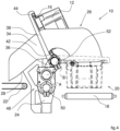
- the first and second guides 42, 44 have a C-shaped cross-section and are configured to engage their respective edges 16 of a box 12 when the box, advancing along the inlet conveyor 18, enters the tipping station 20.
- the first and second guides 42, 44 may have respective inlet sections 46 to facilitate the insertion of the outer edges 16 of a box 12 inside the guides 42, 44.
- the drive unit 48 comprises a first rotary motor 50 carried by the stationary support structure 24 and arranged to control the rotation of the movable support 36 with respect to the stationary support structure 24 around said first axis A.
- the operation of the tipping apparatus 10 is as follows.
- the apparatus 10 is in a pick-up position in which the tipping arms 38 extend above the inlet conveyor 18.
- the first and second guides 42, 44 are at the same distance from the inlet conveyor 18.
- a box 12 containing products 14 advances in the longitudinal direction X along the inlet conveyor 18.
- the outer edges 16 of the box 12 fit into the respective guides 42, 44.
- the movement in the longitudinal direction X of the box 12 stops when the box 12 is located between the two tipping arms 38.
- sensors could be provided which detect the position of the box 12 and stop the inlet conveyor 18 when the box 12 is in the correct position.
- the movable support 36 is driven to rotate about the first axis A in a first direction (counterclockwise in the representation of Figures 2 , 3 and 4 ) and the tipping arms 38 are driven to rotate around the second axis B with respect to the movable support 36 in a second direction opposite to the first direction (clockwise in the representation of Figures 2 , 3 , 4 ).
- This actuation in opposite directions of the movable support 36 and of the tipping arms 38 causes a movement of the tipping arms 38 and of the box 12 along a straight direction C inclined upwards, so as to approach a longitudinal side of the box 12 with the upper edge 30 of the chute 26.
- This approach movement of the box 12 to the upper edge 30 of the chute 26 takes place without tipping the box 12, so as to avoid the risk that the products come out of the box before the box 12 is approached to the chute 26.
- the box 12 When the box 12 reaches the position illustrated with a dashed line in Figure 3 , the box 12 is located between the lateral sides 34 of the chute 26.
- the tipping of the box 12 begins, as shown in Figure 4 .
- the movable support 36 remains stationary and the tipping arms 38 rotate with respect to the movable support 36 around the second axis B.
- the rotation of the tipping arms 38 around the axis B continues until the tipping position shown in Figures 4 and 5 is reached.
- the engagement elements 72, 74 engage the respective guides 66, 68 of the guide plate 64 and are located near the lower ends of the guides 66, 68.
Landscapes
- Engineering & Computer Science (AREA)
- Mechanical Engineering (AREA)
- Discharge Of Articles From Conveyors (AREA)
- Attitude Control For Articles On Conveyors (AREA)
Claims (7)
- Vorrichtung zum Kippen von Behältern, umfassend:- eine stationäre Stützstruktur (24), eine Rutsche (26), die in Bezug auf die stationäre Stützstruktur (24) befestigt ist, und einschließlich einer geneigten Oberfläche (28), die eine Oberkante (30) und eine Unterkante (32) aufweist,- eine bewegliche Stütze (36), die zwei Kipparme (38) trägt, wobei die Kipparme (38) eine erste und eine zweite Führung (42, 44) tragen, die sich parallel zu einer Längsrichtung (X) erstrecken und so konfiguriert sind, dass sie mit jeweiligen Außenkanten (16) einer Kiste (12) in Eingriff stehen, und- eine Antriebseinheit (48), die dazu konfiguriert ist, die Kipparme (38) in Bezug auf die stationäre Stützstruktur (24) entlang einer geraden Richtung (C) zu bewegen, die in Bezug auf eine vertikale Richtung geneigt ist, dadurch gekennzeichnet, dass die Antriebseinheit (48) weiter konfiguriert ist zum Drehen der Kipparme (38) in Bezug auf die stationäre Stützstruktur (24) um eine Achse (A, B), die parallel zur Längsrichtung (X) verläuft,wobei die bewegliche Stütze (36) in Bezug auf die stationäre Stützstruktur (24) um eine erste Achse (A) parallel zur Längsrichtung (X) drehbar ist, und wobei die Kipparme (38) gemeinsam in Bezug auf die bewegliche Stütze (36) um eine zweite Achse (B) drehbar sind, die parallel zur ersten Achse (A) verläuft, und wobei die Antriebseinheit (48) dazu konfiguriert ist, die Drehung der beweglichen Stütze (36) in Bezug auf die stationäre Stützstruktur (24) um die erste Achse (A) und die Drehung der Kipparme (38) in Bezug auf die bewegliche Stütze (36) um die zweite Achse (B) unabhängig voneinander zu steuern,wobei die Antriebseinheit (48) einen ersten Rotationsmotor (50) umfasst, der in Bezug auf die stationäre Stützstruktur (24) befestigt ist und so angeordnet ist, dass er die Drehung der beweglichen Stütze (36) in Bezug auf die stationäre Stützstruktur (24) um die erste Achse (A) steuert, undwobei die Antriebseinheit (48) einen zweiten Rotationsmotor (52) umfasst, der von der beweglichen Stütze (36) getragen wird und so angeordnet ist, dass er die Drehung der Kipparme (38) in Bezug auf die bewegliche Stütze (36) um die zweite Achse (B) steuert.
- Vorrichtung nach Anspruch 1, wobei die Antriebseinheit (48) so gesteuert wird, dass sie die bewegliche Stütze (36) und die Kipparme (38) in zueinander entgegengesetzte Richtungen bewegt, um die Kiste (20) entlang der geraden Richtung (C) bis zu einer Position zu bewegen, wobei eine Oberkante der Kiste (12) an die Oberkante (30) der Rutsche (26) angrenzt.
- Vorrichtung nach Anspruch 1 oder Anspruch 2, wobei die Antriebseinheit (48) so gesteuert wird, dass sie die Drehung der beweglichen Stütze (36) stoppt und die Drehung der Kipparme (38) steuert, um die Kiste (20) um die zweite Achse (B) umzukippen.
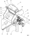
- Vorrichtung zum Kippen von Behältern, umfassend:- eine stationäre Stützstruktur (24),- eine Rutsche (26), die in Bezug auf die stationäre Stützstruktur (24) befestigt ist, und einschließlich einer geneigten Oberfläche (28), die eine Oberkante (30) und eine Unterkante (32) aufweist,- eine bewegliche Stütze (36), die zwei Kipparme (38) trägt, wobei die Kipparme (38) eine erste und eine zweite Führung (42, 44) tragen, die sich parallel zu einer Längsrichtung (X) erstrecken und so konfiguriert sind, dass sie mit jeweiligen Außenkanten (16) einer Kiste (12) in Eingriff stehen, und- eine Antriebseinheit (48), die dazu konfiguriert ist, die Kipparme (38) in Bezug auf die stationäre Stützstruktur (24) entlang einer geraden Richtung (C) zu bewegen, die in Bezug auf eine vertikale Richtung geneigt ist, dadurch gekennzeichnet, dass die Antriebseinheit (48) weiter konfiguriert ist zum Drehen der Kipparme (38) in Bezug auf die stationäre Stützstruktur (24) um eine Achse (A, B), die parallel zur Längsrichtung (X) verläuft,wobei die Kipparme (38) in Bezug auf die bewegliche Stütze (36) befestigt sind, und wobei die Antriebseinheit (48) einen einzelnen Motor (60) umfasst, der von der stationären Stützstruktur (24) getragen wird und mit einem Übertragungsmechanismus (62) verbunden ist, der eine Führungsplatte (64) umfasst, die in Bezug auf die stationäre Stützstruktur (24) befestigt ist und so angeordnet ist, dass sie die bewegliche Stütze (36) entlang der geraden Richtung (C) führt.
- Vorrichtung nach Anspruch 4, wobei der Übertragungsmechanismus (62) einen Arm (76) umfasst, der an einer Ausgangswelle des Motors (60) befestigt ist und an seinem distalen Ende ein drittes Eingriffselement (78) trägt, das in eine dritte Führung (80) eingreift, die in der beweglichen Stütze (36) ausgebildet ist.
- Vorrichtung nach einem der vorstehenden Ansprüche, wobei die Rutsche (26) ein Paar seitlicher Seiten (34) aufweist, die sich auf gegenüberliegenden Seiten der geneigten Oberfläche (28) befinden, und wobei sich die Kipparme (38) in Bezug auf die seitlichen Seiten (34) nach innen erstrecken.
- Vorrichtung nach einem der vorstehenden Ansprüche, umfassend einen Eingangsförderer (18), der zum Vorschieben der Behältern (12) in einer Längsrichtung (X) angeordnet ist, und einen Ausgangsförderer, der zum Vorschieben der aus den Behältern (12) freigegebenen Produkte entlang einer Querrichtung (Y) angeordnet ist, die senkrecht zu der Längsrichtung (X) verläuft.
Applications Claiming Priority (1)
| Application Number | Priority Date | Filing Date | Title |
|---|---|---|---|
| IT102022000016365A IT202200016365A1 (it) | 2022-08-02 | 2022-08-02 | Apparecchio per il ribaltamento di cassette |
Publications (3)
| Publication Number | Publication Date |
|---|---|
| EP4339142A1 EP4339142A1 (de) | 2024-03-20 |
| EP4339142B1 true EP4339142B1 (de) | 2025-04-16 |
| EP4339142C0 EP4339142C0 (de) | 2025-04-16 |
Family
ID=83691058
Family Applications (1)
| Application Number | Title | Priority Date | Filing Date |
|---|---|---|---|
| EP23184777.3A Active EP4339142B1 (de) | 2022-08-02 | 2023-07-11 | Vorrichtung zum kippen von behältern |
Country Status (3)
| Country | Link |
|---|---|
| US (1) | US20240043230A1 (de) |
| EP (1) | EP4339142B1 (de) |
| IT (1) | IT202200016365A1 (de) |
Families Citing this family (2)
| Publication number | Priority date | Publication date | Assignee | Title |
|---|---|---|---|---|
| CN118047201B (zh) * | 2024-04-07 | 2025-03-07 | 池州市千润宇信息技术有限公司 | 一种光伏板加工用的高效输送设备 |
| CN119278762B (zh) * | 2024-12-05 | 2025-02-28 | 辽宁辽拓大益农业机械股份有限公司 | 一种升降式的玉米收割机粮仓结构 |
Family Cites Families (5)
| Publication number | Priority date | Publication date | Assignee | Title |
|---|---|---|---|---|
| US3342358A (en) * | 1965-12-15 | 1967-09-19 | Dempster Brothers Inc | Container dumping devices |
| CN201758718U (zh) * | 2010-09-17 | 2011-03-16 | 嘉兴市瑞邦机械工程有限公司 | 上料机 |
| ES2608409T3 (es) * | 2011-02-16 | 2017-04-10 | Albert Handtmann Maschinenfabrik Gmbh & Co. Kg | Dispositivo y procedimiento para alimentar una máquina que procesa alimentos, en particular una embutidora o una máquina para picar carne con alimentos |
| US11104527B1 (en) | 2019-02-04 | 2021-08-31 | Amazon Technologies, Inc. | Tote flipper |
| CN112849860B (zh) * | 2020-12-31 | 2024-01-05 | 华南理工大学 | 一种倾倒垃圾机械臂和具有倾倒垃圾机械臂的家居机器人 |
-
2022
- 2022-08-02 IT IT102022000016365A patent/IT202200016365A1/it unknown
-
2023
- 2023-07-11 EP EP23184777.3A patent/EP4339142B1/de active Active
- 2023-07-31 US US18/362,304 patent/US20240043230A1/en active Pending
Also Published As
| Publication number | Publication date |
|---|---|
| US20240043230A1 (en) | 2024-02-08 |
| IT202200016365A1 (it) | 2024-02-02 |
| EP4339142C0 (de) | 2025-04-16 |
| EP4339142A1 (de) | 2024-03-20 |
Similar Documents
| Publication | Publication Date | Title |
|---|---|---|
| EP4339142B1 (de) | Vorrichtung zum kippen von behältern | |
| EP2986446B1 (de) | Beutelsammelrobotersystem und verfahren zur montage und sammlung von ungefüllten beutel mit ausguss | |
| US8074431B1 (en) | Hybrid palletizer | |
| US5339606A (en) | Method for accepting continuously supplied products from a production facility and respectively discontinuous delivery of a number of these products at a delivery station | |
| EP2184233A2 (de) | Vorrichtung zum Verpacken von Artikeln und Verfahren dafür | |
| EP3769918B1 (de) | Artikeltransfervorrichtung | |
| CZ286640B6 (cs) | Zařízení pro podávání kusových polotovarů ze zásobníku, zejména obalů | |
| EP1231170A1 (de) | Maschine zur Förderung von leeren Kartondosen | |
| EP1308101A1 (de) | Verfahren und Einheit zum Zuführen von länglichen Elementen | |
| EP3331762B1 (de) | Vorrichtung zum umwickeln von produkten | |
| CN110386295B (zh) | 用于传输泡罩包装的设备及方法 | |
| EP1612147B1 (de) | Vorrichtung zum Transferieren von Gegenständen von einer ersten zu einer zweiten Förderlinie, insbesondere zum Zuführen zu einer Einschachtelmaschine | |
| EP2501633B1 (de) | Rotierender lader für stangenartig angeordnete produkte | |
| EP0569340B1 (de) | Schachtelgreifvorrichtung in einer automatischen Verpackungsmaschine | |
| KR100662928B1 (ko) | 카톤 정립 장치 | |
| CN110386296B (zh) | 用于传输泡罩包装的设备及方法 | |
| US5823738A (en) | Method and unit for forming stacks of articles | |
| CN110386291B (zh) | 用于传输泡罩包装的传输单元及方法 | |
| JPH0818605B2 (ja) | 箱詰製品の段積梱包装置 | |
| US3427779A (en) | Apparatus for packaging articles | |
| JP4229801B2 (ja) | 容器搬送装置 | |
| CN110386292B (zh) | 用于传输泡罩包装的传输单元及方法 | |
| JP4141370B2 (ja) | キャップ巻締装置 | |
| EP4313779B1 (de) | Maschine zum verpacken von produkten der tabakindustrie, insbesondere snus | |
| EP1273539B1 (de) | Verfahren und Anordnung zum Be- und Entladen von Rollcontainern |
Legal Events
| Date | Code | Title | Description |
|---|---|---|---|
| PUAI | Public reference made under article 153(3) epc to a published international application that has entered the european phase |
Free format text: ORIGINAL CODE: 0009012 |
|
| STAA | Information on the status of an ep patent application or granted ep patent |
Free format text: STATUS: THE APPLICATION HAS BEEN PUBLISHED |
|
| AK | Designated contracting states |
Kind code of ref document: A1 Designated state(s): AL AT BE BG CH CY CZ DE DK EE ES FI FR GB GR HR HU IE IS IT LI LT LU LV MC ME MK MT NL NO PL PT RO RS SE SI SK SM TR |
|
| STAA | Information on the status of an ep patent application or granted ep patent |
Free format text: STATUS: REQUEST FOR EXAMINATION WAS MADE |
|
| 17P | Request for examination filed |
Effective date: 20240729 |
|
| RBV | Designated contracting states (corrected) |
Designated state(s): AL AT BE BG CH CY CZ DE DK EE ES FI FR GB GR HR HU IE IS IT LI LT LU LV MC ME MK MT NL NO PL PT RO RS SE SI SK SM TR |
|
| GRAP | Despatch of communication of intention to grant a patent |
Free format text: ORIGINAL CODE: EPIDOSNIGR1 |
|
| STAA | Information on the status of an ep patent application or granted ep patent |
Free format text: STATUS: GRANT OF PATENT IS INTENDED |
|
| RIC1 | Information provided on ipc code assigned before grant |
Ipc: B65G 65/23 20060101AFI20241126BHEP |
|
| INTG | Intention to grant announced |
Effective date: 20241218 |
|
| GRAS | Grant fee paid |
Free format text: ORIGINAL CODE: EPIDOSNIGR3 |
|
| GRAA | (expected) grant |
Free format text: ORIGINAL CODE: 0009210 |
|
| STAA | Information on the status of an ep patent application or granted ep patent |
Free format text: STATUS: THE PATENT HAS BEEN GRANTED |
|
| AK | Designated contracting states |
Kind code of ref document: B1 Designated state(s): AL AT BE BG CH CY CZ DE DK EE ES FI FR GB GR HR HU IE IS IT LI LT LU LV MC ME MK MT NL NO PL PT RO RS SE SI SK SM TR |
|
| REG | Reference to a national code |
Ref country code: GB Ref legal event code: FG4D |
|
| REG | Reference to a national code |
Ref country code: CH Ref legal event code: EP Ref country code: DE Ref legal event code: R096 Ref document number: 602023002918 Country of ref document: DE |
|
| REG | Reference to a national code |
Ref country code: IE Ref legal event code: FG4D |
|
| U01 | Request for unitary effect filed |
Effective date: 20250502 |
|
| U07 | Unitary effect registered |
Designated state(s): AT BE BG DE DK EE FI FR IT LT LU LV MT NL PT RO SE SI Effective date: 20250508 |
|
| U20 | Renewal fee for the european patent with unitary effect paid |
Year of fee payment: 3 Effective date: 20250728 |
|
| PG25 | Lapsed in a contracting state [announced via postgrant information from national office to epo] |
Ref country code: ES Free format text: LAPSE BECAUSE OF FAILURE TO SUBMIT A TRANSLATION OF THE DESCRIPTION OR TO PAY THE FEE WITHIN THE PRESCRIBED TIME-LIMIT Effective date: 20250416 |
|
| PG25 | Lapsed in a contracting state [announced via postgrant information from national office to epo] |
Ref country code: GR Free format text: LAPSE BECAUSE OF FAILURE TO SUBMIT A TRANSLATION OF THE DESCRIPTION OR TO PAY THE FEE WITHIN THE PRESCRIBED TIME-LIMIT Effective date: 20250717 Ref country code: NO Free format text: LAPSE BECAUSE OF FAILURE TO SUBMIT A TRANSLATION OF THE DESCRIPTION OR TO PAY THE FEE WITHIN THE PRESCRIBED TIME-LIMIT Effective date: 20250716 |
|
| PG25 | Lapsed in a contracting state [announced via postgrant information from national office to epo] |
Ref country code: PL Free format text: LAPSE BECAUSE OF FAILURE TO SUBMIT A TRANSLATION OF THE DESCRIPTION OR TO PAY THE FEE WITHIN THE PRESCRIBED TIME-LIMIT Effective date: 20250416 |
|
| PG25 | Lapsed in a contracting state [announced via postgrant information from national office to epo] |
Ref country code: HR Free format text: LAPSE BECAUSE OF FAILURE TO SUBMIT A TRANSLATION OF THE DESCRIPTION OR TO PAY THE FEE WITHIN THE PRESCRIBED TIME-LIMIT Effective date: 20250416 |
|
| PG25 | Lapsed in a contracting state [announced via postgrant information from national office to epo] |
Ref country code: RS Free format text: LAPSE BECAUSE OF FAILURE TO SUBMIT A TRANSLATION OF THE DESCRIPTION OR TO PAY THE FEE WITHIN THE PRESCRIBED TIME-LIMIT Effective date: 20250716 |
|
| PG25 | Lapsed in a contracting state [announced via postgrant information from national office to epo] |
Ref country code: IS Free format text: LAPSE BECAUSE OF FAILURE TO SUBMIT A TRANSLATION OF THE DESCRIPTION OR TO PAY THE FEE WITHIN THE PRESCRIBED TIME-LIMIT Effective date: 20250816 |