EP4313779B1 - Maschine zum verpacken von produkten der tabakindustrie, insbesondere snus - Google Patents
Maschine zum verpacken von produkten der tabakindustrie, insbesondere snus Download PDFInfo
- Publication number
- EP4313779B1 EP4313779B1 EP22711336.2A EP22711336A EP4313779B1 EP 4313779 B1 EP4313779 B1 EP 4313779B1 EP 22711336 A EP22711336 A EP 22711336A EP 4313779 B1 EP4313779 B1 EP 4313779B1
- Authority
- EP
- European Patent Office
- Prior art keywords
- housing
- container
- containers
- closing
- rotor
- Prior art date
- Legal status (The legal status is an assumption and is not a legal conclusion. Google has not performed a legal analysis and makes no representation as to the accuracy of the status listed.)
- Active
Links
Images

Classifications
-
- B—PERFORMING OPERATIONS; TRANSPORTING
- B65—CONVEYING; PACKING; STORING; HANDLING THIN OR FILAMENTARY MATERIAL
- B65B—MACHINES, APPARATUS OR DEVICES FOR, OR METHODS OF, PACKAGING ARTICLES OR MATERIALS; UNPACKING
- B65B35/00—Supplying, feeding, arranging or orientating articles to be packaged
- B65B35/30—Arranging and feeding articles in groups
-
- B—PERFORMING OPERATIONS; TRANSPORTING
- B65—CONVEYING; PACKING; STORING; HANDLING THIN OR FILAMENTARY MATERIAL
- B65B—MACHINES, APPARATUS OR DEVICES FOR, OR METHODS OF, PACKAGING ARTICLES OR MATERIALS; UNPACKING
- B65B35/00—Supplying, feeding, arranging or orientating articles to be packaged
- B65B35/02—Supply magazines
- B65B35/04—Supply magazines with buffer storage devices
-
- B—PERFORMING OPERATIONS; TRANSPORTING
- B65—CONVEYING; PACKING; STORING; HANDLING THIN OR FILAMENTARY MATERIAL
- B65G—TRANSPORT OR STORAGE DEVICES, e.g. CONVEYORS FOR LOADING OR TIPPING, SHOP CONVEYOR SYSTEMS OR PNEUMATIC TUBE CONVEYORS
- B65G65/00—Loading or unloading
- B65G65/23—Devices for tilting and emptying of containers
Definitions
- the present invention relates to a machine (see e.g. DE 10 2019 126522 ) for packaging products of the tobacco industry, particularly snus.
- the object of this solution is to provide a packaging machine capable of transferring the products from the containers into packages being formed inside the machine, without adversely affecting the operating cycle of the machine.
- a preferred embodiment of the solution described here relates to a machine for packaging the products in loose form in sachets or pouches.
- the aforementioned object is achieved by using a packaging machine having the characteristics specified in Claim 1.
- the present invention also relates to a method according to Claim 10.
- the packaging machine described here has been devised for a particular application in which the products to be packaged are fed to the packaging machine inside containers.
- the products to be packaged are arranged in groups corresponding to the groups of products to be packaged in the individual packages.
- the solution described here transfers each group of products from its respective container to a respective pre-formed package.
- the packaging machine described here operates to package the products in loose form in sachets or pouches.
- the machine described here comprises:
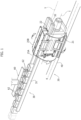
- the overturning unit 20 comprises a rotor 21 comprising a first housing 22, for receiving at least one first container, and a second housing 23 for receiving at least one second container.
- the rotor 21 is rotatable around a horizontal rotation axis I for making the first and the second housing 22, 23 reciprocally swap positions, between a first position P1 for loading the containers 100 and a second position P2 for discharging the products from the containers 100 into the packages 200 that are fed along the feeding direction K.
- the housings 22, 23 are positioned diametrically opposite each other with respect to the axis of rotation I of the rotor.
- the positions P1 and P2 are defined on the same vertical line.
- the second housing 22 is delimited by a bottom 22A and by two lateral abutment parts 22B, which are opposed to each another with respect to the bottom 22A.
- the bottom 22A and the lateral parts 22B extend along a direction parallel to the axis of rotation I.
- the housing 23 has an identical configuration and is, in particular, delimited by a bottom 23A and by two lateral abutment parts 23B.
- the two housings 22, 23 are oriented in opposite directions around the rotation axis I of the rotor so that the housing 22 or 23 that is in position P1 has its lateral parts 22B, 23B above the bottom 22A or 23A, and the housing 23 or 22 that is in position P2 has its lateral abutment parts 23B or 22B below the bottom 23A or 23B.
- the housings 22 and 23 each receive a predetermined group of containers in an arrangement in which the containers rest on the bottom 22A or 23A, with their respective upper openings facing upwards, and are ordered in line along a direction parallel to the axis of rotation I.
- the individual container 100 has an internal wall that divides it into two compartments 100A, 100B, each intended to receive a group of products to be packaged in a respective package 200.
- the internal wall also divides the upper mouth of the container into two separate upper openings 100'A, 100'B.
- the containers 100 are arranged with their respective internal walls parallel to the lateral parts 22B or 23B, so that one of the respective compartments 100A, 100B is positioned nearer to one lateral part of the housing, while the other is positioned nearer to the opposite lateral part.
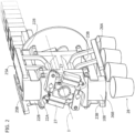
- the overturning unit 20 also comprises closing members 25A, 25B and 26A, 26B associated with the housings 22 and 23 respectively, which perform the function of selectively opening and closing the upper openings 100'A and 100'B of the containers 100 arranged in the housings 22, 23.
- the two closing members 25A, 25B are positioned on opposite sides of the housing 22, outside the lateral parts 22B, and are mounted on the rotor 21 in a pivoting manner about respective axes of rotation parallel to the axis of rotation I.
- Respective actuators 27 drive the two closing members 25A, 25B between a position for closing the containers 100, in which the two members 25A, 25B are placed against or close to the corresponding lateral parts 22B, and an opening position, for discharging the products from the containers 100, in which the two members 25A, 25B are spaced apart from the lateral parts 22B.
- Each closing member comprises a covering body 25' which, in the aforesaid closing position, projects beyond the corresponding lateral part 22B, to close the upper openings 100'A or 100'B of the containers 100; in particular, the covering body 25' of the member 25A closes the upper openings 100'A, which the covering body 25' of the member 25B closes the upper openings 100'B.
- the two closing members 26A, 26B are mounted at the housing 23 in a similar arrangement and have an identical configuration; in the figures, the corresponding covering bodies are indicated by the reference numeral 26'.
- each pair of members 25A, 25B or 26A, 26B is brought to the opening position when the respective housing 22 or 23 is in the loading position P1 for receiving the containers 100.
- the two members 25A, 25B or 26A, 26B are then brought to the closing position, this taking place before the rotor 21 is rotated to swap the positions of the two housings 22, 23.
- the rotor 21 is then rotated to swap the positions of the two housings, bringing the housing 22 or 23 into the discharge position P2.
- the two members 25A, 25B or 26A, 26B are brought back to the opening position individually, at two successive moments, to discharge the products of compartments 100A in a first step, and to discharge the products of compartments 100B in a second step.
- the groups of products discharged during the first step are made to fill respective containers 200 brought to position P2 by the feeding unit 40, and the groups of products discharged in the second step are made to fill further packages 200' which are subsequently fed to position P2 by the feeding unit.
- funnel-like bodies 28 are positioned under the rotor 21 to guide the products in free fall and to ensure that they enter the respective packages 200 or 200'.
- the covering bodies 25' and 26' have an extension such that they project beyond the corresponding lateral part 22B or 23B even in the opening position of the closing member.
- the closing members can support the containers 100 vertically when the housing 22 or 23 is in position P2 and the containers 100 are therefore upside down.
- the packaging machine comprises an inlet channel 31 for bringing the containers 100 containing the products S to the overturning unit 20, and an outlet channel 32 for bringing the empty containers to an outlet of the machine.
- the two channels 31 and 32 form the aforementioned conveyor 30 for making the containers 100 advance along the advance path T.
- the housing 22 or 23 joins the inlet channel and the outlet channel to each other.
- the machine also comprises a drive device 60 for picking the group of containers 100 from the inlet channel and bringing it into the housing 22 or 23.
- the drive device simultaneously removes from said housing the group of empty containers whose products have already been discharged, and releases them into the outlet channel 32.
- the drive device 60 comprises a series of equally spaced engagement members 62, for simultaneously engaging with the containers of the group to be picked, spacing them apart by a predetermined interval F.
- the containers 100 can be positioned inside the housings 22, 23 at the same spacing.
- the interval in question may be determined on the basis of the interval between the upper openings of the packages 200 fed by the feeding unit.
- the packaging machine comprises a control unit 50 capable of operating the actuators and devices described above in a coordinated way, for executing the packaging method described here.
- the control unit 50 is designed to receive a signal W1 indicative of the angular position of the rotor 21, and to cause the closing members 25A, 25B, 26A, 26B to open in accordance with said signal.
- the packaging method comprises the following steps:
- the drive device picks a new group of containers 100 from the inlet channel and brings it into the housing 23 or 22 which is located in position P1.
- the overturning unit 20 may comprise a single closing member associated with each housing 22 or 23, and a single step of discharging the products at position P2 is carried out during operation.
Landscapes
- Engineering & Computer Science (AREA)
- Mechanical Engineering (AREA)
- Manufacture Of Tobacco Products (AREA)
Claims (12)
- Maschine (10) zum Verpacken von Produkten der Tabakindustrie, insbesondere Oraltabak, umfassend:- mindestens einen Förderer (30) zum Zuführen einer Mehrzahl von die Produkte enthaltenden Behältern (100) entlang eines Förderpfads (T);- eine Einheit (40) zum Zuführen von Verpackungen (200) entlang einer Zuführungsrichtung (K); gekennzeichnet durch- eine Kippeinheit (20), die entlang des Förderpfads (T) angeordnet ist und die Folgendes umfasst:- einen Rotor (21), der ein erstes Gehäuse (22) zum Aufnehmen mindestens eines ersten Behälters und ein zweites Gehäuse (23) zum Aufnehmen mindestens eines zweiten Behälters umfasst, wobei der Rotor (21) um eine horizontale Drehachse (I) drehbar ist, um das erste und das zweite Gehäuse (22, 23) zu veranlassen, gegenseitig ihre Positionen zwischen einer ersten Position (P1) zum Beschicken der Behälter und einer zweiten Position (P2) zum Entladen der Produkte aus den Behältern (100) in die Verpackungen (200), die entlang der Zuführungsrichtung (K) zugeführt werden, zu tauschen,- mindestens ein erstes Verschlusselement (25A, 25B) zum Verschließen einer oberen Öffnung (100A', 100B') des in dem ersten Gehäuse (22) positionierten Behälters und mindestens ein zweites Verschlusselement (26A, 26B) zum Verschließen einer oberen Öffnung (100A', 100B') des in dem zweiten Gehäuse (23) positionierten Behälters, wobei das mindestens eine erste Verschlusselement (25A, 25B) und das mindestens eine zweite Verschlusselement (26A, 26B) an dem Rotor (21) derart montiert sind, dass sie zwischen einer Verschlussposition und einer Position zum Öffnen der Behälter beweglich sind, und- eine Steuereinheit (50), die dazu ausgelegt ist, das erste oder das zweite Verschlusselement (25A, 25B, 26A, 26B) in die Öffnungsposition zu steuern, um die Produkte durch die obere Öffnung des Behälters, der in dem ersten oder zweiten Gehäuse (22, 23) positioniert ist, zu entladen, wenn sich das erste oder das zweite Gehäuse (22, 23) in der Entladeposition (P2) befinden.
- Maschine nach Anspruch 1, wobei das erste und das zweite Gehäuse (22, 23) in Bezug auf die Drehachse des Rotors diametral entgegengesetzt zueinander positioniert sind.
- Maschine nach Anspruch 1 oder 2, wobei- das erste Gehäuse (22) durch eine Unterseite (22A) und durch zwei seitliche Widerlagerteile (22B) begrenzt ist, die in Bezug auf die Unterseite entgegengesetzt zueinander sind, wobei sich die Unterseite (22A) und die seitlichen Teile (22B) entlang einer Richtung erstrecken, die parallel zur Drehachse (I) des Rotors ist;- das zweite Gehäuse (23) durch eine Unterseite (23A) und durch zwei seitliche Widerlagerteile (23B) begrenzt ist, die in Bezug auf die Unterseite entgegengesetzt zueinander sind, wobei sich die Unterseite (23A) und die seitlichen Teile (23B) entlang einer Richtung erstrecken, die parallel zur Drehachse (I) des Rotors ist; und- das erste und das zweite Gehäuse (22, 23) in entgegengesetzten Richtungen um die Drehachse (I) des Rotors ausgerichtet sind, so dass sich bei dem ersten oder dem zweiten Gehäuse, das sich in der Beschickungsposition (P1) befindet, die seitlichen Widerlagerteile (22B, 23B) über der Unterseite (22A, 23A) des Gehäuses befinden, und sich bei dem zweiten oder dem ersten Gehäuse, das sich in der Entladeposition (P2) befindet, die seitlichen Widerlagerteile (23B, 22B) über der Unterseite (23A, 22A) des Gehäuses befinden.
- Maschine nach Anspruch 3, wobei jedes des mindestens einen ersten Verschlusselements (25A 25B) und des mindestens einen zweiten Verschlusselements (26A, 26B) auf einer Seite des jeweiligen Fachs (22, 23) positioniert ist und um eine Drehachse schwenken kann, die parallel zur Drehachse (I) des Rotors ist, und wobei jedes des mindestens einen Verschlusselements (25A, 25B) und des mindestens einen zweiten Verschlusselements (26A, 26B) einen Abdeckungskörper (25', 26') umfasst, der über ein entsprechendes seitliches Widerlagerteil des Gehäuses hin zur Innenseite des Gehäuses zum Verschließen der oberen Öffnung des in dem Gehäuse positionierten Behälters hinausragt.
- Maschine nach Anspruch 4, wobei in der Öffnungsposition der Abdeckungskörper (25', 26') weiterhin mit einem Teil davon über den seitlichen Widerlagerteil (22B, 23B) hinausragt, so dass er den in dem Gehäuse positionierten Behälter vertikal stützt.
- Maschine nach Anspruch 3, wobei das mindestens eine erste Verschlusselement zwei Verschlusselemente (25A, 25B) umfasst, die auf entgegengesetzten Seiten des ersten Gehäuses (22) zum gezielten Öffnen und Verschließen entsprechender oberer Öffnungen (100A', 100B') des in dem ersten Gehäuse (22) positionierten Behälters (100) positioniert sind, und wobei das mindestens eine zweite Verschlusselement zwei Verschlusselemente (26A, 26B) umfasst, die auf entgegengesetzten Seiten des zweiten Gehäuses (23) zum gezielten Öffnen und Verschließen jeweiliger oberer Öffnungen (100A', 100B') des in dem zweiten Gehäuse (23) positionierten Behälters (100) positioniert sind.
- Maschine nach Anspruch 3, wobei der mindestens eine Förderer (30) einen Einlaufkanal (31) zum Bringen der die Produkte enthaltenden Behälter zu der Kippeinheit (20) und einen Auslaufkanal (32) zum Bringen der leeren Behälter zu einem Auslauf der Maschine umfasst, wobei in der Beschickungsposition (P1) das erste oder das zweite Gehäuse (22, 23) den Einlaufkanal (31) und den Auslaufkanal (32) miteinander verbindet, und wobei die Maschine eine Ziehvorrichtung (60) zum Bringen mindestens eines Behälters, der sich in dem Einlaufkanal (31) befindet, zu dem ersten oder dem zweiten Gehäuse (22, 23) der Kippeinheit (20) und zeitgleich mindestens eines in dem ersten oder dem zweiten Gehäuse (22, 23) positionierten Behälters zu dem Auslaufkanal (32) umfasst.
- Maschine nach Anspruch 7, wobei das erste und das zweite Gehäuse (22, 23) der Kippeinheit (20) jeweils eine derartige Länge entlang der Drehachse (I) des Rotors aufweisen, dass es eine vorbestimmte Anzahl an Behältern unterbringen kann, und wobei die Ziehvorrichtung (60) eine Reihe von gleichmäßig voneinander beabstandeten Eingriffselementen (62) zum zeitgleichen Ineingriffbringen einer Anzahl an Behältern, die gleich der vorbestimmten Anzahl ist, umfasst, wobei sie in einem Abstand eines vorgegebenen Abstandsmaßes voneinander gehalten werden.
- Maschine nach einem der vorhergehenden Ansprüche, umfassend eine Einheit zum Abgeben einer vorbestimmten Menge an Wasser in die Verpackungen (200), in die die Produkte entladen wurden.
- Verfahren zum Verpacken von Produkten (S), die in Behältern zu einer Verpackungsmaschine transportiert werden,
umfassend die folgenden Schritte:- an einer Position (P1) zum Beschicken der Behälter, Aufnehmen mindestens eines ersten Produkte enthaltenden Behälters in einem ersten Gehäuse (22), das in einem Rotor (21) einer Kippeinheit (20) hergestellt ist, der sich um eine horizontale Drehachse (I) drehen kann;- Drehen des Rotors (21) um die Drehachse (I), bis das erste Gehäuse (22) in eine Position (P2) zum Entladen der Produkte aus den Behältern gebracht wurde, und zeitgleich Bringen eines zweiten in dem Rotor (21) bereitgestellten Gehäuses (23) in die Position (P1) zum Beschicken der Behälter;- Zuführen einer oder mehrerer Verpackungen (200), vorzugsweise Beutel, zu einem Bereich unterhalb der Entladeposition (P2);- Antreiben eines ersten Elements (25A, 25B) zum Verschließen der Behälter, das mit dem ersten Gehäuse (22) assoziiert ist, von einer Verschlussposition in eine Öffnungsposition, um die Produkte durch eine obere Öffnung (100A', 100B') des mindestens einen in dem ersten Gehäuse (22) positionierten ersten Behälters in eine oder mehrere darunterliegende Verpackungen (200) zu entladen;- an der Beschickungsposition (P1), Aufnehmen mindestens eines zweiten Produkte enthaltenden Behälters in dem zweiten Gehäuse (23) des Rotors (21);- Drehen des Rotors (21) um die Drehachse (I), um das erste und das zweite Gehäuse (22, 23) zu veranlassen, ihre Positionen zu tauschen, um das erste Gehäuse (22) und den mindestens einen ersten Behälter, leer, in die Beschickungsposition (P1) und das zweite Gehäuse (23) und den mindestens einen zweiten, die Produkte enthaltenden Behälter in die Entladeposition (P2) zu bringen;- Zuführen einer neuen Verpackung oder neuer Verpackungen (200') in den Bereich unterhalb der Entladeposition (P1);- Antreiben eines zweiten Elements (26A, 26B) zum Verschließen der Behälter, das mit dem zweiten Gehäuse (23) assoziiert ist, von einer Verschlussposition in eine Öffnungsposition, um die Produkte durch eine obere Öffnung (100A', 100B') des mindestens einen in dem zweiten Gehäuse (23) positionierten zweiten Behälters in eine neue darunterliegende Verpackung oder neue darunterliegende Verpackungen (200; 200') zu entladen. - Verfahren nach Anspruch 10, wobei- das erste Gehäuse (22) durch eine Unterseite (22A) und durch zwei seitliche Widerlagerteile (22B) begrenzt ist, die in Bezug auf die Unterseite (22A) entgegengesetzt zueinander sind;- das zweite Gehäuse (23) durch eine Unterseite (23A) und durch zwei seitliche Widerlagerteile (23B) begrenzt ist, die in Bezug auf die Unterseite (23A) entgegengesetzt zueinander sind; und- der Schritt zum Aufnehmen mindestens eines ersten Behälters in einem ersten Gehäuse (22) oder Aufnehmen mindestens eines zweiten Behälters in einem zweiten Gehäuse (23) Bringen, mittels einer Ziehvorrichtung (60), des mindestens einen ersten oder zweiten Behälters von einem Einlaufkanal (31) stromaufwärts der Kippeinheit (20) in das erste oder das zweite Gehäuse (22, 23), und zeitgleich Bringen mindestens eines leeren Behälters, der in dem ersten oder dem zweiten Gehäuse (22, 23) positioniert ist, zu einem Auslaufkanal (32) stromabwärts der Kippeinheit (20) umfasst.
- Verfahren nach Anspruch 11, wobei der Schritt zum Bringen mindestens eines oder zweiten Behälters von einem Einlaufkanal (31) stromaufwärts der Kippeinheit (20) in das erste oder das zweite Gehäuse (22, 23) Bringen einer vorbestimmten Anzahl an Behältern in das erste oder das zweite Gehäuse (22, 23) umfasst, und der Schritt zum Bringen eines leeren Behälters, der in dem ersten oder dem zweiten Gehäuse (22, 23) positioniert ist, zu einem Auslaufkanal (32) Bringen einer Anzahl von Behältern, die gleich der vorbestimmten Anzahl ist, zu dem Auslaufkanal (32) umfasst.
Applications Claiming Priority (2)
| Application Number | Priority Date | Filing Date | Title |
|---|---|---|---|
| IT102021000007430A IT202100007430A1 (it) | 2021-03-26 | 2021-03-26 | Macchina per il confezionamento di prodotti dell'industria del tabacco, in particolare snus |
| PCT/IB2022/052434 WO2022200942A1 (en) | 2021-03-26 | 2022-03-17 | Machine for packaging products of the tobacco industry, particularly snus |
Publications (2)
| Publication Number | Publication Date |
|---|---|
| EP4313779A1 EP4313779A1 (de) | 2024-02-07 |
| EP4313779B1 true EP4313779B1 (de) | 2024-12-11 |
Family
ID=76375524
Family Applications (1)
| Application Number | Title | Priority Date | Filing Date |
|---|---|---|---|
| EP22711336.2A Active EP4313779B1 (de) | 2021-03-26 | 2022-03-17 | Maschine zum verpacken von produkten der tabakindustrie, insbesondere snus |
Country Status (4)
| Country | Link |
|---|---|
| EP (1) | EP4313779B1 (de) |
| IT (1) | IT202100007430A1 (de) |
| PL (1) | PL4313779T3 (de) |
| WO (1) | WO2022200942A1 (de) |
Family Cites Families (2)
| Publication number | Priority date | Publication date | Assignee | Title |
|---|---|---|---|---|
| FR2950614A1 (fr) * | 2009-09-29 | 2011-04-01 | Chayoux | Chaine de dechargement de palettes |
| IT201800009078A1 (it) * | 2018-10-02 | 2020-04-02 | Ima Industria Macch Automatiche Spa | Metodo per confezionare articoli, e relativa macchina di confezionamento. |
-
2021
- 2021-03-26 IT IT102021000007430A patent/IT202100007430A1/it unknown
-
2022
- 2022-03-17 WO PCT/IB2022/052434 patent/WO2022200942A1/en not_active Ceased
- 2022-03-17 PL PL22711336.2T patent/PL4313779T3/pl unknown
- 2022-03-17 EP EP22711336.2A patent/EP4313779B1/de active Active
Also Published As
| Publication number | Publication date |
|---|---|
| EP4313779A1 (de) | 2024-02-07 |
| WO2022200942A1 (en) | 2022-09-29 |
| IT202100007430A1 (it) | 2022-09-26 |
| PL4313779T3 (pl) | 2025-03-10 |
Similar Documents
| Publication | Publication Date | Title |
|---|---|---|
| EP2184233A2 (de) | Vorrichtung zum Verpacken von Artikeln und Verfahren dafür | |
| EP1602583B1 (de) | Einheit für die Übergabe von Produkten von einer Verpackungsmaschine zur Verschachtelung | |
| US7497064B2 (en) | Vertical cartoner | |
| US7191892B2 (en) | Apparatus for transferring products from a first conveying line to a second conveying line, in particular for feeding a boxing machine | |
| EP2457551B1 (de) | Transferlinie | |
| KR102866027B1 (ko) | 제약 물품들을 카운트하고 물품들을 병들의 내부에 삽입하기 위한 카운터-충전 장치 | |
| KR100374238B1 (ko) | 외부 컨테이너로 용기를 삽입하기 위한 장치 및 상기 장치의 작동방법 | |
| EP1852354B1 (de) | Verfahren und Vorrichtung zum automatischen Sortieren und/oder Verpacken von länglichen Produkten | |
| CN108216748B (zh) | 投入机 | |
| US8448775B2 (en) | Rotatory slug loader | |
| EP4313779B1 (de) | Maschine zum verpacken von produkten der tabakindustrie, insbesondere snus | |
| EP4339142A1 (de) | Vorrichtung zum kippen von behältern | |
| JPS5847220A (ja) | 自動計量装置 | |
| US20240417119A1 (en) | Method and apparatus for feeding products of the tobacco industry, particularly snus, from a production machine to a packaging machine | |
| EP2700914B1 (de) | Mehrkopf-Kombinationswaage | |
| CN108652075A (zh) | 清空填充有烟草业的棒状物品的托盘的方法 | |
| JPH05170206A (ja) | 荷作り装置 | |
| KR20220086564A (ko) | 패키징 기계의 유출구로부터 박싱 기계로의 공급을 위해 연속적으로 활성화된 컨베이어 수단으로 스틱팩들을 이송하기 위한 방법, 및 스틱팩들의 이송 스테이션 | |
| CN222224644U (zh) | 槟榔包装线 | |
| JP2003054517A (ja) | ボックスケーサ | |
| JP2002302106A (ja) | 被包装製品の運搬制御方法及び装置 | |
| KR20240006570A (ko) | 소정의 수의 약학 물품으로써 병을 충전하기 위한 방법 및 상기 방법을 실행하기 위한 기기 | |
| CN118458070A (zh) | 槟榔送料装置及槟榔包装设备 | |
| JP2005225504A (ja) | 袋詰め包装機用製品搬出装置 | |
| JPH11116044A (ja) | 袋詰め包装品の振分け移載装置 |
Legal Events
| Date | Code | Title | Description |
|---|---|---|---|
| STAA | Information on the status of an ep patent application or granted ep patent |
Free format text: STATUS: UNKNOWN |
|
| STAA | Information on the status of an ep patent application or granted ep patent |
Free format text: STATUS: THE INTERNATIONAL PUBLICATION HAS BEEN MADE |
|
| PUAI | Public reference made under article 153(3) epc to a published international application that has entered the european phase |
Free format text: ORIGINAL CODE: 0009012 |
|
| STAA | Information on the status of an ep patent application or granted ep patent |
Free format text: STATUS: REQUEST FOR EXAMINATION WAS MADE |
|
| 17P | Request for examination filed |
Effective date: 20231009 |
|
| AK | Designated contracting states |
Kind code of ref document: A1 Designated state(s): AL AT BE BG CH CY CZ DE DK EE ES FI FR GB GR HR HU IE IS IT LI LT LU LV MC MK MT NL NO PL PT RO RS SE SI SK SM TR |
|
| P01 | Opt-out of the competence of the unified patent court (upc) registered |
Effective date: 20240408 |
|
| DAV | Request for validation of the european patent (deleted) | ||
| DAX | Request for extension of the european patent (deleted) | ||
| GRAP | Despatch of communication of intention to grant a patent |
Free format text: ORIGINAL CODE: EPIDOSNIGR1 |
|
| STAA | Information on the status of an ep patent application or granted ep patent |
Free format text: STATUS: GRANT OF PATENT IS INTENDED |
|
| INTG | Intention to grant announced |
Effective date: 20240806 |
|
| GRAS | Grant fee paid |
Free format text: ORIGINAL CODE: EPIDOSNIGR3 |
|
| GRAA | (expected) grant |
Free format text: ORIGINAL CODE: 0009210 |
|
| STAA | Information on the status of an ep patent application or granted ep patent |
Free format text: STATUS: THE PATENT HAS BEEN GRANTED |
|
| AK | Designated contracting states |
Kind code of ref document: B1 Designated state(s): AL AT BE BG CH CY CZ DE DK EE ES FI FR GB GR HR HU IE IS IT LI LT LU LV MC MK MT NL NO PL PT RO RS SE SI SK SM TR |
|
| REG | Reference to a national code |
Ref country code: GB Ref legal event code: FG4D |
|
| REG | Reference to a national code |
Ref country code: CH Ref legal event code: EP |
|
| REG | Reference to a national code |
Ref country code: IE Ref legal event code: FG4D |
|
| REG | Reference to a national code |
Ref country code: DE Ref legal event code: R096 Ref document number: 602022008632 Country of ref document: DE |
|
| REG | Reference to a national code |
Ref country code: NL Ref legal event code: FP |
|
| REG | Reference to a national code |
Ref country code: LT Ref legal event code: MG9D |
|
| PG25 | Lapsed in a contracting state [announced via postgrant information from national office to epo] |
Ref country code: HR Free format text: LAPSE BECAUSE OF FAILURE TO SUBMIT A TRANSLATION OF THE DESCRIPTION OR TO PAY THE FEE WITHIN THE PRESCRIBED TIME-LIMIT Effective date: 20241211 |
|
| PGFP | Annual fee paid to national office [announced via postgrant information from national office to epo] |
Ref country code: DE Payment date: 20250327 Year of fee payment: 4 |
|
| PG25 | Lapsed in a contracting state [announced via postgrant information from national office to epo] |
Ref country code: FI Free format text: LAPSE BECAUSE OF FAILURE TO SUBMIT A TRANSLATION OF THE DESCRIPTION OR TO PAY THE FEE WITHIN THE PRESCRIBED TIME-LIMIT Effective date: 20241211 |
|
| PGFP | Annual fee paid to national office [announced via postgrant information from national office to epo] |
Ref country code: NL Payment date: 20250319 Year of fee payment: 4 |
|
| PG25 | Lapsed in a contracting state [announced via postgrant information from national office to epo] |
Ref country code: BG Free format text: LAPSE BECAUSE OF FAILURE TO SUBMIT A TRANSLATION OF THE DESCRIPTION OR TO PAY THE FEE WITHIN THE PRESCRIBED TIME-LIMIT Effective date: 20241211 |
|
| PG25 | Lapsed in a contracting state [announced via postgrant information from national office to epo] |
Ref country code: ES Free format text: LAPSE BECAUSE OF FAILURE TO SUBMIT A TRANSLATION OF THE DESCRIPTION OR TO PAY THE FEE WITHIN THE PRESCRIBED TIME-LIMIT Effective date: 20241211 |
|
| PG25 | Lapsed in a contracting state [announced via postgrant information from national office to epo] |
Ref country code: NO Free format text: LAPSE BECAUSE OF FAILURE TO SUBMIT A TRANSLATION OF THE DESCRIPTION OR TO PAY THE FEE WITHIN THE PRESCRIBED TIME-LIMIT Effective date: 20250311 |
|
| PG25 | Lapsed in a contracting state [announced via postgrant information from national office to epo] |
Ref country code: LV Free format text: LAPSE BECAUSE OF FAILURE TO SUBMIT A TRANSLATION OF THE DESCRIPTION OR TO PAY THE FEE WITHIN THE PRESCRIBED TIME-LIMIT Effective date: 20241211 Ref country code: GR Free format text: LAPSE BECAUSE OF FAILURE TO SUBMIT A TRANSLATION OF THE DESCRIPTION OR TO PAY THE FEE WITHIN THE PRESCRIBED TIME-LIMIT Effective date: 20250312 |
|
| PGFP | Annual fee paid to national office [announced via postgrant information from national office to epo] |
Ref country code: PL Payment date: 20250121 Year of fee payment: 4 |
|
| PG25 | Lapsed in a contracting state [announced via postgrant information from national office to epo] |
Ref country code: RS Free format text: LAPSE BECAUSE OF FAILURE TO SUBMIT A TRANSLATION OF THE DESCRIPTION OR TO PAY THE FEE WITHIN THE PRESCRIBED TIME-LIMIT Effective date: 20250311 |
|
| REG | Reference to a national code |
Ref country code: AT Ref legal event code: MK05 Ref document number: 1750227 Country of ref document: AT Kind code of ref document: T Effective date: 20241211 |
|
| PG25 | Lapsed in a contracting state [announced via postgrant information from national office to epo] |
Ref country code: SM Free format text: LAPSE BECAUSE OF FAILURE TO SUBMIT A TRANSLATION OF THE DESCRIPTION OR TO PAY THE FEE WITHIN THE PRESCRIBED TIME-LIMIT Effective date: 20241211 |
|
| PG25 | Lapsed in a contracting state [announced via postgrant information from national office to epo] |
Ref country code: IS Free format text: LAPSE BECAUSE OF FAILURE TO SUBMIT A TRANSLATION OF THE DESCRIPTION OR TO PAY THE FEE WITHIN THE PRESCRIBED TIME-LIMIT Effective date: 20250411 |
|
| PG25 | Lapsed in a contracting state [announced via postgrant information from national office to epo] |
Ref country code: PT Free format text: LAPSE BECAUSE OF FAILURE TO SUBMIT A TRANSLATION OF THE DESCRIPTION OR TO PAY THE FEE WITHIN THE PRESCRIBED TIME-LIMIT Effective date: 20250411 |
|
| PG25 | Lapsed in a contracting state [announced via postgrant information from national office to epo] |
Ref country code: EE Free format text: LAPSE BECAUSE OF FAILURE TO SUBMIT A TRANSLATION OF THE DESCRIPTION OR TO PAY THE FEE WITHIN THE PRESCRIBED TIME-LIMIT Effective date: 20241211 |
|
| PG25 | Lapsed in a contracting state [announced via postgrant information from national office to epo] |
Ref country code: RO Free format text: LAPSE BECAUSE OF FAILURE TO SUBMIT A TRANSLATION OF THE DESCRIPTION OR TO PAY THE FEE WITHIN THE PRESCRIBED TIME-LIMIT Effective date: 20241211 Ref country code: AT Free format text: LAPSE BECAUSE OF FAILURE TO SUBMIT A TRANSLATION OF THE DESCRIPTION OR TO PAY THE FEE WITHIN THE PRESCRIBED TIME-LIMIT Effective date: 20241211 |
|
| PG25 | Lapsed in a contracting state [announced via postgrant information from national office to epo] |
Ref country code: SK Free format text: LAPSE BECAUSE OF FAILURE TO SUBMIT A TRANSLATION OF THE DESCRIPTION OR TO PAY THE FEE WITHIN THE PRESCRIBED TIME-LIMIT Effective date: 20241211 |
|
| PG25 | Lapsed in a contracting state [announced via postgrant information from national office to epo] |
Ref country code: CZ Free format text: LAPSE BECAUSE OF FAILURE TO SUBMIT A TRANSLATION OF THE DESCRIPTION OR TO PAY THE FEE WITHIN THE PRESCRIBED TIME-LIMIT Effective date: 20241211 |
|
| PG25 | Lapsed in a contracting state [announced via postgrant information from national office to epo] |
Ref country code: IT Free format text: LAPSE BECAUSE OF FAILURE TO SUBMIT A TRANSLATION OF THE DESCRIPTION OR TO PAY THE FEE WITHIN THE PRESCRIBED TIME-LIMIT Effective date: 20241211 |
|
| PG25 | Lapsed in a contracting state [announced via postgrant information from national office to epo] |
Ref country code: SE Free format text: LAPSE BECAUSE OF FAILURE TO SUBMIT A TRANSLATION OF THE DESCRIPTION OR TO PAY THE FEE WITHIN THE PRESCRIBED TIME-LIMIT Effective date: 20241211 |
|
| REG | Reference to a national code |
Ref country code: DE Ref legal event code: R097 Ref document number: 602022008632 Country of ref document: DE |
|
| PG25 | Lapsed in a contracting state [announced via postgrant information from national office to epo] |
Ref country code: DK Free format text: LAPSE BECAUSE OF FAILURE TO SUBMIT A TRANSLATION OF THE DESCRIPTION OR TO PAY THE FEE WITHIN THE PRESCRIBED TIME-LIMIT Effective date: 20241211 |
|
| PG25 | Lapsed in a contracting state [announced via postgrant information from national office to epo] |
Ref country code: MC Free format text: LAPSE BECAUSE OF FAILURE TO SUBMIT A TRANSLATION OF THE DESCRIPTION OR TO PAY THE FEE WITHIN THE PRESCRIBED TIME-LIMIT Effective date: 20241211 |
|
| PLBE | No opposition filed within time limit |
Free format text: ORIGINAL CODE: 0009261 |
|
| STAA | Information on the status of an ep patent application or granted ep patent |
Free format text: STATUS: NO OPPOSITION FILED WITHIN TIME LIMIT |
|
| REG | Reference to a national code |
Ref country code: CH Ref legal event code: L10 Free format text: ST27 STATUS EVENT CODE: U-0-0-L10-L00 (AS PROVIDED BY THE NATIONAL OFFICE) Effective date: 20251022 |
|
| REG | Reference to a national code |
Ref country code: CH Ref legal event code: H13 Free format text: ST27 STATUS EVENT CODE: U-0-0-H10-H13 (AS PROVIDED BY THE NATIONAL OFFICE) Effective date: 20251023 |
|
| PG25 | Lapsed in a contracting state [announced via postgrant information from national office to epo] |
Ref country code: LU Free format text: LAPSE BECAUSE OF NON-PAYMENT OF DUE FEES Effective date: 20250317 |
|
| 26N | No opposition filed |
Effective date: 20250912 |