EP4339060B1 - Tête d'attelage à accouplement automatique de type scharfenberg - Google Patents
Tête d'attelage à accouplement automatique de type scharfenberg Download PDFInfo
- Publication number
- EP4339060B1 EP4339060B1 EP23197197.9A EP23197197A EP4339060B1 EP 4339060 B1 EP4339060 B1 EP 4339060B1 EP 23197197 A EP23197197 A EP 23197197A EP 4339060 B1 EP4339060 B1 EP 4339060B1
- Authority
- EP
- European Patent Office
- Prior art keywords
- coupling
- triple
- shaft gear
- component
- output
- Prior art date
- Legal status (The legal status is an assumption and is not a legal conclusion. Google has not performed a legal analysis and makes no representation as to the accuracy of the status listed.)
- Active
Links
Images


Classifications
-
- B—PERFORMING OPERATIONS; TRANSPORTING
- B61—RAILWAYS
- B61G—COUPLINGS; DRAUGHT AND BUFFING APPLIANCES
- B61G3/00—Couplings comprising mating parts of similar shape or form which can be coupled without the use of any additional element or elements
- B61G3/16—Couplings comprising mating parts of similar shape or form which can be coupled without the use of any additional element or elements with coupling heads rigidly connected by rotatable hook plates or discs and balancing links, the coupling members forming a parallelogram, e.g. "Scharfenberg" type
- B61G3/20—Control devices, e.g. for uncoupling
Definitions
- the invention relates to a coupling head for an automatic coupling, in particular for a Scharfenberg coupling, wherein the coupling head has a coupling component which is mounted rotatably about a main axis of rotation and which is designed to cooperate with a coupling rod of another, in particular identical, coupling head, and wherein the coupling head has a coupling rod (3) which is pivotally connected to the coupling component and is designed to cooperate with a coupling component of the other coupling head.
- a central buffer coupling also known as a Scharfenberg coupling
- the Scharfenberg coupling is used to automatically couple two rail vehicles together. It consists of two identical coupling heads that can be automatically coupled by bringing them closer together until a stop is reached. Each of the two coupling heads contains a coupling component that is rotatably mounted about a main axis of rotation and is usually designed as a hook disc.
- the end of a coupling rod, in particular an eye rod is pivotally attached to the rotatably mounted coupling component by means of a swivel joint, with the swivel axis of the swivel joint being aligned parallel to the main axis of rotation of the coupling component.
- each of the eye rods can have a so-called eye cylinder at its free end, with each of the coupling components also having a hook mouth opposite the swivel joint with respect to the main axis of rotation for receiving the eye cylinder of the other eye rod.
- the coupling component is designed as a hook disc, the hook mouth is usually located on its peripheral edge.
- the two eye cylinders engage in the hook mouths, with the coupling components in a locked rotational position.
- the Rotatably mounted coupling components are each rotated around their main axis of rotation until a release rotation position is reached, until the eyelet cylinders can be removed from the hook mouths.
- the train coupling has a coupling head that includes a coupling head housing and a coupling lock with a locking mechanism.
- the coupling lock is designed as a rotary lock with a coupling eye and a frog, wherein the frog is rotatable about a main axis between a coupled position and an uncoupled position and wherein the coupling eye is connected to the frog with a first end that can be rotated about a coupling eye axis.
- the frog has a mouth that is arranged to receive a second end of a coupling eye of an oppositely identical coupling head.
- An electrically operated uncoupling device comprises an electric motor that is at least indirectly connected to the frog via a drive connection in order to rotate the frog from the coupled position into the uncoupled position.
- the electric motor has an output rotation axis that is arranged at least substantially radially to the main axis.
- an angular gear is provided, which consists of a drive pinion and a crown gear or bevel gear meshing with it, the axis of rotation of which is parallel to the main axis.
- a similar train coupling is made of DE 10 2021 132991 A1 known.
- a coupling head of the type mentioned at the outset which is characterized in that the coupling head comprises an actuator with an electric drive motor and with a electric drive motor has a three-shaft gearbox connected downstream of the drive motor, the output of which is coupled to the coupling component in order to release the coupling component from a coupling rotational position and/or to rotate it into a release rotational position by a motor as required, wherein the rotational axis of the rotor of the drive motor and/or the rotational axis of the three-shaft gearbox is/are aligned parallel or coaxially to the main rotational axis of the coupling component.
- the coupling component can, in particular, be designed as a hook disc. However, it is also possible for the coupling component to be designed differently.
- the coupling component can be a rotatably mounted component on which a coupling rod is articulated and which has a coupling element, in particular a receptacle for a counter-coupling element, for example, an eyelet cylinder, of the coupling rod of another coupling head.
- the output of the three-shaft gearbox can be A spur gear can be coupled to the coupling component.
- an output shaft of the three-shaft gear can have external gearing that meshes with external gearing of the coupling component.
- a circular spline or a dynamic spline of the stress wave gear can advantageously function as the output and have external gearing for coupling to the coupling component.
- the output of the three-shaft gearbox carries the coupling component.
- This design eliminates the need for a transmission gear connected between the output of the three-shaft gearbox and the coupling component.
- a rotary bearing of the output of the three-shaft gearbox functions as a pivot bearing for the coupling component.
- a three-shaft transmission is understood, in particular, to be a transmission having three shafts, each of which functions either as a drive shaft, an output shaft, or as a fixed shaft (for example, relative to a frame or a housing of the three-shaft transmission).
- the three-shaft transmission can be designed as a tension shaft transmission having a circular spline, a flex spline, and a shaft generator, wherein the tension shaft transmission can be operated, for example, in such a way that the shaft generator functions as the drive shaft, the flex spline as the output shaft, and the circular spline as the fixed shaft (for example, fixed to the housing or frame).
- the three-shaft transmission can alternatively be designed as a planetary transmission, in which, for example, the sun gear functions as the drive shaft and the ring gear as the output shaft, while the planet carrier functions as the fixed shaft (for example, fixed to the housing or frame).
- a three-shaft gearbox can also be operated as a summing gearbox, with two of the shafts acting as input shafts and one of the three shafts as the output shaft.
- a three-shaft gearbox can also be operated as a transfer case, with two of the shafts acting as output shafts and one of the three shafts acting as the input shaft.
- a two-shaft gearbox has one shaft acting as the input shaft and one as the output shaft, with no third shaft coupled to the other two shafts and acting as the input shaft, output shaft or fixed shaft.
- bevel gear gearboxes also called angle gearboxes
- the coupling head has a freewheel.
- the freewheel can advantageously be arranged such that it decouples the actuator from a rotation of the coupling component during a coupling process.
- the freewheel can be designed and arranged such that the gear is not driven back by a coupling process and/or that the rotor of the drive motor is not rotated by a coupling process.
- the actuator is decoupled from the hook disc by means of the freewheel, and the coupling component can be rotated unhindered (for example, driven by a spring device or by the coupling rod of the other coupling head inserting into the coupling head) into the locking rotational position when needed, in particular before or during a coupling process.
- the output of the three-shaft gearbox can be coupled to the coupling component via the freewheel.
- the freewheel can be connected between the output of the three-shaft gearbox and the coupling component to decouple the drive motor and the three-shaft gearbox.
- the output of the three-shaft gearbox can include the freewheel.
- the freewheel can also be arranged such that when the coupling component is transferred from the release rotational position to the coupling rotational position (for example, driven by a spring device or by the coupling rod of the other coupling head inserting into the coupling head), it decouples the electric drive motor, but not the three-shaft gearbox, from any rotational movement of the coupling component.
- the coupling component rotating into the coupling rotational position only drives back the three-shaft gearbox, but not the drive motor.
- the freewheel can be connected between the electric drive motor and the three-shaft gearbox.
- the drive motor is arranged coaxially with the three-shaft gearbox.
- the drive motor can have an output shaft that is rigidly connected to a drive shaft of the three-shaft gearbox.
- an output shaft of the drive motor and a drive shaft of the three-shaft gearbox are manufactured together in one piece from the same piece of raw material.
- the drive motor is arranged axially parallel to the three-shaft transmission.
- a traction drive in particular a belt drive, can be present, which transmits torque from an output component of the drive motor, for example, an output shaft, to a drive component of the three-shaft transmission.
- the coupling head preferably has a housing that encloses at least the coupling component.
- the housing also encloses the actuator at least partially, in particular completely. In this way, the actuator is particularly well protected against damage and contamination.
- the entire actuator or at least part of the actuator outside the housing.
- the drive motor can be arranged outside the housing, while the three-shaft gear is arranged inside the housing.
- Such a design has the particular advantage that the drive motor is easily accessible, for example for maintenance work, and that electrical cables for supplying the drive motor with energy and/or for controlling the drive motor do not have to be laid into the housing of the coupling head.
- At least one component of the actuator is connected to the housing in a rotationally fixed manner.
- at least one component of the actuator is fastened, in particular directly, to the housing in a rotationally fixed manner.
- the three-shaft gear unit can be constructed in such a way that one of the shafts of the three-shaft gear unit is rotatably mounted relative to another shaft of the three-shaft gear unit.
- the gear unit can, for example, be a stress wave gear unit in which a circular spline is rotatably mounted relative to a flex spline or relative to a drive shaft connected to a wave generator by means of the rolling element bearing.
- the stress wave gear unit can be designed as a ring gear unit.
- the circular spline can, for example, be rotatably mounted relative to a dynamic spline by means of the rolling element bearing.
- the rolling element bearing can, in particular, be an output bearing of the three-shaft gear unit.
- the three-shaft gearbox can advantageously have a hollow drive shaft. This allows, for example, an output shaft of the three-shaft gearbox to run through the drive shaft, thus achieving a compact design.
- the three-shaft gearbox can advantageously have an Oldham coupling.
- the drive motor can be coupled to the three-shaft gearbox via the Oldham coupling.
- the Oldham coupling can serve to compensate for an axial offset and/or to decouple the three-shaft gearbox and the drive motor from each other with regard to radial movements.
- the three-shaft gear can be a stress wave gear.
- the stress wave gear can be designed, in particular, as a pot gear or a hat gear.
- the stress wave transmission can be designed as a ring transmission.
- a circular spline or a dynamic spline of the stress wave transmission forms the output or is part of the output.
- a flex spline of the stress wave transmission can form the output or be part of the output.
- the gear unit may advantageously be a cycloidal gear unit or a planetary gear unit, for example.
- an automatic coupling in particular a Scharfenberg coupling, which has two, in particular identical, coupling heads according to the invention that can be coupled to one another.
- a coupling state of the coupling heads can be released remotely by means of the actuator.
- the coupling component of at least one of the coupling heads is rotated into the release rotational position to release the coupling connection. In this position, the coupling rods are released from the coupling components, so that the coupling heads can be spatially separated from one another.
- a vehicle in particular a rail vehicle, for example a wagon or a locomotive, which has at least one coupling head according to the invention, preferably two coupling heads according to the invention.
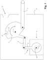
- Fig. 1 shows a first embodiment of a coupling head according to the invention.
- the coupling head has a coupling component 2 rotatably mounted about a main axis of rotation 1 (running perpendicular to the plane of the drawing), which coupling component is designed to interact with a coupling rod 3 of another, in particular identical, coupling head (not shown in this figure).
- the coupling head also has a coupling rod 3 pivotably connected to the coupling component 2, which coupling rod is designed to interact with a coupling component 2 of the other (not shown) coupling head.
- the coupling head has an actuator 4 with an electric drive motor 5 (not explicitly shown in this figure) and with a electric drive motor 5 has a three-shaft gearbox 6 (not explicitly shown in this figure) connected downstream of it.
- the three-shaft gear 6 has an output 7, which is designed as an output lever 8.
- the output lever 8 is coupled to the coupling component 2 by means of a transmission rod 9 in order to release the coupling component 2 from a coupling rotational position and/or to rotate it into a release rotational position by motor drive as needed.
- the transmission rod 9 is pivotally connected to the output lever 8 on the one hand and pivotally connected to the coupling component 2 on the other.
- the rotation axis 10 of the three-shaft gear 6 (running perpendicular to the plane of the drawing) is aligned parallel to the main rotation axis 1 of the coupling component 2.
- the coupling head has a housing 12 that encloses the coupling component 2.
- the housing 12 also encloses the actuator 4.
- the actuator 4 is connected to the housing 12 in a rotationally fixed manner.
- the housing 12 has an insertion opening 13 for the coupling rod 3 (not shown) of another coupling head.
- the free end of the coupling rod 3 of the other coupling head is designed and intended to engage in a hook mouth 14 of the coupling component 2.
- the coupling component 2 is rotated from the coupling rotational position into a release rotational position along the direction of rotation illustrated by arrow 15.
- the coupling head has a freewheel 11 below the output lever 8.
- the freewheel 11 is arranged such that it decouples the three-shaft gear 6 and the electric drive motor 5 from rotation of the coupling component 2 in the opposite direction of rotation (opposite the direction of rotation illustrated by the arrow 15).
- Figure 2 shows a cross-sectional view of a detail of a second embodiment of a coupling head according to the invention.
- the coupling head has an actuator 4 with an electric drive motor 5 and a three-shaft gear 6 connected downstream of the electric drive motor 5.
- the three-shaft gear 6 is designed as a strain wave gear in a pot design.
- the drive motor 5 is arranged axially parallel to the three-shaft gear. This means that the rotational axis 10 of the three-shaft gear 6 is arranged parallel to the rotational axis 16 of the drive motor 5. The rotational axis 10 of the three-shaft gear 6 and the rotational axis 16 of the drive motor 5 are also aligned parallel to the main rotational axis 1 (not shown in this figure) of the coupling component 2 (not shown in this figure).
- a traction drive 17 is provided, which transmits torque from an output component 18 of the drive motor 5, namely an output shaft, to a drive component 19 of the three-shaft transmission 6.
- the traction drive 17 has a belt 20 as a traction mechanism and a pulley 21, which is rotationally fixedly connected to the drive component 19.
- the three-shaft gear 6 has an output 7, which is connected in a rotationally fixed manner to an output lever 8.
- the output lever 8 can be coupled to the coupling component 2 (not shown) by means of a transmission rod 9 (not shown in this figure) in order to release the coupling component 2 from a coupling rotational position and/or to rotate it into a release rotational position by motor drive as needed.
- the transmission rod 9 can be pivotally connected to the output lever 8 on the one hand and pivotally connected to the coupling component 2 on the other. be.
- the three-shaft transmission 6 is designed as a stress wave transmission and has a wave generator 22.
- the wave generator 22 includes an elliptical deformation body 23, which is rotatably mounted within a cup-shaped flexspline 25 by means of a radially flexible wave generator bearing 24.
- the drive component 19 is manufactured in one piece with the deformation body 23.
- the cup-shaped flexspline 25 has an external toothing 26 that meshes with the internal toothing 27 of a circular spline 28 at at least two points.
- the output 7 is rotatably mounted relative to the circular spline 28 by means of a rolling bearing 29. In addition, the output 7 is rotatably mounted relative to the circular spline 28 by means of a further rolling bearing 30.
- Figure 3 shows a cross-sectional view of a detail of a third embodiment of a coupling head according to the invention.
- the coupling head has an actuator 4 with an electric drive motor 5 and a three-shaft gear 6 connected downstream of the electric drive motor 5.
- the three-shaft gear 6 is designed as a strain wave gear in a pot design.
- the drive motor 5 is arranged coaxially with the three-shaft gear. This means that the rotational axis 10 of the three-shaft gear 6 is arranged coaxially with the rotational axis 16 of the drive motor 5.
- the rotational axis 10 of the three-shaft gear 6 and the rotational axis 16 of the drive motor 5 are also aligned parallel to the main rotational axis 1 (not shown in this figure) of the coupling component 2 (not shown in this figure).
- the output component 18 of the drive motor 5 is manufactured in one piece with the drive component 19 of the three-shaft gear 6.
- the three-shaft gear 6 has an output 7, which is non-rotatably connected to an output lever 8.
- the output lever 8 can be coupled to the coupling component 2 (not shown) by means of a transmission rod 9 (not shown in this figure) in order to release the coupling component 2 from a coupling rotational position and/or rotate it into a release rotational position by motor drive as needed.
- the transmission rod 9 can be pivotally connected to the output lever 8 on the one hand and pivotally connected to the coupling component 2 on the other.
- the three-shaft transmission 6 is designed as a stress wave transmission and has a wave generator 22.
- the wave generator 22 includes an elliptical deformation body 23, which is rotatably mounted within a cup-shaped flexspline 25 by means of a radially flexible wave generator bearing 24.
- the drive component 19 is manufactured as a single piece with the deformation body 23, although a multi-part design is also possible, for example with a drive component 19 connected to the deformation body 23 by means of a screw connection or a welded connection.
- the cup-shaped flexspline 25 has external teeth 26 that mesh with the internal teeth 27 of a circular spline 28 at least two points.
- the output 7 is rotatably mounted relative to the circular spline 28 by means of a rolling bearing 29. In addition, the output 7 is rotatably mounted relative to the circular spline 28 by means of a further rolling bearing 30.
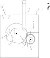
- Figure 4 shows a fourth embodiment of a coupling head according to the invention.
- the coupling head has a coupling component 2 which is rotatably mounted about a main axis of rotation 1 (running perpendicular to the plane of the drawing), which is designed to cooperate with a coupling rod 3 of another, in particular identical, coupling head (not shown in this figure).
- the coupling head also has a coupling rod 3 pivotally connected to the coupling component 2, which is designed to cooperate with a coupling component 2 of the other (not shown) coupling head.
- the coupling head has an actuator 4 with an electric drive motor 5 (not explicitly shown in this figure) and with a three-shaft gear 6 (not explicitly shown in this figure) connected downstream of the electric drive motor 5.
- the three-shaft gear 6 has an output 7 with a first spur gear toothing 31, which meshes with a second spur gear toothing 32 of the coupling component 2.
- the rotation axis 10 of the three-shaft gear 6 (running perpendicular to the plane of the drawing) is aligned parallel to the main rotation axis 1 of the coupling component 2.
- the coupling head has a housing 12 that houses the coupling component 2.
- the housing 12 also houses the actuator 4.
- the actuator 4 is connected to the housing 12 in a rotationally fixed manner.
- the housing 12 has an insertion opening 13 for the (not shown) coupling rod 3 of another coupling head.
- the free end of the coupling rod 3 of the other coupling head is designed and intended to engage in a hook mouth 14 of the coupling component 2.
- the coupling head has a freewheel 11.
- the freewheel 11 is arranged such that it separates the three-shaft gear 6 and the electric drive motor 5 from a rotation of the coupling component 2 with opposite direction of rotation (opposite to the direction of rotation illustrated by arrow 15).
- Figure 5 shows a fifth embodiment of a coupling head according to the invention.
- the coupling head has an actuator 4 with an electric drive motor 5 and a three-shaft gear 6 connected downstream of the electric drive motor 5.
- the three-shaft gear 6 is designed as a strain wave gear in a pot design.
- the drive motor 5 is arranged coaxially with the three-shaft gear. This means that the rotation axis 10 of the three-shaft gear 6 is arranged coaxially with the rotation axis 16 of the drive motor 5.
- the three-shaft gearbox 6 has an output 7 which carries the coupling component 2.
- the rotational axis 10 of the three-shaft gear 6 and the rotational axis 16 of the drive motor 5 are also aligned coaxially with the main rotational axis 1 of the coupling component 2.
- the output component 18 of the drive motor 5 is manufactured in one piece with the drive component 19 of the three-shaft gear 6.
- the three-shaft transmission 6 is designed as a stress wave transmission and has a wave generator 22.
- the wave generator 22 includes an elliptical deformation body 23, which is rotatably mounted within a cup-shaped flexspline 25 by means of a radially flexible wave generator bearing 24.
- the drive component 19 is manufactured in one piece with the deformation body 23.
- the cup-shaped flexspline 25 has an external toothing 26, which meshes with the internal toothing 27 of a Circular splines 28 mesh at least two points.
- the output 7 is rotatably mounted relative to the circular spline 28 by means of a rolling bearing 29. Furthermore, the output 7 is rotatably mounted relative to the circular spline 28 by means of a further rolling bearing 30.
- the rotational bearing of the output 7 realized by means of the rolling bearing 29 is simultaneously also the pivot bearing of the coupling component 2.
Landscapes
- Engineering & Computer Science (AREA)
- Mechanical Engineering (AREA)
- Retarders (AREA)
- Connection Of Motors, Electrical Generators, Mechanical Devices, And The Like (AREA)
Claims (15)
- Tête d'attelage pour un attelage automatique, en particulier pour un attelage Scharfenberg, la tête d'attelage comportant un composant d'accouplement (2) monté de manière à pouvoir tourner autour d'un axe de rotation principal (1), qui est réalisé pour coopérer avec une tige d'accouplement (3) d'une autre tête d'attelage, en particulier identique, la tête d'attelage comportant une tige d'accouplement (3) reliée de manière mobile par pivotement au composant d'accouplement (2), qui est réalisée pour coopérer avec un composant d'accouplement (2) de l'autre tête d'attelage, la tête d'attelage comportant un actionneur (4) avec un moteur d'entraînement (5) électrique, caractérisée en ce que l'actionneur est pourvu d'un engrenage à trois arbres (6) installé en aval en entraînement du moteur d'entraînement (5) électrique, dont la sortie est accouplée au composant d'accouplement (2) pour desserrer le composant d'accouplement (2) d'une position de rotation d'accouplement et/ou pour le faire tourner dans une position de rotation de libération au besoin en cas d'entraînement motorisé, l'axe de rotation (16) du rotor du moteur d'entraînement (5) et/ou l'axe de rotation (10) de l'engrenage à trois arbres (6) étant orientés parallèlement ou coaxialement à l'axe de rotation principal (1) du composant d'accouplement (2).
- Tête d'attelage selon la revendication 1, caractérisée en ce que le composant d'accouplement (2) est réalisé comme un disque à crochet.
- Tête d'attelage selon la revendication 1 ou 2, caractérisée en ce quea. la sortie (7) de l'engrenage à trois arbres (6) est accouplée au composant d'accouplement (2) par un ensemble formant levier, ou queb. la sortie (7) de l'engrenage à trois arbres (6) est accouplée au composant d'accouplement (2) par un ensemble formant levier, l'ensemble formant levier comportant une barre de transmission (9) qui est reliée d'une part de manière mobile par pivotement à la sortie (7) de l'engrenage à trois arbres (6) et d'autre part de manière mobile par pivotement au composant d'accouplement (2), ou quec. la sortie (7) de l'engrenage à trois arbres (6) est accouplée au composant d'accouplement (2) par un ensemble formant levier, la sortie (7) de l'engrenage à trois arbres (6) comportant un levier de sortie (8).
- Tête d'attelage selon la revendication 1 ou 2, caractérisée en ce quea. la sortie (7) de l'engrenage à trois arbres (6) est accouplée au composant d'accouplement (2) par une denture droite, ou queb. la sortie (7) de l'engrenage à trois arbres (6) supporte le composant d'accouplement (2), ou quec. un palier de rotation de la sortie (7) de l'engrenage à trois arbres (6) fait office de palier rotatif pour le composant d'accouplement (2).
- Tête d'attelage selon l'une des revendications 1 à 4, caractérisée en ce quea. la tête d'attelage comporte une roue libre (11), ou queb. la tête d'attelage comporte une roue libre (11), qui découple d'une rotation du composant d'accouplement (2) l'actionneur (4) ou au moins le moteur d'entraînement (5) électrique lors d'une opération de couplage, ou quec. la tête d'attelage comporte une roue libre (11), la sortie (7) de l'engrenage à trois arbres (6) étant accouplée au composant d'accouplement (2) par la roue libre (11) ou la sortie (7) de l'engrenage à trois arbres (6) contenant la roue libre, ou qued. la tête d'attelage comporte une roue libre (11), qui est montée en entraînement entre le moteur d'entraînement (5) électrique et l'engrenage à trois arbres (6).
- Tête d'attelage selon l'une des revendications 1 à 5, caractérisée en ce que l'actionneur (4) est accouplé au composant d'accouplement (2) de telle manière qu'il est repoussé lors d'une opération d'accouplement.
- Tête d'attelage selon l'une des revendications 1 à 6, caractérisée en ce quea. le moteur d'entraînement (5) est disposé coaxialement à l'engrenage à trois arbres (6), ou queb. le moteur d'entraînement (5) est disposé axialement parallèlement à l'engrenage à trois arbres (6), ou quec. le moteur d'entraînement (5) est disposé axialement parallèlement à l'engrenage à trois arbres (6), un mécanisme de traction (17), en particulier un mécanisme à courroie, transmettant un couple de rotation d'un composant de sortie de moteur du moteur d'entraînement (5) à un composant d'entraînement de l'engrenage à trois arbres (6), ou qued. le moteur d'entraînement (5) est disposé axialement parallèlement à l'engrenage à trois arbres (6), un mécanisme de traction (17), en particulier un mécanisme à courroie, transmettant un couple de rotation d'un composant de sortie de moteur du moteur d'entraînement (5) à un composant d'entraînement de l'engrenage à trois arbres (6) et le mécanisme de traction (17) présentant un rapport de démultiplication différent de i = 1.
- Tête d'attelage selon l'une des revendications 1 à 7, caractérisée en ce quea. la tête d'attelage comporte un boîtier (12), qui abrite au moins le composant d'accouplement (2), ou queb. la tête d'attelage comporte un boîtier (12), qui abrite au moins en partie, en particulier totalement, au moins le composant d'accouplement (2) et l'actionneur (4), ou quec. la tête d'attelage comporte un boîtier (12), qui abrite au moins en partie, en particulier totalement, au moins le composant d'accouplement (2) et l'actionneur (4), le moteur d'entraînement (5) étant disposé à l'extérieur du boîtier (12) et l'engrenage à trois arbres (6) étant disposé à l'intérieur du boîtier (12), ou qued. la tête d'attelage comporte un boîtier (12), qui abrite au moins en partie, en particulier totalement, au moins le composant d'accouplement (2), l'actionneur (4) étant disposé à l'extérieur du boîtier (12), ou quee. la tête d'attelage comporte un boîtier (12), au moins un composant de l'actionneur (4) étant relié de manière solidaire en rotation au boîtier (12) et/ou au moins un composant de l'actionneur (4), étant fixé, en particulier directement, de manière solidaire en rotation sur le boîtier (12).
- Tête d'attelage selon l'une des revendications 1 à 8, caractérisée en ce quea. un des arbres de l'engrenage à trois arbres (6) est monté de manière à pouvoir tourner par rapport à un autre arbre de l'engrenage à trois arbres (6) au moyen d'un palier de roulement (29, 30), ou queb. un des arbres de l'engrenage à trois arbres (6) est monté de manière à pouvoir tourner par rapport à un autre arbre de l'engrenage à trois arbres (6) au moyen d'un palier de roulement (29, 30), le palier de roulement (29) faisant office de palier de sortie de l'engrenage à trois arbres (6).
- Tête d'attelage selon l'une des revendications 1 à 9, caractérisée en ce quea. l'engrenage à trois arbres (6) comporte un arbre d'entraînement réalisé en tant qu'un arbre creux, et/ou queb. l'engrenage à trois arbres (6) comporte un accouplement Oldham, et/ou quec. le moteur d'entraînement (5) est accouplé en entraînement à l'engrenage à trois arbres (6) par l'accouplement Oldham.
- Tête d'attelage selon l'une des revendications 1 à 10, caractérisée en ce quea. l'engrenage à trois arbres (6) est un engrenage à ondes de contrainte, et/oub. l'engrenage à trois arbres (6) est un engrenage à ondes de contrainte qui est réalisé comme un engrenage à pot ou comme un engrenage à chapeau ou comme un engrenage annulaire, et/ou quec. l'engrenage à trois arbres (6) est un engrenage à ondes de contrainte, une cannelure circulaire (28) ou une cannelure dynamique de l'engrenage à ondes de contrainte formant la sortie (7) ou faisant partie de la sortie (7) ou une cannelure flexible (25) de l'engrenage à ondes de contrainte formant la sortie (7) ou faisant partie de la sortie (7).
- Tête d'attelage selon l'une des revendications 1 à 11, caractérisée en ce quea. l'engrenage à trois arbres (6) est réalisé comme un engrenage cycloïdal, ou queb. l'engrenage à trois arbres (6) est réalisé comme un engrenage planétaire.
- Attelage automatique, en particulier attelage Scharfenberg, comportant deux têtes d'attelage selon l'une des revendications 1 à 12 en particulier identiques, pouvant être accouplées l'une à l'autre, ou attelage automatique, en particulier attelage Scharfenberg, comportant deux têtes d'attelage selon l'une des revendications 1 à 12 en particulier identiques, pouvant être accouplées l'une à l'autre, un état d'accouplement des têtes d'attelage pouvant être déclenché de manière télécommandée au moyen de l'actionneur (4).
- Véhicule, en particulier véhicule sur rails, avec au moins une tête d'attelage selon l'une des revendications 1 à 12.
- Train avec plusieurs véhicules, en particulier véhicules sur rails, des véhicules directement adjacents étant accouplés les uns aux autres respectivement au moyen d'un attelage automatique selon la revendication 13.
Applications Claiming Priority (1)
| Application Number | Priority Date | Filing Date | Title |
|---|---|---|---|
| LU502810 | 2022-09-16 |
Publications (2)
| Publication Number | Publication Date |
|---|---|
| EP4339060A1 EP4339060A1 (fr) | 2024-03-20 |
| EP4339060B1 true EP4339060B1 (fr) | 2025-06-04 |
Family
ID=84332062
Family Applications (1)
| Application Number | Title | Priority Date | Filing Date |
|---|---|---|---|
| EP23197197.9A Active EP4339060B1 (fr) | 2022-09-16 | 2023-09-13 | Tête d'attelage à accouplement automatique de type scharfenberg |
Country Status (1)
| Country | Link |
|---|---|
| EP (1) | EP4339060B1 (fr) |
Family Cites Families (3)
| Publication number | Priority date | Publication date | Assignee | Title |
|---|---|---|---|---|
| DE149727C (fr) | ||||
| DE102021133227A1 (de) * | 2020-12-15 | 2022-06-15 | Voith Patent Gmbh | Automatische Zugkupplung |
| DE102021132991A1 (de) | 2020-12-15 | 2022-06-15 | Voith Patent Gmbh | Automatische Zugkupplung und Verfahren zum Entkuppeln einer automatischen Zugkupplung |
-
2023
- 2023-09-13 EP EP23197197.9A patent/EP4339060B1/fr active Active
Also Published As
| Publication number | Publication date |
|---|---|
| EP4339060A1 (fr) | 2024-03-20 |
Similar Documents
| Publication | Publication Date | Title |
|---|---|---|
| DE10207540B4 (de) | Motorvorrichtung zum Betätigen einer Fahrzeugtürbetätigungsvorrichtung | |
| EP3323718B1 (fr) | Boîte de transmission pour rotor d'hélicoptère | |
| EP3487721B1 (fr) | Ensemble de transmission destiné à un véhicule hybride, système d'entraînement et véhicule hybride | |
| DE102012011686A1 (de) | Übersetzungs- und Ausgleichsgetriebe sowie Motor- und Getriebeeinheit | |
| DE102019201639B4 (de) | Getriebeeinrichtung für ein Kraftfahrzeug | |
| DE3424309A1 (de) | Lenkkraft-uebertragungs-vorrichtung | |
| DE3444314A1 (de) | Hilfsaggregatantrieb bei einer turbine | |
| DE60111975T2 (de) | Verteilergetriebe für Fahrzeug mit Vierradantrieb | |
| DE102019202865A1 (de) | Gelenkwellenstruktur eines Roboters sowie Roboter | |
| WO2019038208A1 (fr) | Dispositif de transmission pour véhicule automobile | |
| AT413747B (de) | Winkelgetriebe mit integrierter drehspielkupplung | |
| EP4339060B1 (fr) | Tête d'attelage à accouplement automatique de type scharfenberg | |
| DE3800767A1 (de) | Vorrichtung fuer die bewegung eines torblattes wahlweise mittels eines sicherheitsueberwachten motorantriebes oder eines antriebes von hand | |
| EP3892889A1 (fr) | Transmission à démultiplication harmonique | |
| DE102019201638B4 (de) | Getriebeeinrichtung für ein Kraftfahrzeug | |
| DE2817106A1 (de) | Vorrichtung fuer den automatischen ausgleich von ausfluchtungsfehlern | |
| DE102022123772A1 (de) | Kupplungskopf für eine Scharfenbergkupplung | |
| WO2015139913A1 (fr) | Ensemble d'essieux rigides comprenant un corps d'essieu s'étendant dans le sens transversal d'un véhicule | |
| DE102018005372A1 (de) | Antriebseinrichtung für ein Kraftfahrzeug, insbesondere für ein Hybrid- oder Elektrofahrzeug | |
| WO2013045076A1 (fr) | Transmission d'une éolienne dotée d'un entraînement auxiliaire, éolienne et procédé destiné à amener en rotation un arbre de rotor d'une éolienne | |
| DE102018216251B3 (de) | Antriebsstranganordnung mit einer entkopplungseinheit zum entkoppeln einer antriebswelle von einer abtriebswelle | |
| DE69826926T3 (de) | Reduktionsgetriebe für eine Betonmischmaschine | |
| DE102017216159A1 (de) | Getriebeeinrichtung für ein Kraftfahrzeug sowie entsprechendes Kraftfahrzeug | |
| EP1679455B1 (fr) | Agencement d'un levier de commande pour une transmission automatique | |
| WO2020160864A1 (fr) | Dispositif de transmission pour véhicule automobile |
Legal Events
| Date | Code | Title | Description |
|---|---|---|---|
| PUAI | Public reference made under article 153(3) epc to a published international application that has entered the european phase |
Free format text: ORIGINAL CODE: 0009012 |
|
| STAA | Information on the status of an ep patent application or granted ep patent |
Free format text: STATUS: THE APPLICATION HAS BEEN PUBLISHED |
|
| AK | Designated contracting states |
Kind code of ref document: A1 Designated state(s): AL AT BE BG CH CY CZ DE DK EE ES FI FR GB GR HR HU IE IS IT LI LT LU LV MC ME MK MT NL NO PL PT RO RS SE SI SK SM TR |
|
| STAA | Information on the status of an ep patent application or granted ep patent |
Free format text: STATUS: REQUEST FOR EXAMINATION WAS MADE |
|
| 17P | Request for examination filed |
Effective date: 20240913 |
|
| RBV | Designated contracting states (corrected) |
Designated state(s): AL AT BE BG CH CY CZ DE DK EE ES FI FR GB GR HR HU IE IS IT LI LT LU LV MC ME MK MT NL NO PL PT RO RS SE SI SK SM TR |
|
| GRAP | Despatch of communication of intention to grant a patent |
Free format text: ORIGINAL CODE: EPIDOSNIGR1 |
|
| STAA | Information on the status of an ep patent application or granted ep patent |
Free format text: STATUS: GRANT OF PATENT IS INTENDED |
|
| INTG | Intention to grant announced |
Effective date: 20250102 |
|
| GRAS | Grant fee paid |
Free format text: ORIGINAL CODE: EPIDOSNIGR3 |
|
| GRAA | (expected) grant |
Free format text: ORIGINAL CODE: 0009210 |
|
| STAA | Information on the status of an ep patent application or granted ep patent |
Free format text: STATUS: THE PATENT HAS BEEN GRANTED |
|
| AK | Designated contracting states |
Kind code of ref document: B1 Designated state(s): AL AT BE BG CH CY CZ DE DK EE ES FI FR GB GR HR HU IE IS IT LI LT LU LV MC ME MK MT NL NO PL PT RO RS SE SI SK SM TR |
|
| REG | Reference to a national code |
Ref country code: GB Ref legal event code: FG4D Free format text: NOT ENGLISH |
|
| REG | Reference to a national code |
Ref country code: CH Ref legal event code: EP |
|
| REG | Reference to a national code |
Ref country code: DE Ref legal event code: R096 Ref document number: 502023001089 Country of ref document: DE |
|
| REG | Reference to a national code |
Ref country code: IE Ref legal event code: FG4D Free format text: LANGUAGE OF EP DOCUMENT: GERMAN |
|
| REG | Reference to a national code |
Ref country code: NL Ref legal event code: MP Effective date: 20250604 |
|
| PG25 | Lapsed in a contracting state [announced via postgrant information from national office to epo] |
Ref country code: ES Free format text: LAPSE BECAUSE OF FAILURE TO SUBMIT A TRANSLATION OF THE DESCRIPTION OR TO PAY THE FEE WITHIN THE PRESCRIBED TIME-LIMIT Effective date: 20250604 Ref country code: FI Free format text: LAPSE BECAUSE OF FAILURE TO SUBMIT A TRANSLATION OF THE DESCRIPTION OR TO PAY THE FEE WITHIN THE PRESCRIBED TIME-LIMIT Effective date: 20250604 |
|
| PGFP | Annual fee paid to national office [announced via postgrant information from national office to epo] |
Ref country code: DE Payment date: 20250918 Year of fee payment: 3 |
|
| REG | Reference to a national code |
Ref country code: LT Ref legal event code: MG9D |
|
| PG25 | Lapsed in a contracting state [announced via postgrant information from national office to epo] |
Ref country code: NO Free format text: LAPSE BECAUSE OF FAILURE TO SUBMIT A TRANSLATION OF THE DESCRIPTION OR TO PAY THE FEE WITHIN THE PRESCRIBED TIME-LIMIT Effective date: 20250904 |
|
| PG25 | Lapsed in a contracting state [announced via postgrant information from national office to epo] |
Ref country code: PL Free format text: LAPSE BECAUSE OF FAILURE TO SUBMIT A TRANSLATION OF THE DESCRIPTION OR TO PAY THE FEE WITHIN THE PRESCRIBED TIME-LIMIT Effective date: 20250604 |
|
| PG25 | Lapsed in a contracting state [announced via postgrant information from national office to epo] |
Ref country code: BG Free format text: LAPSE BECAUSE OF FAILURE TO SUBMIT A TRANSLATION OF THE DESCRIPTION OR TO PAY THE FEE WITHIN THE PRESCRIBED TIME-LIMIT Effective date: 20250604 |
|
| PG25 | Lapsed in a contracting state [announced via postgrant information from national office to epo] |
Ref country code: HR Free format text: LAPSE BECAUSE OF FAILURE TO SUBMIT A TRANSLATION OF THE DESCRIPTION OR TO PAY THE FEE WITHIN THE PRESCRIBED TIME-LIMIT Effective date: 20250604 |
|
| PGFP | Annual fee paid to national office [announced via postgrant information from national office to epo] |
Ref country code: AT Payment date: 20251020 Year of fee payment: 3 |
|
| PG25 | Lapsed in a contracting state [announced via postgrant information from national office to epo] |
Ref country code: RS Free format text: LAPSE BECAUSE OF FAILURE TO SUBMIT A TRANSLATION OF THE DESCRIPTION OR TO PAY THE FEE WITHIN THE PRESCRIBED TIME-LIMIT Effective date: 20250904 |
|
| PG25 | Lapsed in a contracting state [announced via postgrant information from national office to epo] |
Ref country code: LV Free format text: LAPSE BECAUSE OF FAILURE TO SUBMIT A TRANSLATION OF THE DESCRIPTION OR TO PAY THE FEE WITHIN THE PRESCRIBED TIME-LIMIT Effective date: 20250604 |
|
| PG25 | Lapsed in a contracting state [announced via postgrant information from national office to epo] |
Ref country code: NL Free format text: LAPSE BECAUSE OF FAILURE TO SUBMIT A TRANSLATION OF THE DESCRIPTION OR TO PAY THE FEE WITHIN THE PRESCRIBED TIME-LIMIT Effective date: 20250604 |
|
| PG25 | Lapsed in a contracting state [announced via postgrant information from national office to epo] |
Ref country code: PT Free format text: LAPSE BECAUSE OF FAILURE TO SUBMIT A TRANSLATION OF THE DESCRIPTION OR TO PAY THE FEE WITHIN THE PRESCRIBED TIME-LIMIT Effective date: 20251006 |
|
| PG25 | Lapsed in a contracting state [announced via postgrant information from national office to epo] |
Ref country code: IS Free format text: LAPSE BECAUSE OF FAILURE TO SUBMIT A TRANSLATION OF THE DESCRIPTION OR TO PAY THE FEE WITHIN THE PRESCRIBED TIME-LIMIT Effective date: 20251004 |
|
| PG25 | Lapsed in a contracting state [announced via postgrant information from national office to epo] |
Ref country code: SM Free format text: LAPSE BECAUSE OF FAILURE TO SUBMIT A TRANSLATION OF THE DESCRIPTION OR TO PAY THE FEE WITHIN THE PRESCRIBED TIME-LIMIT Effective date: 20250604 |
|
| PG25 | Lapsed in a contracting state [announced via postgrant information from national office to epo] |
Ref country code: CZ Free format text: LAPSE BECAUSE OF FAILURE TO SUBMIT A TRANSLATION OF THE DESCRIPTION OR TO PAY THE FEE WITHIN THE PRESCRIBED TIME-LIMIT Effective date: 20250604 |
|
| PG25 | Lapsed in a contracting state [announced via postgrant information from national office to epo] |
Ref country code: EE Free format text: LAPSE BECAUSE OF FAILURE TO SUBMIT A TRANSLATION OF THE DESCRIPTION OR TO PAY THE FEE WITHIN THE PRESCRIBED TIME-LIMIT Effective date: 20250604 |
|
| PG25 | Lapsed in a contracting state [announced via postgrant information from national office to epo] |
Ref country code: SK Free format text: LAPSE BECAUSE OF FAILURE TO SUBMIT A TRANSLATION OF THE DESCRIPTION OR TO PAY THE FEE WITHIN THE PRESCRIBED TIME-LIMIT Effective date: 20250604 |
|
| PG25 | Lapsed in a contracting state [announced via postgrant information from national office to epo] |
Ref country code: IT Free format text: LAPSE BECAUSE OF FAILURE TO SUBMIT A TRANSLATION OF THE DESCRIPTION OR TO PAY THE FEE WITHIN THE PRESCRIBED TIME-LIMIT Effective date: 20250604 |
|
| REG | Reference to a national code |
Ref country code: DE Ref legal event code: R097 Ref document number: 502023001089 Country of ref document: DE |
|
| PG25 | Lapsed in a contracting state [announced via postgrant information from national office to epo] |
Ref country code: RO Free format text: LAPSE BECAUSE OF FAILURE TO SUBMIT A TRANSLATION OF THE DESCRIPTION OR TO PAY THE FEE WITHIN THE PRESCRIBED TIME-LIMIT Effective date: 20250604 |
|
| PLBE | No opposition filed within time limit |
Free format text: ORIGINAL CODE: 0009261 |
|
| STAA | Information on the status of an ep patent application or granted ep patent |
Free format text: STATUS: NO OPPOSITION FILED WITHIN TIME LIMIT |
|
| PG25 | Lapsed in a contracting state [announced via postgrant information from national office to epo] |
Ref country code: DK Free format text: LAPSE BECAUSE OF FAILURE TO SUBMIT A TRANSLATION OF THE DESCRIPTION OR TO PAY THE FEE WITHIN THE PRESCRIBED TIME-LIMIT Effective date: 20250604 |
|
| REG | Reference to a national code |
Ref country code: CH Ref legal event code: L10 Free format text: ST27 STATUS EVENT CODE: U-0-0-L10-L00 (AS PROVIDED BY THE NATIONAL OFFICE) Effective date: 20260416 |