EP4337830B1 - Bagger mit greifer - Google Patents
Bagger mit greifer Download PDFInfo
- Publication number
- EP4337830B1 EP4337830B1 EP21736361.3A EP21736361A EP4337830B1 EP 4337830 B1 EP4337830 B1 EP 4337830B1 EP 21736361 A EP21736361 A EP 21736361A EP 4337830 B1 EP4337830 B1 EP 4337830B1
- Authority
- EP
- European Patent Office
- Prior art keywords
- windup
- grab bucket
- angles
- bucket excavator
- excavator according
- Prior art date
- Legal status (The legal status is an assumption and is not a legal conclusion. Google has not performed a legal analysis and makes no representation as to the accuracy of the status listed.)
- Active
Links
Images
Classifications
-
- E—FIXED CONSTRUCTIONS
- E02—HYDRAULIC ENGINEERING; FOUNDATIONS; SOIL SHIFTING
- E02D—FOUNDATIONS; EXCAVATIONS; EMBANKMENTS; UNDERGROUND OR UNDERWATER STRUCTURES
- E02D17/00—Excavations; Bordering of excavations; Making embankments
- E02D17/13—Foundation slots or slits; Implements for making these slots or slits
-
- E—FIXED CONSTRUCTIONS
- E02—HYDRAULIC ENGINEERING; FOUNDATIONS; SOIL SHIFTING
- E02F—DREDGING; SOIL-SHIFTING
- E02F3/00—Dredgers; Soil-shifting machines
- E02F3/04—Dredgers; Soil-shifting machines mechanically-driven
- E02F3/18—Dredgers; Soil-shifting machines mechanically-driven with digging wheels turning round an axis, e.g. bucket-type wheels
- E02F3/22—Component parts
-
- E—FIXED CONSTRUCTIONS
- E02—HYDRAULIC ENGINEERING; FOUNDATIONS; SOIL SHIFTING
- E02F—DREDGING; SOIL-SHIFTING
- E02F3/00—Dredgers; Soil-shifting machines
- E02F3/04—Dredgers; Soil-shifting machines mechanically-driven
- E02F3/28—Dredgers; Soil-shifting machines mechanically-driven with digging tools mounted on a dipper- or bucket-arm, i.e. there is either one arm or a pair of arms, e.g. dippers, buckets
- E02F3/36—Component parts
- E02F3/40—Dippers; Buckets ; Grab devices, e.g. manufacturing processes for buckets, form, geometry or material of buckets
- E02F3/413—Dippers; Buckets ; Grab devices, e.g. manufacturing processes for buckets, form, geometry or material of buckets with grabbing device
-
- E—FIXED CONSTRUCTIONS
- E02—HYDRAULIC ENGINEERING; FOUNDATIONS; SOIL SHIFTING
- E02F—DREDGING; SOIL-SHIFTING
- E02F9/00—Component parts of dredgers or soil-shifting machines, not restricted to one of the kinds covered by groups E02F3/00 - E02F7/00
- E02F9/20—Drives; Control devices
- E02F9/22—Hydraulic or pneumatic drives
- E02F9/2264—Arrangements or adaptations of elements for hydraulic drives
- E02F9/2275—Hoses and supports therefor and protection therefor
-
- F—MECHANICAL ENGINEERING; LIGHTING; HEATING; WEAPONS; BLASTING
- F16—ENGINEERING ELEMENTS AND UNITS; GENERAL MEASURES FOR PRODUCING AND MAINTAINING EFFECTIVE FUNCTIONING OF MACHINES OR INSTALLATIONS; THERMAL INSULATION IN GENERAL
- F16L—PIPES; JOINTS OR FITTINGS FOR PIPES; SUPPORTS FOR PIPES, CABLES OR PROTECTIVE TUBING; MEANS FOR THERMAL INSULATION IN GENERAL
- F16L11/00—Hoses, i.e. flexible pipes
- F16L11/04—Hoses, i.e. flexible pipes made of rubber or flexible plastics
- F16L11/08—Hoses, i.e. flexible pipes made of rubber or flexible plastics with reinforcements embedded in the wall
- F16L11/081—Hoses, i.e. flexible pipes made of rubber or flexible plastics with reinforcements embedded in the wall comprising one or more layers of a helically wound cord or wire
- F16L11/083—Hoses, i.e. flexible pipes made of rubber or flexible plastics with reinforcements embedded in the wall comprising one or more layers of a helically wound cord or wire three or more layers
Definitions
- the present innovation relates to a grab bucket excavator.
- the present innovation relates to a grab bucket excavator of the type comprising a self-propelled vehicle, for example a tracked self-propelled vehicle; a grab bucket comprising, in turn, two shovels movable with respect to each other between an open position and a closed position; a lifting device fitted on the self-propelled vehicle for lowering and lifting the grab bucket; and a hydraulic drive device for moving the shovels between the open position and the closed position.
- the lifting device comprises a pair of pulling ropes, which are hooked on one side onto the bucket and on the other side onto respective winding rollers fitted on the self-propelled vehicle, and are wound around at least two return pulleys fitted at a free upper end of an upright extending upwards from the self-propelled vehicle.
- the hydraulic drive device normally comprises at least one actuator cylinder connected to the shovels and at least one flexible pipe, which supplies a fluid under pressure to the actuator cylinder, and is hooked on one side onto the actuator cylinder and on the other side onto a winding roller fitted on the self-propelled vehicle.
- the flexible pipe Since the known grab bucket excavators of the type described above are used for making perforations having a relatively high depth, the flexible pipe has, inside the perforation, a relatively long length subjected to a relatively high axial traction force generated by the grab bucket and by the winding roller of the flexible pipe.
- the known grab bucket excavators of the type described above have some drawbacks mainly deriving from the fact that the flexible pipes currently used have a relatively high radial resistance to the fluid under pressure but a relatively reduced axial resistance to the traction.
- the object of the present innovation is to provide a grab bucket excavator which is exempt from the drawbacks described above and which is simple and cost-effective to manufacture.
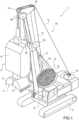
- reference numeral 1 indicates, as a whole, a grab bucket excavator comprising a self-propelled vehicle 2, in this case a tracked vehicle, provided with an operator cab 3 and with an upright 4 extending upwards from the self-propelled vehicle 2.
- the excavator 1 further has a perforation device 5 comprising a supporting frame 6 and a bucket 7 provided with two shovels 8 rotatably coupled to the frame 6 for rotating, with respect to the frame 6 and under the thrust of a hydraulic drive device 9, between an open position ( Figure 1 ) and a closed position (not illustrated).
- a perforation device 5 comprising a supporting frame 6 and a bucket 7 provided with two shovels 8 rotatably coupled to the frame 6 for rotating, with respect to the frame 6 and under the thrust of a hydraulic drive device 9, between an open position ( Figure 1 ) and a closed position (not illustrated).
- the excavator 1 is further provided with a lifting device 10 for lifting and lowering the device 5.
- the device 10 comprises, in this case, two pulling ropes 11, which are hooked on one side onto the frame 6 and on the other side onto respective winding rollers 12 fitted on the vehicle 2, and are wound around at least two return pulleys 13 fitted at a free upper end of the upright 4.
- the device 9 comprises at least one known and not shown actuator cylinder, which is fixed to the frame 6, has an output rod connected to the shovels 8, and is operated by a fluid under pressure supplied along a pair of flexible pipes 14, which are connected on one side to the actuator cylinder (not illustrated) and on the other side to respective winding rollers 15 fitted on the vehicle 2, and are wound around respective return pulleys 16 fitted along and at the free upper end of the upright 4.
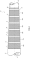
- each pipe 14 has a longitudinal axis 17, and comprises, in this case:
- the layers 20 are helically wound around the axis 17 in an alternated manner in two windup directions opposite to each other.
- the two layers 20 adjacent the outer tube 19 are wound around the axis 17 with respective windup angles ⁇ , which are comprised between 36° and 54°, in particular are equal to 45°, and are equal to or differ from each other.
- the remaining four layers 20 are wound around the axis 17 with respective windup angles ⁇ , which are comprised between 48° and 62°, in particular are equal to 54°44', are equal to or differ from each other, and differ from the angles ⁇ .
- the pipe 14 further comprises a plurality of intermediate layers 21, each of which is interposed between two adjacent layers 20 for ensuring the adhesion between the layers 20, and is made of polymeric material.
- the pipe 14 further has a consolidation layer 22, which is made of textile material, and is fitted on the tube 18 for ensuring a relatively high resistance to the tube 18 both during the manufacturing of the pipe 14, and at the coupling zone of the pipe 14 to the actuator cylinder (not illustrated).
- a consolidation layer 22 which is made of textile material, and is fitted on the tube 18 for ensuring a relatively high resistance to the tube 18 both during the manufacturing of the pipe 14, and at the coupling zone of the pipe 14 to the actuator cylinder (not illustrated).
- the pipe 14 further comprises a further intermediate layer 23, which is totally analogous to the layers 21, and is interposed between the layer 22 and the adjacent layer 20b so as to ensure the adhesion between the layer 22 and the layer 20b.
- the inner tube 18, the outer tube 19, the reinforcement layers 20, the intermediate layers 21, 23, and the consolidation layer 22 have a length equal to a length of the pipe 14.
- the number of layers 20b is different from four, for example equal to six or eight.
- the excavator 1 has some advantages mainly deriving from the fact that the layers 20b of each pipe 14 cooperate with the relative tube 18 for ensuring to the pipe 14 a relatively high radial resistance to the fluid under pressure and that the layers 20a ensure to the pipe 14 a relatively high flexibility, elasticity and, thus, an axial resistance to the traction.
- the axial resistance to the traction of the pipes 14 is further improved by the difference of at least 2° existing between the angles ⁇ and the angles ⁇ .
Landscapes
- Engineering & Computer Science (AREA)
- General Engineering & Computer Science (AREA)
- Mining & Mineral Resources (AREA)
- Civil Engineering (AREA)
- Structural Engineering (AREA)
- Mechanical Engineering (AREA)
- Life Sciences & Earth Sciences (AREA)
- General Life Sciences & Earth Sciences (AREA)
- Paleontology (AREA)
- Earth Drilling (AREA)
- Load-Engaging Elements For Cranes (AREA)
- Component Parts Of Construction Machinery (AREA)
Claims (12)
- Greifbagger umfassend ein selbstfahrendes Fahrzeug (2); einen Greifkorb (7), der seinerseits zwei Schaufeln (8) umfasst, die zwischen einer offenen und einer geschlossenen Stellung zueinander beweglich sind; einer Hebevorrichtung (10), die an dem selbstfahrenden Fahrzeug (2) zum Absenken und Anheben des Greifkorbes (7) eingebaut ist; und eine hydraulische Antriebsvorrichtung (9) zum Bewegen der Schaufeln (8) zwischen der offenen und der geschlossenen Stellung; wobei die hydraulische Antriebsvorrichtung (9) mindestens einen mit den Schaufeln (8) verbundenen Betätigungszylinder, mindestens ein flexibles Rohr (14) zum Zuführen eines Fluids unter Druck zu dem Betätigungszylinder und für jedes flexible Rohr (14) eine entsprechende Wickelrolle (15) umfasst, die an dem selbstfahrenden Fahrzeug (2) eingebaut ist; und dadurch gekennzeichnet, dass das flexible Rohr (14) ein Innenrohr (18), ein Außenrohr (19); mindestens sechs Verstärkungsschichten (20), die zwischen dem Innenrohr (18) und dem Außenrohr (19) angeordnet sind und schraubenförmig um eine Längsachse (17) des flexiblen Rohrs (14) in abwechselnder Weise in zwei einander entgegengesetzten Aufwicklungsrichtungen gewickelt sind; und eine Mehrzahl von Zwischenschichten (21) umfasst, die jeweils zwischen zwei jeweiligen angrenzenden Verstärkungsschichten (20) angeordnet sind, um die Haftung zwischen den Verstärkungsschichten (20) sicherzustellen; wobei die beiden an das Außenrohr (19) angrenzenden Verstärkungsschichten (20a) mit jeweiligen ersten Aufwicklungswinkeln (α) um die Längsachse (17) gewickelt sind und die übrigen Verstärkungsschichten (20b) mit jeweiligen zweiten Aufwicklungswinkeln (β), die sich von den ersten Aufwicklungswinkeln (α) unterscheiden, um die Längsachse (17) gewickelt sind.
- Greifbagger nach Anspruch 1, wobei jeder erste Aufwicklungswinkel (α) zwischen 36° und 54° liegt, insbesondere gleich 45° ist.
- Greifbagger nach Anspruch 1 oder 2, wobei jeder zweite Aufwicklungswinkel (β) zwischen 48° und 62° liegt, insbesondere gleich 54°44'ist.
- Greifbagger nach einem der vorhergehenden Ansprüche, wobei die ersten Aufwicklungswinkel (α) gleich miteinander sind oder verschieden voneinander sind.
- Greifbagger nach einem der vorhergehenden Ansprüche, wobei die zweiten Aufwicklungswinkel (β) gleich miteinander sind oder verschieden voneinander sind.
- Greifbagger nach einem der vorhergehenden Ansprüche, wobei die ersten Aufwicklungswinkel (α) gleich miteinander sind, die zweiten Aufwicklungswinkel (β) gleich miteinander sind und der Unterschied zwischen den ersten Aufwicklungswinkeln (α) und den zweiten Aufwicklungswinkeln (β) zwischen 2° und 15° liegt.
- Greifbagger nach einem der vorhergehenden Ansprüche 1 bis 5, wobei sich die ersten Aufwicklungswinkel (α) voneinander unterscheiden, sich die zweiten Aufwicklungswinkel (β) voneinander unterscheiden und der Unterschied zwischen dem größten der ersten Aufwicklungswinkel (α) und dem kleinsten der zweiten Aufwicklungswinkel (β) zwischen 2° und 15° liegt.
- Greifbagger nach einem der vorhergehenden Ansprüche, wobei das Innenrohr (18) und das Außenrohr (19) aus einem Polymerwerkstoff bestehen.
- Greifbagger nach einem der vorhergehenden Ansprüche, wobei die Zwischenschichten (21) aus Polymerwerkstoff bestehen.
- Greifbagger nach einem der vorhergehenden Ansprüche, wobei jede Verstärkungsschicht (20) eine Mehrzahl von Drähten aus Metallwerkstoff umfasst.
- Greifbagger nach einem der vorhergehenden Ansprüche, wobei das flexible Rohr (14) ferner eine auf dem Innenrohr (18) eingebaute Verfestigungsschicht (22) umfasst, die aus Textilwerkstoff besteht.
- Greifbagger nach Anspruch 11, wobei das flexible Rohr (14) ferner eine weitere Zwischenschicht (23) umfasst, die zwischen der Verfestigungsschicht (22) und der angrenzenden Verstärkungsschicht (20b) angeordnet ist.
Priority Applications (1)
| Application Number | Priority Date | Filing Date | Title |
|---|---|---|---|
| HUE21736361A HUE069580T2 (hu) | 2021-05-13 | 2021-05-13 | Markolókanalas kotrógép |
Applications Claiming Priority (1)
| Application Number | Priority Date | Filing Date | Title |
|---|---|---|---|
| PCT/IB2021/054088 WO2022238735A1 (en) | 2021-05-13 | 2021-05-13 | Grab bucket excavator |
Publications (3)
| Publication Number | Publication Date |
|---|---|
| EP4337830A1 EP4337830A1 (de) | 2024-03-20 |
| EP4337830B1 true EP4337830B1 (de) | 2024-10-30 |
| EP4337830C0 EP4337830C0 (de) | 2024-10-30 |
Family
ID=76708256
Family Applications (1)
| Application Number | Title | Priority Date | Filing Date |
|---|---|---|---|
| EP21736361.3A Active EP4337830B1 (de) | 2021-05-13 | 2021-05-13 | Bagger mit greifer |
Country Status (9)
| Country | Link |
|---|---|
| US (1) | US20240254721A1 (de) |
| EP (1) | EP4337830B1 (de) |
| CN (1) | CN117957349A (de) |
| BR (1) | BR112023023810A2 (de) |
| ES (1) | ES3002257T3 (de) |
| HU (1) | HUE069580T2 (de) |
| MX (1) | MX2023013278A (de) |
| PL (1) | PL4337830T3 (de) |
| WO (1) | WO2022238735A1 (de) |
Family Cites Families (12)
| Publication number | Priority date | Publication date | Assignee | Title |
|---|---|---|---|---|
| NL6706959A (de) * | 1966-06-08 | 1967-12-11 | ||
| DE2501780C3 (de) * | 1975-01-17 | 1979-07-12 | Liebherr-Hydraulikbagger Gmbh, 7951 Kirchdorf | Hydraulikbagger |
| US5176179A (en) * | 1983-12-22 | 1993-01-05 | Institut Francais Du Petrole | Flexible duct having no appreciable variation in length under the effect of an internal pressure |
| US4850395A (en) * | 1987-12-11 | 1989-07-25 | Simplex Wire & Cable | High pressure flexible pipe |
| GB0406084D0 (en) * | 2004-03-18 | 2004-04-21 | Bellamy Norman W | Lining pipelines using thermoplastic sheet and strip |
| US7987875B2 (en) * | 2004-07-08 | 2011-08-02 | Nkt Flexibles I/S | Flexible pipe, its manufacture and use |
| ES2328521T3 (es) * | 2007-01-26 | 2009-11-13 | Bauer Maschinen Gmbh | Dispositivo de excavacion del suelo. |
| GB0800155D0 (en) * | 2008-01-07 | 2008-02-13 | Wellstream Int Ltd | Flexible pipe having pressure armour layer |
| CA2742672C (en) * | 2008-11-21 | 2017-06-27 | Parker-Hannifin Corporation | Low temperature, high pressure rubber hose |
| FR2967426A1 (fr) * | 2010-11-17 | 2012-05-18 | Colas Sa | Fleche a benne d'excavation grande profondeur pour pelle mecanique a commande hydraulique et pelle avec une telle fleche |
| FR3020859B1 (fr) * | 2014-05-06 | 2016-06-24 | Technip France | Conduite flexible non liee de transport d'un materiau abrasif, procede et utilisation associes |
| CN207079189U (zh) * | 2017-03-28 | 2018-03-09 | 陕西迈纬尔胶管有限公司 | 一种液压胶管 |
-
2021
- 2021-05-13 HU HUE21736361A patent/HUE069580T2/hu unknown
- 2021-05-13 CN CN202180099674.XA patent/CN117957349A/zh active Pending
- 2021-05-13 PL PL21736361.3T patent/PL4337830T3/pl unknown
- 2021-05-13 WO PCT/IB2021/054088 patent/WO2022238735A1/en not_active Ceased
- 2021-05-13 US US18/560,476 patent/US20240254721A1/en active Pending
- 2021-05-13 MX MX2023013278A patent/MX2023013278A/es unknown
- 2021-05-13 BR BR112023023810A patent/BR112023023810A2/pt unknown
- 2021-05-13 EP EP21736361.3A patent/EP4337830B1/de active Active
- 2021-05-13 ES ES21736361T patent/ES3002257T3/es active Active
Also Published As
| Publication number | Publication date |
|---|---|
| ES3002257T3 (en) | 2025-03-06 |
| EP4337830A1 (de) | 2024-03-20 |
| HUE069580T2 (hu) | 2025-03-28 |
| PL4337830T3 (pl) | 2025-03-10 |
| MX2023013278A (es) | 2023-12-15 |
| BR112023023810A2 (pt) | 2024-01-30 |
| US20240254721A1 (en) | 2024-08-01 |
| WO2022238735A1 (en) | 2022-11-17 |
| EP4337830C0 (de) | 2024-10-30 |
| CN117957349A (zh) | 2024-04-30 |
Similar Documents
| Publication | Publication Date | Title |
|---|---|---|
| US8241453B2 (en) | Method and apparatus for manufacturing fibre-reinforced hoses | |
| CA2947785C (fr) | Conduite flexible non liee de transport d'un materiau abrasif, procede et utilisation associes | |
| AU2014201379B2 (en) | Reel with stepped configuration | |
| US6283206B1 (en) | Gas lift umbilical cable and termination assemblies therefor | |
| CN102272504A (zh) | 增强防护件 | |
| AU2013245549B2 (en) | Conduit support system | |
| TW201420929A (zh) | 到離岸設備之管線的內襯 | |
| US3740958A (en) | Method of fabricating and installing a submergible pipeline | |
| JP6049264B2 (ja) | 高圧ホース | |
| US20060201566A1 (en) | Hose with integral coupling and method for producing the same | |
| AU2017229506B2 (en) | Improved dragline bucket rigging system | |
| US20240254721A1 (en) | Grab Bucket Excavator | |
| WO2019038665A1 (en) | TRAINING BODY CABLE AND SHOVEL | |
| CN109562424B (zh) | 半月形升降装置 | |
| JP2002173947A (ja) | 掘削機 | |
| JP2012255289A (ja) | 掘削孔壁防護管のシール装置 | |
| KR100497031B1 (ko) | 지면에서깊은도랑을굴착하는장치와상기장치에의해도랑을굴착하는방법 | |
| US20200095727A1 (en) | Armored Rigging System | |
| JP5511022B2 (ja) | H&vシールド掘進機 | |
| JP2002005344A (ja) | ゴムスリーブホース | |
| KR100525159B1 (ko) | 하수의 흐름이 원활한 비 굴착 방식의 하수관로 보수공법 | |
| US20250116084A1 (en) | Hoist rope protection | |
| JP7862846B2 (ja) | 建機用バケット | |
| US20170016558A1 (en) | Hose for conveying fluids | |
| JP6877825B2 (ja) | 接合装置およびフォークリフト |
Legal Events
| Date | Code | Title | Description |
|---|---|---|---|
| STAA | Information on the status of an ep patent application or granted ep patent |
Free format text: STATUS: UNKNOWN |
|
| STAA | Information on the status of an ep patent application or granted ep patent |
Free format text: STATUS: THE INTERNATIONAL PUBLICATION HAS BEEN MADE |
|
| PUAI | Public reference made under article 153(3) epc to a published international application that has entered the european phase |
Free format text: ORIGINAL CODE: 0009012 |
|
| STAA | Information on the status of an ep patent application or granted ep patent |
Free format text: STATUS: REQUEST FOR EXAMINATION WAS MADE |
|
| 17P | Request for examination filed |
Effective date: 20231124 |
|
| AK | Designated contracting states |
Kind code of ref document: A1 Designated state(s): AL AT BE BG CH CY CZ DE DK EE ES FI FR GB GR HR HU IE IS IT LI LT LU LV MC MK MT NL NO PL PT RO RS SE SI SK SM TR |
|
| GRAP | Despatch of communication of intention to grant a patent |
Free format text: ORIGINAL CODE: EPIDOSNIGR1 |
|
| STAA | Information on the status of an ep patent application or granted ep patent |
Free format text: STATUS: GRANT OF PATENT IS INTENDED |
|
| DAX | Request for extension of the european patent (deleted) | ||
| INTG | Intention to grant announced |
Effective date: 20240528 |
|
| RAV | Requested validation state of the european patent: fee paid |
Extension state: MA Effective date: 20231124 |
|
| GRAS | Grant fee paid |
Free format text: ORIGINAL CODE: EPIDOSNIGR3 |
|
| GRAA | (expected) grant |
Free format text: ORIGINAL CODE: 0009210 |
|
| STAA | Information on the status of an ep patent application or granted ep patent |
Free format text: STATUS: THE PATENT HAS BEEN GRANTED |
|
| AK | Designated contracting states |
Kind code of ref document: B1 Designated state(s): AL AT BE BG CH CY CZ DE DK EE ES FI FR GB GR HR HU IE IS IT LI LT LU LV MC MK MT NL NO PL PT RO RS SE SI SK SM TR |
|
| REG | Reference to a national code |
Ref country code: GB Ref legal event code: FG4D |
|
| REG | Reference to a national code |
Ref country code: CH Ref legal event code: EP |
|
| REG | Reference to a national code |
Ref country code: IE Ref legal event code: FG4D |
|
| REG | Reference to a national code |
Ref country code: DE Ref legal event code: R096 Ref document number: 602021021032 Country of ref document: DE |
|
| U01 | Request for unitary effect filed |
Effective date: 20241107 |
|
| U07 | Unitary effect registered |
Designated state(s): AT BE BG DE DK EE FI FR IT LT LU LV MT NL PT RO SE SI Effective date: 20241115 |
|
| REG | Reference to a national code |
Ref country code: ES Ref legal event code: FG2A Ref document number: 3002257 Country of ref document: ES Kind code of ref document: T3 Effective date: 20250306 |
|
| REG | Reference to a national code |
Ref country code: HU Ref legal event code: AG4A Ref document number: E069580 Country of ref document: HU |
|
| PG25 | Lapsed in a contracting state [announced via postgrant information from national office to epo] |
Ref country code: IS Free format text: LAPSE BECAUSE OF FAILURE TO SUBMIT A TRANSLATION OF THE DESCRIPTION OR TO PAY THE FEE WITHIN THE PRESCRIBED TIME-LIMIT Effective date: 20250228 Ref country code: HR Free format text: LAPSE BECAUSE OF FAILURE TO SUBMIT A TRANSLATION OF THE DESCRIPTION OR TO PAY THE FEE WITHIN THE PRESCRIBED TIME-LIMIT Effective date: 20241030 |
|
| PG25 | Lapsed in a contracting state [announced via postgrant information from national office to epo] |
Ref country code: GR Free format text: LAPSE BECAUSE OF FAILURE TO SUBMIT A TRANSLATION OF THE DESCRIPTION OR TO PAY THE FEE WITHIN THE PRESCRIBED TIME-LIMIT Effective date: 20250131 |
|
| PG25 | Lapsed in a contracting state [announced via postgrant information from national office to epo] |
Ref country code: RS Free format text: LAPSE BECAUSE OF FAILURE TO SUBMIT A TRANSLATION OF THE DESCRIPTION OR TO PAY THE FEE WITHIN THE PRESCRIBED TIME-LIMIT Effective date: 20250130 |
|
| U20 | Renewal fee for the european patent with unitary effect paid |
Year of fee payment: 5 Effective date: 20250508 |
|
| PG25 | Lapsed in a contracting state [announced via postgrant information from national office to epo] |
Ref country code: SM Free format text: LAPSE BECAUSE OF FAILURE TO SUBMIT A TRANSLATION OF THE DESCRIPTION OR TO PAY THE FEE WITHIN THE PRESCRIBED TIME-LIMIT Effective date: 20241030 |
|
| PG25 | Lapsed in a contracting state [announced via postgrant information from national office to epo] |
Ref country code: SK Free format text: LAPSE BECAUSE OF FAILURE TO SUBMIT A TRANSLATION OF THE DESCRIPTION OR TO PAY THE FEE WITHIN THE PRESCRIBED TIME-LIMIT Effective date: 20241030 |
|
| PLBE | No opposition filed within time limit |
Free format text: ORIGINAL CODE: 0009261 |
|
| STAA | Information on the status of an ep patent application or granted ep patent |
Free format text: STATUS: NO OPPOSITION FILED WITHIN TIME LIMIT |
|
| 26N | No opposition filed |
Effective date: 20250731 |
|
| PG25 | Lapsed in a contracting state [announced via postgrant information from national office to epo] |
Ref country code: MC Free format text: LAPSE BECAUSE OF FAILURE TO SUBMIT A TRANSLATION OF THE DESCRIPTION OR TO PAY THE FEE WITHIN THE PRESCRIBED TIME-LIMIT Effective date: 20241030 |
|
| VS25 | Lapsed in a validation state [announced via postgrant information from nat. office to epo] |
Ref country code: MA Free format text: LAPSE BECAUSE OF FAILURE TO SUBMIT A TRANSLATION OF THE DESCRIPTION OR TO PAY THE FEE WITHIN THE PRESCRIBED TIME-LIMIT Effective date: 20241030 |
|
| U20 | Renewal fee for the european patent with unitary effect paid |
Year of fee payment: 6 Effective date: 20260421 |
|
| REG | Reference to a national code |
Ref country code: CH Ref legal event code: U11 Free format text: ST27 STATUS EVENT CODE: U-0-0-U10-U11 (AS PROVIDED BY THE NATIONAL OFFICE) Effective date: 20260601 |
|
| PGFP | Annual fee paid to national office [announced via postgrant information from national office to epo] |
Ref country code: HU Payment date: 20260513 Year of fee payment: 6 |
|
| PGFP | Annual fee paid to national office [announced via postgrant information from national office to epo] |
Ref country code: ES Payment date: 20260609 Year of fee payment: 6 |
|
| PGFP | Annual fee paid to national office [announced via postgrant information from national office to epo] |
Ref country code: GB Payment date: 20260513 Year of fee payment: 6 Ref country code: PL Payment date: 20260504 Year of fee payment: 6 |
|
| PGFP | Annual fee paid to national office [announced via postgrant information from national office to epo] |
Ref country code: NO Payment date: 20260519 Year of fee payment: 6 |
|
| PGFP | Annual fee paid to national office [announced via postgrant information from national office to epo] |
Ref country code: CH Payment date: 20260601 Year of fee payment: 6 Ref country code: IE Payment date: 20260519 Year of fee payment: 6 |
|
| PGFP | Annual fee paid to national office [announced via postgrant information from national office to epo] |
Ref country code: CZ Payment date: 20260505 Year of fee payment: 6 Ref country code: TR Payment date: 20260427 Year of fee payment: 6 |
|
| PG25 | Lapsed in a contracting state [announced via postgrant information from national office to epo] |
Ref country code: CY Free format text: LAPSE BECAUSE OF FAILURE TO SUBMIT A TRANSLATION OF THE DESCRIPTION OR TO PAY THE FEE WITHIN THE PRESCRIBED TIME-LIMIT Effective date: 20241030 |