EP4335759A2 - Tiefziehverpackungsmaschine mit vakuumkühlstation und verfahren zum vakuumkühlen heissverpackter produkte - Google Patents
Tiefziehverpackungsmaschine mit vakuumkühlstation und verfahren zum vakuumkühlen heissverpackter produkte Download PDFInfo
- Publication number
- EP4335759A2 EP4335759A2 EP24153268.8A EP24153268A EP4335759A2 EP 4335759 A2 EP4335759 A2 EP 4335759A2 EP 24153268 A EP24153268 A EP 24153268A EP 4335759 A2 EP4335759 A2 EP 4335759A2
- Authority
- EP
- European Patent Office
- Prior art keywords
- packaging machine
- station
- vacuum cooling
- thermoforming packaging
- cooling station
- Prior art date
- Legal status (The legal status is an assumption and is not a legal conclusion. Google has not performed a legal analysis and makes no representation as to the accuracy of the status listed.)
- Pending
Links
- 238000001816 cooling Methods 0.000 title claims abstract description 99
- 238000004806 packaging method and process Methods 0.000 title claims abstract description 74
- 238000000034 method Methods 0.000 title claims abstract description 41
- 238000007789 sealing Methods 0.000 claims abstract description 74
- 238000003856 thermoforming Methods 0.000 claims abstract description 59
- 238000011144 upstream manufacturing Methods 0.000 claims abstract description 16
- 238000003780 insertion Methods 0.000 claims description 7
- 230000037431 insertion Effects 0.000 claims description 7
- 239000003990 capacitor Substances 0.000 claims description 3
- 230000001681 protective effect Effects 0.000 claims description 3
- 238000009423 ventilation Methods 0.000 claims description 3
- 238000012544 monitoring process Methods 0.000 claims description 2
- 230000001360 synchronised effect Effects 0.000 claims description 2
- 230000032258 transport Effects 0.000 description 19
- 238000005520 cutting process Methods 0.000 description 6
- 230000000694 effects Effects 0.000 description 3
- 238000009928 pasteurization Methods 0.000 description 3
- 238000004519 manufacturing process Methods 0.000 description 2
- 239000000203 mixture Substances 0.000 description 2
- 238000001556 precipitation Methods 0.000 description 2
- 244000052616 bacterial pathogen Species 0.000 description 1
- 238000004140 cleaning Methods 0.000 description 1
- 238000011161 development Methods 0.000 description 1
- 230000018109 developmental process Effects 0.000 description 1
- 238000010926 purge Methods 0.000 description 1
- 238000000926 separation method Methods 0.000 description 1
- 238000001931 thermography Methods 0.000 description 1
- 230000001960 triggered effect Effects 0.000 description 1
Images


Classifications
-
- B—PERFORMING OPERATIONS; TRANSPORTING
- B65—CONVEYING; PACKING; STORING; HANDLING THIN OR FILAMENTARY MATERIAL
- B65B—MACHINES, APPARATUS OR DEVICES FOR, OR METHODS OF, PACKAGING ARTICLES OR MATERIALS; UNPACKING
- B65B63/00—Auxiliary devices, not otherwise provided for, for operating on articles or materials to be packaged
- B65B63/08—Auxiliary devices, not otherwise provided for, for operating on articles or materials to be packaged for heating or cooling articles or materials to facilitate packaging
-
- B—PERFORMING OPERATIONS; TRANSPORTING
- B65—CONVEYING; PACKING; STORING; HANDLING THIN OR FILAMENTARY MATERIAL
- B65B—MACHINES, APPARATUS OR DEVICES FOR, OR METHODS OF, PACKAGING ARTICLES OR MATERIALS; UNPACKING
- B65B41/00—Supplying or feeding container-forming sheets or wrapping material
- B65B41/12—Feeding webs from rolls
- B65B41/16—Feeding webs from rolls by rollers
-
- B—PERFORMING OPERATIONS; TRANSPORTING
- B65—CONVEYING; PACKING; STORING; HANDLING THIN OR FILAMENTARY MATERIAL
- B65B—MACHINES, APPARATUS OR DEVICES FOR, OR METHODS OF, PACKAGING ARTICLES OR MATERIALS; UNPACKING
- B65B25/00—Packaging other articles presenting special problems
- B65B25/001—Packaging other articles presenting special problems of foodstuffs, combined with their conservation
-
- B—PERFORMING OPERATIONS; TRANSPORTING
- B65—CONVEYING; PACKING; STORING; HANDLING THIN OR FILAMENTARY MATERIAL
- B65B—MACHINES, APPARATUS OR DEVICES FOR, OR METHODS OF, PACKAGING ARTICLES OR MATERIALS; UNPACKING
- B65B31/00—Packaging articles or materials under special atmospheric or gaseous conditions; Adding propellants to aerosol containers
- B65B31/02—Filling, closing, or filling and closing, containers or wrappers in chambers maintained under vacuum or superatmospheric pressure or containing a special atmosphere, e.g. of inert gas
- B65B31/021—Filling, closing, or filling and closing, containers or wrappers in chambers maintained under vacuum or superatmospheric pressure or containing a special atmosphere, e.g. of inert gas the containers or wrappers being interconnected
-
- B—PERFORMING OPERATIONS; TRANSPORTING
- B65—CONVEYING; PACKING; STORING; HANDLING THIN OR FILAMENTARY MATERIAL
- B65B—MACHINES, APPARATUS OR DEVICES FOR, OR METHODS OF, PACKAGING ARTICLES OR MATERIALS; UNPACKING
- B65B57/00—Automatic control, checking, warning, or safety devices
- B65B57/10—Automatic control, checking, warning, or safety devices responsive to absence, presence, abnormal feed, or misplacement of articles or materials to be packaged
- B65B57/16—Automatic control, checking, warning, or safety devices responsive to absence, presence, abnormal feed, or misplacement of articles or materials to be packaged and operating to stop, or to control the speed of, the machine as a whole
-
- B—PERFORMING OPERATIONS; TRANSPORTING
- B65—CONVEYING; PACKING; STORING; HANDLING THIN OR FILAMENTARY MATERIAL
- B65B—MACHINES, APPARATUS OR DEVICES FOR, OR METHODS OF, PACKAGING ARTICLES OR MATERIALS; UNPACKING
- B65B59/00—Arrangements to enable machines to handle articles of different sizes, to produce packages of different sizes, to vary the contents of packages, to handle different types of packaging material, or to give access for cleaning or maintenance purposes
- B65B59/04—Machines constructed with readily-detachable units or assemblies, e.g. to facilitate maintenance
-
- B—PERFORMING OPERATIONS; TRANSPORTING
- B65—CONVEYING; PACKING; STORING; HANDLING THIN OR FILAMENTARY MATERIAL
- B65B—MACHINES, APPARATUS OR DEVICES FOR, OR METHODS OF, PACKAGING ARTICLES OR MATERIALS; UNPACKING
- B65B61/00—Auxiliary devices, not otherwise provided for, for operating on sheets, blanks, webs, binding material, containers or packages
-
- B—PERFORMING OPERATIONS; TRANSPORTING
- B65—CONVEYING; PACKING; STORING; HANDLING THIN OR FILAMENTARY MATERIAL
- B65B—MACHINES, APPARATUS OR DEVICES FOR, OR METHODS OF, PACKAGING ARTICLES OR MATERIALS; UNPACKING
- B65B7/00—Closing containers or receptacles after filling
- B65B7/16—Closing semi-rigid or rigid containers or receptacles not deformed by, or not taking-up shape of, contents, e.g. boxes or cartons
- B65B7/162—Closing semi-rigid or rigid containers or receptacles not deformed by, or not taking-up shape of, contents, e.g. boxes or cartons by feeding web material to securing means
-
- B—PERFORMING OPERATIONS; TRANSPORTING
- B65—CONVEYING; PACKING; STORING; HANDLING THIN OR FILAMENTARY MATERIAL
- B65B—MACHINES, APPARATUS OR DEVICES FOR, OR METHODS OF, PACKAGING ARTICLES OR MATERIALS; UNPACKING
- B65B7/00—Closing containers or receptacles after filling
- B65B7/16—Closing semi-rigid or rigid containers or receptacles not deformed by, or not taking-up shape of, contents, e.g. boxes or cartons
- B65B7/162—Closing semi-rigid or rigid containers or receptacles not deformed by, or not taking-up shape of, contents, e.g. boxes or cartons by feeding web material to securing means
- B65B7/164—Securing by heat-sealing
-
- B—PERFORMING OPERATIONS; TRANSPORTING
- B65—CONVEYING; PACKING; STORING; HANDLING THIN OR FILAMENTARY MATERIAL
- B65B—MACHINES, APPARATUS OR DEVICES FOR, OR METHODS OF, PACKAGING ARTICLES OR MATERIALS; UNPACKING
- B65B9/00—Enclosing successive articles, or quantities of material, e.g. liquids or semiliquids, in flat, folded, or tubular webs of flexible sheet material; Subdividing filled flexible tubes to form packages
- B65B9/02—Enclosing successive articles, or quantities of material between opposed webs
- B65B9/04—Enclosing successive articles, or quantities of material between opposed webs one or both webs being formed with pockets for the reception of the articles, or of the quantities of material
-
- B—PERFORMING OPERATIONS; TRANSPORTING
- B65—CONVEYING; PACKING; STORING; HANDLING THIN OR FILAMENTARY MATERIAL
- B65B—MACHINES, APPARATUS OR DEVICES FOR, OR METHODS OF, PACKAGING ARTICLES OR MATERIALS; UNPACKING
- B65B2220/00—Specific aspects of the packaging operation
- B65B2220/24—Cooling filled packages
Definitions
- the invention relates to a thermoforming packaging machine according to the preamble of claim 1.
- the invention further relates to a method according to the preamble of claim 13.
- Such deep-drawing packaging machines are used to produce packaging in the form of troughs, the products packaged therein being filled into the troughs produced along a filling section of the deep-drawing packaging machine and the filled troughs then being transported to a sealing station for sealing the troughs.
- the products placed in the troughs are hot products, for example pre-cooked Maultaschen, they can be slightly cooled using an evacuation process carried out within the sealing station. However, it may be that the associated cooling effect is not sufficient to cool the products to a desired temperature level before the sealing process, since the evacuation phase used within the sealing station does not last long enough. However, including products that are too hot can lead to undesirable precipitation settling inside the sealed packaging.
- the DE 296 07 689 U1 discloses a thermoforming packaging machine with a sealing station, which is downstream in the transport direction by a mechanical cooling device, which presses on sealed packages from above and below by means of cooling pads mounted thereon in order to cool them down downstream of the sealing station after the sealing process.
- JP S57-1021 A discloses a thermoforming packaging machine with a forming station initially positioned in the production direction for producing deep-drawing troughs, a sealing station for producing packaging and a vacuum station positioned between the forming station and the sealing station in order to remove moisture from products enclosed therein.
- US 2004/0105927 A1 discloses a thermoforming packaging machine with a pasteurization station which is positioned upstream of a sealing station of the packaging machine in the production direction. Within the pasteurization station, products arriving there can be heat treated using steam. Optionally, a vacuum cooling process takes place following the pasteurization process.
- the invention is based on the object of providing a thermoforming packaging machine and a method with which, in particular, products to be packaged hot can be packaged with consistent packaging quality and increased machine output rate.
- thermoforming packaging machine according to claim 1 and by means of a method according to claim 13.
- Advantageous developments of the inventions are specified in the subclaims.
- the deep-drawing packaging machine comprises a forming station for deep-drawing troughs into a film, a filling section for filling the troughs with products and a sealing station for sealing the troughs.
- the deep-drawing packaging machine has at least one vacuum cooling station upstream of the sealing station in the transport direction, which is designed for vacuum cooling of the products inserted into the troughs along the insertion path. Hot-inserted products can thus be pre-cooled to a desired (pre-)temperature level on the thermoforming packaging machine, at a point upstream of the sealing station in the transport direction, before they are transported to the sealing station for the sealing process.
- the actively controlled product cooling starts in front of the sealing station, within the separate vacuum cooling station according to the invention. This means that the products can be brought to a predetermined temperature level in a particularly efficient manner, precisely and in a timely manner with regard to the sealing process.
- the vacuum cooling station and the sealing station are in the form of spatially separated work stations on the thermoforming packaging machine and are each configured to form at least one hermetically sealable evacuation chamber.
- the cooling of the hot-filled products can be specifically divided between different work stations, so that the products can be cooled down better to a desired temperature level thanks to the cooling effects achieved one after the other.
- the vacuum cooling station comprises several hermetically sealable evacuation chambers, which are arranged one behind the other in the transport direction.
- several evacuation chambers are used on the thermoforming packaging machine upstream of the sealing station, by means of which the products passed through it can be cooled down in stages, so that the cooling process can be divided into several machine work cycles can.
- the vacuum cooling station provides a separate vacuum pump. This means that the vacuum cooling station can carry out the evacuation process independently of other work stations of the thermoforming packaging machine, so to speak as an autonomously functioning work station.
- the operation of the vacuum pump of the vacuum cooling station is independent of the operation of a vacuum pump used at the sealing station, so that the cooling process at the vacuum cooling station can be better controlled on a product-specific basis.
- the evacuation processes taking place at the sealing station and the vacuum cooling station could be carried out at the same time using a common vacuum pump.
- the sealing station and the vacuum cooling station have, so to speak, the same vacuum pump.
- the vacuum cooling station has at least one filter unit for a ventilation process.
- the vacuum cooling station can be ventilated using filtered air, which prevents the product from becoming contaminated with germs.
- the sealing station and the vacuum cooling station in particular their chamber walls, can be heated to a predetermined temperature level. This makes it possible to specifically prevent, or at least reduce, precipitation of moisture at the sealing station and the vacuum cooling station.
- the thermoforming packaging machine preferably has at least one capacitor for the targeted removal of moisture.
- the condenser can be used to specifically separate moisture from the evacuated air of the sealing station and/or the vacuum cooling station, which in particular leads to hygienic operation of the thermoforming packaging machine. It is conceivable that the sealing station and/or the vacuum cooling station direct evacuation air from the respective evacuation chambers via heated lines to the condenser, at which the moisture can be separated from the heated evacuation air.
- the vacuum cooling station can be attached to a machine frame of the thermoforming packaging machine upstream of the sealing station, optionally at different positions.
- the vacuum cooling station can be used flexibly for pre-cooling products filled with different temperatures.
- One variant provides a linear guide on the machine frame, on which the vacuum cooling station is mounted so that it can be moved in the transport direction.
- the vacuum cooling station is configured in the form of a rollable trolley unit, which can be temporarily positioned in a fixed position on the thermoforming packaging machine, in particular on its machine frame. This enables mobile use of the vacuum cooling station on the thermoforming packaging machine.
- the vacuum cooling station in the form of a rollable trolley unit is particularly suitable for service and cleaning purposes.
- the vacuum cooling station can have a protective gas device which is designed for the subsequent gassing of the vacuum-cooled products therein. This means that the filled products can be provided with a kind of gas envelope for further transport.
- opening and closing of the vacuum cooling station can be synchronized with opening and closing of the sealing station positioned downstream in the transport direction. It would be conceivable that the opening and closing of the vacuum cooling station would be triggered by the opening and closing of the sealing station.
- the thermoforming packaging machine preferably has a controller for controlling and monitoring the processes taking place at the vacuum cooling station, regardless of the form in which the vacuum cooling station and/or at which point the vacuum cooling station is located upstream of the sealing station on the thermoforming packaging machine.
- This can in particular be the same control that is also provided for controlling other work stations of the thermoforming packaging machine, for example the sealing station and/or the forming station initially positioned on the machine frame for producing the troughs.
- an evacuation pressure that can be varied at the vacuum cooling station can be activated and/or an evacuation pressure curve running therein can be controlled, for example in the form of a controlled pressure curve.
- an evacuation pressure that can be varied at the vacuum cooling station can be activated and/or an evacuation pressure curve running therein can be controlled, for example in the form of a controlled pressure curve.
- the vacuum cooling station has a temperature measuring unit, for example in the form of a temperature sensor or a thermal imaging camera, by means of which the product temperature of a product immediately in front of the vacuum cooling station can be detected, based on which the evacuation process can be controlled.
- the temperature measuring unit can alternatively be present as a separate unit upstream of the vacuum cooling station.
- the invention also relates to a method for cooling products that are placed in troughs along a filling section of a thermoforming packaging machine.
- the products placed in troughs are cooled outside a sealing station, within a vacuum cooling station of the deep-drawing packaging machine upstream of the sealing station in the transport direction, by means of an evacuation process controlled thereon.
- the cooling of the products upstream of the sealing station which is actively controlled within the vacuum cooling station, already leads to an at least partial cooling effect, which favors the processes that subsequently take place within the sealing station.
- the products can be brought precisely to a desired temperature level until the sealing process is carried out.
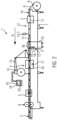
- thermoforming packaging machine 1 shows an intermittently operating thermoforming packaging machine 1 according to the invention.
- the thermoforming packaging machine 1 has a forming station 2, a vacuum cooling station 3, a sealing station 4, a cross-cutting device 5 and a longitudinal cutting device 6, which are arranged in this order in a transport direction R on a machine frame 7.
- a feed roller 8 On the input side there is a feed roller 8 on the machine frame 7, from which a bottom film 9 is removed.
- the thermoforming packaging machine 1 has a transport chain 10, which grips the bottom film 9 and transports it further in the transport direction R per main work cycle.
- the forming station 2 is designed as a deep-drawing station in which troughs 11 are formed in the lower film 9 by deep-drawing, for example using compressed air and/or vacuum.
- the forming station 2 can be designed in such a way that several troughs 11 are formed next to one another in the direction perpendicular to the transport direction R.
- An insertion section 12 is provided downstream of the forming station 2 in the transport direction R, in which the troughs 11 formed in the bottom film 9 are filled with products 13.
- the vacuum cooling station 3 has a hermetically sealable chamber 3a in which the atmosphere in the troughs 11 can be evacuated. To evacuate the chamber 3a, the vacuum cooling station 3 has a vacuum pump 16.
- Fig. 1 further shows that the vacuum cooling station 3 includes a protective gas device 17, which is designed to gas the vacuum-cooled products 13.
- the products 13 transported into the vacuum cooling station 3 can be both vacuum cooled and gas-flushed with a replacement gas or a gas mixture.
- the sealing station 4 has a hermetically sealable chamber 4a in which the atmosphere in the troughs 11 immediately before sealing with a top film 15 released from a top film receptacle 14, for example.
- B. can be evacuated and/or replaced by gas purging with a replacement gas or with a gas mixture.
- the cross-cutting device 5 can be designed as a punch that cuts through the lower film 9 and the upper film 15 in a direction transverse to the transport direction R between adjacent troughs 11.
- the cross-cutting device 5 works in such a way that the bottom film 9 is not cut across its entire width, so that the film is not cut through at least in an edge region. This enables controlled further transport through the transport chain 10.
- the longitudinal cutting device 6 can be designed as a knife arrangement with which the lower film 9 and the upper film 15 are cut between adjacent troughs 11 and on the lateral edge of the lower film 9 in the transport direction R, so that isolated packages V are present behind the longitudinal cutting device 6.
- the thermoforming packaging machine 1 also has a control 18. Its task is to control the processes taking place in the thermoforming packaging machine 1 at the work stations and to monitor.
- a display device 19 with operating elements 20 is used to visualize or influence the process sequences in the thermoforming packaging machine 1 for or by an operator.
- the vacuum cooling station 3 and the sealing station 4 are designed in the form of spatially separated work stations on the thermoforming packaging machine 1.
- the sealing station 4 has its own vacuum pump 21 for carrying out an evacuation process within the evacuation chamber 4a.
- the vacuum pump 16 of the vacuum cooling station 3 and the vacuum pump 21 of the sealing station 4 are therefore present as separate vacuum pumps 16, 21, which can be controlled separately from one another by means of the controller 18.
- FIG. 1 shows a dashed line that the vacuum cooling station 3 positioned upstream of the sealing station 4 can have two or even more evacuation chambers 3a for carrying out successive vacuum cooling processes. This allows the products 13 to be cooled particularly gently.
- FIG. 1 schematically that the vacuum cooling station 3 has a filter unit 22 through which filtered, germ-free air flows into the chamber 3a after vacuum cooling by means of a ventilation process.
- Fig. 1 also shows a temperature measuring unit 25 by means of which a product temperature T of the products 13 transported past underneath can be measured.
- a control 18 of the thermoforming packaging machine 1 an evacuation pressure and/or an evacuation pressure curve for the respective evacuation processes within the downstream vacuum cooling station 3 can be set, preferably automatically, with regard to the detected product temperature T.
- Fig. 2 shows the thermoforming packaging machine 1 Fig. 1 , wherein the vacuum cooling station 3 is configured in the form of a rollable carriage unit 23, which stands on the thermoforming packaging machine 1 upstream of the sealing station 4 in order to cool products 13 transported through it by means of an evacuation process before they reach the downstream sealing station 4.
- the carriage unit 23 forms a mobile module that is particularly suitable for flexible use on various types of thermoforming packaging machines, since its positioning between the insertion section 12 and the sealing station 4 can be freely selected.
- Fig. 3 shows the thermoforming packaging machine 1 with a vacuum cooling station 3 designed as a multi-chamber vacuum cooling station, which is positioned immediately upstream of the sealing station 4 in the transport direction R.
- the respective evacuation processes carried out one after the other within the chambers 3a of the vacuum cooling station 3 lead to a gradual, controlled vacuum cooling of the products 13 before they are transported into the sealing station 4 to close the troughs 11 with the top film 15.
- thermoforming packaging machine 1 has a capacitor 24 which is configured for the targeted removal of moisture.
- the condenser 24 can also be used in conjunction with the vacuum cooling station 3 Figure 1 and Figure 2 be used.
- An evacuation line 4b leads from the sealing station 4 to the condenser 24.
- Respective evacuation lines 3b also lead from the chambers 3a of the vacuum cooling station 3 to the condenser 24.
- the evacuation lines 3b, 4b are preferably designed to be heatable, so that a targeted separation of moisture only takes place at the condenser 24 the air evacuated from the chambers 3a, 4a.
- the present invention makes it possible to specifically cool hot-inserted products 13 along the insertion section 12 of the thermoforming packaging machine 1 to a desired temperature level by means of vacuum cooling, if necessary in stages using a multi-chamber cooling system, before they reach the sealing station 4, so that the sealing process carried out within the sealing station 4 is more economical and can be carried out with consistent packaging quality.
Landscapes
- Engineering & Computer Science (AREA)
- Mechanical Engineering (AREA)
- Chemical & Material Sciences (AREA)
- Dispersion Chemistry (AREA)
- Vacuum Packaging (AREA)
- Containers And Plastic Fillers For Packaging (AREA)
Abstract
Description
- Die Erfindung bezieht sich auf eine Tiefziehverpackungsmaschine gemäß dem Oberbegriff des Anspruchs 1. Weiter betrifft die Erfindung ein Verfahren gemäß dem Oberbegriff des Anspruchs 13.
- Derartige Tiefziehverpackungsmaschinen werden zum Herstellen von Verpackungen in Muldenform eingesetzt, wobei die darin verpackten Produkte entlang einer Einfüllstrecke der Tiefziehverpackungsmaschine in die hergestellten Mulden gefüllt werden und die befüllten Mulden im Anschluss daran in eine Siegelstation zum Versiegeln der Mulden transportiert werden.
- Sofern es sich bei den in die Mulden eingelegten Produkten um heiße Produkte, beispielsweise vorgekochte Maultaschen, handelt, können diese anhand eines innerhalb der Siegelstation durchgeführten Evakuierungsvorgangs geringfügig gekühlt werden. Es kann jedoch sein, dass der damit einhergehende Kühleffekt nicht ausreichend ist, um die Produkte vor dem Siegelvorgang auf ein gewünschtes Temperaturniveau abzukühlen, da die innerhalb der Siegelstation eingesetzte Evakuierungsphase nicht ausreichend lange andauert. Das Einschließen zu heißer Produkte kann aber dazu führen, dass sich unerwünscht innerhalb der versiegelten Verpackungen Niederschlag absetzt.
- Die
DE 296 07 689 U1 offenbart eine Tiefziehverpackungsmaschine mit einer Siegelstation, welcher in Transportrichtung eine mechanische Kühlvorrichtung nachgelagert ist, welche mittels daran montierter Kühlkissen von oben und unten auf versiegelte Verpackungen drückt, um diese nach dem Siegelprozess, stromabwärts der Siegelstation abzukühlen. -
JP S57-1021 A -
US 2004/0105927 A1 offenbart eine Tiefziehverpackungsmaschine mit einer Pasteurisierungsstation, die in Produktionsrichtung stromaufwärts einer Siegelstation der Verpackungsmaschine positioniert ist. Innerhalb der Pasteurisierungsstation können darin ankommende Produkte mittels Dampfzufuhr heißbehandelt werden. Optional findet im Anschluss an den Pasteurisierungsprozess ein Vakuum-Kühlvorgang statt. - Der Erfindung liegt die Aufgabe zugrunde, eine Tiefziehverpackungsmaschine sowie ein Verfahren zur Verfügung zu stellen, womit sich insbesondere heiß zu verpackende Produkte mit gleichbleibender Packungsqualität sowie gesteigerter Maschinenausbringungsrate verpacken lassen.
- Diese Aufgabe wird gelöst durch eine Tiefziehverpackungsmaschine gemäß Anspruch 1 sowie mittels eines Verfahrens gemäß Anspruch 13. Vorteilhafte Weiterbildungen der Erfindungen sind in den Unteransprüchen angegeben.
- Die erfindungsgemäße Tiefziehverpackungsmaschine umfasst eine Formstation zum Tiefziehen von Mulden in eine Folie, eine Einfüllstrecke zum Befüllen der Mulden mit Produkten sowie eine Siegelstation zum Versiegeln der Mulden. Erfindungsgemäß weist die Tiefziehverpackungsmaschine in Transportrichtung stromaufwärts der Siegelstation mindestens eine Vakuumkühlstation auf, die zum Vakuumkühlen der entlang der Einlegestrecke in die Mulden eingelegten Produkte ausgebildet ist. Heiß eingelegte Produkte können damit bereits an der Tiefziehverpackungsmaschine, an einer der Siegelstation in Transportrichtung vorgelagerten Stelle, auf ein gewünschtes (Vor-)Temperaturniveau vorgekühlt werden, bevor sie für den Siegelvorgang in die Siegelstation transportiert werden. Damit wird insbesondere erreicht, dass die entlang der Einlegestrecke heiß befüllten Produkte bereits vor Eintritt in die Siegelstation derart abgekühlt sind, dass der innerhalb der Siegelstation durchgeführte Evakuierungsvorgang lediglich eine reduzierte Kühlleistung zu erbringen braucht, um die Produkte vor dem Siegelvorgang auf ein gewünschtes Temperaturniveau zu bringen. Die aktiv gesteuerte Produktkühlung startet damit bei der Erfindung bereits vorderhalb der Siegelstation, innerhalb der erfindungsgemäßen, gesonderten Vakuumkühlstation. Somit können die Produkte auf besonders effiziente Art und Weise, präzise und hinsichtlich des Siegelvorgangs zeitlich abgestimmt auf ein vorbestimmtes Temperaturniveau gebracht werden.
- Vorzugsweise liegen die Vakuumkühlstation und die Siegelstation in Form von räumlich getrennt ausgebildeten Arbeitsstationen an der Tiefziehverpackungsmaschine vor und sind jeweils zum Ausbilden mindestens einer hermetisch verschließbaren Evakuierungskammer konfiguriert. Damit lässt sich das Abkühlen der heiß befüllten Produkte gezielt auf verschiedene Arbeitsstationen aufteilen, so dass durch die daran nacheinander erreichten Kühleffekte die Produkte besser auf ein gewünschtes Temperaturniveau abkühlbar sind.
- Eine Variante sieht vor, dass die Vakuumkühlstation mehrere hermetisch verschließbare Evakuierungskammern umfasst, die in Transportrichtung hintereinander angeordnet sind. Damit werden an der Tiefziehverpackungsmaschine gleich mehrere Evakuierungskammern stromaufwärts der Siegelstation eingesetzt, mittels welcher die daran hindurchgeführten Produkte stufenweise abkühlbar sind, so dass der Abkühlprozess auf mehrere Maschinenarbeitstakte aufgeteilt werden kann. Dies führt zu einer deutlich gesteigerten Maschinenausbringung mit gleichbleibender Packungsqualität. Damit lassen sich die Produkte vor allem besonders sanft, sprich pro Kühlkammer geringfügig, abkühlen.
- Vorteilhaft ist es, wenn die Vakuumkühlstation eine gesonderte Vakuumpumpe vorsieht. Damit ist gemeint, dass die Vakuumkühlstation den Evakuierungsvorgang unabhängig von anderen Arbeitsstationen der Tiefziehverpackungsmaschine durchführen kann, sozusagen als autark funktionierende Arbeitsstation vorliegt. Insbesondere ist damit der Betrieb der Vakuumpumpe der Vakuumkühlstation unabhängig vom Betrieb einer an der Siegelstation eingesetzten Vakuumpumpe, so dass der Abkühlprozess an der Vakuumkühlstation produktspezifisch besser steuerbar ist.
- Alternativ dazu wäre es vorstellbar, dass die an der Siegelstation und der Vakuumkühlstation ablaufenden Evakuierungsvorgänge zueinander zeitgleich mittels einer gemeinsamen Vakuumpumpe durchführbar sind. Die Siegelstation und die Vakuumkühlstation haben sozusagen dieselbe Vakuumpumpe.
- Eine bevorzugte Variante sieht vor, dass die Vakuumkühlstation mindestens eine Filtereinheit für einen Belüftungsvorgang aufweist. Die Belüftung der Vakuumkühlstation kann damit mittels gefilterter Luft geschehen, wodurch sich eine Keimbelastung des Produkts vermeiden lässt.
- Erfindungsgemäß sind die Siegelstation und die Vakuumkühlstation, insbesondere deren Kammerwände, auf ein vorbestimmtes Temperaturniveau beheizbar. Damit lässt sich gezielt ein Niederschlag von Feuchtigkeit an der Siegelstation und der Vakuumkühlstation verhindern, zumindest jedoch reduzieren.
- Vorzugsweise weist die Tiefziehverpackungsmaschine mindestens einen Kondensator zum gezielten Abführen von Feuchtigkeit auf. Beispielsweise lässt sich mittels des Kondensators gezielt Feuchtigkeit aus der evakuierten Luft der Siegelstation und/oder der Vakuumkühlstation abscheiden, was insbesondere zu einer hygienischen Arbeitsweise der Tiefziehverpackungsmaschine führt. Vorstellbar ist es, dass die Siegelstation und/oder die Vakuumkühlstation über beheizte Leitungen Evakuierungsluft aus den jeweiligen Evakuierungskammern zu dem Kondensator leiten, an welchem die Feuchtigkeit aus der erwärmten Evakuierungsluft abgeschieden werden kann.
- Vorzugsweise ist die Vakuumkühlstation an einem Maschinengestell der Tiefziehverpackungsmaschine stromaufwärts der Siegelstation, wahlweise an verschiedenen Positionen, befestigbar. Damit ist die Vakuumkühlstation flexibel zum Vorkühlen unterschiedlich heiß befüllter Produkte besser einsetzbar. Eine Variante sieht am Maschinengestell eine Linearführung vor, an welcher die Vakuumkühlstation in Transportrichtung verschiebbar gelagert ist.
- Eine besonders vorteilhafte Variante sieht vor, dass die Vakuumkühlstation in Form einer rollbaren Wageneinheit konfiguriert ist, die an der Tiefziehverpackungsmaschine, insbesondere an deren Maschinengestell, temporär ortsfest positionierbar ist. Dies ermöglicht einen mobilen Einsatz der Vakuumkühlstation an der Tiefziehverpackungsmaschine. Die Vakuumkühlstation in Form einer rollbaren Wageneinheit eignet sich besonders gut für Service- sowie Reinigungszwecke.
- Zum Vorbehandeln der befüllten Produkte kann die Vakuumkühlstation eine Schutzgaseinrichtung aufweisen, die zum anschließenden Begasen der darin vakuumgekühlten Produkte ausgebildet ist. Damit lassen sich die befüllten Produkte für den Weitertransport mit einer Art Gashülle versehen.
- Vorzugsweise ist ein Öffnen und Schließen der Vakuumkühlstation mit einem Öffnen und Schlie-ßen der in Transportrichtung stromabwärts positionierten Siegelstation synchonisierbar. Vorstellbar wäre es, dass das Öffnen und Schließen der Vakuumkühlstation vom Öffnen und Schließen der Siegelstation getriggert wird.
- Vorzugsweise weist die Tiefziehverpackungsmaschine eine Steuerung zum Steuern und Überwachen der an der Vakuumkühlstation ablaufenden Prozesse auf, unabhängig davon in welcher Form die Vakuumkühlstation und/oder an welcher Stelle die Vakuumkühlstation stromaufwärts der Siegelstation an der Tiefziehverpackungsmaschine vorliegt. Dabei kann es sich insbesondere um dieselbe Steuerung handeln, die auch zum Steuern anderer Arbeitsstationen der Tiefziehverpackungsmaschine, beispielsweise der Siegelstation und/oder der eingangs am Maschinengestell positionierten Formstation zur Herstellung der Mulden, vorgesehen ist.
- Eine Variante sieht vor, dass hinsichtlich einer entlang der Einlegestrecke erfassten Produkttemperatur ein an der Vakuumkühlstation variierbarer Evakuierungsdruck aktivierbar und/oder ein darin ablaufender Evakuierungsdruckverlauf, beispielsweise in Form einer gesteuerten Druckkurve, steuerbar ist. Damit lässt sich der Kühlvorgang innerhalb der Vakuumkühlstation angesichts gemessener Produkttemperaturen produktspezifisch durchführen, sodass innerhalb der Siegelstation Produkte mit einheitlicher Produkttemperatur versiegelt werden können. In anderen Worten lassen sich somit die Produkte mit einer gewünschten Produkttemperatur der Siegelstation zuführen, damit darin Verpackungen mit gleichbleibender Produktqualität versiegelt werden können. Vorstellbar ist es, dass die Vakuumkühlstation eine Temperaturmesseinheit, beispielsweise in Form eines Temperatursensors oder einer Wärmebildkamera, aufweist, mittels welcher die Produkttemperatur eines unmittelbar vor der Vakuumkühlstation bereitstehenden Produkts erfassbar ist, worauf basierend der Evakuierungsvorgang steuerbar ist. Die Temperaturmesseinheit kann alternativ dazu als separate Einheit stromaufwärts der Vakuumkühlstation vorliegen.
- Die Erfindung bezieht sich auch auf ein Verfahren zum Kühlen von Produkten, die entlang einer Einfüllstrecke einer Tiefziehverpackungsmaschine in Mulden eingelegt werden. Erfindungsgemäß werden die in Mulden eingelegten Produkte außerhalb einer Siegelstation, innerhalb einer in Transportrichtung der Siegelstation vorgelagerten Vakuumkühlstation der Tiefziehverpackungsmaschine mittels eines daran gesteuerten Evakuierungsvorgangs abgekühlt. Damit erreichen die in Mulden eingelegten Produkte bereits außerhalb der Siegelstation ein reduziertes Temperaturniveau, von welchem ausgehend sich durch die innerhalb der Siegelstation durchgeführten anschließenden Prozesse besser Verpackungen mit gleichbleibender Qualität herstellen lassen. Das aktiv innerhalb der Vakuumkühlstation gesteuerte Kühlen der Produkte stromaufwärts der Siegelstation führt bereits zu einem zumindest anteiligen Kühleffekt, welcher die anschließend innerhalb der Siegelstation ablaufenden Prozesse begünstigt. Insbesondere können die Produkte bis zur Durchführung des Siegelvorgangs präzise auf ein gewünschtes Temperaturniveau gebracht werden.
- Im Folgenden werden vorteilhafte Ausführungsbeispiele der Erfindung anhand von Zeichnungen näher erläutert. Im Einzelnen zeigen:
- Figur 1
- eine Tiefziehverpackungsmaschine mit einer Vakuumkühlstation,
- Figur 2
- eine Tiefziehverpackungsmaschine mit einer Vakuumkühlstation in Form einer Wageneinheit, und
- Figur 3
- eine Tiefziehverpackungsmaschine mit einer Mehrkammer-Vakuumkühlstation.
- Gleiche Komponenten sind in den Figuren durchgängig mit gleichen Bezugszeichen versehen.
-
Fig. 1 zeigt eine erfindungsgemäße, intermittierend arbeitende Tiefziehverpackungsmaschine 1. Die Tiefziehverpackungsmaschine 1 weist eine Formstation 2, eine Vakuumkühlstation 3, eine Siegelstation 4, eine Querschneideeinrichtung 5 und eine Längsschneideeinrichtung 6 auf, die in dieser Reihenfolge in einer Transportrichtung R an einem Maschinengestell 7 angeordnet sind. Eingangsseitig befindet sich an dem Maschinengestell 7 eine Zuführrolle 8, von der eine Unterfolie 9 abgezogen wird. Ferner weist die Tiefziehverpackungsmaschine 1 eine Transportkette 10 auf, die die Unterfolie 9 ergreift und diese pro Hauptarbeitstakt in der Transportrichtung R weitertransportiert. - In der dargestellten Ausführungsform gemäß
Fig. 1 ist die Formstation 2 als eine Tiefziehstation ausgebildet, in der durch Tiefziehen, beispielsweise mittels Druckluft und/oder Vakuum, Mulden 11 in der Unterfolie 9 geformt werden. Dabei kann die Formstation 2 derart ausgebildet sein, dass in der Richtung senkrecht zur Transportrichtung R mehrere Mulden 11 nebeneinander gebildet werden. In Transportrichtung R der Formstation 2 nachgeordnet ist eine Einlegestrecke 12 vorgesehen, in welcher die in der Unterfolie 9 geformten Mulden 11 mit Produkten 13 befüllt werden. - Die Vakuumkühlstation 3 verfügt über eine hermetisch verschließbare Kammer 3a, in der die Atmosphäre in den Mulden 11 evakuiert werden kann. Zum Evakuieren der Kammer 3a weist die Vakuumkühlstation 3 eine Vakuumpumpe 16 auf.
-
Fig. 1 zeigt weiter, dass die Vakuumkühlstation 3 eine Schutzgaseinrichtung 17 umfasst, die zum Begasen der vakuumgekühlten Produkte 13 ausgebildet ist. Somit können die in die Vakuumkühlstation 3 hineintransportierten Produkte 13 sowohl vakuumgekühlt, als auch mit einem Austauschgas oder einem Gasgemisch gasbespült werden. - Die Siegelstation 4 verfügt über eine hermetisch verschließbare Kammer 4a, in der die Atmosphäre in den Mulden 11 unmittelbar vor dem Versiegeln mit einer von einer Oberfolienaufnahme 14 abgegebenen Oberfolie 15 z. B. evakuiert und/oder durch Gasspülen mit einem Austauschgas oder mit einem Gasgemisch ersetzt werden kann.
- Die Querschneideeinrichtung 5 kann als Stanze ausgebildet sein, die die Unterfolie 9 und die Oberfolie 15 in einer Richtung quer zur Transportrichtung R zwischen benachbarten Mulden 11 durchtrennt. Dabei arbeitet die Querschneideeinrichtung 5 derart, dass die Unterfolie 9 nicht auf der gesamten Breite aufgetrennt wird, so dass zumindest in einem Randbereich die Folie nicht durchtrennt wird. Dies ermöglicht einen kontrollierten Weitertransport durch die Transportkette 10.
- Die Längsschneideeinrichtung 6 kann als eine Messeranordnung ausgebildet sein, mit der die Unterfolie 9 und die Oberfolie 15 zwischen benachbarten Mulden 11 und am seitlichen Rand der Unterfolie 9 in Transportrichtung R durchtrennt werden, so dass hinter der Längsschneideeinrichtung 6 vereinzelte Verpackungen V vorliegen.
- Die Tiefziehverpackungsmaschine 1 verfügt ferner über eine Steuerung 18. Sie hat die Aufgabe, die in der Tiefziehverpackungsmaschine 1 ablaufenden Prozesse an den Arbeitsstationen zu steuern und zu überwachen. Eine Anzeigevorrichtung 19 mit Bedienelementen 20 dient zum Visualisieren bzw. Beeinflussen der Prozessabläufe in der Tiefziehverpackungsmaschine 1 für bzw. durch einen Bediener.
- Gemäß
Fig. 1 sind die Vakuumkühlstation 3 und die Siegelstation 4 in Form von räumlich getrennt voneinander ausgebildeten Arbeitsstationen an der Tiefziehverpackungsmaschine 1 ausgebildet. Gegenüber der Vakuumkühlstation 3 weist die Siegelstation 4 eine eigene Vakuumpumpe 21 zum Durchführen eines Evakuierungsvorgangs innerhalb der Evakuierungskammer 4a auf. Die Vakuumpumpe 16 der Vakuumkühlstation 3 und die Vakuumpumpe 21 der Siegelstation 4 liegen somit als gesonderte Vakuumpumpen 16, 21 vor, die mittels der Steuerung 18 getrennt voneinander ansteuerbar sind. - Weiter zeigt
Fig. 1 in gestrichelter Darstellung, dass die stromaufwärts der Siegelstation 4 positionierte Vakuumkühlstation 3 zwei oder sogar noch mehr Evakuierungskammern 3a zum Durchführen aufeinanderfolgender Vakuumkühlprozesse aufweisen kann. Damit können die Produkte 13 besonders sanft abgekühlt werden. - Weiterhin zeigt
Fig. 1 schematisch, dass die Vakuumkühlstation 3 eine Filtereinheit 22 aufweist, durch die nach dem Vakuumkühlen mittels eines Belüftungsvorgangs gefilterte, keimfreie Luft in die Kammer 3a einströmt. -
Fig. 1 zeigt auch eine Temperaturmesseinheit 25 mittels welcher eine Produkttemperatur T der darunter vorbeitransportierten Produkte 13 messbar ist. Anhand der Steuerung 18 der Tiefziehverpackungsmaschine 1 lassen sich hinsichtlich der erfassten Produkttemperatur T ein Evakuierungsdruck und/oder ein Evakuierungsdruckverlauf für die jeweiligen Evakuierungsvorgänge innerhalb der nachgelagerten Vakuumkühlstation 3 vorzugsweise automatisiert einstellen. -
Fig. 2 zeigt die Tiefziehverpackungsmaschine 1 ausFig. 1 , wobei die Vakuumkühlstation 3 in Form einer rollbaren Wageneinheit 23 konfiguriert ist, die an der Tiefziehverpackungsmaschine 1 stromaufwärts der Siegelstation 4 steht, um daran hindurchtransportierte Produkte 13 mittels eines Evakuierungsvorgangs zu kühlen, bevor sie die stromabwärts nachgelagerte Siegelstation 4 erreichen. Die Wageneinheit 23 bildet ein fahrbares Modul, das sich besonders gut für einen flexiblen Einsatz an verschiedenen Tiefziehverpackungsmaschinentypen eignet, da seine Positionierung zwischen der Einlegestrecke 12 und der Siegelstation 4 frei wählbar ist. -
Fig. 3 zeigt die Tiefziehverpackungsmaschine 1 mit einer als Mehrkammer-Vakuumkühlstation ausgebildeten Vakuumkühlstation 3, die in Transportrichtung R unmittelbar stromaufwärts der Siegelstation 4 positioniert ist. Die jeweiligen innerhalb der Kammern 3a der Vakuumkühlstation 3 nacheinander durchgeführten Evakuierungsvorgänge führen zu einer stufenweisen, gesteuerten Vakuumkühlung der Produkte 13, bevor diese zum Verschließen der Mulden 11 mit der Oberfolie 15 in die Siegelstation 4 transportiert werden. - Gemäß
Fig. 3 sind die Vakuumkühlstation 3 und die Siegelstation 4 als unmittelbar benachbarte Arbeitsstationen ausgebildet, wobei für beide sogar ein integraler Aufbau vorstellbar ist.Fig. 3 zeigt auch, dass die Tiefziehverpackungsmaschine 1 einen Kondensator 24 aufweist, der zum gezielten Abführen von Feuchtigkeit konfiguriert ist. Der Kondensator 24 kann auch in Zusammenhang mit der Vakuumkühlstation 3 ausFigur 1 undFigur 2 eingesetzt werden. - Von der Siegelstation 4 führt eine Evakuierungsleitung 4b zum Kondensator 24. Ebenfalls führen von den Kammern 3a der Vakuumkühlstation 3 jeweilige Evakuierungsleitungen 3b zum Kondensator 24. Die Evakuierungsleitungen 3b, 4b sind vorzugsweise beheizbar ausgebildet, so dass erst am Kondensator 24 ein gezieltes Abscheiden von Feuchtigkeit aus der aus den Kammern 3a, 4a evakuierten Luft geschieht.
- Die vorliegende Erfindung ermöglicht es, entlang der Einlegestrecke 12 der Tiefziehverpackungsmaschine 1 heiß eingelegte Produkte 13 mittels Vakuumkühlens, ggf. stufenartig durch ein Mehrkammerkühlsystem, gezielt auf ein gewünschtes Temperaturniveau abzukühlen, bevor diese die Siegelstation 4 erreichen, damit der innerhalb der Siegelstation 4 durchgeführte Siegelvorgang wirtschaftlicher und mit gleichbleibender Verpackungsqualität durchgeführt werden kann.
Claims (14)
- Tiefziehverpackungsmaschine (1) mit einer Formstation (2) zum Tiefziehen von Mulden (11) in eine Folie (9), einer Einfüllstrecke (12) zum Befüllen von Produkten (13) in die Mulden (11) und mit einer Siegelstation (4) zum Versiegeln der Mulden (11), wobei die Tiefziehverpackungsmaschine (1) in Transportrichtung (R) stromaufwärts der Siegelstation (4) mindestens eine Vakuumkühlstation (3) aufweist, die zum Vakuumkühlen der entlang der Einfüllstrecke (12) in die Mulden (11) eingelegten Produkte (13) ausgebildet ist, dadurch gekennzeichnet, dass die Siegelstation (4) und die Vakuumkühlstation (3) auf ein vorbestimmtes Temperaturniveau beheizbar sind.
- Tiefziehverpackungsmaschine nach Anspruch 1, dadurch gekennzeichnet, dass die Vakuumkühlstation (3) und die Siegelstation (4) in Form von räumlich getrennt ausgebildeten Arbeitsstationen an der Tiefziehverpackungsmaschine (1) vorliegen und jeweils zum Ausbilden mindestens einer hermetisch verschließbaren Evakuierungskammer (3a, 4a) konfiguriert sind.
- Tiefziehverpackungsmaschine nach Anspruch 1 oder 2, dadurch gekennzeichnet, dass die Vakuumkühlstation (3) mehrere hermetisch verschließbare Evakuierungskammern (3a) umfasst, die in Transportrichtung (R) hintereinander angeordnet sind.
- Tiefziehverpackungsmaschine nach einem der vorangehenden Ansprüche, dadurch gekennzeichnet, dass die Vakuumkühlstation (3) eine gesonderte Vakuumpumpe (16) vorsieht.
- Tiefziehverpackungsmaschine nach einem der vorangehenden Ansprüche, dadurch gekennzeichnet, dass die Vakuumkühlstation (3) mindestens eine Filtereinheit (22) für einen Belüftungsvorgang aufweist.
- Tiefziehverpackungsmaschine nach einem der vorangehenden Ansprüche, dadurch gekennzeichnet, dass die Tiefziehverpackungsmaschine (1) mindestens einen Kondensator (24) zum gezielten Abführen von Feuchtigkeit aufweist.
- Tiefziehverpackungsmaschine nach einem der vorangehenden Ansprüche, dadurch gekennzeichnet, dass die Vakuumkühlstation (3) an einem Maschinengestell (7) der Tiefziehverpackungsmaschine (1) stromaufwärts der Siegelstation (4) an verschiedenen Positionen befestigbar ist.
- Tiefziehverpackungsmaschine nach einem der vorangehenden Ansprüche, dadurch gekennzeichnet, dass die Vakuumkühlstation (3) in Form einer rollbaren Wageneinheit (23) konfiguriert ist, die an der Tiefziehverpackungsmaschine (1) ortsfest positionierbar ist.
- Tiefziehverpackungsmaschine nach einem der vorangehenden Ansprüche, dadurch gekennzeichnet, dass die Vakuumkühlstation (3) eine Schutzgaseinrichtung (17) aufweist, die zum Begasen der vakuumgekühlten Produkte (13) ausgebildet ist.
- Tiefziehverpackungsmaschine nach einem der vorangehenden Ansprüche, dadurch gekennzeichnet, dass ein Öffnen und Schließen der Vakuumkühlstation (3) mit einem Öffnen und Schließen der in Transportrichtung (R) stromabwärts positionierten Siegelstation (4) synchronisierbar ist.
- Tiefziehverpackungsmaschine nach einem der vorangehenden Ansprüche, dadurch gekennzeichnet, dass die Tiefziehverpackungsmaschine (1) eine Steuerung (18) zum Steuern und Überwachen der an der Vakuumkühlstation (3) ablaufenden Prozesse aufweist.
- Tiefziehverpackungsmaschine nach einem der vorangehenden Ansprüche, dadurch gekennzeichnet, dass hinsichtlich einer entlang der Einlegestrecke (12) erfassten Produkttemperatur (T) ein Evakuierungsdruck und/oder ein Evakuierungsdruckverlauf aktivierbar ist.
- Verfahren zum Kühlen von Produkten (13), die entlang einer Einfüllstrecke (12) einer Tiefziehverpackungsmaschine (1) in Mulden (11) eingelegt werden, dadurch gekennzeichnet, dass die in Mulden (11) eingelegten Produkte (13) außerhalb einer auf ein vorbestimmtes Temperaturniveau beheizten Siegelstation (4), innerhalb einer in Transportrichtung (R) der Siegelstation (4) vorgelagerten, auf ein vorbestimmtes Temperaturniveau beheizten Vakuumkühlstation (3) der Tiefziehverpackungsmaschine (1) anhand eines daran gesteuerten Vakuumkühlvorgangs abgekühlt werden.
- Verfahren nach Anspruch 13, dadurch gekennzeichnet, dass die in Mulden (11) eingelegten Produkte (13) jeweils gemäß einem Maschinenarbeitstakt der Tiefziehverpackungsmaschine (1) mehrere in Transportrichtung (R) hintereinander angeordnete Evakuierungskammern (3a) an der Vakuumkühlstation (3) durchlaufen, um stufenweise abgekühlt zu werden.
Applications Claiming Priority (2)
| Application Number | Priority Date | Filing Date | Title |
|---|---|---|---|
| DE102020201284.9A DE102020201284A1 (de) | 2020-02-03 | 2020-02-03 | Tiefziehverpackungsmaschine mit Vakuumkühlstation und Verfahren zum Vakuumkühlen heißverpackter Produkte |
| EP20214878.9A EP3858749A1 (de) | 2020-02-03 | 2020-12-17 | Tiefziehverpackungsmaschine mit vakuumkühlstation und verfahren zum vakuumkühlen heissverpackter produkte |
Related Parent Applications (1)
| Application Number | Title | Priority Date | Filing Date |
|---|---|---|---|
| EP20214878.9A Division EP3858749A1 (de) | 2020-02-03 | 2020-12-17 | Tiefziehverpackungsmaschine mit vakuumkühlstation und verfahren zum vakuumkühlen heissverpackter produkte |
Publications (2)
| Publication Number | Publication Date |
|---|---|
| EP4335759A2 true EP4335759A2 (de) | 2024-03-13 |
| EP4335759A3 EP4335759A3 (de) | 2024-06-26 |
Family
ID=73855258
Family Applications (2)
| Application Number | Title | Priority Date | Filing Date |
|---|---|---|---|
| EP20214878.9A Pending EP3858749A1 (de) | 2020-02-03 | 2020-12-17 | Tiefziehverpackungsmaschine mit vakuumkühlstation und verfahren zum vakuumkühlen heissverpackter produkte |
| EP24153268.8A Pending EP4335759A3 (de) | 2020-02-03 | 2020-12-17 | Tiefziehverpackungsmaschine mit vakuumkühlstation und verfahren zum vakuumkühlen heissverpackter produkte |
Family Applications Before (1)
| Application Number | Title | Priority Date | Filing Date |
|---|---|---|---|
| EP20214878.9A Pending EP3858749A1 (de) | 2020-02-03 | 2020-12-17 | Tiefziehverpackungsmaschine mit vakuumkühlstation und verfahren zum vakuumkühlen heissverpackter produkte |
Country Status (4)
| Country | Link |
|---|---|
| US (1) | US11511902B2 (de) |
| EP (2) | EP3858749A1 (de) |
| CN (1) | CN113200179B (de) |
| DE (1) | DE102020201284A1 (de) |
Cited By (3)
| Publication number | Priority date | Publication date | Assignee | Title |
|---|---|---|---|---|
| DE102024112741B3 (de) | 2024-05-07 | 2025-06-18 | Multivac Sepp Haggenmüller Se & Co. Kg | Vorrichtung und Verfahren zum Kontinuierlichen Vakuumkühlen |
| DE102024112738B3 (de) | 2024-05-07 | 2025-07-03 | Multivac Sepp Haggenmüller Se & Co. Kg | Verfahren sowie Kühlstraße zum Vakuumkühlen heißer Produkte |
| DE102024112737B3 (de) | 2024-05-07 | 2025-09-11 | Multivac Sepp Haggenmüller Se & Co. Kg | Verpackungsmaschine und Verfahren zum Vakuumkühlen |
Families Citing this family (2)
| Publication number | Priority date | Publication date | Assignee | Title |
|---|---|---|---|---|
| DE102024112740B3 (de) | 2024-05-07 | 2025-06-18 | Multivac Sepp Haggenmüller Se & Co. Kg | Vakuumkühlvorrichtung sowie Verfahren zum Vakuumkühlen eines Produkts |
| DE102024112739A1 (de) | 2024-05-07 | 2025-11-13 | Multivac Sepp Haggenmüller Se & Co. Kg | Vorrichtung und Verfahren zum Vakuumkühlen von Produkten |
Citations (3)
| Publication number | Priority date | Publication date | Assignee | Title |
|---|---|---|---|---|
| JPS571021A (en) | 1980-05-28 | 1982-01-06 | Omori Machinery | Vacuum packing method |
| DE29607689U1 (de) | 1996-04-27 | 1996-07-18 | Tetra Laval Convenience Food GmbH & Co. KG, 35216 Biedenkopf | Kühleinrichtung |
| US20040105927A1 (en) | 2002-09-13 | 2004-06-03 | Karman Vernon D. | Surface pasteurization method |
Family Cites Families (24)
| Publication number | Priority date | Publication date | Assignee | Title |
|---|---|---|---|---|
| CH453186A (de) * | 1965-12-15 | 1968-06-14 | Hoefliger & Karg | Maschine zum Herstellen, Füllen und Verschliessen von Tiefziehpackungen |
| SE7805165L (sv) * | 1977-05-10 | 1978-11-11 | Gatrun Anstalt | Forfarande och anordning for behandling av en produkt i steril miljo |
| DE2829889A1 (de) * | 1978-07-07 | 1980-01-24 | Leybold Heraeus Gmbh & Co Kg | Verfahren und vorrichtung zur wiederholten evakuierung abgeschlossener volumina |
| DE2930963C2 (de) * | 1979-07-31 | 1984-01-12 | Krämer & Grebe GmbH & Co KG Maschinen- und Modellfabrik, 3560 Biedenkopf | Verpackungsvorrichtung |
| US5088293A (en) * | 1990-08-30 | 1992-02-18 | The Japan Steel Works, Ltd. | Vacuum cooling method and apparatus |
| US5458899A (en) * | 1990-09-05 | 1995-10-17 | Weyerhaeuser Company | Method of packaging perishable food or horticultural products |
| US5895626A (en) * | 1994-09-01 | 1999-04-20 | Nishirei Corporation | Sterilizing method, apparatus and container of solid matter or liquid matter containing solid matter |
| JPH0958613A (ja) | 1995-08-11 | 1997-03-04 | Ajikan:Kk | 加工食品の真空包装方法及びその装置 |
| JPH09207908A (ja) | 1996-02-02 | 1997-08-12 | Chubu Corp:Kk | 真空包装装置および真空包装方法 |
| JP2002017318A (ja) * | 2000-06-30 | 2002-01-22 | Koumura Techno:Kk | 固体食品の加熱殺菌方法及びその包装容器 |
| DE10154722A1 (de) * | 2001-11-09 | 2003-05-22 | Convenience Food Sys Wallau | Verpackungsmaschine |
| JP2004132594A (ja) * | 2002-10-10 | 2004-04-30 | Miura Co Ltd | 真空冷却方法および真空冷却装置 |
| US8784920B2 (en) * | 2006-12-29 | 2014-07-22 | St. Dalfour Sas | System and method for packaging |
| ES2345060T3 (es) * | 2007-03-21 | 2010-09-14 | Opus Industry Sa | Esterilizacion de liquidos en unos recipientes hermeticamente cerrados. |
| DE102009020898B4 (de) * | 2009-05-13 | 2014-05-28 | Multivac Sepp Haggenmüller Gmbh & Co. Kg | Tiefziehverpackungsmaschine für mehrlagige Deckelfolie |
| CN103492270B (zh) * | 2011-01-27 | 2015-07-15 | Cfs德国股份有限公司 | 包装机和用于形成真空和/或充气包装的方法 |
| CN202624688U (zh) | 2012-05-31 | 2012-12-26 | 上海理工大学 | 一种带真空预冷功能的气调保鲜包装机 |
| ES2528011T3 (es) * | 2012-07-24 | 2015-02-03 | Multivac Sepp Haggenmüller Gmbh & Co. Kg | Procedimiento de evacuación para máquina de envasado |
| JP6052729B2 (ja) * | 2012-10-12 | 2016-12-27 | 大分県 | 青果物の鮮度保持方法、青果物包装品、青果物包装方法、包装機及び包装システム |
| GB201602597D0 (en) * | 2016-02-12 | 2016-03-30 | Martel Scarlett | Method of preserving produce by packaging using cold and low pressure nitrogen gas |
| DE102016118295A1 (de) * | 2016-09-28 | 2018-03-29 | Multivac Sepp Haggenmüller Se & Co. Kg | Verfahren für Tiefziehverpackungsmaschine |
| JP2018118741A (ja) | 2017-01-23 | 2018-08-02 | 株式会社Tosei | 真空包装装置 |
| JP6715222B2 (ja) * | 2017-09-22 | 2020-07-01 | 株式会社日阪製作所 | 包装食品の製造方法 |
| EP3491926A1 (de) * | 2017-11-30 | 2019-06-05 | Due Bi Automazioni Di Benetollo Luigi | Verbessertes verfahren zur lagerung von lebensmitteln |
-
2020
- 2020-02-03 DE DE102020201284.9A patent/DE102020201284A1/de active Pending
- 2020-12-17 EP EP20214878.9A patent/EP3858749A1/de active Pending
- 2020-12-17 EP EP24153268.8A patent/EP4335759A3/de active Pending
-
2021
- 2021-01-29 CN CN202110143923.2A patent/CN113200179B/zh active Active
- 2021-01-29 US US17/162,164 patent/US11511902B2/en active Active
Patent Citations (3)
| Publication number | Priority date | Publication date | Assignee | Title |
|---|---|---|---|---|
| JPS571021A (en) | 1980-05-28 | 1982-01-06 | Omori Machinery | Vacuum packing method |
| DE29607689U1 (de) | 1996-04-27 | 1996-07-18 | Tetra Laval Convenience Food GmbH & Co. KG, 35216 Biedenkopf | Kühleinrichtung |
| US20040105927A1 (en) | 2002-09-13 | 2004-06-03 | Karman Vernon D. | Surface pasteurization method |
Cited By (5)
| Publication number | Priority date | Publication date | Assignee | Title |
|---|---|---|---|---|
| DE102024112741B3 (de) | 2024-05-07 | 2025-06-18 | Multivac Sepp Haggenmüller Se & Co. Kg | Vorrichtung und Verfahren zum Kontinuierlichen Vakuumkühlen |
| DE102024112738B3 (de) | 2024-05-07 | 2025-07-03 | Multivac Sepp Haggenmüller Se & Co. Kg | Verfahren sowie Kühlstraße zum Vakuumkühlen heißer Produkte |
| DE102024112737B3 (de) | 2024-05-07 | 2025-09-11 | Multivac Sepp Haggenmüller Se & Co. Kg | Verpackungsmaschine und Verfahren zum Vakuumkühlen |
| EP4647687A1 (de) | 2024-05-07 | 2025-11-12 | MULTIVAC Sepp Haggenmüller SE & Co. KG | Verpackungsmaschine und verfahren zum vakuumkühlen |
| EP4647688A1 (de) | 2024-05-07 | 2025-11-12 | MULTIVAC Sepp Haggenmüller SE & Co. KG | Verfahren sowie kühlstrasse zum vakuumkühlen heisser produkte |
Also Published As
| Publication number | Publication date |
|---|---|
| US20210237920A1 (en) | 2021-08-05 |
| US11511902B2 (en) | 2022-11-29 |
| CN113200179A (zh) | 2021-08-03 |
| EP3858749A1 (de) | 2021-08-04 |
| DE102020201284A1 (de) | 2021-08-05 |
| EP4335759A3 (de) | 2024-06-26 |
| CN113200179B (zh) | 2025-07-15 |
Similar Documents
| Publication | Publication Date | Title |
|---|---|---|
| EP3858749A1 (de) | Tiefziehverpackungsmaschine mit vakuumkühlstation und verfahren zum vakuumkühlen heissverpackter produkte | |
| EP2769923B1 (de) | Tiefziehverpackungsmaschine mit Siegelstation und Verfahren | |
| EP2484594B1 (de) | Verpackungsmaschine zum Herstellen einer Mehrlagenpackung | |
| EP2766262B1 (de) | Tiefziehverpackungsmaschine | |
| EP2896573B1 (de) | Tiefziehverpackungsmaschine mit Oberfolienformstation und entsprechendes Verfahren | |
| EP2551203B1 (de) | Verfahren zum Schneiden von Packungen | |
| EP0710605B1 (de) | Verfahren und Vorrichtung zum Maximieren der Taktgeschwindigkeit einer Vakuumverpackungsmaschine | |
| EP2522580A1 (de) | Werkzeugwechseleinrichtung | |
| EP2251265A2 (de) | Verpackungsmaschine für mehrlagige Deckelfolie | |
| EP2574431A1 (de) | Komplettschnittstation und Verfahren zum Vereinzeln von Verpackungen | |
| EP4082924B1 (de) | Siegelmaschine zum versiegeln von verpackungen | |
| EP3539883B1 (de) | Tiefziehverpackungsmaschine mit folienumlenkung | |
| EP3088315B2 (de) | Tiefziehverpackungsmaschine mit streifenstanze | |
| WO2005073087A1 (de) | Verfahren und vorrichtung zum herstellen und befüllen von behältern | |
| EP4234418B1 (de) | Verpackungsmaschine oder verpackungslinie mit dynamischem rezeptwechsel | |
| EP4163216B1 (de) | Saugdüse | |
| EP3295800A1 (de) | Sandwichkeksvorrichtung | |
| EP4249381A1 (de) | Tiefziehverpackungsmaschine mit querschneidestation | |
| EP1806290B1 (de) | Verpackungsmaschine | |
| DE102024112737B3 (de) | Verpackungsmaschine und Verfahren zum Vakuumkühlen | |
| WO2025233251A1 (de) | Vorrichtung und verfahren zum vakuumkühlen von produkten | |
| EP4019416B1 (de) | Siegelstation mit fliehkraftabscheider | |
| EP4725850A2 (de) | Vorrichtung sowie verfahren zum begasen einer mit einem mikrowellengegarten produkt befüllten verpackung mit einem schutzgas | |
| EP1340687A2 (de) | Einrichtung zum Herstellen schlauchförmiger Beutel | |
| DE102018111600A1 (de) | Verfahren zum erkennen von leckagen |
Legal Events
| Date | Code | Title | Description |
|---|---|---|---|
| PUAI | Public reference made under article 153(3) epc to a published international application that has entered the european phase |
Free format text: ORIGINAL CODE: 0009012 |
|
| STAA | Information on the status of an ep patent application or granted ep patent |
Free format text: STATUS: THE APPLICATION HAS BEEN PUBLISHED |
|
| AC | Divisional application: reference to earlier application |
Ref document number: 3858749 Country of ref document: EP Kind code of ref document: P |
|
| AK | Designated contracting states |
Kind code of ref document: A2 Designated state(s): AL AT BE BG CH CY CZ DE DK EE ES FI FR GB GR HR HU IE IS IT LI LT LU LV MC MK MT NL NO PL PT RO RS SE SI SK SM TR |
|
| REG | Reference to a national code |
Ref country code: DE Ref legal event code: R079 Free format text: PREVIOUS MAIN CLASS: B65B0025000000 Ipc: B65B0063080000 |
|
| PUAL | Search report despatched |
Free format text: ORIGINAL CODE: 0009013 |
|
| AK | Designated contracting states |
Kind code of ref document: A3 Designated state(s): AL AT BE BG CH CY CZ DE DK EE ES FI FR GB GR HR HU IE IS IT LI LT LU LV MC MK MT NL NO PL PT RO RS SE SI SK SM TR |
|
| RIC1 | Information provided on ipc code assigned before grant |
Ipc: B65B 25/00 20060101ALI20240517BHEP Ipc: A23L 3/36 20060101ALI20240517BHEP Ipc: B65B 57/16 20060101ALI20240517BHEP Ipc: B65B 59/04 20060101ALI20240517BHEP Ipc: B65B 7/16 20060101ALI20240517BHEP Ipc: B65B 31/02 20060101ALI20240517BHEP Ipc: B65B 9/04 20060101ALI20240517BHEP Ipc: B65B 63/08 20060101AFI20240517BHEP |
|
| STAA | Information on the status of an ep patent application or granted ep patent |
Free format text: STATUS: REQUEST FOR EXAMINATION WAS MADE |
|
| 17P | Request for examination filed |
Effective date: 20240724 |
|
| RBV | Designated contracting states (corrected) |
Designated state(s): AL AT BE BG CH CY CZ DE DK EE ES FI FR GB GR HR HU IE IS IT LI LT LU LV MC MK MT NL NO PL PT RO RS SE SI SK SM TR |
|
| P01 | Opt-out of the competence of the unified patent court (upc) registered |
Free format text: CASE NUMBER: APP_5353/2025 Effective date: 20250131 |