EP4335647A1 - Machine d'impression directe - Google Patents
Machine d'impression directe Download PDFInfo
- Publication number
- EP4335647A1 EP4335647A1 EP23186064.4A EP23186064A EP4335647A1 EP 4335647 A1 EP4335647 A1 EP 4335647A1 EP 23186064 A EP23186064 A EP 23186064A EP 4335647 A1 EP4335647 A1 EP 4335647A1
- Authority
- EP
- European Patent Office
- Prior art keywords
- printing
- containers
- transport carousel
- machine
- container
- Prior art date
- Legal status (The legal status is an assumption and is not a legal conclusion. Google has not performed a legal analysis and makes no representation as to the accuracy of the status listed.)
- Pending
Links
- 238000010017 direct printing Methods 0.000 title claims abstract description 16
- 238000007639 printing Methods 0.000 claims abstract description 68
- 238000000034 method Methods 0.000 claims abstract description 23
- 238000002372 labelling Methods 0.000 claims description 9
- 238000004140 cleaning Methods 0.000 claims description 6
- 239000000976 ink Substances 0.000 description 13
- 239000003086 colorant Substances 0.000 description 6
- 230000003287 optical effect Effects 0.000 description 3
- 239000011521 glass Substances 0.000 description 2
- 238000007689 inspection Methods 0.000 description 2
- 229920000139 polyethylene terephthalate Polymers 0.000 description 2
- 239000005020 polyethylene terephthalate Substances 0.000 description 2
- 235000014214 soft drink Nutrition 0.000 description 2
- 235000013361 beverage Nutrition 0.000 description 1
- 239000011248 coating agent Substances 0.000 description 1
- 238000000576 coating method Methods 0.000 description 1
- 230000002950 deficient Effects 0.000 description 1
- 230000001419 dependent effect Effects 0.000 description 1
- 238000001514 detection method Methods 0.000 description 1
- 238000004049 embossing Methods 0.000 description 1
- 230000007613 environmental effect Effects 0.000 description 1
- 239000000945 filler Substances 0.000 description 1
- 239000012634 fragment Substances 0.000 description 1
- 239000007788 liquid Substances 0.000 description 1
- 238000012423 maintenance Methods 0.000 description 1
- QSHDDOUJBYECFT-UHFFFAOYSA-N mercury Chemical compound [Hg] QSHDDOUJBYECFT-UHFFFAOYSA-N 0.000 description 1
- 239000003973 paint Substances 0.000 description 1
- 239000004033 plastic Substances 0.000 description 1
- 229920003023 plastic Polymers 0.000 description 1
- -1 polyethylene terephthalate Polymers 0.000 description 1
- 239000000126 substance Substances 0.000 description 1
Images

Classifications
-
- B—PERFORMING OPERATIONS; TRANSPORTING
- B41—PRINTING; LINING MACHINES; TYPEWRITERS; STAMPS
- B41J—TYPEWRITERS; SELECTIVE PRINTING MECHANISMS, i.e. MECHANISMS PRINTING OTHERWISE THAN FROM A FORME; CORRECTION OF TYPOGRAPHICAL ERRORS
- B41J3/00—Typewriters or selective printing or marking mechanisms characterised by the purpose for which they are constructed
- B41J3/407—Typewriters or selective printing or marking mechanisms characterised by the purpose for which they are constructed for marking on special material
- B41J3/4073—Printing on three-dimensional objects not being in sheet or web form, e.g. spherical or cubic objects
- B41J3/40733—Printing on cylindrical or rotationally symmetrical objects, e. g. on bottles
-
- B—PERFORMING OPERATIONS; TRANSPORTING
- B41—PRINTING; LINING MACHINES; TYPEWRITERS; STAMPS
- B41J—TYPEWRITERS; SELECTIVE PRINTING MECHANISMS, i.e. MECHANISMS PRINTING OTHERWISE THAN FROM A FORME; CORRECTION OF TYPOGRAPHICAL ERRORS
- B41J2/00—Typewriters or selective printing mechanisms characterised by the printing or marking process for which they are designed
- B41J2/005—Typewriters or selective printing mechanisms characterised by the printing or marking process for which they are designed characterised by bringing liquid or particles selectively into contact with a printing material
- B41J2/01—Ink jet
- B41J2/135—Nozzles
- B41J2/165—Preventing or detecting of nozzle clogging, e.g. cleaning, capping or moistening for nozzles
- B41J2/16517—Cleaning of print head nozzles
-
- B—PERFORMING OPERATIONS; TRANSPORTING
- B41—PRINTING; LINING MACHINES; TYPEWRITERS; STAMPS
- B41J—TYPEWRITERS; SELECTIVE PRINTING MECHANISMS, i.e. MECHANISMS PRINTING OTHERWISE THAN FROM A FORME; CORRECTION OF TYPOGRAPHICAL ERRORS
- B41J25/00—Actions or mechanisms not otherwise provided for
- B41J25/304—Bodily-movable mechanisms for print heads or carriages movable towards or from paper surface
- B41J25/316—Bodily-movable mechanisms for print heads or carriages movable towards or from paper surface with tilting motion mechanisms relative to paper surface
-
- B—PERFORMING OPERATIONS; TRANSPORTING
- B41—PRINTING; LINING MACHINES; TYPEWRITERS; STAMPS
- B41J—TYPEWRITERS; SELECTIVE PRINTING MECHANISMS, i.e. MECHANISMS PRINTING OTHERWISE THAN FROM A FORME; CORRECTION OF TYPOGRAPHICAL ERRORS
- B41J11/00—Devices or arrangements of selective printing mechanisms, e.g. ink-jet printers or thermal printers, for supporting or handling copy material in sheet or web form
- B41J11/0015—Devices or arrangements of selective printing mechanisms, e.g. ink-jet printers or thermal printers, for supporting or handling copy material in sheet or web form for treating before, during or after printing or for uniform coating or laminating the copy material before or after printing
-
- B—PERFORMING OPERATIONS; TRANSPORTING
- B65—CONVEYING; PACKING; STORING; HANDLING THIN OR FILAMENTARY MATERIAL
- B65C—LABELLING OR TAGGING MACHINES, APPARATUS, OR PROCESSES
- B65C3/00—Labelling other than flat surfaces
- B65C3/06—Affixing labels to short rigid containers
- B65C3/08—Affixing labels to short rigid containers to container bodies
- B65C3/14—Affixing labels to short rigid containers to container bodies the container being positioned for labelling with its centre-line vertical
Definitions
- the present invention relates to a method for printing containers and a direct printing machine.
- containers e.g. plastic containers, in particular bottles made of polyethylene terephthalate (PET) as well as glass or pulp, are equipped with labels for identification or printed using paint/inks.
- PET polyethylene terephthalate
- direct printing machines are used, for example, in which the containers are placed on the turntable of a container carousel, on which they are then rotated and printed as they circulate.
- the printing devices are arranged in a stationary manner outside the transport carousel, and those in which the printing stations rotate with the transport carousel.
- Direct printing machines prefer to equip the containers to be processed with graphic elements, text and coding such as 2-D codes.
- the printing device is located outside the transport carousel, a printing device is not required for each turntable, but the rotational speed of the rotating carousel is limited by the external printing process. This type of printing leads to slow process speeds, especially for more complex container markings.
- the printing devices are attached to rotate within the transport carousel, only the rotation speed of the turntable, but not that of the carousel, needs to be adjusted to the printing process.
- all turntables that carry a container can be printed at the same time. In this way, the nominal output of the direct printing machine can be increased compared to printing using an externally arranged printing device.
- the individual printing devices of the direct printing machines typically have several print heads with different colors, which print the containers essentially in multiple colors over the entire area/height that can be printed on the container.
- the associated printing times are therefore longer and the associated printing ink consumption is high.
- the present invention is based on the object of specifying alternatives and of proposing a method and a device which make it possible to increase the nominal output and thus the throughput of direct printing machines and/or at the same time to reduce the process and machine costs.
- the printing it is therefore proposed to limit the printing to a maximum of two colors, which are applied to the containers with a single color print head, and also only to a partial area of the overall possible printable height of a container.
- this "less” reduces the effort required to implement the rotating printing stations, and at the same time the entire printing process is shortened because only a maximum of two colors, preferably only one, are printed for the final printing.
- this saves printing ink, so that the method and device according to the invention can still save resources while simultaneously increasing performance and are therefore also advantageous from an environmental point of view.
- the theoretical maximum printable area of typical containers, such as bottles extends from the bottom to the area of the shoulder where the bottle merges with the neck.
- the typically printable area is only 3 to 4/5 of this.
- a partial area of this area for example only 3 to 14 cm, is printed. This could, for example, be used to specifically print the usual brand lettering of a soft drink bottle, which is incorporated into the bottle as a relief.
- the portion that is printed can be adjusted by changing the height and/or the angle of inclination of the print head.
- the printing process can be adapted to the different container shapes.
- an adjustment of the print head in the direction of the container thickness i.e. in the direction of the axis of the turntable, is also provided in order to be able to adjust the print head to containers of different diameters.
- a portion of the printable container height is printed, which makes up a maximum of half, in particular only a third, of the printable container height. Additionally, because there is only one printhead in each print station, the overall machine is lighter than traditional machines equipped with multiple printheads per station, allowing for energy-efficient operation.
- the container Before printing, the container is preferably aligned, which brings the container into a preferred rotational position. Particular preference is given to using optical sensors or cameras to detect features such as embossing, debossing reliefs and support elements, which are subsequently aligned in such a way that these structures can be specifically, completely or partially printed.
- Partially printed can mean that a glass lettering is only printed with a contrasting color on its outer contour or that only the peaks of a mountain panorama are provided with contrasting white.
- an optical detection unit can be used to determine whether the pressure to be applied is already on individual containers to be processed, for example a baked coating. At these treatment stations, further printing can be specifically suppressed or, if partial areas are missing, missing parts or fragments can be specifically reprinted.
- the ink supply for printing on the containers comes from at least one tank that rotates with the transport carousel. This means that there is no need for a rotary feedthrough in the ink supply system, since the at least one ink tank rotates with the carousel and can therefore be connected to the print head using simple lines.
- a labeling unit for labeling the containers is also arranged on the periphery of the transport carousel.
- the containers can also be labeled, especially as an alternative to printing. This allows the variability of the machine to be increased with regard to the different marking processes.
- the labeling unit can in particular also be operated simultaneously with the direct printing machine.
- a price label can be labeled and a graphic element printed at the same time.
- a pretreatment unit for pretreating the containers can also be arranged on the periphery of the transport carousel.
- the pretreatment can increase the print quality and promote a smooth direct printing process.
- each printing station is assigned a rotating post-treatment unit, which post-treats the containers, in particular using light, in particular UV light emitted by pinning lamps.
- the post-treatment fixes the ink applied to the container during direct printing and makes the marking more durable. Because each printing station is assigned a post-treatment unit, the throughput speed is increased again, as the containers can be post-treated immediately after printing until they leave the transport carousel. With external, non-rotating after-treatment units, the after-treatment would be limited to a specific process area, which results from the containers being moved past the stationary after-treatment unit.
- a cleaning device is also arranged on the periphery of the transport device, which cleans the printing stations and/or the turntable, in particular after the printed and post-treated container has been removed from the transport carousel and before a container is taken back into the transport carousel. This ensures that direct printing runs smoothly even with long maintenance intervals, as the printing stations and turntables are less likely to be contaminated by ink or other substances.
- the machine Preferably, there is also an optical final inspection in the machine, which subsequently removes containers that are subsequently assessed as defective from the container stream using a rejection unit.
- the final inspection preferably includes a closed-loop function, by means of which the applied pressure is assessed qualitatively and can provide correction data or raw data on alignment and pressure control.
- the correction data or raw data can contain information about the rotation position, size, coordinates and coverage of the print.
- Figure 1 shows a direct printing machine 1, which has a transport carousel 4 with a plurality of printing stations 5 formed thereon, at which containers 10 standing on turntables, not shown, can be printed during the rotation of the transport carousel.
- the containers are handed over to the individual printing stations of the transport carousel 4 by a conveyor belt 2 via an inlet star 3, and leave the carousel fully printed - that is, no further printing takes place afterwards - via an outfeed star 6. They can then be used directly or via another transport route, for example be transported further to a filler.
- each printing station 5 there is a single print head 5b and optionally a pinning lamp 5a for printing a partial area H D of the container with only one color, for example black or white, and subsequent post-treatment.
- a partial area H D of the container with only one color, for example black or white, and subsequent post-treatment.
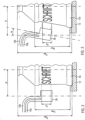
- the print head itself can, as in Figs. 2 and 3 indicated, possibly have two ink supply connections so that you can choose between two printing colors.
- the ink supply connections 13a and 13b are supplied by at least one ink tank 15, which is positioned in particular on the transport carousel 4 so that it rotates. This makes it possible to print the containers with a maximum of two different colors. In particular, only one ink supply with one color can be provided. When printing with only one color, it is preferable to choose a color that contrasts with the container color or, in the case of transparent containers10, the liquid color. This means that the legibility of the marking can be guaranteed even with just one color.
- each print head is also different Figs. 2 and 3 results in adjustable height and distance from the axis of rotation A of each turntable as well as the angle of inclination towards the container.
- a container After a container has been handed over, it can be aligned for the subsequent pressure in a first area I, in particular with the help of sensors (not shown). In the second area II, a pretreatment can then take place with the help of a pretreatment unit 7.
- the actual printing process takes place via the adjoining third area III, which in this exemplary embodiment extends over 240°.
- the printed container can then be finally cured in the subsequent fourth area IV with the aid of an after-treatment unit 20, in particular a UV light-emitting, preferably LED or mercury vapor lamp, which can be provided in addition to or as an alternative to the individual rotating pinning lamps 5a.
- an after-treatment unit 20 in particular a UV light-emitting, preferably LED or mercury vapor lamp, which can be provided in addition to or as an alternative to the individual rotating pinning lamps 5a.
- the marking which was carried out by pressure, can be checked in the fifth area V, in particular with the help of sensors (not shown).
- the unoccupied printing station 5 and the turntable (not shown) can now be cleaned of ink residue and other dirt using the cleaning unit 9.
- the labeling unit is preferably an unit with which wrap-around labels can be applied.
- a cleaning unit 9 for cleaning the printing stations 5 can also be arranged on the periphery of the transport carousel 4.
- a commercially available bottle to be provided with a label stands on the turntable 12 in a printing station 5.
- the bottle for example, has a total height H between 15 and 35cm.
- the maximum printable area H max which in conventional bottles extends from the bottom to the beginning of the tapered shoulder area/bottle neck, is therefore less than the total height and is only about 3/5 to 4/5 of it.
- a partial area H D is printed, which preferably extends over less than half, in particular less than only a third, of the H max .
- this is the area of a brand lettering, for example, incorporated into the bottle in relief, as is common in soft drink bottles, for example.
- the height of the print area of the print head can be adjusted to this range, either by shifting the height of the entire print head or by using only part of the print nozzles of a print head that extends over a greater height.
- the print heads are height-adjustable by means of a motor drive; particularly preferably, all print heads are height-adjusted by means of a common drive.
- the distance R to the axis of rotation A of the turntable is also adjustable.
- a container 110 for printing at a printing station 5 the shape of which differs from that in Fig. 2 differs in that the maximum printable area H max tapers conically from the bottom of the container to the neck. So that such containers can also be printed, the inclination angle ⁇ of the print head 5a according to the invention of the printing station 5 can also be adjusted accordingly.
- the print heads are preferably adjustable in inclination angle by means of a motor drive.
Applications Claiming Priority (1)
| Application Number | Priority Date | Filing Date | Title |
|---|---|---|---|
| DE102022122911.4A DE102022122911A1 (de) | 2022-09-09 | 2022-09-09 | Direktdruckmaschine |
Publications (1)
| Publication Number | Publication Date |
|---|---|
| EP4335647A1 true EP4335647A1 (fr) | 2024-03-13 |
Family
ID=87419108
Family Applications (1)
| Application Number | Title | Priority Date | Filing Date |
|---|---|---|---|
| EP23186064.4A Pending EP4335647A1 (fr) | 2022-09-09 | 2023-07-18 | Machine d'impression directe |
Country Status (4)
| Country | Link |
|---|---|
| US (1) | US20240083178A1 (fr) |
| EP (1) | EP4335647A1 (fr) |
| CN (1) | CN117681580A (fr) |
| DE (1) | DE102022122911A1 (fr) |
Citations (5)
| Publication number | Priority date | Publication date | Assignee | Title |
|---|---|---|---|---|
| EP2960057A1 (fr) * | 2014-06-25 | 2015-12-30 | Sidel S.p.a. Con Socio Unico | Dispositif et procédé pour décorer la surface des récipients de forme irrégulière |
| DE102015215224A1 (de) * | 2015-08-10 | 2017-02-16 | Krones Ag | Behälterbehandlungsmaschine und Verfahren zur Bedruckung von Behältern |
| CN107107628A (zh) * | 2015-03-04 | 2017-08-29 | 柯斯梅私人股份公司 | 贴标机 |
| US20180009246A1 (en) * | 2015-01-12 | 2018-01-11 | Khs Gmbh | Measuring system and method for calibrating printing stations |
| US20190291407A1 (en) * | 2018-02-28 | 2019-09-26 | Jet Printers L.L.C. | Custom printing of cups, glasses, and other vessels |
Family Cites Families (5)
| Publication number | Priority date | Publication date | Assignee | Title |
|---|---|---|---|---|
| DE102009005180A1 (de) | 2009-01-15 | 2010-07-22 | Khs Ag | Behälterbehandlungsmaschine |
| DE102009013477B4 (de) | 2009-03-19 | 2012-01-12 | Khs Gmbh | Druckvorrichtung zum Bedrucken von Flaschen oder dergleichen Behältern |
| DE102009020702B4 (de) | 2009-05-11 | 2011-09-15 | Khs Gmbh | Drucksystem zum Bedrucken von Flaschen oder dergleichen Behältern sowie Druckvorrichtung oder -maschine mit einem solchen Drucksystem |
| DE102009058219A1 (de) | 2009-12-15 | 2011-06-16 | Till, Volker, Dipl.-Ing. | Anlage zum Bedrucken von Behältern |
| DE202013105244U1 (de) | 2013-11-20 | 2015-02-27 | Krones Ag | Direktdruckmaschine zum Bedrucken von Behältern |
-
2022
- 2022-09-09 DE DE102022122911.4A patent/DE102022122911A1/de active Pending
-
2023
- 2023-07-18 EP EP23186064.4A patent/EP4335647A1/fr active Pending
- 2023-09-05 CN CN202311135877.7A patent/CN117681580A/zh active Pending
- 2023-09-08 US US18/463,881 patent/US20240083178A1/en active Pending
Patent Citations (5)
| Publication number | Priority date | Publication date | Assignee | Title |
|---|---|---|---|---|
| EP2960057A1 (fr) * | 2014-06-25 | 2015-12-30 | Sidel S.p.a. Con Socio Unico | Dispositif et procédé pour décorer la surface des récipients de forme irrégulière |
| US20180009246A1 (en) * | 2015-01-12 | 2018-01-11 | Khs Gmbh | Measuring system and method for calibrating printing stations |
| CN107107628A (zh) * | 2015-03-04 | 2017-08-29 | 柯斯梅私人股份公司 | 贴标机 |
| DE102015215224A1 (de) * | 2015-08-10 | 2017-02-16 | Krones Ag | Behälterbehandlungsmaschine und Verfahren zur Bedruckung von Behältern |
| US20190291407A1 (en) * | 2018-02-28 | 2019-09-26 | Jet Printers L.L.C. | Custom printing of cups, glasses, and other vessels |
Also Published As
| Publication number | Publication date |
|---|---|
| CN117681580A (zh) | 2024-03-12 |
| DE102022122911A1 (de) | 2024-03-14 |
| US20240083178A1 (en) | 2024-03-14 |
Similar Documents
| Publication | Publication Date | Title |
|---|---|---|
| EP3337667B1 (fr) | Machine d'impression directe et procédé pour effectuer une impression directe sur des contenants | |
| EP0535512B1 (fr) | Procédé et dispositif pour imprimer des articles au moins partiellement coniques | |
| EP2349850A1 (fr) | Procédé et dispositif pour équiper des récipients | |
| EP3147129B1 (fr) | Procédé et dispositif d'impression de récipients | |
| EP2459385B1 (fr) | Systeme servant a imprimer des contenants | |
| EP2855159B1 (fr) | Procédé et dispositif de contrôle et de correction d'une impression directe sur des contenants à contour superficiel en relief | |
| EP2479036B1 (fr) | Dispositif et procédé destinés à l'impression de récipients | |
| DE19927668B4 (de) | Verfahren und Vorrichtung zum Herstellen eines ausrichtbaren Behälters | |
| DE102013208065A1 (de) | Rundläufermaschine zur Bedruckung von Behältern | |
| DE102009058212B4 (de) | Verfahren zum Betreiben einer Anlage zum Bedrucken von Behältern | |
| DE102011009393A1 (de) | Vorrichtung und Verfahren zum Bedrucken von Behältern | |
| EP1806233A1 (fr) | Dispositif pour imprimer sur bouteilles et récipients similaires | |
| WO1993023180A1 (fr) | Machine d'inspection en continu de recipients | |
| EP3858750B1 (fr) | Dispositif et procédé de marquage des conteneurs | |
| DE102013213843A1 (de) | Behälterbehandlungsvorrichtung zur Bedruckung von Behältern | |
| WO2018108361A1 (fr) | Procédé et machine d'impression directe pour effectuer une impression directe sur des contenants circulaires | |
| DE102010036028A1 (de) | Verfahren zum Herstellen und Behandeln von Behältern | |
| DE102020132131A1 (de) | Behälterbehandlungsmaschine mit Drehkränzen | |
| DE102015211770A1 (de) | Vorrichtung und Verfahren zum Bedrucken von Behälterverschlüssen | |
| EP4335647A1 (fr) | Machine d'impression directe | |
| WO2009115169A1 (fr) | Système de transport de bouteilles, et dispositif de traitement de bouteilles | |
| EP4188714A1 (fr) | Dispositif de gaufrage ou d'étiquetage de récipients | |
| DE202013004057U1 (de) | Behälterausstattungsanlage | |
| DE102019125850A1 (de) | Verfahren und System zur Ausstattung von Behältern und zur Bedruckung von Schraubverschlüssen für die Behälter | |
| DE202013004037U1 (de) | Behälterausstattungsanlage |
Legal Events
| Date | Code | Title | Description |
|---|---|---|---|
| PUAI | Public reference made under article 153(3) epc to a published international application that has entered the european phase |
Free format text: ORIGINAL CODE: 0009012 |
|
| STAA | Information on the status of an ep patent application or granted ep patent |
Free format text: STATUS: THE APPLICATION HAS BEEN PUBLISHED |
|
| AK | Designated contracting states |
Kind code of ref document: A1 Designated state(s): AL AT BE BG CH CY CZ DE DK EE ES FI FR GB GR HR HU IE IS IT LI LT LU LV MC ME MK MT NL NO PL PT RO RS SE SI SK SM TR |