EP4331908B1 - Appui-tête - Google Patents
Appui-tête Download PDFInfo
- Publication number
- EP4331908B1 EP4331908B1 EP23191498.7A EP23191498A EP4331908B1 EP 4331908 B1 EP4331908 B1 EP 4331908B1 EP 23191498 A EP23191498 A EP 23191498A EP 4331908 B1 EP4331908 B1 EP 4331908B1
- Authority
- EP
- European Patent Office
- Prior art keywords
- link
- head part
- headrest
- control arm
- headrest according
- Prior art date
- Legal status (The legal status is an assumption and is not a legal conclusion. Google has not performed a legal analysis and makes no representation as to the accuracy of the status listed.)
- Active
Links
Images







Classifications
-
- B—PERFORMING OPERATIONS; TRANSPORTING
- B60—VEHICLES IN GENERAL
- B60N—SEATS SPECIALLY ADAPTED FOR VEHICLES; VEHICLE PASSENGER ACCOMMODATION NOT OTHERWISE PROVIDED FOR
- B60N2/00—Seats specially adapted for vehicles; Arrangement or mounting of seats in vehicles
- B60N2/02—Seats specially adapted for vehicles; Arrangement or mounting of seats in vehicles the seat or part thereof being movable, e.g. adjustable
- B60N2/0224—Non-manual adjustments, e.g. with electrical operation
- B60N2/02246—Electric motors therefor
- B60N2/02253—Electric motors therefor characterised by the transmission between the electric motor and the seat or seat parts
-
- B—PERFORMING OPERATIONS; TRANSPORTING
- B60—VEHICLES IN GENERAL
- B60N—SEATS SPECIALLY ADAPTED FOR VEHICLES; VEHICLE PASSENGER ACCOMMODATION NOT OTHERWISE PROVIDED FOR
- B60N2/00—Seats specially adapted for vehicles; Arrangement or mounting of seats in vehicles
- B60N2/80—Head-rests
- B60N2/806—Head-rests movable or adjustable
- B60N2/809—Head-rests movable or adjustable vertically slidable
-
- B—PERFORMING OPERATIONS; TRANSPORTING
- B60—VEHICLES IN GENERAL
- B60N—SEATS SPECIALLY ADAPTED FOR VEHICLES; VEHICLE PASSENGER ACCOMMODATION NOT OTHERWISE PROVIDED FOR
- B60N2/00—Seats specially adapted for vehicles; Arrangement or mounting of seats in vehicles
- B60N2/80—Head-rests
- B60N2/806—Head-rests movable or adjustable
- B60N2/865—Head-rests movable or adjustable providing a fore-and-aft movement with respect to the occupant's head
Definitions
- the invention relates to a headrest for a vehicle seat.
- a vehicle within the meaning of the invention can be a land, air or water vehicle.
- a headrest which has a head part and a holding element.
- the headrest is attached to the backrest of a vehicle seat using the holding element.
- a seat occupant can support themselves on the head part.
- the head part can be moved between a first position and a second position by means of a four-bar mechanism which comprises two links arranged one behind the other on each of the two side areas of the headrest.
- the headrest can be moved between the first and second positions using an adjustment device.
- the adjustment device comprises a first guide rail that is firmly connected to a handlebar and a second guide rail that is firmly connected to the head section or the holding element.
- An adjusting element passes through both guide rails.
- the shape of the guide rails is constructed from the relative position of the guide rails in all positions of movement between the first position and the second position.
- the adjusting element is motor-driven, for example, by a spindle drive.
- the DE 10 2010 007 942 A1 describes a headrest with a headrest part which is held to a base of the headrest with a four-bar linkage.
- the four-bar linkage comprises a first pair of links and a second pair of links, each pair of links forming pivot axes with the base and with the headrest part.
- Locking structures are formed on one of the pairs of links, which can be brought into engagement with a latch which is pivotably held on the base in order to lock the headrest part in the set position.
- a headrest which comprises a holding element and a headrest.
- the headrest forms a four-bar linkage with the holding element and with a first link and a second link.
- the headrest has a movable latch with latch structures which can be releasably engaged with latch structures formed on one of the links.
- a headrest from the prior art which comprises a head part, a holding element, a four-bar linkage device and a drive device.
- the headrest should be further developed with regard to the possibilities of its adjustment.
- the headrest comprises a head part and a holding device with at least one holding element.
- the head part forms a support for the occupant's head.
- the holding device is intended for mounting the head part on a vehicle seat.
- the holding device is connected to the vehicle seat in a fixed or adjustable manner. For example, the holding device can be adjusted to different height positions relative to the vehicle seat and, if necessary, fixed in these positions.
- the head part is connected to the holding element so as to be movable relative to the holding device between a first position and a second position on a coupling curve.
- Each steering device forms, for example, at least one swivel joint with the holding device and at least one swivel joint with the head part.
- a drive device of the headrest is designed to adjust and/or lock the position of the head part relative to the holding part between the first position and the second position.
- the drive device comprises a guide, an adjusting element that engages in the guide, and a guide that guides the guide on a movement path between a primary position and a secondary position.
- the guide and the adjusting element are assigned to different components of the four-bar mechanism.
- the adjusting device comprises a guide rail which is movably guided on a first component of the four-bar linkage device on a defined path and an adjusting element which is fixedly arranged on a second component of the four-bar linkage device and which engages in the guide rail.
- One advantage of the movable link is that a link component which the link has has large guide surfaces with which it can be guided on a component of the four-bar linkage.
- the link can be guided on one of the components, the holding device or the head part, and the actuating element is held in a small form on another component of the four-bar linkage.
- the link is assigned to a link component, for example.
- the link is movably guided on one of the components of the four-bar linkage and is formed in a separate component.
- the link is movably guided, for example, on the holding element, on the head part or on one of the steering devices, ie on the first steering device or on the second steering device.
- the actuating element is eg connected to another component of the four-bar mechanism, ie with the Holding element, firmly connected to one of the steering devices or alternatively to the head part. It is important that the guide of the link and the adjusting element are assigned to different components of the four-bar mechanism.
- Component pairings are advantageous in which the path between the actuator and the guide increases or decreases continuously as the head section moves between the first position and the second position. These are, for example, pairings between the head section or holding device and one of the handlebars or pairings between two handlebars.
- the guide rail is movably guided on the head part or on the holding element and the adjusting element is firmly connected to one of the steering devices.
- the guide rail can also be movably guided on one of the steering devices and the adjusting element is firmly arranged on the holding element or on the head part.
- an arrangement of the guide rail and adjusting element with a small distance between them is possible.
- the embodiment offers great flexibility in the design of the headrest.
- Pairings between the headrest and the holding device or between the first handlebar and the second handlebar of different handlebar devices are also possible.
- the slide can be moved along a linear path, for example.
- a linear movement places low demands on the guidance of the slide or the actuator.
- the drive can be operated with a conventional linear drive, which reduces the construction effort.
- the slide can also be moved along a non-linear path. be able to move translationally. This can be, for example, a curved path or a freely formed path.
- a link is understood to be any form of path limitation by which surfaces of a link component in which the link is formed are movably guided. The path limitations only allow movement on a movement path in opposite orientations.
- a longitudinal center axis of the gate is designed according to a path of movement that an actuating element moves through relative to a gate component or a gate structure while the head part moves between the first position and the second position and while the gate component moves between a primary position and a secondary position within the guide.
- the gate component while the head part moves between the first and the second position, for example, the gate component also moves relative to the guide between the primary and the secondary position.
- the path of movement of the actuating element relative to the gate component results in the shape of the gate.
- the links of the four-bar linkage for example, have the same or different lengths. These features can be used to influence the coupling curve of the four-bar linkage and thus the movement of the head section.
- the links of the four-bar linkage are arranged parallel or non-parallel to each other.
- the coupling curve of the four-bar linkage can also be influenced with these features.
- each steering device has at least two steering arms arranged offset transversely to the adjustment direction, with a first steering arm being hinged to a first side region of the head part and a second steering arm being hinged to a second side region of the head part.
- the steering arms arranged offset transversely to the adjustment direction are connected to the head part only by the joints, for example. According to an alternative embodiment, they can have additional connecting struts for stiffening.
- the holding device is, for example, adjustably mounted on the vehicle seat.
- At least two linkages of the four-bar linkage are arranged one behind the other in the direction of adjustment.
- the linkages are aligned approximately vertically in a middle position. If the linkages are arranged approximately vertically in a middle position, a very narrow design of the adjustment device can be achieved - viewed laterally.
- the head part includes, for example, a head support plate and a rear extension.
- the head support plate is mounted so that it can move relative to the extension. This provides an alternative or additional option for vertical adjustment. In the latter case, the adjustment range of the vertical adjustment can be increased.
- the actuating element or the gate is driven, for example, by a drive of the drive device.
- the drive is not important for the invention.
- a suitable drive can be selected.
- the drive includes a motor and a gearbox. Spindle, rack, belt, chain or cable drives can be used.
- a control system which regulates the motor functions, e.g. switches the motor on and off and, if necessary, regulates the direction of rotation of the motor.
- the control can be operated, for example, from a control element that is arranged in the vehicle interior, e.g. on a vehicle seat provided with a headrest.
- a headrest according to a first embodiment is designated in the figures by the reference numeral 10.
- the headrest 10 comprises according to Fig. 1 a head part 11 with a head support surface 12.
- the head support surface 12 forms an abutment for the head of an occupant of a vehicle seat (not shown), to which the headrest 10 can be fastened.
- the headrest 10 further comprises a holding device 33 with at least one holding element 13, which provides means for adjustable or non-adjustable fastening of the headrest 10 to the vehicle seat.
- the holding device 33 or the holding element 13 is vertically adjustable in directions z1 and z2 relative to the vehicle seat - in particular to a backrest of the vehicle seat.
- an adjustment device 20 comprising a four-bar mechanism 14
- the head part 11 can be moved on a coupling curve in the directions x1 and x2 between a first rear position and a second front position.
- the four-bar mechanism 14 comprises a first steering device 15 and a second steering device 16.
- the steering device 15 forms a swivel joint G1 with a swivel axis a1 with the holding device 33 and a swivel joint G2 with a swivel axis a2 with the head part 11.
- the steering device 16 also forms a swivel joint G3 with a swivel axis a3 with the holding device 33 and a swivel joint G4 with a swivel axis a4 with the head part 11.
- the longitudinal axes m1 and m2 of the steering devices 15 and 16 are parallel to one another.
- the longitudinal axes m1 and m2 could also be designed in such a way that a trapezoidal four-bar joint is formed with the holding element 13 and the head part 11, i.e. the longitudinal axes m1 and m2 are not parallel.
- the distance between the joints G1 and G3 would be unequal to the distance between the joints G2 and G4, whereby the distance between the joints G1 and G3 can be greater or smaller than the distance between the joints G2 and G4.
- the steering device 15 has a length L1 between the joints G1 and G2 and the steering device 16 has a length L2 between the joints G3 and G4.
- the lengths L1 and L2 are equal.
- the length L1 can be greater or smaller than the length L2 according to alternative embodiments.
- the steering device 15 may have at least two parallel steering arms 24 transverse to the adjustment direction x1 and x2 (see Fig. 2 ), with a link 24 being hinged to a side region 34a and a link 24 being hinged to a side region 34b of the head part 11.
- the The steering device 16 has one or at least two parallel steering devices 24 transverse to the adjustment direction, so that adjustment devices 20 are present. All steering devices 24 of the steering device 15 form, for example, swivel joints G1 with the holding device 33 and swivel joints G2 with the head part 11. Accordingly, all steering devices 24 of the steering device 16 form swivel joints G3 with the holding device 33 and swivel joints G4 with the head part 11.
- the parallel steering devices 24 of the steering devices 15 and 16 are spaced apart from one another, for example with respect to the y-direction.
- the head part 11 comprises a rear extension 22, which forms the pivot joints G2 and G4 with the steering devices 15 and 16.
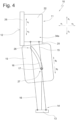
- the head part 11 is thus on a coupling curve between the first rear position (see Fig. 1 ) and the second front position (see Fig. 4 )
- the parts comprised by the four-bar mechanism 14, namely head part 11, holding device 33, steering device 15 and steering device 16, have a defined relative position to one another in every position of the head part 11.
- Each of the defined relative positions of the four-bar mechanism 14 can be adjusted using a drive device 30. While the adjustment device 20 is designed as described above in all of the described embodiments, different variants of the drive devices 30, 30', 30" and 30′′′ that are essential to the invention are described below.
- the drive device 30 comprises a guide 18 with a longitudinal axis m3, on one of the elements of the four-bar mechanism 14 and an actuating element 17, which engages in the guide 18 in such a way that it can be guided by the guide 18.
- the actuating element 17 is assigned to another of the elements of the four-bar mechanism 14.
- each adjusting device 20 is assigned an adjusting element 17 and a guide component 19.
- the adjusting element 17 is firmly connected to the holding element 13.
- a drive 23 is provided for moving a guide component 19 on which the guide 18 is formed, which is explained further below.
- the link component 19 can be guided on any path.
- the link component 19 in the first embodiment is guided on a linear path by means of the guide 21 and moves between a primary position and a secondary position along a longitudinal axis that is parallel to the longitudinal axis m1.
- the actuating element 17 engages in the link 18 and is immovably connected to the holding element 13.
- the guide 21 is only in Fig. 1 recognizable and indicated schematically with broken lines.
- the actuating element 17 moves from a first end region 26 to a second end region 27 of the gate 18 during the movement of the gate component 19 from the primary position to the secondary position relative to the gate 18.
- the movement of the actuating element 17 between the primary position and the secondary position occurs in order to move the head part 11 from the first position to the second position.
- the link 18 is formed in a separate link component 19, which is attached to the handlebar device 15 is movably guided.
- the adjusting element 17 is located at the end region 26 of the guide 18 in the primary position, with the head part 11 in the first position.
- the link component 19 was moved in the direction q1 such that the adjusting element 17 is arranged in a central area of the link 18.
- the head part 11 was adjusted to a middle position between the first position and the second position.
- a movement of the link component 19 in the direction q1 to a secondary position such that the adjusting element 17 is arranged in the end region 27 of the guide 18, results in a movement of the head part 11 into the second position.
- the head part 11 moves between the first position and the second position, the head part 11 is moved in the direction x1 and also slightly adjusted in the direction z1 and z2.
- the reason for this is the pivoting movement of the steering device 15 about the pivot axis a1 and the pivoting movement of the steering device 16 about the pivot axis a3.
- the joint G2 therefore performs a circular movement about the pivot axis a1 and the joint G4 performs a circular movement about the pivot axis a3.
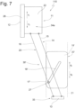
- a second embodiment of the headrest 110 is shown in the Fig. 5 to 7
- the adjusting device 20 is designed as in the first example.
- the second Embodiment differs with regard to the drive device.
- a drive device 30' of the second embodiment see Fig. 5
- the actuating element 17' is immovably connected to the steering device 16 and the guide 18' is movably guided on the holding element 13 by means of a guide 21 *.
- the guide 18' is formed here on a guide component 19'.
- the guide 18 can be moved along a movement path that is defined by the guide 21'.
- the movement path can be a translational, a rotational or a mixed movement with translational and rotational components.
- the guide 21' guides the guide 18' along a linear movement path. This enables the movement of the guide 18' by means of a linear drive.
- the adjusting element 17' fixedly arranged on the steering device 16 engages in the guide 18', which is assigned to the guide component 19', which is guided by the guide 21' on the holding element 13.
- the head part 11 is in the first position.
- the adjusting element 17' is arranged at the end region 26 of the guide 18'. If the guide component 19' is moved in the direction q1, the head part 11 is displaced in the direction x1.
- the head part 11 is in a middle position between the first position and the second Position shifted.
- the adjusting element 17' is positioned approximately in the middle of the gate 18'. A further movement of the gate component 19' in the direction q1 results in the head part 11 shifting in the direction x1 to the second position (see Fig. 7 ).
- the adjusting element 17' is then located at the end region 27 of the guide 18'.
- the head part moves from the second position to the first position.
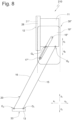
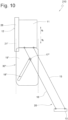
- a third embodiment of the headrest 210 is shown in the Fig. 8 to 10 While the adjusting device 20 is designed according to the first and second embodiments, there are differences with regard to the drive device 30".
- the adjusting element 17" is fixed, ie immovable relative to the steering device 16, on the steering device 16.
- a link component 19" with a link 18" is guided on the head part 12 so as to be movable relative to the head part 11 by means of a guide 21".
- the link component 19" moves in the direction q2
- the head part 11 is moved from the first position according to Fig. 8 about the position according to Fig. 9 in the second position according to Fig. 10
- the drive device 30" can, for example, have a drive 23 which corresponds to the first and second embodiments.
- the adjusting element 17 could also be held on the head part 11 and be immovable relative to it.
- the link component 19 could be movably guided on the handlebar 16 and the adjusting element 17 is firmly connected to the holding element 13 or to the head part 11.
- the link component 19' is movably attached to the holding element 13 and the actuating element 17' is fixedly attached to the steering device 15.
- the link component 19' is movable on the head part 11 and the actuating element 17' is fixedly arranged on one of the links 15.
- the link component 19' is movable on the head part 11 and the actuating element 17' is fixedly arranged on one of the links 15.
- the movable link component 19' can basically be connected to the holding element 13 or the head part 11 and the adjusting element 17' can be firmly connected to one of the steering devices 15 or 16.
- the movable link component 19' can also be movably guided on one of the steering devices 15 or 16 and the actuating element 17' can be firmly connected to one of the components holding device 33 or head part 11.
- the adjusting element 17′′′ is held firmly on a first link and the link component 19" ⁇ is movably guided on a second link.
- the adjusting element 17′′′ is on the link 15 and the Link component 19′′′ is movably guided on the handlebar 16.
- the link component could also be movably mounted on the handlebar 15 and the actuating element could be held immovably relative to the handlebar 16 on the handlebar 16.
- the holding element 13′′′ is formed by an inclined plane, wherein in a first end position the adjusting device 20′′′ is positioned such that the center axes m1 and m2 of the links 15 and 16 are at right angles to the inclined plane.
- a height adjustment of the head part 11 in the directions z1 and z2 can take place independently of the design of the drive device 30, 30' and 30" and the position of the adjustment device 20, in that the holding element 13 is adjustable in the directions z1 and z2.
- the holding element 13 can be provided with support rods which can be fastened in guide sleeves fixed to the backrest in different height positions, e.g. by means of a locking device in a known manner.
- a head support plate 28 can be guided on the extension 22 so as to be adjustable relative to the extension 22 in the directions v1 and v2.
- the head support plate 28 can have guide elements (not shown) which interact with guide elements on the extension 22.
- the head support plate 28 can be fixed in the respective relative position to the extension 22, for example in several stages or continuously.
- the drive device 30 comprises, for example, a drive 23 with a motor 25 and a gear 29 to move the link component 19'.
- the drive 23 is not essential to the invention, i.e. suitable elements can be selected.
- a spindle drive is suitable as a gear 29, whereby the motor 25 drives a spindle 31 or a spindle nut 32, to which the link component 19' is connected.
- the spindle 31 provided with a thread is rotatably driven by the motor 25 so that the spindle nut 32, whose thread is in engagement with the thread of the spindle nut 32, moves parallel to the longitudinal axis m2.
- the spindle nut 32 is connected to the link component 19, 19' or 19" in such a way that the link component moves in the desired direction depending on the direction of rotation of the spindle 31.
- a spindle drive for example, has the advantage that the self-locking mechanism fixes the head part 11 in the set position. In other words, no separate locking device is necessary to fix the head part in the set position.
- a linear drive can be used, for example, which is mounted so as to be movable that a drive part can follow the link component 19.
- a first movably guided gate 18' interacts with an adjusting element 17' which is fixedly attached to the first link device 15 is arranged and a second guide rail 18' guided and moved parallel to the first guide rail 18' cooperates with an actuating element 17' which is firmly connected to the second link device 16 or to a link arranged offset transversely to the direction of movement to the link 15 or 16.
Landscapes
- Engineering & Computer Science (AREA)
- Aviation & Aerospace Engineering (AREA)
- Transportation (AREA)
- Mechanical Engineering (AREA)
- Chair Legs, Seat Parts, And Backrests (AREA)
Claims (15)
- Appuie-tête avec une partie de tête (11) et avec un dispositif de maintien (33) comprenant au moins un élément de maintien (13) pour monter de façon inamovible ou réglable la partie de tête (11) sur un siège de véhicule, avec un dispositif de réglage (20) comprenant un dispositif de quadrilatère articulé (14) doté d'au moins un premier dispositif d'articulation (15) et d'un deuxième dispositif d'articulation (16), avec lequel la partie de tête (11) est reliée de façon mobile à l'élément de maintien (13) entre une première position et une deuxième position par rapport à l'élément de maintien (13), et avec un dispositif d'entraînement (30, 30') avec lequel la position de la partie de tête (11) par rapport à l'élément de maintien (13) peut être modifiée et/ou fixée entre la première position et la deuxième position, caractérisé en ce que le dispositif d'entraînement (30, 30') comprend une coulisse (18, 18') qui est guidée en déplacement sur une trajectoire définie sur une première pièce du dispositif de quadrilatère articulé (14) au moyen d'un guide (21, 21') et qu'un élément de réglage (17, 17') qui pénètre dans la coulisse (18, 18') est disposé sur une deuxième pièce du dispositif de quadrilatère articulé (14).
- Appuie-tête selon une des revendications précédentes, caractérisé en ce que la coulisse (18, 18') est guidée en déplacement sur l'élément de maintien (13) ou sur la partie de tête (11) et que l'élément de réglage (17, 17') est relié de façon fixe avec un des dispositifs d'articulation (15, 16) ou que la coulisse (18, 18') est guidée en déplacement sur un des dispositifs d'articulation (15, 16) et que l'élément de réglage (17, 17') est relié de façon fixe avec l'élément de maintien (13) ou avec la partie de tête (11).
- Appuie-tête selon une des revendications précédentes, caractérisé en ce que la coulisse (18, 18') est guidée en déplacement sur un premier des dispositifs d'articulation (15, 16) et que l'élément de réglage (17, 17') est relié de façon fixe avec un deuxième des dispositifs d'articulation (15, 16).
- Appuie-tête caractérisé en ce que chaque dispositif d'articulation (15, 16) forme au moins une articulation pivotante (G1, G3) avec l'élément de maintien (13) et au moins une articulation pivotante (G2, G4) avec la partie de tête (11).
- Appuie-tête selon une des revendications précédentes, caractérisé en ce que la coulisse (18, 18') peut se déplacer de façon linéaire au moyen du guide (21, 21').
- Appuie-tête selon une des revendications précédentes, caractérisé en ce que le guide (21, 21') est configuré sous la forme d'au moins une deuxième coulisse pour une pièce de coulisse (19, 19', 19") de la coulisse (18, 18'), l'élément de réglage (17, 17') étant guidé dans les deux coulisses.
- Appuie-tête selon une des revendications précédentes, caractérisé en ce qu'un axe central longitudinal (m3) de la coulisse (18, 18') est construit selon une trajectoire de déplacement qui traverse un élément de réglage (17, 17') par rapport à une pièce de coulisse (19, 19') ou à une structure de coulisse, tandis que la partie de tête (11) se déplace entre la première position et la deuxième position et tandis que, simultanément, l'élément de réglage (17, 17') ou la pièce de coulisse (19') se déplace entre une position primaire et une position secondaire à l'intérieur du guide (21, 21').
- Appuie-tête selon une des revendications précédentes, caractérisé en ce que les dispositifs d'articulation (15, 16) du dispositif de quadrilatère articulé (14) présentent des longueurs différentes (L1, L2).
- Appuie-tête selon une des revendications précédentes, caractérisé en ce que des axes centraux longitudinaux (m1, m2) des dispositifs d'articulation (15, 16) du dispositif de quadrilatère articulé (14) sont disposés parallèlement ou non parallèlement entre eux.
- Appuie-tête selon une des revendications précédentes, caractérisé en ce que chaque dispositif d'articulation (15, 16) comporte au moins deux articulations (24a, 24b) disposées transversalement à une direction de réglage (x1, x2), une première articulation (24) étant articulée à une première zone latérale (34a) de la partie de tête (11) et une deuxième articulation (24) à une deuxième zone latérale (34b) de la partie de tête (11).
- Appuie-tête selon une des revendications précédentes, caractérisé en ce que le dispositif de maintien (33) peut être monté de façon réglable sur un siège de véhicule.
- Appuie-tête selon une des revendications précédentes, caractérisé en ce qu'au moins deux articulations (G1, G2, G3, G4) du dispositif de quadrilatère articulé (14) sont disposés l'un derrière l'autre dans la direction de réglage.
- Appuie-tête selon une des revendications précédentes, caractérisé en ce qu'une plaque repose-tête (28) est montée sur un prolongement (22) de la partie de tête (11) de façon mobile par rapport à ce prolongement (22).
- Appuie-tête selon une des revendications précédentes, caractérisé en ce que l'élément de réglage (17, 17') ou la coulisse (18, 18') est entraîné par un dispositif d'entraînement (23) qui comprend un moteur (25) et une transmission (29).
- Appuie-tête selon une des revendications précédentes, caractérisé en ce que le dispositif d'entraînement (30, 30') peut être commandé avec un dispositif de commande.
Applications Claiming Priority (1)
| Application Number | Priority Date | Filing Date | Title |
|---|---|---|---|
| DE102022122310.8A DE102022122310A1 (de) | 2022-09-02 | 2022-09-02 | Kopfstütze |
Publications (2)
| Publication Number | Publication Date |
|---|---|
| EP4331908A1 EP4331908A1 (fr) | 2024-03-06 |
| EP4331908B1 true EP4331908B1 (fr) | 2024-12-04 |
Family
ID=87575839
Family Applications (1)
| Application Number | Title | Priority Date | Filing Date |
|---|---|---|---|
| EP23191498.7A Active EP4331908B1 (fr) | 2022-09-02 | 2023-08-15 | Appui-tête |
Country Status (2)
| Country | Link |
|---|---|
| EP (1) | EP4331908B1 (fr) |
| DE (1) | DE102022122310A1 (fr) |
Family Cites Families (6)
| Publication number | Priority date | Publication date | Assignee | Title |
|---|---|---|---|---|
| DE102010007942B4 (de) | 2010-02-12 | 2012-08-09 | Grammer Aktiengesellschaft | Kopfstütze für Fahrzeugsitze |
| KR101553527B1 (ko) * | 2014-03-17 | 2015-09-17 | 현대다이모스(주) | 전동식 헤드레스트 |
| DE102018109611B4 (de) | 2018-04-10 | 2022-04-21 | Grammer Aktiengesellschaft | Kopfstütze |
| DE102018005316A1 (de) | 2018-07-05 | 2020-01-09 | Grammer Aktiengesellschaft | Kopfstütze |
| CN112977216A (zh) * | 2021-03-26 | 2021-06-18 | 重庆宏立至信科技发展集团有限公司 | 电动平移头枕 |
| CN114801933B (zh) * | 2021-08-26 | 2023-04-07 | 延锋国际座椅系统有限公司 | 一种座椅电动头枕 |
-
2022
- 2022-09-02 DE DE102022122310.8A patent/DE102022122310A1/de active Pending
-
2023
- 2023-08-15 EP EP23191498.7A patent/EP4331908B1/fr active Active
Also Published As
| Publication number | Publication date |
|---|---|
| DE102022122310A1 (de) | 2024-03-07 |
| EP4331908A1 (fr) | 2024-03-06 |
Similar Documents
| Publication | Publication Date | Title |
|---|---|---|
| EP3597488B1 (fr) | Véhicule automobile avec système de blocage et de contact permettant de raccorder électriquement un réseau de bord d'un véhicule automobile à un siège de véhicule amovible ou une installation de siège | |
| DE3902979C2 (de) | Falzmaschine zum Falzen von Dachblechen | |
| EP1243461B1 (fr) | Chassis d'assise de siège pour un siège de véhicule | |
| DE2846632A1 (de) | Hoehenverstellvorrichtung fuer sitze, insbesondere kraftfahrzeugsitze | |
| DE102015013362B4 (de) | Kopfstütze für einen Fahrzeugsitz | |
| DE2844647C2 (de) | Längsverstellvorrichtung für einen Fahrzeugsitz, insbesondere einen Kraftfahrzeugsitz | |
| EP1432885A1 (fr) | Dispositif pour regler la position d'une vitre de vehicule automobile deplacee par un leve-vitre a cable double brin | |
| EP1360085B1 (fr) | Siège, en particulier siège de véhicule, de préférence siège passager d'avion | |
| EP0396153A2 (fr) | Dispositif de réglage en hauteur pour sièges de véhicules | |
| DE4305909C2 (de) | Verstellbare Kraftfahrzeug-Kopfstütze | |
| DE69127909T2 (de) | Schiebe-Hebe-Dach-Vorrichtung für Kraftfahrzeug | |
| DE102018109611B4 (de) | Kopfstütze | |
| EP1064163A1 (fr) | Dispositif deflecteur | |
| EP0918658A1 (fr) | Dossier de siege de vehicule automobile a systeme de reglage pour le pivotement de la tete du dossier | |
| DE3336349A1 (de) | Rueckenlehne mit regelbarer rueckenunterstuetzung | |
| DE4437539C2 (de) | Fahrzeugsitz | |
| DE19838281C1 (de) | Höhenverstellbare Armlehne für ein Kraftfahrzeug | |
| DE19735492A1 (de) | Koaxialtrieb für den Objekttisch eines Mikroskops | |
| DE4302329B4 (de) | Höhenverstelleinrichtung für Sitze, insbesondere Kraftfahrzeugsitze | |
| DE19521883C2 (de) | Fahrzeugsitz | |
| EP4331908A1 (fr) | Appui-tête | |
| EP3970872B1 (fr) | Machine à plier la tôle pourvue de système de butée | |
| EP1961607B1 (fr) | Siège destiné à être installé dans une cabine de conduite | |
| DE3207177C2 (de) | Tisch mit einer in der Höhe und in der Neigung verstellbaren Tischplatte | |
| EP1514725B1 (fr) | Mécanisme de réglage pour un siège arrière de véhicule |
Legal Events
| Date | Code | Title | Description |
|---|---|---|---|
| PUAI | Public reference made under article 153(3) epc to a published international application that has entered the european phase |
Free format text: ORIGINAL CODE: 0009012 |
|
| STAA | Information on the status of an ep patent application or granted ep patent |
Free format text: STATUS: THE APPLICATION HAS BEEN PUBLISHED |
|
| STAA | Information on the status of an ep patent application or granted ep patent |
Free format text: STATUS: REQUEST FOR EXAMINATION WAS MADE |
|
| AK | Designated contracting states |
Kind code of ref document: A1 Designated state(s): AL AT BE BG CH CY CZ DE DK EE ES FI FR GB GR HR HU IE IS IT LI LT LU LV MC ME MK MT NL NO PL PT RO RS SE SI SK SM TR |
|
| 17P | Request for examination filed |
Effective date: 20240216 |
|
| RBV | Designated contracting states (corrected) |
Designated state(s): AL AT BE BG CH CY CZ DE DK EE ES FI FR GB GR HR HU IE IS IT LI LT LU LV MC ME MK MT NL NO PL PT RO RS SE SI SK SM TR |
|
| GRAP | Despatch of communication of intention to grant a patent |
Free format text: ORIGINAL CODE: EPIDOSNIGR1 |
|
| STAA | Information on the status of an ep patent application or granted ep patent |
Free format text: STATUS: GRANT OF PATENT IS INTENDED |
|
| RIC1 | Information provided on ipc code assigned before grant |
Ipc: B60N 2/865 20180101ALI20240628BHEP Ipc: B60N 2/809 20180101ALI20240628BHEP Ipc: B60N 2/02 20060101AFI20240628BHEP |
|
| INTG | Intention to grant announced |
Effective date: 20240801 |
|
| P01 | Opt-out of the competence of the unified patent court (upc) registered |
Free format text: CASE NUMBER: APP_50424/2024 Effective date: 20240905 |
|
| GRAS | Grant fee paid |
Free format text: ORIGINAL CODE: EPIDOSNIGR3 |
|
| GRAA | (expected) grant |
Free format text: ORIGINAL CODE: 0009210 |
|
| STAA | Information on the status of an ep patent application or granted ep patent |
Free format text: STATUS: THE PATENT HAS BEEN GRANTED |
|
| AK | Designated contracting states |
Kind code of ref document: B1 Designated state(s): AL AT BE BG CH CY CZ DE DK EE ES FI FR GB GR HR HU IE IS IT LI LT LU LV MC ME MK MT NL NO PL PT RO RS SE SI SK SM TR |
|
| REG | Reference to a national code |
Ref country code: CH Ref legal event code: EP |
|
| REG | Reference to a national code |
Ref country code: DE Ref legal event code: R096 Ref document number: 502023000361 Country of ref document: DE |
|
| REG | Reference to a national code |
Ref country code: IE Ref legal event code: FG4D Free format text: LANGUAGE OF EP DOCUMENT: GERMAN |
|
| REG | Reference to a national code |
Ref country code: LT Ref legal event code: MG9D |
|
| REG | Reference to a national code |
Ref country code: NL Ref legal event code: MP Effective date: 20241204 |
|
| PG25 | Lapsed in a contracting state [announced via postgrant information from national office to epo] |
Ref country code: HR Free format text: LAPSE BECAUSE OF FAILURE TO SUBMIT A TRANSLATION OF THE DESCRIPTION OR TO PAY THE FEE WITHIN THE PRESCRIBED TIME-LIMIT Effective date: 20241204 |
|
| PG25 | Lapsed in a contracting state [announced via postgrant information from national office to epo] |
Ref country code: FI Free format text: LAPSE BECAUSE OF FAILURE TO SUBMIT A TRANSLATION OF THE DESCRIPTION OR TO PAY THE FEE WITHIN THE PRESCRIBED TIME-LIMIT Effective date: 20241204 |
|
| PG25 | Lapsed in a contracting state [announced via postgrant information from national office to epo] |
Ref country code: BG Free format text: LAPSE BECAUSE OF FAILURE TO SUBMIT A TRANSLATION OF THE DESCRIPTION OR TO PAY THE FEE WITHIN THE PRESCRIBED TIME-LIMIT Effective date: 20241204 |
|
| PG25 | Lapsed in a contracting state [announced via postgrant information from national office to epo] |
Ref country code: ES Free format text: LAPSE BECAUSE OF FAILURE TO SUBMIT A TRANSLATION OF THE DESCRIPTION OR TO PAY THE FEE WITHIN THE PRESCRIBED TIME-LIMIT Effective date: 20241204 |
|
| PG25 | Lapsed in a contracting state [announced via postgrant information from national office to epo] |
Ref country code: NO Free format text: LAPSE BECAUSE OF FAILURE TO SUBMIT A TRANSLATION OF THE DESCRIPTION OR TO PAY THE FEE WITHIN THE PRESCRIBED TIME-LIMIT Effective date: 20250304 |
|
| PG25 | Lapsed in a contracting state [announced via postgrant information from national office to epo] |
Ref country code: GR Free format text: LAPSE BECAUSE OF FAILURE TO SUBMIT A TRANSLATION OF THE DESCRIPTION OR TO PAY THE FEE WITHIN THE PRESCRIBED TIME-LIMIT Effective date: 20250305 Ref country code: LV Free format text: LAPSE BECAUSE OF FAILURE TO SUBMIT A TRANSLATION OF THE DESCRIPTION OR TO PAY THE FEE WITHIN THE PRESCRIBED TIME-LIMIT Effective date: 20241204 |
|
| PG25 | Lapsed in a contracting state [announced via postgrant information from national office to epo] |
Ref country code: RS Free format text: LAPSE BECAUSE OF FAILURE TO SUBMIT A TRANSLATION OF THE DESCRIPTION OR TO PAY THE FEE WITHIN THE PRESCRIBED TIME-LIMIT Effective date: 20250304 |
|
| PG25 | Lapsed in a contracting state [announced via postgrant information from national office to epo] |
Ref country code: NL Free format text: LAPSE BECAUSE OF FAILURE TO SUBMIT A TRANSLATION OF THE DESCRIPTION OR TO PAY THE FEE WITHIN THE PRESCRIBED TIME-LIMIT Effective date: 20241204 |
|
| PG25 | Lapsed in a contracting state [announced via postgrant information from national office to epo] |
Ref country code: SM Free format text: LAPSE BECAUSE OF FAILURE TO SUBMIT A TRANSLATION OF THE DESCRIPTION OR TO PAY THE FEE WITHIN THE PRESCRIBED TIME-LIMIT Effective date: 20241204 |
|
| PG25 | Lapsed in a contracting state [announced via postgrant information from national office to epo] |
Ref country code: PL Free format text: LAPSE BECAUSE OF FAILURE TO SUBMIT A TRANSLATION OF THE DESCRIPTION OR TO PAY THE FEE WITHIN THE PRESCRIBED TIME-LIMIT Effective date: 20241204 |
|
| PG25 | Lapsed in a contracting state [announced via postgrant information from national office to epo] |
Ref country code: IS Free format text: LAPSE BECAUSE OF FAILURE TO SUBMIT A TRANSLATION OF THE DESCRIPTION OR TO PAY THE FEE WITHIN THE PRESCRIBED TIME-LIMIT Effective date: 20250404 |
|
| PG25 | Lapsed in a contracting state [announced via postgrant information from national office to epo] |
Ref country code: PT Free format text: LAPSE BECAUSE OF FAILURE TO SUBMIT A TRANSLATION OF THE DESCRIPTION OR TO PAY THE FEE WITHIN THE PRESCRIBED TIME-LIMIT Effective date: 20250404 |
|
| PG25 | Lapsed in a contracting state [announced via postgrant information from national office to epo] |
Ref country code: EE Free format text: LAPSE BECAUSE OF FAILURE TO SUBMIT A TRANSLATION OF THE DESCRIPTION OR TO PAY THE FEE WITHIN THE PRESCRIBED TIME-LIMIT Effective date: 20241204 |
|
| PG25 | Lapsed in a contracting state [announced via postgrant information from national office to epo] |
Ref country code: RO Free format text: LAPSE BECAUSE OF FAILURE TO SUBMIT A TRANSLATION OF THE DESCRIPTION OR TO PAY THE FEE WITHIN THE PRESCRIBED TIME-LIMIT Effective date: 20241204 |
|
| PG25 | Lapsed in a contracting state [announced via postgrant information from national office to epo] |
Ref country code: SK Free format text: LAPSE BECAUSE OF FAILURE TO SUBMIT A TRANSLATION OF THE DESCRIPTION OR TO PAY THE FEE WITHIN THE PRESCRIBED TIME-LIMIT Effective date: 20241204 |
|
| PG25 | Lapsed in a contracting state [announced via postgrant information from national office to epo] |
Ref country code: CZ Free format text: LAPSE BECAUSE OF FAILURE TO SUBMIT A TRANSLATION OF THE DESCRIPTION OR TO PAY THE FEE WITHIN THE PRESCRIBED TIME-LIMIT Effective date: 20241204 |
|
| PG25 | Lapsed in a contracting state [announced via postgrant information from national office to epo] |
Ref country code: IT Free format text: LAPSE BECAUSE OF FAILURE TO SUBMIT A TRANSLATION OF THE DESCRIPTION OR TO PAY THE FEE WITHIN THE PRESCRIBED TIME-LIMIT Effective date: 20241204 |
|
| REG | Reference to a national code |
Ref country code: DE Ref legal event code: R097 Ref document number: 502023000361 Country of ref document: DE |
|
| PG25 | Lapsed in a contracting state [announced via postgrant information from national office to epo] |
Ref country code: SE Free format text: LAPSE BECAUSE OF FAILURE TO SUBMIT A TRANSLATION OF THE DESCRIPTION OR TO PAY THE FEE WITHIN THE PRESCRIBED TIME-LIMIT Effective date: 20241204 |
|
| PG25 | Lapsed in a contracting state [announced via postgrant information from national office to epo] |
Ref country code: DK Free format text: LAPSE BECAUSE OF FAILURE TO SUBMIT A TRANSLATION OF THE DESCRIPTION OR TO PAY THE FEE WITHIN THE PRESCRIBED TIME-LIMIT Effective date: 20241204 |
|
| PGFP | Annual fee paid to national office [announced via postgrant information from national office to epo] |
Ref country code: DE Payment date: 20250819 Year of fee payment: 3 |
|
| PLBE | No opposition filed within time limit |
Free format text: ORIGINAL CODE: 0009261 |
|
| STAA | Information on the status of an ep patent application or granted ep patent |
Free format text: STATUS: NO OPPOSITION FILED WITHIN TIME LIMIT |
|
| PGFP | Annual fee paid to national office [announced via postgrant information from national office to epo] |
Ref country code: FR Payment date: 20250821 Year of fee payment: 3 Ref country code: AT Payment date: 20251020 Year of fee payment: 3 |
|
| 26N | No opposition filed |
Effective date: 20250905 |
|
| PG25 | Lapsed in a contracting state [announced via postgrant information from national office to epo] |
Ref country code: MC Free format text: LAPSE BECAUSE OF FAILURE TO SUBMIT A TRANSLATION OF THE DESCRIPTION OR TO PAY THE FEE WITHIN THE PRESCRIBED TIME-LIMIT Effective date: 20241204 |
|
| PG25 | Lapsed in a contracting state [announced via postgrant information from national office to epo] |
Ref country code: LU Free format text: LAPSE BECAUSE OF NON-PAYMENT OF DUE FEES Effective date: 20250815 |