EP4331828B1 - Kanalballenpresse mit kreuzabbindung - Google Patents
Kanalballenpresse mit kreuzabbindung Download PDFInfo
- Publication number
- EP4331828B1 EP4331828B1 EP23165735.4A EP23165735A EP4331828B1 EP 4331828 B1 EP4331828 B1 EP 4331828B1 EP 23165735 A EP23165735 A EP 23165735A EP 4331828 B1 EP4331828 B1 EP 4331828B1
- Authority
- EP
- European Patent Office
- Prior art keywords
- channel
- baling press
- strapping
- bale
- press according
- Prior art date
- Legal status (The legal status is an assumption and is not a legal conclusion. Google has not performed a legal analysis and makes no representation as to the accuracy of the status listed.)
- Active
Links
Images






Classifications
-
- B—PERFORMING OPERATIONS; TRANSPORTING
- B65—CONVEYING; PACKING; STORING; HANDLING THIN OR FILAMENTARY MATERIAL
- B65B—MACHINES, APPARATUS OR DEVICES FOR, OR METHODS OF, PACKAGING ARTICLES OR MATERIALS; UNPACKING
- B65B27/00—Bundling particular articles presenting special problems using string, wire, or narrow tape or band; Baling fibrous material, e.g. peat, not otherwise provided for
- B65B27/12—Baling or bundling compressible fibrous material, e.g. peat
-
- B—PERFORMING OPERATIONS; TRANSPORTING
- B30—PRESSES
- B30B—PRESSES IN GENERAL
- B30B15/00—Details of, or accessories for, presses; Auxiliary measures in connection with pressing
-
- B—PERFORMING OPERATIONS; TRANSPORTING
- B30—PRESSES
- B30B—PRESSES IN GENERAL
- B30B9/00—Presses specially adapted for particular purposes
- B30B9/30—Presses specially adapted for particular purposes for baling; Compression boxes therefor
-
- B—PERFORMING OPERATIONS; TRANSPORTING
- B30—PRESSES
- B30B—PRESSES IN GENERAL
- B30B9/00—Presses specially adapted for particular purposes
- B30B9/30—Presses specially adapted for particular purposes for baling; Compression boxes therefor
- B30B9/3003—Details
- B30B9/3014—Ejection means
-
- B—PERFORMING OPERATIONS; TRANSPORTING
- B65—CONVEYING; PACKING; STORING; HANDLING THIN OR FILAMENTARY MATERIAL
- B65B—MACHINES, APPARATUS OR DEVICES FOR, OR METHODS OF, PACKAGING ARTICLES OR MATERIALS; UNPACKING
- B65B13/00—Bundling articles
- B65B13/02—Applying and securing binding material around articles or groups of articles, e.g. using strings, wires, strips, bands or tapes
-
- B—PERFORMING OPERATIONS; TRANSPORTING
- B65—CONVEYING; PACKING; STORING; HANDLING THIN OR FILAMENTARY MATERIAL
- B65B—MACHINES, APPARATUS OR DEVICES FOR, OR METHODS OF, PACKAGING ARTICLES OR MATERIALS; UNPACKING
- B65B13/00—Bundling articles
- B65B13/02—Applying and securing binding material around articles or groups of articles, e.g. using strings, wires, strips, bands or tapes
- B65B13/04—Applying and securing binding material around articles or groups of articles, e.g. using strings, wires, strips, bands or tapes with means for guiding the binding material around the articles prior to severing from supply
-
- B—PERFORMING OPERATIONS; TRANSPORTING
- B65—CONVEYING; PACKING; STORING; HANDLING THIN OR FILAMENTARY MATERIAL
- B65B—MACHINES, APPARATUS OR DEVICES FOR, OR METHODS OF, PACKAGING ARTICLES OR MATERIALS; UNPACKING
- B65B13/00—Bundling articles
- B65B13/18—Details of, or auxiliary devices used in, bundling machines or bundling tools
- B65B13/20—Means for compressing or compacting bundles prior to bundling
-
- B—PERFORMING OPERATIONS; TRANSPORTING
- B65—CONVEYING; PACKING; STORING; HANDLING THIN OR FILAMENTARY MATERIAL
- B65B—MACHINES, APPARATUS OR DEVICES FOR, OR METHODS OF, PACKAGING ARTICLES OR MATERIALS; UNPACKING
- B65B13/00—Bundling articles
- B65B13/18—Details of, or auxiliary devices used in, bundling machines or bundling tools
- B65B13/24—Securing ends of binding material
- B65B13/28—Securing ends of binding material by twisting
-
- B—PERFORMING OPERATIONS; TRANSPORTING
- B65—CONVEYING; PACKING; STORING; HANDLING THIN OR FILAMENTARY MATERIAL
- B65B—MACHINES, APPARATUS OR DEVICES FOR, OR METHODS OF, PACKAGING ARTICLES OR MATERIALS; UNPACKING
- B65B57/00—Automatic control, checking, warning, or safety devices
- B65B57/10—Automatic control, checking, warning, or safety devices responsive to absence, presence, abnormal feed, or misplacement of articles or materials to be packaged
- B65B57/12—Automatic control, checking, warning, or safety devices responsive to absence, presence, abnormal feed, or misplacement of articles or materials to be packaged and operating to control, or stop, the feed of wrapping materials, containers, or packages
-
- B—PERFORMING OPERATIONS; TRANSPORTING
- B65—CONVEYING; PACKING; STORING; HANDLING THIN OR FILAMENTARY MATERIAL
- B65B—MACHINES, APPARATUS OR DEVICES FOR, OR METHODS OF, PACKAGING ARTICLES OR MATERIALS; UNPACKING
- B65B59/00—Arrangements to enable machines to handle articles of different sizes, to produce packages of different sizes, to vary the contents of packages, to handle different types of packaging material, or to give access for cleaning or maintenance purposes
- B65B59/001—Arrangements to enable adjustments related to the product to be packaged
-
- B—PERFORMING OPERATIONS; TRANSPORTING
- B65—CONVEYING; PACKING; STORING; HANDLING THIN OR FILAMENTARY MATERIAL
- B65B—MACHINES, APPARATUS OR DEVICES FOR, OR METHODS OF, PACKAGING ARTICLES OR MATERIALS; UNPACKING
- B65B59/00—Arrangements to enable machines to handle articles of different sizes, to produce packages of different sizes, to vary the contents of packages, to handle different types of packaging material, or to give access for cleaning or maintenance purposes
- B65B59/02—Arrangements to enable adjustments to be made while the machine is running
-
- B—PERFORMING OPERATIONS; TRANSPORTING
- B65—CONVEYING; PACKING; STORING; HANDLING THIN OR FILAMENTARY MATERIAL
- B65B—MACHINES, APPARATUS OR DEVICES FOR, OR METHODS OF, PACKAGING ARTICLES OR MATERIALS; UNPACKING
- B65B9/00—Enclosing successive articles, or quantities of material, e.g. liquids or semiliquids, in flat, folded, or tubular webs of flexible sheet material; Subdividing filled flexible tubes to form packages
- B65B9/02—Enclosing successive articles, or quantities of material between opposed webs
- B65B9/026—Enclosing successive articles, or quantities of material between opposed webs the webs forming a curtain
Definitions
- the present invention relates to a channel baler with the features of the preamble of claim 1.
- Balers are generally used to compress loose materials that need to be shaped into an advantageous form for transport and storage.
- Various types of press are known for producing cuboid bales, namely box presses (two ram balers), in which a first press ram compresses the material in a press box and a second press ejects the pressed bale into a binding device.
- the other type is a channel baler (single ram baler), in which a press ram presses the material to be pressed from a feed area into a bale channel.
- the material to be pressed is compressed against bales already present there.
- the friction of the existing bales in the bale channel creates the counterpressure required for compression.
- the bales are discharged in the same direction in which the pressing process took place.
- the bale is tied off when a predetermined length of the bale in the pressing direction has been reached.
- binding binding
- strapping strapping
- bandaging bandaging
- the material to be compacted can be very different and range from light, easy-to-compact materials such as recycled plastic waste and cardboard to difficult-to-compact materials such as old tires or scrap metal.
- the degree of compaction and the tendency of the material to expand back vary greatly.
- the way the compacted material is held in a formed bale can also vary.
- materials that interlock with one another during the pressing process can form a very well-defined bale.
- Materials with more round cross-sections that are difficult to compact tend to form more unstable bales.
- a so-called vertical binding is advantageous in channel balers, in which a number of parallel bindings are created across the front face in the pressing direction, the upper and lower long sides and the rear face. This binding prevents material from falling out on the lower long side when the bale is lifted and moved.
- vertical and horizontal in this context are not to be understood in a narrow sense, such as meaning a direction parallel to the gravity vector or orthogonal to the gravity vector. Rather, the directions referred to as vertical and horizontal are essentially to be understood in this sense, with the horizontal direction roughly corresponding to the course of the pressing direction, i.e. depending on the design and installation of the channel baler, it can also have an angle of several degrees, for example 2° to 10° inclination angle relative to the horizontal.
- the vertical direction is also to be understood accordingly with a tolerance range of several degrees, for example 2° to 10° inclination angle relative to the vertical.
- a vertical binding creates a loop of bandaging material around the bale that runs in a vertical plane, with the vertical plane being essentially spanned by the vertical direction and the pressing direction.
- the horizontal binding is accordingly created in a horizontal plane that is spanned by the pressing direction and a horizontal oriented transversely to the pressing direction.
- a device according to the preamble of claim 1 and a method for producing large bales in a large baler are known.
- a binding device uses both wire and flexible binding materials for binding.
- both bandaging devices each comprise a connecting device for connecting ends of the bandaging material, in particular in the form of drilling devices
- the first bandaging device has a first, vertically aligned cross-connector for the bandaging material, in particular in the form of a pulling device
- the second bandaging device has a second, horizontally aligned cross-connector for bandaging material, also preferably in the form of a Pulling device
- the second bandaging device has automatic holding means and separating means, which operate as a function of a control, for holding and separating the bandaging material, the bandaging material of the horizontal binding can be separated, kept ready
- the process can be automatic and therefore quick and safe.
- the cross conveyors are preferably designed with multiple tracks, in particular with three to five tracks.
- the bandaging material can be separated in close proximity to the holding means and kept there ready for the next horizontal strapping.
- the resulting amount of bandaging material to be discarded is thus reduced.
- Guide means in particular deflection rollers, are provided on the same side of the bale channel in order to guide the respective strand of bandaging material so that it can be grasped by the pulling device and pulled across the pressing channel transversely to the pressing direction along the back of the finished bale.
- the guide means can be moved essentially parallel, i.e. parallel or at an acute angle, to the pressing direction.
- the guide means can also be arranged so as to be pivotable about an approximately vertical axis, so that the guide means can be moved between a first and a second position.
- the first and second positions are spaced apart from one another in the conveying direction. It is irrelevant whether the positions are spaced apart from one another transversely to the conveying direction.
- the guide means can thus influence the strand guidance, for example in such a way that the strand enters the effective range of the holding and separating means or is guided out of it.
- the automatic holding means and/or the automatic separating means can be moved essentially parallel, i.e. parallel or at an acute angle, to the pressing direction. Then the strand of bandaging material held in the holding means and/or the intended separation point in the area of the bandaging device can be moved, for example, from a rest position to an operating position and back, in order, for example, to feed the bandaging material to the pulling device in a targeted manner.
- a particularly effective holding means which also withstands high tensile forces acting on the bandaging material, has a separate, in particular concave, abutment for each track and a matching, in particular wedge-shaped clamping element. These are preferably hydraulically actuated. It is particularly advantageous if a holding means is provided for each track of the bandaging material and all holding means can be controlled and driven together, in particular synchronously.
- the channel baler has a separate separating means for shearing off the bandaging material for each track, and these can also preferably be controlled and driven together, in particular synchronously. This allows the separating process to be carried out particularly quickly and reliably.
- the holding means does not work against the abutment, but rather deforms the bandaging material by pushing a portion of the bandaging material into the abutment without clamping it between the clamping member and the abutment in the strict sense. In bandaging material such as steel wire, this deformation already generates enough friction to produce a sufficient holding force.
- the holding means and the separating means are driven by a common, in particular hydraulic, actuator. This simplifies control, in particular when all the holding means and all the separating means are driven together.
- the bandaging material is, for example, in the form of a steel wire, which is arranged for each track in a left and a right strand relative to the pressing direction and is drawn off from a supply spool for this purpose.
- a drilling device is provided on the side of the channel baler opposite the holding means, in particular a drilling device with two driven drilling grippers or drilling hooks, namely a drilling hook closer to the press ram, upstream in the pressing direction, and a drilling hook closer to the bale outlet, downstream in the pressing direction, for each track of the horizontal bandaging device.
- the twist hooks of the second, horizontal bandaging device can be driven separately, preferably all upstream twist hooks together and/or synchronously, and all downstream twist hooks also together and/or synchronously.
- a second separating device can be arranged between an upstream twist hook and a downstream twist hook.
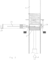
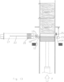
- the Figure 1 shows a part of a channel baler in a top view.
- the illustration is a schematic sectional view in a longitudinal section parallel to a pressing direction P.
- the drawing plane is a horizontal plane of the device which is spanned by the pressing direction P and a transverse direction Q oriented at right angles to the pressing direction P.
- the channel baler has an input area 1 (not shown in detail) into which the material to be pressed is loosely inserted.
- a hydraulic unit 2 is provided to move a press ram 3 from the input area 1 into a bale channel 4 and to compress the material to be pressed there. Several working strokes of the press ram 3 produce a bale 5.
- the bandaging device comprises in detail a supply reel 10 on the left in this illustration and a supply reel 11 on the right.
- the two supply reels 10 and 11 hold a bandaging material in the form of a quasi-endless steel wire for strapping the bales produced.
- a left strand 12 of the bandaging material runs from the supply reel 10 through a left guide means 13, which is formed by two deflection rollers and guides the wire to a wire inlet of the bale channel 4 (not shown in more detail).
- a right strand 14 runs from the supply spool 11 to a right guide means 15, which also has two deflection rollers and guides the wire to a right wire inlet of the bale channel.
- a connecting device 17 is arranged, which in this case is designed as a drilling device due to the use of steel wire.
- This device is described in more detail below.
- the connecting device 17 comprises a first drilling hook 18 and a second drilling hook 19, each of which can be driven separately.
- the first drilling hook 18 is driven by a first drive 20 to rotate about a horizontal axis of rotation which is oriented parallel to the transverse direction Q.
- the second twisting hook 19 is driven by a second drive 21 about a corresponding parallel axis of rotation. Both drives 20, 21 are controlled by a control 22 which is only shown schematically.
- the connecting device 17 further comprises a drawing needle 23, which can be moved parallel to the transverse direction Q by a drive 24 depending on the control 20.
- the design of the drawing needle 23 is known per se from the prior art.
- the guide means 15 On the right side of the bale channel 4, the guide means 15 is arranged on an actuator 25, which is designed to move the guide means 15 not far from the control 20 parallel to the pressing direction P.
- the actuator 25 can in particular be hydraulically driven.
- the right strand 14 of the bandaging material runs over a combined holding and separating means 26, which is not shown in detail here.
- the combined holding and separating means 26 can also be actuated hydraulically and has a concave fixed abutment and a movable, matching wedge-shaped clamping element, between which the bandaging material can be clamped and held.
- a separating means in the form of a shearing device is also provided.
- a first bale 5 has been completely produced and compacted.
- the pressing pressure with which the bale 5 was compacted is maintained by the hydraulic unit and the pressing ram 3 in order to prevent the bale 5 from expanding backwards as long as it has not yet been strapped or bandaged.
- the bale 5 has automatically taken bandaging material with it, namely from the left supply spool 3 and the right supply spool 11.
- the strand 12 lies on the left side of the bale 5 in the pressing direction P.
- the strand 14 lies on the side leading in the pressing direction P and on the right side of the bale 5.
- the two strands 12 and 14 are connected to one another in a tension-resistant manner in a twist 28 which was previously produced by the connecting device 17.
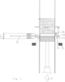
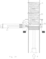
- the Figure 2 shows that starting from the operating state in Figure 1 the drawing needle 23 and in the drive 24 is moved transversely into the bale channel 4, more precisely into a horizontal groove 29 of the press ram 3.
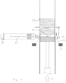
- the Figure 3 shows how the drawing needle 23 has been moved to its right end position.
- One end 30 of the drawing needle 23 has been moved between the right guide means 15 and the combined holding and separating means 26 and under the strand 14 located there into an extreme right position (relative to the pressing direction P).
- the end 30 of the drawing needle 23 has a head, which is not shown in detail here.
- the head essentially comprises a catch element in the manner of a barb and a roller over which the strand 14 can roll.
- the procedural steps that are described in the Figures 1 to 5 are basically the same for a conventional banding device.
- the channel baler illustrated here is intended to provide the option of choosing whether the bale produced should be tied horizontally or not in the horizontal binding shown and to carry out the necessary steps automatically.
- a conventional vertical binding which is not shown in the figures, is present in this channel baler and that this is always is active.
- the bales produced are either strapped vertically and horizontally, as with bale 5 shown here, or only strapped vertically if horizontal strapping is switched off.
- the Figure 6 now shows the process step that is carried out when the next bale, which has not yet been produced, is to be produced without horizontal bandaging.
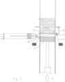
- this step only the downstream twisting hook 19 has been driven and has gripped and twisted the strands 12 and 14 extending from the bale downstream of the pulling needle 23, so that with a second twist 28' the bale 5 is completely strapped and secured against back expansion.
- a separating device assigned to the connecting device 17 has then severed the two strands 12 and 14, so that the bale 5 is free of the virtually endless strands 12 and 14 and can be dispensed.
- the ends of the strands 12 and 14 that were created upstream of the pulling needle 23 initially remain in the area of the upstream twisting hook 18.
- the actuator 25 is controlled to move the guide means 15 parallel to the pressing direction P into a downstream end position. This movement pulls the free end of the right strand 14 out of the upstream twist hook 18. It lies loosely in the groove 29 of the pressing ram 3.
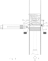
- the Figure 9 shows the binding device of the channel baler in the same condition as the Figure 8 In the meantime, another Bale 35 has been produced. Since the left strand 12 and the right strand 14 are not currently connected to one another, none of the strands 12, 14 were taken along by the bale 35. The bale 35 is not strapped horizontally, but only vertically. The discarded section 31 lies at the front in front of the bale 35 and is strapped together with the bale 35 by the vertical bandaging.
- the channel baler is prepared for the horizontal strapping of the next bale.
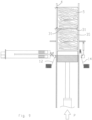
- the Figure 12 shows how the drawing needle 23 has grasped the right strand 14 with its head 30 and taken it into the groove 29 in the backward movement.
- the strand 14 is thereby pulled off the right supply spool 11.
- the free end remains fixed in the combined holding and separating means 26.
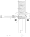
- Figure 14 shows that a twist 36 has been created which firmly connects the left strand 12 and the right strand 14.
- the piece of the right strand 14 located between the pulling needle 23 and the combined holding and separating means 26 is then severed by the separating device of the connecting device 17, the clamping device is released and the severed wire is now present as section 37 in the groove 29. This section 37 is again discarded.
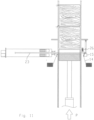
- the Figure 15 finally shows how a third bale 45 was produced, through which the non-horizontally strapped bale 35 was conveyed further in the pressing direction in the bale channel 4.
- the third bale 45 in the sequence shown has in turn taken with it the two strands 12 and 14 connected to each other in the twist 36.
- the channel baler is now in the state of Figure 1
- the bale can now be strapped completely horizontally.
- the operator can now choose whether the next bale should be cross-tied, i.e. strapped both vertically and horizontally, or whether only vertical strapping should be carried out.
- the control system 22 can also make this decision itself, for example by comparing specified parameters of the bales 5, 35 and 45 produced as a function of target values.
- the pulling needle picks up the bale from Figure 15 the right strand 14 and the left strand 12 between the two twist hooks 18 and 19 (as in Fig. 2 to 5 Then the twisting hooks 18 and 19 are controlled simultaneously so that two twists are produced, between which the strands 12 and 14 are then separated. Then one twist remains with the bale 45 and closes its horizontal bandaging, while the next twist is made from the leading side of the bale still to be produced and becomes the starting point for the next horizontal strapping.
- bale following bale 45 is not to be strapped, the process steps are carried out as above using the Figures 2 to 15 described.
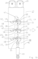
- the connecting device 17 is in a horizontal front view of the Figure 1 right side, i.e. from the side on which the bale channel 4 is located.
- the connecting device 17 comprises a housing 46, which carries the two drives 20 and 21 on its upper side.
- Three groups of twisting hooks 18 and 19 are arranged on the visible front side, which are rotatably mounted in the housing 46.
- three pairs of twisting hooks 18 and 19 arranged one above the other are provided, since the connecting unit 17 is intended for three parallel tracks of bandages.
- the pulling needle 23 of each track can be seen between the twisting hooks 18 and 19, with the view here of the free end 30 on the front side, which in operation, for example, is in Figure 3 grasps and pulls the strand 14.
- the strand 14 runs, as in Figure 16 visible, behind a roller 47, which is arranged in the head 30 of the drawing needle 23 to reduce friction.
- a triple separating device 48 with an actuator 49, a movable knife bar 50, which carries three knives 51, and three stationary counter knives 52.
- the twisting hooks 18 and 19 grasp and twist the strands 12 and 14 either synchronously, as is necessary for the horizontal strapping of successive bales.
- the twisting hooks 18 and 19 can also be driven individually, since, in contrast to the prior art, two separate drives 20 and 21 are provided, each of which is assigned to a group of twisting hooks 18 and 19.
- the Figure 17 shows the connecting device 17 from Figure 16 , whereby not all reference numbers are repeated.
- the actuator 49 of the separating device 48 has been activated and moves the knife bar 50 upwards, so that the knives 51 are moved against the stationary knives 52 and shear off the material strands 12 and 14 lying between the two knives.
- the Figure 17 corresponds to the state of the connecting device 17 in Figure 6 .
- bales with horizontal binding to bales without horizontal binding and vice versa can be carried out automatically by the control system at the discretion of the operating personnel. With appropriate sensors and programming, an autonomous automatic switchover can even take place without operator intervention.
Landscapes
- Engineering & Computer Science (AREA)
- Mechanical Engineering (AREA)
- Basic Packing Technique (AREA)
Applications Claiming Priority (1)
| Application Number | Priority Date | Filing Date | Title |
|---|---|---|---|
| DE102022108056.0A DE102022108056A1 (de) | 2022-04-04 | 2022-04-04 | Kanalballenpresse mit Kreuzabbindung |
Publications (3)
| Publication Number | Publication Date |
|---|---|
| EP4331828A1 EP4331828A1 (de) | 2024-03-06 |
| EP4331828B1 true EP4331828B1 (de) | 2024-12-18 |
| EP4331828C0 EP4331828C0 (de) | 2024-12-18 |
Family
ID=87984607
Family Applications (2)
| Application Number | Title | Priority Date | Filing Date |
|---|---|---|---|
| EP23165735.4A Active EP4331828B1 (de) | 2022-04-04 | 2023-03-30 | Kanalballenpresse mit kreuzabbindung |
| EP23166420.2A Active EP4261028B1 (de) | 2022-04-04 | 2023-04-03 | Kanalballenpresse mit kreuzabbindung |
Family Applications After (1)
| Application Number | Title | Priority Date | Filing Date |
|---|---|---|---|
| EP23166420.2A Active EP4261028B1 (de) | 2022-04-04 | 2023-04-03 | Kanalballenpresse mit kreuzabbindung |
Country Status (3)
| Country | Link |
|---|---|
| EP (2) | EP4331828B1 (pl) |
| DE (1) | DE102022108056A1 (pl) |
| PL (2) | PL4331828T3 (pl) |
Families Citing this family (1)
| Publication number | Priority date | Publication date | Assignee | Title |
|---|---|---|---|---|
| DE102023129957A1 (de) | 2023-10-30 | 2025-04-30 | Unotech Gmbh | Sequentielle Abbindung von verpresstem Material und so hergestellte Ballen |
Family Cites Families (8)
| Publication number | Priority date | Publication date | Assignee | Title |
|---|---|---|---|---|
| DE3406515A1 (de) * | 1984-02-23 | 1985-08-29 | Paal's Packpressen-Fabrik GmbH & Co KG, 4504 Georgsmarienhütte | Maschine zum pressen und umschnueren von ballen |
| DE3918065A1 (de) * | 1989-06-02 | 1990-12-06 | Lindemann Maschfab Gmbh | Vorrichtung zum umschnueren von in einer ballenpresse hergestellten ballen |
| DE4201086C2 (de) | 1992-01-17 | 1993-12-09 | Siegfried Sommerfeld | Verfahren und Vorrichtung zum automatischen Umschnüren von Ballen mit mindestens einem Kunststoffband |
| DE102008000988A1 (de) * | 2008-04-03 | 2009-10-08 | Raussendorf Maschinen- und Gerätebau GmbH | Vorrichtung und Verfahren zur Erzeugung von Großballen in einer Großballenpresse |
| DE102009040506B4 (de) | 2009-09-02 | 2019-02-21 | Hermann Schwelling | Ballenpresse |
| EP2478757B1 (de) * | 2010-09-03 | 2017-11-08 | Hermann Schwelling | Ballenpresse |
| DE102021112704A1 (de) * | 2021-05-17 | 2022-11-17 | Hermann Schwelling | Verfahren zum Verändern der Umreifung sowie Ballenpresse zur Anwendung dieses Verfahrens |
| DE102022121422A1 (de) * | 2022-08-24 | 2024-02-29 | Hermann Schwelling | Verfahren zum Verändern der Umreifung sowie Ballenpresse zur Anwendung dieses Verfahrens |
-
2022
- 2022-04-04 DE DE102022108056.0A patent/DE102022108056A1/de active Pending
-
2023
- 2023-03-30 PL PL23165735.4T patent/PL4331828T3/pl unknown
- 2023-03-30 EP EP23165735.4A patent/EP4331828B1/de active Active
- 2023-04-03 PL PL23166420.2T patent/PL4261028T3/pl unknown
- 2023-04-03 EP EP23166420.2A patent/EP4261028B1/de active Active
Also Published As
| Publication number | Publication date |
|---|---|
| PL4331828T3 (pl) | 2025-04-22 |
| DE102022108056A1 (de) | 2023-10-05 |
| EP4331828C0 (de) | 2024-12-18 |
| EP4261028B1 (de) | 2024-11-20 |
| EP4331828A1 (de) | 2024-03-06 |
| EP4261028A1 (de) | 2023-10-18 |
| PL4261028T3 (pl) | 2025-03-31 |
| EP4261028C0 (de) | 2024-11-20 |
Similar Documents
| Publication | Publication Date | Title |
|---|---|---|
| EP0157898B1 (de) | Vorrichtung zum Binden von Rollballen aus landwirtschaftlichem Erntegut | |
| EP0084680B1 (de) | Vorrichtung zum Umschnüren von Ballen in einer Ballenpresse | |
| EP3323603B1 (de) | Horizontale ballenpresse mit einer ballenabbindevorrichtung | |
| EP3768067B1 (de) | Garnknoteranordnung zum knoten von garn und ballenpressvorrichtung | |
| DE2709248C2 (de) | Verfahren und Vorrichtung zum Umschnüren von Ballen | |
| EP4091808B1 (de) | Verfahren zum verändern der umreifung sowie ballenpresse zur anwendung dieses verfahrens | |
| DE102022121422A1 (de) | Verfahren zum Verändern der Umreifung sowie Ballenpresse zur Anwendung dieses Verfahrens | |
| EP4261028B1 (de) | Kanalballenpresse mit kreuzabbindung | |
| DE102012008554A1 (de) | Kanalballenpresse | |
| DE10047336A1 (de) | Ballenpresse für loses Preßgut | |
| WO1986001974A1 (fr) | Procede et dispositif pour la confection de bottes a partir de vegetaux coupes | |
| DE2105163A1 (de) | Maschine zum Pressen und Umschnüren von Ballen mit Draht | |
| EP2628591B1 (de) | Presse zum Herstellen von Pressballen | |
| DE69613526T2 (de) | Maschine und Verfahren um Rundballen zu Umhüllen | |
| EP2478757B1 (de) | Ballenpresse | |
| EP0027106B1 (de) | Einrichtung zum automatischen Zuführen von Stabmaterial zu einer Biegemaschine für Betonbewehrungsbügel | |
| DE202013012192U1 (de) | Kanalballenpresse | |
| EP3326451B1 (de) | Ballenpresse für loses pressgut | |
| DE102023129957A1 (de) | Sequentielle Abbindung von verpresstem Material und so hergestellte Ballen | |
| EP1234495B1 (de) | Ballenpresse mit einer Bindeeinrichtung | |
| DE19705582A1 (de) | Rundballenpresse | |
| EP1982576A1 (de) | Ballenpresse mit Knotereinrichtung | |
| EP0589257A1 (de) | Ballenpresse, insbesondere zur Verdichtung von Verpackungsmaterial | |
| EP3882166B1 (de) | Verfahren zum einfädeln des unteren umreifungs-stranges sowie ballenpresse zur anwendung dieses verfahrens | |
| DE3406515C2 (pl) |
Legal Events
| Date | Code | Title | Description |
|---|---|---|---|
| APBK | Appeal reference recorded |
Free format text: ORIGINAL CODE: EPIDOSNREFNE |
|
| APBN | Date of receipt of notice of appeal recorded |
Free format text: ORIGINAL CODE: EPIDOSNNOA2E |
|
| APBR | Date of receipt of statement of grounds of appeal recorded |
Free format text: ORIGINAL CODE: EPIDOSNNOA3E |
|
| APBV | Interlocutory revision of appeal recorded |
Free format text: ORIGINAL CODE: EPIDOSNIRAPE |
|
| PUAI | Public reference made under article 153(3) epc to a published international application that has entered the european phase |
Free format text: ORIGINAL CODE: 0009012 |
|
| STAA | Information on the status of an ep patent application or granted ep patent |
Free format text: STATUS: THE APPLICATION HAS BEEN PUBLISHED |
|
| STAA | Information on the status of an ep patent application or granted ep patent |
Free format text: STATUS: REQUEST FOR EXAMINATION WAS MADE |
|
| AK | Designated contracting states |
Kind code of ref document: A1 Designated state(s): AL AT BE BG CH CY CZ DE DK EE ES FI FR GB GR HR HU IE IS IT LI LT LU LV MC ME MK MT NL NO PL PT RO RS SE SI SK SM TR |
|
| 17P | Request for examination filed |
Effective date: 20240216 |
|
| RBV | Designated contracting states (corrected) |
Designated state(s): AL AT BE BG CH CY CZ DE DK EE ES FI FR GB GR HR HU IE IS IT LI LT LU LV MC ME MK MT NL NO PL PT RO RS SE SI SK SM TR |
|
| GRAP | Despatch of communication of intention to grant a patent |
Free format text: ORIGINAL CODE: EPIDOSNIGR1 |
|
| GRAP | Despatch of communication of intention to grant a patent |
Free format text: ORIGINAL CODE: EPIDOSNIGR1 |
|
| STAA | Information on the status of an ep patent application or granted ep patent |
Free format text: STATUS: GRANT OF PATENT IS INTENDED |
|
| RIC1 | Information provided on ipc code assigned before grant |
Ipc: B30B 15/00 20060101ALI20240517BHEP Ipc: B65B 13/02 20060101ALI20240517BHEP Ipc: B65B 13/04 20060101ALI20240517BHEP Ipc: B65B 13/20 20060101ALI20240517BHEP Ipc: B65B 13/28 20060101ALI20240517BHEP Ipc: B65B 27/12 20060101ALI20240517BHEP Ipc: B65B 57/12 20060101ALI20240517BHEP Ipc: B65B 59/00 20060101ALI20240517BHEP Ipc: B65B 59/02 20060101ALI20240517BHEP Ipc: B65B 9/02 20060101ALI20240517BHEP Ipc: B30B 9/30 20060101AFI20240517BHEP |
|
| INTG | Intention to grant announced |
Effective date: 20240614 |
|
| GRAS | Grant fee paid |
Free format text: ORIGINAL CODE: EPIDOSNIGR3 |
|
| GRAA | (expected) grant |
Free format text: ORIGINAL CODE: 0009210 |
|
| STAA | Information on the status of an ep patent application or granted ep patent |
Free format text: STATUS: THE PATENT HAS BEEN GRANTED |
|
| AK | Designated contracting states |
Kind code of ref document: B1 Designated state(s): AL AT BE BG CH CY CZ DE DK EE ES FI FR GB GR HR HU IE IS IT LI LT LU LV MC ME MK MT NL NO PL PT RO RS SE SI SK SM TR |
|
| REG | Reference to a national code |
Ref country code: CH Ref legal event code: EP |
|
| REG | Reference to a national code |
Ref country code: DE Ref legal event code: R096 Ref document number: 502023000393 Country of ref document: DE |
|
| REG | Reference to a national code |
Ref country code: IE Ref legal event code: FG4D Free format text: LANGUAGE OF EP DOCUMENT: GERMAN |
|
| U01 | Request for unitary effect filed |
Effective date: 20241219 |
|
| U07 | Unitary effect registered |
Designated state(s): AT BE BG DE DK EE FI FR IT LT LU LV MT NL PT RO SE SI Effective date: 20250113 |
|
| U20 | Renewal fee for the european patent with unitary effect paid |
Year of fee payment: 3 Effective date: 20250114 |
|
| PG25 | Lapsed in a contracting state [announced via postgrant information from national office to epo] |
Ref country code: HR Free format text: LAPSE BECAUSE OF FAILURE TO SUBMIT A TRANSLATION OF THE DESCRIPTION OR TO PAY THE FEE WITHIN THE PRESCRIBED TIME-LIMIT Effective date: 20241218 |
|
| PG25 | Lapsed in a contracting state [announced via postgrant information from national office to epo] |
Ref country code: NO Free format text: LAPSE BECAUSE OF FAILURE TO SUBMIT A TRANSLATION OF THE DESCRIPTION OR TO PAY THE FEE WITHIN THE PRESCRIBED TIME-LIMIT Effective date: 20250318 |
|
| PG25 | Lapsed in a contracting state [announced via postgrant information from national office to epo] |
Ref country code: GR Free format text: LAPSE BECAUSE OF FAILURE TO SUBMIT A TRANSLATION OF THE DESCRIPTION OR TO PAY THE FEE WITHIN THE PRESCRIBED TIME-LIMIT Effective date: 20250319 |
|
| PG25 | Lapsed in a contracting state [announced via postgrant information from national office to epo] |
Ref country code: RS Free format text: LAPSE BECAUSE OF FAILURE TO SUBMIT A TRANSLATION OF THE DESCRIPTION OR TO PAY THE FEE WITHIN THE PRESCRIBED TIME-LIMIT Effective date: 20250318 |
|
| PG25 | Lapsed in a contracting state [announced via postgrant information from national office to epo] |
Ref country code: SM Free format text: LAPSE BECAUSE OF FAILURE TO SUBMIT A TRANSLATION OF THE DESCRIPTION OR TO PAY THE FEE WITHIN THE PRESCRIBED TIME-LIMIT Effective date: 20241218 |
|
| PG25 | Lapsed in a contracting state [announced via postgrant information from national office to epo] |
Ref country code: ES Free format text: LAPSE BECAUSE OF FAILURE TO SUBMIT A TRANSLATION OF THE DESCRIPTION OR TO PAY THE FEE WITHIN THE PRESCRIBED TIME-LIMIT Effective date: 20241218 |
|
| PG25 | Lapsed in a contracting state [announced via postgrant information from national office to epo] |
Ref country code: IS Free format text: LAPSE BECAUSE OF FAILURE TO SUBMIT A TRANSLATION OF THE DESCRIPTION OR TO PAY THE FEE WITHIN THE PRESCRIBED TIME-LIMIT Effective date: 20250418 |
|
| PG25 | Lapsed in a contracting state [announced via postgrant information from national office to epo] |
Ref country code: SK Free format text: LAPSE BECAUSE OF FAILURE TO SUBMIT A TRANSLATION OF THE DESCRIPTION OR TO PAY THE FEE WITHIN THE PRESCRIBED TIME-LIMIT Effective date: 20241218 |
|
| PG25 | Lapsed in a contracting state [announced via postgrant information from national office to epo] |
Ref country code: CZ Free format text: LAPSE BECAUSE OF FAILURE TO SUBMIT A TRANSLATION OF THE DESCRIPTION OR TO PAY THE FEE WITHIN THE PRESCRIBED TIME-LIMIT Effective date: 20241218 |
|
| PG25 | Lapsed in a contracting state [announced via postgrant information from national office to epo] |
Ref country code: MC Free format text: LAPSE BECAUSE OF FAILURE TO SUBMIT A TRANSLATION OF THE DESCRIPTION OR TO PAY THE FEE WITHIN THE PRESCRIBED TIME-LIMIT Effective date: 20241218 |
|
| PLBE | No opposition filed within time limit |
Free format text: ORIGINAL CODE: 0009261 |
|
| STAA | Information on the status of an ep patent application or granted ep patent |
Free format text: STATUS: NO OPPOSITION FILED WITHIN TIME LIMIT |
|
| 26N | No opposition filed |
Effective date: 20250919 |
|
| PG25 | Lapsed in a contracting state [announced via postgrant information from national office to epo] |
Ref country code: IE Free format text: LAPSE BECAUSE OF NON-PAYMENT OF DUE FEES Effective date: 20250330 |
|
| PGFP | Annual fee paid to national office [announced via postgrant information from national office to epo] |
Ref country code: PL Payment date: 20260312 Year of fee payment: 4 |
|
| U20 | Renewal fee for the european patent with unitary effect paid |
Year of fee payment: 4 Effective date: 20260327 |