EP4331481A2 - Wundtherapiesystem mit wundvolumenschätzung - Google Patents
Wundtherapiesystem mit wundvolumenschätzung Download PDFInfo
- Publication number
- EP4331481A2 EP4331481A2 EP24151949.5A EP24151949A EP4331481A2 EP 4331481 A2 EP4331481 A2 EP 4331481A2 EP 24151949 A EP24151949 A EP 24151949A EP 4331481 A2 EP4331481 A2 EP 4331481A2
- Authority
- EP
- European Patent Office
- Prior art keywords
- wound
- negative pressure
- pressure
- circuit
- volume
- Prior art date
- Legal status (The legal status is an assumption and is not a legal conclusion. Google has not performed a legal analysis and makes no representation as to the accuracy of the status listed.)
- Pending
Links
- 206010052428 Wound Diseases 0.000 title claims abstract description 488
- 208000027418 Wounds and injury Diseases 0.000 title claims abstract description 488
- 238000002560 therapeutic procedure Methods 0.000 title claims abstract description 155
- 230000004044 response Effects 0.000 claims abstract description 151
- 238000012956 testing procedure Methods 0.000 claims abstract description 113
- 238000009530 blood pressure measurement Methods 0.000 claims abstract description 24
- 239000012530 fluid Substances 0.000 claims description 180
- 238000012549 training Methods 0.000 claims description 137
- 238000000034 method Methods 0.000 claims description 118
- 238000010926 purge Methods 0.000 claims description 20
- 230000008569 process Effects 0.000 description 46
- 230000035876 healing Effects 0.000 description 15
- 238000004891 communication Methods 0.000 description 13
- 230000006870 function Effects 0.000 description 12
- 238000009581 negative-pressure wound therapy Methods 0.000 description 10
- 230000004913 activation Effects 0.000 description 9
- 238000001994 activation Methods 0.000 description 9
- 238000010586 diagram Methods 0.000 description 9
- 238000013528 artificial neural network Methods 0.000 description 8
- 230000007423 decrease Effects 0.000 description 8
- 238000003062 neural network model Methods 0.000 description 8
- 238000010801 machine learning Methods 0.000 description 7
- 238000012545 processing Methods 0.000 description 7
- 210000000416 exudates and transudate Anatomy 0.000 description 6
- 238000012417 linear regression Methods 0.000 description 4
- 238000005259 measurement Methods 0.000 description 4
- 238000012544 monitoring process Methods 0.000 description 4
- 238000012986 modification Methods 0.000 description 3
- 230000004048 modification Effects 0.000 description 3
- 238000005086 pumping Methods 0.000 description 3
- 238000012360 testing method Methods 0.000 description 3
- 230000003213 activating effect Effects 0.000 description 2
- 230000008901 benefit Effects 0.000 description 2
- 230000001413 cellular effect Effects 0.000 description 2
- 230000008859 change Effects 0.000 description 2
- 238000003066 decision tree Methods 0.000 description 2
- 238000013135 deep learning Methods 0.000 description 2
- 238000001514 detection method Methods 0.000 description 2
- 230000000694 effects Effects 0.000 description 2
- 230000002068 genetic effect Effects 0.000 description 2
- 230000001939 inductive effect Effects 0.000 description 2
- 239000007788 liquid Substances 0.000 description 2
- 238000013178 mathematical model Methods 0.000 description 2
- 230000003287 optical effect Effects 0.000 description 2
- 238000013488 ordinary least square regression Methods 0.000 description 2
- 230000002787 reinforcement Effects 0.000 description 2
- 238000012706 support-vector machine Methods 0.000 description 2
- 230000029663 wound healing Effects 0.000 description 2
- 102000004506 Blood Proteins Human genes 0.000 description 1
- 108010017384 Blood Proteins Proteins 0.000 description 1
- 206010061218 Inflammation Diseases 0.000 description 1
- 239000003242 anti bacterial agent Substances 0.000 description 1
- 238000003491 array Methods 0.000 description 1
- 230000001580 bacterial effect Effects 0.000 description 1
- 239000011324 bead Substances 0.000 description 1
- 230000003115 biocidal effect Effects 0.000 description 1
- 210000004369 blood Anatomy 0.000 description 1
- 239000008280 blood Substances 0.000 description 1
- 210000001772 blood platelet Anatomy 0.000 description 1
- 230000005465 channeling Effects 0.000 description 1
- 239000003086 colorant Substances 0.000 description 1
- 238000010276 construction Methods 0.000 description 1
- 238000013461 design Methods 0.000 description 1
- 210000003743 erythrocyte Anatomy 0.000 description 1
- 230000002209 hydrophobic effect Effects 0.000 description 1
- 230000004054 inflammatory process Effects 0.000 description 1
- 230000004941 influx Effects 0.000 description 1
- 238000009434 installation Methods 0.000 description 1
- 230000003902 lesion Effects 0.000 description 1
- 210000000265 leukocyte Anatomy 0.000 description 1
- 239000000463 material Substances 0.000 description 1
- 239000002245 particle Substances 0.000 description 1
- 239000007787 solid Substances 0.000 description 1
- 238000006467 substitution reaction Methods 0.000 description 1
- 230000000699 topical effect Effects 0.000 description 1
- XLYOFNOQVPJJNP-UHFFFAOYSA-N water Substances O XLYOFNOQVPJJNP-UHFFFAOYSA-N 0.000 description 1
Images


Classifications
-
- A—HUMAN NECESSITIES
- A61—MEDICAL OR VETERINARY SCIENCE; HYGIENE
- A61B—DIAGNOSIS; SURGERY; IDENTIFICATION
- A61B5/00—Measuring for diagnostic purposes; Identification of persons
- A61B5/103—Detecting, measuring or recording devices for testing the shape, pattern, colour, size or movement of the body or parts thereof, for diagnostic purposes
- A61B5/107—Measuring physical dimensions, e.g. size of the entire body or parts thereof
- A61B5/1073—Measuring volume, e.g. of limbs
-
- A—HUMAN NECESSITIES
- A61—MEDICAL OR VETERINARY SCIENCE; HYGIENE
- A61B—DIAGNOSIS; SURGERY; IDENTIFICATION
- A61B5/00—Measuring for diagnostic purposes; Identification of persons
- A61B5/103—Detecting, measuring or recording devices for testing the shape, pattern, colour, size or movement of the body or parts thereof, for diagnostic purposes
- A61B5/107—Measuring physical dimensions, e.g. size of the entire body or parts thereof
- A61B5/1076—Measuring physical dimensions, e.g. size of the entire body or parts thereof for measuring dimensions inside body cavities, e.g. using catheters
-
- A—HUMAN NECESSITIES
- A61—MEDICAL OR VETERINARY SCIENCE; HYGIENE
- A61B—DIAGNOSIS; SURGERY; IDENTIFICATION
- A61B5/00—Measuring for diagnostic purposes; Identification of persons
- A61B5/44—Detecting, measuring or recording for evaluating the integumentary system, e.g. skin, hair or nails
- A61B5/441—Skin evaluation, e.g. for skin disorder diagnosis
- A61B5/445—Evaluating skin irritation or skin trauma, e.g. rash, eczema, wound, bed sore
-
- A61F13/05—
-
- A—HUMAN NECESSITIES
- A61—MEDICAL OR VETERINARY SCIENCE; HYGIENE
- A61M—DEVICES FOR INTRODUCING MEDIA INTO, OR ONTO, THE BODY; DEVICES FOR TRANSDUCING BODY MEDIA OR FOR TAKING MEDIA FROM THE BODY; DEVICES FOR PRODUCING OR ENDING SLEEP OR STUPOR
- A61M1/00—Suction or pumping devices for medical purposes; Devices for carrying-off, for treatment of, or for carrying-over, body-liquids; Drainage systems
- A61M1/71—Suction drainage systems
- A61M1/73—Suction drainage systems comprising sensors or indicators for physical values
-
- A—HUMAN NECESSITIES
- A61—MEDICAL OR VETERINARY SCIENCE; HYGIENE
- A61M—DEVICES FOR INTRODUCING MEDIA INTO, OR ONTO, THE BODY; DEVICES FOR TRANSDUCING BODY MEDIA OR FOR TAKING MEDIA FROM THE BODY; DEVICES FOR PRODUCING OR ENDING SLEEP OR STUPOR
- A61M1/00—Suction or pumping devices for medical purposes; Devices for carrying-off, for treatment of, or for carrying-over, body-liquids; Drainage systems
- A61M1/71—Suction drainage systems
- A61M1/77—Suction-irrigation systems
-
- A—HUMAN NECESSITIES
- A61—MEDICAL OR VETERINARY SCIENCE; HYGIENE
- A61M—DEVICES FOR INTRODUCING MEDIA INTO, OR ONTO, THE BODY; DEVICES FOR TRANSDUCING BODY MEDIA OR FOR TAKING MEDIA FROM THE BODY; DEVICES FOR PRODUCING OR ENDING SLEEP OR STUPOR
- A61M1/00—Suction or pumping devices for medical purposes; Devices for carrying-off, for treatment of, or for carrying-over, body-liquids; Drainage systems
- A61M1/84—Drainage tubes; Aspiration tips
- A61M1/85—Drainage tubes; Aspiration tips with gas or fluid supply means, e.g. for supplying rinsing fluids or anticoagulants
-
- A—HUMAN NECESSITIES
- A61—MEDICAL OR VETERINARY SCIENCE; HYGIENE
- A61M—DEVICES FOR INTRODUCING MEDIA INTO, OR ONTO, THE BODY; DEVICES FOR TRANSDUCING BODY MEDIA OR FOR TAKING MEDIA FROM THE BODY; DEVICES FOR PRODUCING OR ENDING SLEEP OR STUPOR
- A61M1/00—Suction or pumping devices for medical purposes; Devices for carrying-off, for treatment of, or for carrying-over, body-liquids; Drainage systems
- A61M1/90—Negative pressure wound therapy devices, i.e. devices for applying suction to a wound to promote healing, e.g. including a vacuum dressing
- A61M1/92—Negative pressure wound therapy devices, i.e. devices for applying suction to a wound to promote healing, e.g. including a vacuum dressing with liquid supply means
-
- A—HUMAN NECESSITIES
- A61—MEDICAL OR VETERINARY SCIENCE; HYGIENE
- A61M—DEVICES FOR INTRODUCING MEDIA INTO, OR ONTO, THE BODY; DEVICES FOR TRANSDUCING BODY MEDIA OR FOR TAKING MEDIA FROM THE BODY; DEVICES FOR PRODUCING OR ENDING SLEEP OR STUPOR
- A61M1/00—Suction or pumping devices for medical purposes; Devices for carrying-off, for treatment of, or for carrying-over, body-liquids; Drainage systems
- A61M1/90—Negative pressure wound therapy devices, i.e. devices for applying suction to a wound to promote healing, e.g. including a vacuum dressing
- A61M1/96—Suction control thereof
- A61M1/962—Suction control thereof having pumping means on the suction site, e.g. miniature pump on dressing or dressing capable of exerting suction
-
- A—HUMAN NECESSITIES
- A61—MEDICAL OR VETERINARY SCIENCE; HYGIENE
- A61M—DEVICES FOR INTRODUCING MEDIA INTO, OR ONTO, THE BODY; DEVICES FOR TRANSDUCING BODY MEDIA OR FOR TAKING MEDIA FROM THE BODY; DEVICES FOR PRODUCING OR ENDING SLEEP OR STUPOR
- A61M1/00—Suction or pumping devices for medical purposes; Devices for carrying-off, for treatment of, or for carrying-over, body-liquids; Drainage systems
- A61M1/90—Negative pressure wound therapy devices, i.e. devices for applying suction to a wound to promote healing, e.g. including a vacuum dressing
- A61M1/96—Suction control thereof
- A61M1/964—Suction control thereof having venting means on or near the dressing
-
- A—HUMAN NECESSITIES
- A61—MEDICAL OR VETERINARY SCIENCE; HYGIENE
- A61M—DEVICES FOR INTRODUCING MEDIA INTO, OR ONTO, THE BODY; DEVICES FOR TRANSDUCING BODY MEDIA OR FOR TAKING MEDIA FROM THE BODY; DEVICES FOR PRODUCING OR ENDING SLEEP OR STUPOR
- A61M3/00—Medical syringes, e.g. enemata; Irrigators
- A61M3/02—Enemata; Irrigators
- A61M3/0204—Physical characteristics of the irrigation fluid, e.g. conductivity or turbidity
- A61M3/022—Volume; Flow rate
-
- A—HUMAN NECESSITIES
- A61—MEDICAL OR VETERINARY SCIENCE; HYGIENE
- A61M—DEVICES FOR INTRODUCING MEDIA INTO, OR ONTO, THE BODY; DEVICES FOR TRANSDUCING BODY MEDIA OR FOR TAKING MEDIA FROM THE BODY; DEVICES FOR PRODUCING OR ENDING SLEEP OR STUPOR
- A61M3/00—Medical syringes, e.g. enemata; Irrigators
- A61M3/02—Enemata; Irrigators
- A61M3/0233—Enemata; Irrigators characterised by liquid supply means, e.g. from pressurised reservoirs
- A61M3/0254—Enemata; Irrigators characterised by liquid supply means, e.g. from pressurised reservoirs the liquid being pumped
- A61M3/0258—Enemata; Irrigators characterised by liquid supply means, e.g. from pressurised reservoirs the liquid being pumped by means of electric pumps
-
- A—HUMAN NECESSITIES
- A61—MEDICAL OR VETERINARY SCIENCE; HYGIENE
- A61F—FILTERS IMPLANTABLE INTO BLOOD VESSELS; PROSTHESES; DEVICES PROVIDING PATENCY TO, OR PREVENTING COLLAPSING OF, TUBULAR STRUCTURES OF THE BODY, e.g. STENTS; ORTHOPAEDIC, NURSING OR CONTRACEPTIVE DEVICES; FOMENTATION; TREATMENT OR PROTECTION OF EYES OR EARS; BANDAGES, DRESSINGS OR ABSORBENT PADS; FIRST-AID KITS
- A61F13/00—Bandages or dressings; Absorbent pads
- A61F2013/00089—Wound bandages
- A61F2013/0017—Wound bandages possibility of applying fluid
- A61F2013/00174—Wound bandages possibility of applying fluid possibility of applying pressure
-
- A—HUMAN NECESSITIES
- A61—MEDICAL OR VETERINARY SCIENCE; HYGIENE
- A61F—FILTERS IMPLANTABLE INTO BLOOD VESSELS; PROSTHESES; DEVICES PROVIDING PATENCY TO, OR PREVENTING COLLAPSING OF, TUBULAR STRUCTURES OF THE BODY, e.g. STENTS; ORTHOPAEDIC, NURSING OR CONTRACEPTIVE DEVICES; FOMENTATION; TREATMENT OR PROTECTION OF EYES OR EARS; BANDAGES, DRESSINGS OR ABSORBENT PADS; FIRST-AID KITS
- A61F13/00—Bandages or dressings; Absorbent pads
- A61F13/15—Absorbent pads, e.g. sanitary towels, swabs or tampons for external or internal application to the body; Supporting or fastening means therefor; Tampon applicators
- A61F13/84—Accessories, not otherwise provided for, for absorbent pads
- A61F2013/8494—Accessories, not otherwise provided for, for absorbent pads including pumping devices
-
- A—HUMAN NECESSITIES
- A61—MEDICAL OR VETERINARY SCIENCE; HYGIENE
- A61M—DEVICES FOR INTRODUCING MEDIA INTO, OR ONTO, THE BODY; DEVICES FOR TRANSDUCING BODY MEDIA OR FOR TAKING MEDIA FROM THE BODY; DEVICES FOR PRODUCING OR ENDING SLEEP OR STUPOR
- A61M1/00—Suction or pumping devices for medical purposes; Devices for carrying-off, for treatment of, or for carrying-over, body-liquids; Drainage systems
- A61M1/71—Suction drainage systems
- A61M1/73—Suction drainage systems comprising sensors or indicators for physical values
- A61M1/732—Visual indicating means for vacuum pressure
-
- A—HUMAN NECESSITIES
- A61—MEDICAL OR VETERINARY SCIENCE; HYGIENE
- A61M—DEVICES FOR INTRODUCING MEDIA INTO, OR ONTO, THE BODY; DEVICES FOR TRANSDUCING BODY MEDIA OR FOR TAKING MEDIA FROM THE BODY; DEVICES FOR PRODUCING OR ENDING SLEEP OR STUPOR
- A61M1/00—Suction or pumping devices for medical purposes; Devices for carrying-off, for treatment of, or for carrying-over, body-liquids; Drainage systems
- A61M1/71—Suction drainage systems
- A61M1/74—Suction control
- A61M1/742—Suction control by changing the size of a vent
-
- A—HUMAN NECESSITIES
- A61—MEDICAL OR VETERINARY SCIENCE; HYGIENE
- A61M—DEVICES FOR INTRODUCING MEDIA INTO, OR ONTO, THE BODY; DEVICES FOR TRANSDUCING BODY MEDIA OR FOR TAKING MEDIA FROM THE BODY; DEVICES FOR PRODUCING OR ENDING SLEEP OR STUPOR
- A61M2205/00—General characteristics of the apparatus
- A61M2205/15—Detection of leaks
-
- A—HUMAN NECESSITIES
- A61—MEDICAL OR VETERINARY SCIENCE; HYGIENE
- A61M—DEVICES FOR INTRODUCING MEDIA INTO, OR ONTO, THE BODY; DEVICES FOR TRANSDUCING BODY MEDIA OR FOR TAKING MEDIA FROM THE BODY; DEVICES FOR PRODUCING OR ENDING SLEEP OR STUPOR
- A61M2205/00—General characteristics of the apparatus
- A61M2205/33—Controlling, regulating or measuring
- A61M2205/3331—Pressure; Flow
- A61M2205/3334—Measuring or controlling the flow rate
-
- A—HUMAN NECESSITIES
- A61—MEDICAL OR VETERINARY SCIENCE; HYGIENE
- A61M—DEVICES FOR INTRODUCING MEDIA INTO, OR ONTO, THE BODY; DEVICES FOR TRANSDUCING BODY MEDIA OR FOR TAKING MEDIA FROM THE BODY; DEVICES FOR PRODUCING OR ENDING SLEEP OR STUPOR
- A61M2205/00—General characteristics of the apparatus
- A61M2205/33—Controlling, regulating or measuring
- A61M2205/3331—Pressure; Flow
- A61M2205/3337—Controlling, regulating pressure or flow by means of a valve by-passing a pump
-
- A—HUMAN NECESSITIES
- A61—MEDICAL OR VETERINARY SCIENCE; HYGIENE
- A61M—DEVICES FOR INTRODUCING MEDIA INTO, OR ONTO, THE BODY; DEVICES FOR TRANSDUCING BODY MEDIA OR FOR TAKING MEDIA FROM THE BODY; DEVICES FOR PRODUCING OR ENDING SLEEP OR STUPOR
- A61M2205/00—General characteristics of the apparatus
- A61M2205/33—Controlling, regulating or measuring
- A61M2205/3331—Pressure; Flow
- A61M2205/3344—Measuring or controlling pressure at the body treatment site
-
- A—HUMAN NECESSITIES
- A61—MEDICAL OR VETERINARY SCIENCE; HYGIENE
- A61M—DEVICES FOR INTRODUCING MEDIA INTO, OR ONTO, THE BODY; DEVICES FOR TRANSDUCING BODY MEDIA OR FOR TAKING MEDIA FROM THE BODY; DEVICES FOR PRODUCING OR ENDING SLEEP OR STUPOR
- A61M2205/00—General characteristics of the apparatus
- A61M2205/33—Controlling, regulating or measuring
- A61M2205/3379—Masses, volumes, levels of fluids in reservoirs, flow rates
-
- A—HUMAN NECESSITIES
- A61—MEDICAL OR VETERINARY SCIENCE; HYGIENE
- A61M—DEVICES FOR INTRODUCING MEDIA INTO, OR ONTO, THE BODY; DEVICES FOR TRANSDUCING BODY MEDIA OR FOR TAKING MEDIA FROM THE BODY; DEVICES FOR PRODUCING OR ENDING SLEEP OR STUPOR
- A61M2205/00—General characteristics of the apparatus
- A61M2205/70—General characteristics of the apparatus with testing or calibration facilities
- A61M2205/702—General characteristics of the apparatus with testing or calibration facilities automatically during use
-
- A—HUMAN NECESSITIES
- A61—MEDICAL OR VETERINARY SCIENCE; HYGIENE
- A61M—DEVICES FOR INTRODUCING MEDIA INTO, OR ONTO, THE BODY; DEVICES FOR TRANSDUCING BODY MEDIA OR FOR TAKING MEDIA FROM THE BODY; DEVICES FOR PRODUCING OR ENDING SLEEP OR STUPOR
- A61M3/00—Medical syringes, e.g. enemata; Irrigators
- A61M3/02—Enemata; Irrigators
- A61M3/0202—Enemata; Irrigators with electronic control means or interfaces
-
- A—HUMAN NECESSITIES
- A61—MEDICAL OR VETERINARY SCIENCE; HYGIENE
- A61M—DEVICES FOR INTRODUCING MEDIA INTO, OR ONTO, THE BODY; DEVICES FOR TRANSDUCING BODY MEDIA OR FOR TAKING MEDIA FROM THE BODY; DEVICES FOR PRODUCING OR ENDING SLEEP OR STUPOR
- A61M35/00—Devices for applying media, e.g. remedies, on the human body
- A61M35/003—Portable hand-held applicators having means for dispensing or spreading integral media
- A61M35/006—Portable hand-held applicators having means for dispensing or spreading integral media using sponges, foams, absorbent pads or swabs as spreading means
-
- A—HUMAN NECESSITIES
- A61—MEDICAL OR VETERINARY SCIENCE; HYGIENE
- A61M—DEVICES FOR INTRODUCING MEDIA INTO, OR ONTO, THE BODY; DEVICES FOR TRANSDUCING BODY MEDIA OR FOR TAKING MEDIA FROM THE BODY; DEVICES FOR PRODUCING OR ENDING SLEEP OR STUPOR
- A61M35/00—Devices for applying media, e.g. remedies, on the human body
- A61M35/30—Gas therapy for therapeutic treatment of the skin
Definitions
- the present disclosure relates generally to a wound therapy system, and more particularly to a wound therapy system configured to estimate the volume of a wound.
- Negative pressure wound therapy is a type of wound therapy that involves applying a negative pressure to a wound site to promote wound healing.
- Some wound treatment systems apply negative pressure to a wound using a pneumatic pump to generate the negative pressure and flow required.
- Recent advancements in wound healing with NPWT involve applying topical fluids to wounds to work in combination with NPWT.
- it can be difficult to accurately monitor and track healing progression over time.
- a wound therapy system including a negative pressure circuit configured to apply negative pressure to a wound, a pump fluidly coupled to the negative pressure circuit and operable to control the negative pressure within the negative pressure circuit, a pressure sensor configured to measure the negative pressure within the negative pressure circuit or at the wound and a controller communicably coupled to the pump and the pressure sensor.
- the controller is configured to execute a pressure testing procedure including applying a pressure stimulus to the negative pressure circuit, observe a dynamic pressure response of the negative pressure circuit to the pressure stimulus using pressure measurements recorded by the pressure sensor, and estimate a wound volume of the wound based on the dynamic pressure response.
- the negative pressure circuit includes a wound dressing sealable to skin surrounding the wound.
- the negative pressure circuit includes at least one of an instillation fluid canister containing instillation fluid for delivery to the wound or a removed fluid canister containing fluid removed from the wound.
- the negative pressure circuit includes tubing fluidly connecting the pump with the wound.
- the negative pressure circuit includes a wound dressing sealable to skin surrounding the wound, at least one of an instillation fluid canister containing instillation fluid for delivery to the wound or a removed fluid canister containing fluid removed from the wound, and tubing fluidly connecting the instillation fluid canister or the removed fluid canister with the wound dressing.
- the controller is configured to operate the pump to establish the negative pressure within the negative pressure circuit.
- the testing procedure includes operating the pump to establish the negative pressure within the negative pressure circuit and applying the pressure stimulus after the negative pressure has been established within the negative pressure circuit.
- the system includes a valve coupled to the negative pressure circuit and operable to controllably vent the negative pressure circuit.
- applying the pressure stimulus includes opening the valve to allow airflow into the negative pressure circuit for a predetermined amount of time and closing the valve after the predetermined amount of time has elapsed.
- applying the pressure stimulus further includes waiting for another predetermined amount of time after closing the valve and repeating the opening, closing, and waiting steps until the negative pressure reaches a threshold pressure value.
- applying the pressure stimulus further includes operating the pump while the valve is closed to mitigate air leakage into the negative pressure circuit.
- the dynamic pressure response of the negative pressure circuit is characterized by a depth of purge parameter defined as a difference between a measured value of the negative pressure before the valve is opened and a measured value of the negative pressure while the valve is open.
- the dynamic pressure response of the negative pressure circuit is characterized by a rebound parameter defined as a difference between a measured value of the negative pressure after the valve is closed and a measured value of the negative pressure while the valve is open.
- the dynamic pressure response of the negative pressure circuit is characterized by a delta parameter defined as a difference between a measured value of the negative pressure before the valve is opened and a measured value of the negative pressure after the valve is closed.
- the dynamic pressure response of the negative pressure circuit is characterized by a leak rate parameter defined as a rate at which the negative pressure changes while the valve is closed.
- the wound therapy system includes an orifice located along the negative pressure circuit and configured to allow air to leak into the negative pressure circuit at a known rate.
- applying the pressure stimulus includes operating the pump to achieve a predetermined negative pressure within the negative pressure circuit and deactivating the pump upon reaching the predetermined negative pressure within the negative pressure circuit.
- estimating the wound volume based on the dynamic pressure response includes determining values for one or more parameters that characterize the dynamic pressure response and applying the values of the one or more parameters as inputs to a model that defines a relationship between the one or more parameters and the wound volume.
- the model that defines the relationship between the one or more parameters and the wound volume is a polynomial approximation model. In some embodiments, the model that defines the relationship between the one or more parameters and the wound volume is a neural network.
- the controller is configured to generate the model that defines the relationship between the one or more parameters and the wound volume by executing a training procedure comprising applying the pressure stimulus to training circuit having a known volume, observing a dynamic pressure response of the training circuit to the pressure stimulus using pressure measurements recorded by the pressure sensor and associating the known volume with the dynamic pressure response of the training circuit.
- generating the model further includes repeating the training procedure for a plurality of known volumes, observing the dynamic pressure response of the training circuit for each of the plurality of known volumes, and generating a correlation between the plurality of known volumes and the dynamic pressure response of the training circuit.
- the controller is configured to execute the pressure testing procedure, observe the dynamic pressure response, and estimate the wound volume at a plurality of times during wound treatment.
- the controller can be configured to determine healing progression based on changes in the wound volume during wound treatment.
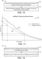
- the controller is configured to determine a volume of instillation fluid to deliver to the wound based on the estimated wound volume.
- the controller can be configured to operate the pump to deliver the volume of instillation fluid to the wound.
- the controller is configured to determine the volume of instillation fluid to deliver to the wound by multiplying the estimated wound volume by a fluid instillation factor.
- the fluid instillation factor is less than one such that less than the total wound volume is filled with the instillation fluid. In some embodiments, the fluid instillation factor is between approximately 0.2 and approximately 0.8.
- Another implementation of the present disclosure is a method for estimating a wound volume of a wound.
- the method includes applying negative pressure to a wound using a negative pressure circuit, operating a pump fluidly coupled to the negative pressure circuit to control the negative pressure within the negative pressure circuit, measuring the negative pressure within the negative pressure circuit or at the wound, executing a pressure testing procedure including applying a pressure stimulus to the negative pressure circuit, observing a dynamic pressure response of the negative pressure circuit to the pressure stimulus using measurements of the negative pressure, and estimating the wound volume based on the dynamic pressure response.
- the negative pressure circuit includes a wound dressing sealable to skin surrounding the wound.
- the negative pressure circuit includes at least one of an instillation fluid canister containing instillation fluid for delivery to the wound or a removed fluid canister containing fluid removed from the wound.
- the negative pressure circuit includes tubing fluidly connecting the pump with the wound.
- the negative pressure circuit includes a wound dressing sealable to skin surrounding the wound, at least one of an instillation fluid canister containing instillation fluid for delivery to the wound or a removed fluid canister containing fluid removed from the wound, and tubing fluidly connecting the instillation fluid canister or the removed fluid canister with the wound dressing.
- the method includes operating the pump to establish the negative pressure within the negative pressure circuit.
- the testing procedure includes operating the pump to establish the negative pressure within the negative pressure circuit and applying the pressure stimulus after the negative pressure has been established within the negative pressure circuit.
- the method includes operating a valve coupled to the negative pressure circuit to controllably vent the negative pressure circuit.
- applying the pressure stimulus includes opening the valve to allow airflow into the negative pressure circuit for a predetermined amount of time and closing the valve after the predetermined amount of time has elapsed.
- applying the pressure stimulus further includes waiting for another predetermined amount of time after closing the valve and repeating the opening, closing, and waiting steps until the negative pressure reaches a threshold pressure value. In some embodiments, applying the pressure stimulus further includes operating the pump while the valve is closed to mitigate air leakage into the negative pressure circuit.
- the dynamic pressure response of the negative pressure circuit is characterized by a depth of purge parameter defined as a difference between a measured value of the negative pressure before the valve is opened and a measured value of the negative pressure while the valve is open.
- the dynamic pressure response of the negative pressure circuit is characterized by a rebound parameter defined as a difference between a measured value of the negative pressure after the valve is closed and a measured value of the negative pressure while the valve is open.
- the dynamic pressure response of the negative pressure circuit is characterized by a delta parameter defined as a difference between a measured value of the negative pressure before the valve is opened and a measured value of the negative pressure after the valve is closed.
- the dynamic pressure response of the negative pressure circuit is characterized by a leak rate parameter defined as a rate at which the negative pressure changes while the valve is closed.
- the method includes allowing air to leak into the negative pressure circuit at a known rate via an orifice located along the negative pressure circuit.
- applying the pressure stimulus includes operating the pump to achieve a predetermined negative pressure within the negative pressure circuit and deactivating the pump upon reaching the predetermined negative pressure within the negative pressure circuit.
- estimating the wound volume based on the dynamic pressure response includes determining values for one or more parameters that characterize the dynamic pressure response and applying the values of the one or more parameters as inputs to a model that defines a relationship between the one or more parameters and the wound volume.
- the model that defines the relationship between the one or more parameters and the wound volume is a polynomial approximation model. In some embodiments, the model that defines the relationship between the one or more parameters and the wound volume is a neural network.
- the method includes generating the model that defines the relationship between the one or more parameters and the wound volume by executing a training procedure comprising applying the pressure stimulus to training circuit having a known volume, observing a dynamic pressure response of the training circuit to the pressure stimulus using pressure measurements recorded by the pressure sensor, and associating the known volume with the dynamic pressure response of the training circuit.
- generating the model further includes repeating the training procedure for a plurality of known volumes, observing the dynamic pressure response of the training circuit for each of the plurality of known volumes, and generating a correlation between the plurality of known volumes and the dynamic pressure response of the training circuit.
- the method includes executing the pressure testing procedure, observing the dynamic pressure response, and estimating the wound volume at a plurality of times during wound treatment.
- the method may include determining healing progression based on changes in the wound volume during wound treatment.
- the method includes determining a volume of instillation fluid to deliver to the wound based on the estimated wound volume and operating the pump to deliver the volume of instillation fluid to the wound.
- determining the volume of instillation fluid to deliver to the wound includes multiplying the estimated wound volume by a fluid instillation factor.
- the fluid instillation factor is less than one such that less than the total wound volume is filled with the instillation fluid. In some embodiments, the fluid instillation factor is between approximately 0.2 and approximately 0.8.
- the wound therapy system includes a negative pressure circuit configured to apply negative pressure to a wound, a canister containing instillation fluid for delivery to the wound, a pump operable to deliver the instillation fluid to the wound, a pressure sensor configured to measure the negative pressure within the negative pressure circuit or at the wound, and a controller communicably coupled to the pump and the pressure sensor.
- the controller is configured to execute a pressure testing procedure to estimate a wound volume of the wound, determine a volume of instillation fluid to deliver to the wound based on the estimated wound volume, and operate the pump to deliver the volume of instillation fluid to the wound.
- the controller is configured to determine the volume of instillation fluid to deliver to the wound by multiplying the estimated wound volume by a fluid instillation factor.
- the fluid instillation factor is less than one such that less than the total wound volume is filled with the instillation fluid. In some embodiments, the fluid instillation factor is between approximately 0.2 and approximately 0.8.
- the negative pressure circuit includes a wound dressing sealable to skin surrounding the wound. In some embodiments, the negative pressure circuit includes tubing fluidly connecting the canister with the wound dressing.
- the controller is configured to operate the pump to establish the negative pressure within the negative pressure circuit.
- the pressure testing procedure includes operating the pump to establish the negative pressure within the negative pressure circuit and applying a pressure stimulus to the negative pressure circuit after the negative pressure has been established within the negative pressure circuit.
- the wound therapy system includes an orifice located along the negative pressure circuit and configured to allow air to leak into the negative pressure circuit at a known rate.
- the pressure testing procedure includes operating the pump to achieve a predetermined negative pressure within the negative pressure circuit and, upon reaching the predetermined negative pressure within the negative pressure circuit, deactivating the pump and observing a dynamic pressure response of the negative pressure circuit.
- the system includes a valve coupled to the negative pressure circuit and operable to controllably vent the negative pressure circuit.
- the pressure testing procedure includes opening the valve to allow airflow into the negative pressure circuit for a predetermined amount of time and closing the valve after the predetermined amount of time has elapsed.
- the pressure testing procedure includes waiting for another predetermined amount of time after closing the valve and repeating the opening, closing, and waiting steps until the negative pressure reaches a threshold pressure value.
- the pressure testing procedure includes applying a pressure stimulus to the negative pressure circuit, observing a dynamic pressure response of the negative pressure circuit to the pressure stimulus using pressure measurements recorded by the pressure sensor, and estimating the wound volume of the wound based on the dynamic pressure response.
- the pressure testing procedure includes operating the pump while the valve is closed to mitigate air leakage into the negative pressure circuit.
- the dynamic pressure response of the negative pressure circuit is characterized by a depth of purge parameter defined as a difference between a measured value of the negative pressure before the valve is opened and a measured value of the negative pressure while the valve is open.
- the dynamic pressure response of the negative pressure circuit is characterized by a rebound parameter defined as a difference between a measured value of the negative pressure after the valve is closed and a measured value of the negative pressure while the valve is open.
- the dynamic pressure response of the negative pressure circuit is characterized by a delta parameter defined as a difference between a measured value of the negative pressure before the valve is opened and a measured value of the negative pressure after the valve is closed.
- the dynamic pressure response of the negative pressure circuit is characterized by a leak rate parameter defined as a rate at which the negative pressure changes while the valve is closed.
- estimating the wound volume based on the dynamic pressure response includes determining values for one or more parameters that characterize the dynamic pressure response and applying the values of the one or more parameters as inputs to a model that defines a relationship between the one or more parameters and the wound volume.
- the model that defines the relationship between the one or more parameters and the wound volume is a polynomial approximation model. In some embodiments, the model that defines the relationship between the one or more parameters and the wound volume is a neural network.
- the controller is configured to generate the model that defines the relationship between the one or more parameters and the wound volume by executing a training procedure comprising applying the pressure stimulus to training circuit having a known volume, observing a dynamic pressure response of the training circuit to the pressure stimulus using pressure measurements recorded by the pressure sensor, and associating the known volume with the dynamic pressure response of the training circuit.
- generating the model further includes repeating the training procedure for a plurality of known volumes, observing the dynamic pressure response of the training circuit for each of the plurality of known volumes, and generating a correlation between the plurality of known volumes and the dynamic pressure response of the training circuit.
- the controller is configured to execute the pressure testing procedure to estimate the wound volume at a plurality of times during wound treatment and determine healing progression based on changes in the wound volume during wound treatment.
- the wound therapy system may include a therapy device and a wound dressing.
- the therapy device may include an instillation fluid canister, a removed fluid canister, a valve, a pneumatic pump, an instillation pump, and a controller.
- the wound dressing can be applied to a patient's skin surrounding a wound.
- the therapy device can be configured to deliver instillation fluid to the wound and provide negative pressure wound therapy (NPWT) by maintaining the wound at negative pressure.
- NGWT negative pressure wound therapy
- the controller can be configured to operate the pneumatic pump, the instillation pump, the valve, and/or other controllable components of the therapy device.
- the controller performs a pressure testing procedure by applying a pressure stimulus to the negative pressure circuit. For example, the controller may instruct the valve to close and operate the pneumatic pump to establish negative pressure within the negative pressure circuit. Once the negative pressure has been established, the controller may deactivate the pneumatic pump. The controller may cause the valve to open for a predetermined amount of time and then close after the predetermined amount of time has elapsed. In some embodiments, the controller operates the pneumatic pump while the valve is closed to mitigate air leakage into the negative pressure circuit.
- the controller may observe a dynamic pressure response of the negative pressure circuit to the pressure stimulus using pressure measurements recorded by a pressure sensor.
- the dynamic pressure response may be characterized by a variety of parameters including, for example, a depth of purge parameter, a rebound parameter, a delta parameter, and a leak rate parameter (described in greater detail below).
- the controller can estimate the volume of the wound based on the observed dynamic pressure response. For example, the controller can apply the observed parameters as inputs to a pressure model that defines a relationship between the observed parameters and the volume of the negative pressure circuit and/or the volume of the wound.
- the model may include a polynomial approximation model, a neural network model, or any other model that relates the observed parameters to the volume of the negative pressure circuit and/or the volume of the wound.
- the pressure model is a pre-existing model stored in the controller by the manufacturer of the therapy device.
- the controller can generate the pressure model on-site by performing a training procedure.
- the training procedure may be the same as the pressure testing procedure with the exception that the therapy device is connected to a training circuit having a known volume.
- the wound dressing can be applied to a test device having a known volume rather than to a patient's skin surrounding a wound.
- the controller can apply the pressure stimulus to various training circuits having various known volumes and may observe the dynamic pressure response of each training circuit. Each of the known volumes may result in a different dynamic pressure response to the pressure stimulus.
- the controller can then associate the known volume of each training circuit with the corresponding dynamic pressure response.
- the controller uses the dynamic pressure responses of the training circuits to generate the pressure model that defines a relationship between the observed parameters of the dynamic pressure response (e.g., depth of purge, rebound, delta, leak rate, etc.) and the volume of the training circuit.
- the pressure model can then be stored in the therapy device and used to estimate the volume of a wound, as previously described.
- the controller is configured to execute the pressure testing procedure, observe the dynamic pressure response, and estimate the wound volume at a plurality of times during wound treatment. The controller can then determine healing progression based on changes in the wound volume during wound treatment. In some embodiments, the controller is configured to determine a volume of instillation fluid to deliver to the wound based on the estimated wound volume. The volume of instillation fluid to deliver may be a predetermined percentage of the volume of the wound (e.g., 20%, 50%, 80%, etc.). The controller can then operate the instillation pump to deliver the determined volume of instillation fluid to the wound.
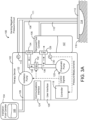
- NPWT system 100 is shown, according to an exemplary embodiment.
- NPWT system 100 is shown to include a therapy device 102 fluidly connected to a wound dressing 112 via tubing 108 and 110.
- Wound dressing 112 may be adhered or sealed to a patient's skin 116 surrounding a wound 114.
- wound dressings 112 which can be used in combination with NPWT system 100 are described in detail in U.S. Patent No. 7,651,484 granted January 26, 2010 , U.S. Patent No. 8,394,081 granted March 12, 2013 , and U.S. Patent Application No. 14/087,418 filed November 22, 2013 .
- the entire disclosure of each of these patents and patent applications is incorporated by reference herein.
- Therapy device 102 can be configured to provide negative pressure wound therapy by reducing the pressure at wound 114.
- Therapy device 102 can draw a vacuum at wound 114 (relative to atmospheric pressure) by removing wound exudate, air, and other fluids from wound 114.
- Wound exudate may include fluid that filters from a patient's circulatory system into lesions or areas of inflammation.
- wound exudate may include water and dissolved solutes such as blood, plasma proteins, white blood cells, platelets, and red blood cells.
- Other fluids removed from wound 114 may include instillation fluid 105 previously delivered to wound 114.
- Instillation fluid 105 can include, for example, a cleansing fluid, a prescribed fluid, a medicated fluid, an antibiotic fluid, or any other type of fluid which can be delivered to wound 114 during wound treatment. Instillation fluid 105 may be held in an instillation fluid canister 104 and controllably dispensed to wound 114 via instillation fluid tubing 108. In some embodiments, instillation fluid canister 104 is detachable from therapy device 102 to allow canister 106 to be refilled and replaced as needed.
- Removed fluid canister 106 may be a component of therapy device 102 configured to collect wound exudate and other fluids 107 removed from wound 114.
- removed fluid canister 106 is detachable from therapy device 102 to allow canister 106 to be emptied and replaced as needed.
- a lower portion of canister 106 may be filled with wound exudate and other fluids 107 removed from wound 114, whereas an upper portion of canister 106 may be filled with air.
- Therapy device 102 can be configured to draw a vacuum within canister 106 by pumping air out of canister 106.
- the reduced pressure within canister 106 can be translated to wound dressing 112 and wound 114 via tubing 110 such that wound dressing 112 and wound 114 are maintained at the same pressure as canister 106.
- Therapy device 102 is shown to include a pneumatic pump 120, an instillation pump 122, a valve 132, a filter 128, and a controller 118.
- Pneumatic pump 120 can be fluidly coupled to removed fluid canister 106 (e.g., via conduit 136) and can be configured to draw a vacuum within canister 106 by pumping air out of canister 106.
- pneumatic pump 120 is configured to operate in both a forward direction and a reverse direction.
- pneumatic pump 120 can operate in the forward direction to pump air out of canister 106 and decrease the pressure within canister 106.
- Pneumatic pump 120 can operate in the reverse direction to pump air into canister 106 and increase the pressure within canister 106.
- Pneumatic pump 120 can be controlled by controller 118, described in greater detail below.
- instillation pump 122 can be fluidly coupled to instillation fluid canister 104 via tubing 109 and fluidly coupled to wound dressing 112 via tubing 108.
- Instillation pump 122 can be operated to deliver instillation fluid 105 to wound dressing 112 and wound 114 by pumping instillation fluid 105 through tubing 109 and tubing 108, as shown in FIG. 4 .
- Instillation pump 122 can be controlled by controller 118, described in greater detail below.
- Filter 128 can be positioned between removed fluid canister 106 and pneumatic pump 120 (e.g., along conduit 136) such that the air pumped out of canister 106 passes through filter 128.
- Filter 128 can be configured to prevent liquid or solid particles from entering conduit 136 and reaching pneumatic pump 120.
- Filter 128 may include, for example, a bacterial filter that is hydrophobic and/or lipophilic such that aqueous and/or oily liquids will bead on the surface of filter 128.
- Pneumatic pump 120 can be configured to provide sufficient airflow through filter 128 that the pressure drop across filter 128 is not substantial (e.g., such that the pressure drop will not substantially interfere with the application of negative pressure to wound 114 from therapy device 102).
- therapy device 102 operates a valve 132 to controllably vent the negative pressure circuit, as shown in FIG. 3A .
- Valve 132 can be fluidly connected with pneumatic pump 120 and filter 128 via conduit 136.
- valve 132 is configured to control airflow between conduit 136 and the environment around therapy device 102.
- valve 132 can be opened to allow airflow into conduit 136 via vent 134 and conduit 138, and closed to prevent airflow into conduit 136 via vent 134 and conduit 138.
- Valve 132 can be opened and closed by controller 118, described in greater detail below.
- pneumatic pump 120 can draw a vacuum within a negative pressure circuit by causing airflow through filter 128 in a first direction, as shown in FIG.
- the negative pressure circuit may include any component of system 100 that can be maintained at a negative pressure when performing negative pressure wound therapy (e.g., conduit 136, removed fluid canister 106, tubing 110, wound dressing 112, and/or wound 114).
- the negative pressure circuit may include conduit 136, removed fluid canister 106, tubing 110, wound dressing 112, and/or wound 114.
- valve 132 When valve 132 is open, airflow from the environment around therapy device 102 may enter conduit 136 via vent 134 and conduit 138 and fill the vacuum within the negative pressure circuit.
- the airflow from conduit 136 into canister 106 and other volumes within the negative pressure circuit may pass through filter 128 in a second direction, opposite the first direction, as shown in FIG. 3A .
- therapy device 102 vents the negative pressure circuit via an orifice 158, as shown in FIG. 3B .
- Orifice 158 may be a small opening in conduit 136 or any other component of the negative pressure circuit (e.g., removed fluid canister 106, tubing 110, tubing 111, wound dressing 112, etc.) and may allow air to leak into the negative pressure circuit at a known rate.
- therapy device 102 vents the negative pressure circuit via orifice 158 rather than operating valve 132. Valve 132 can be omitted from therapy device 102 for any embodiment in which orifice 158 is included.
- the rate at which air leaks into the negative pressure circuit via orifice 158 may be substantially constant or may vary as a function of the negative pressure, depending on the geometry of orifice 158.
- controller 118 can use a stored relationship between negative pressure and leak rate to calculate the leak rate via orifice 158 based measurements of the negative pressure.
- the leakage of air into the negative pressure circuit via orifice 158 can be used to generate a pressure decay curve for use in estimating the volume of wound 114, as described with reference to FIGS. 5-9 .
- therapy device 102 includes a variety of sensors.
- therapy device 102 is shown to include a pressure sensor 130 configured to measure the pressure within canister 106 and/or the pressure at wound dressing 112 or wound 114.
- therapy device 102 includes a pressure sensor 113 configured to measure the pressure within tubing 111.
- Tubing 111 may be connected to wound dressing 112 and may be dedicated to measuring the pressure at wound dressing 112 or wound 114 without having a secondary function such as channeling installation fluid 105 or wound exudate.
- tubing 108, 110, and 111 may be physically separate tubes or separate lumens within a single tube that connects therapy device 102 to wound dressing 112.
- tubing 110 may be described as a negative pressure lumen that functions apply negative pressure wound dressing 112 or wound 114
- tubing 111 may be described as a sensing lumen configured to sense the pressure at wound dressing 112 or wound 114.
- Pressure sensors 130 and 113 can be located within therapy device 102, positioned at any location along tubing 108, 110, and 111, or located at wound dressing 112 in various embodiments. Pressure measurements recorded by pressure sensors 130 and/or 113 can be communicated to controller 118. Controller 118 use the pressure measurements as inputs to various pressure testing operations and control operations performed by controller 118 (described in greater detail with reference to FIGS. 5-12 ).
- Controller 118 can be configured to operate pneumatic pump 120, instillation pump 122, valve 132, and/or other controllable components of therapy device 102.
- controller 118 performs a pressure testing procedure by applying a pressure stimulus to the negative pressure circuit.
- controller 118 may instruct valve 132 to close and operate pneumatic pump 120 to establish negative pressure within the negative pressure circuit.
- controller 118 may deactivate pneumatic pump 120.
- Controller 118 may cause valve 132 to open for a predetermined amount of time and then close after the predetermined amount of time has elapsed.
- Controller 118 may observe a dynamic pressure response of the negative pressure circuit to the pressure stimulus using pressure measurements recorded by pressure sensors 130 and/or 113.
- the dynamic pressure response may be characterized by a variety of parameters including, for example, a depth of purge parameter, a rebound parameter, a delta parameter, and a leak rate parameter (described in greater detail with reference to FIG. 5 ).
- Controller 118 can estimate the volume of wound 114 based on the observed dynamic pressure response. For example, controller 118 can apply the observed parameters as inputs to a pressure model that defines a relationship between the observed parameters and the volume of the negative pressure circuit and/or the volume of wound 114.
- the model may include a polynomial approximation model, a neural network model, or any other model that relates the observed parameters to the volume of the negative pressure circuit and/or the volume of wound 114.
- the pressure model is a pre-existing model stored in controller 118 by the manufacturer of therapy device 102.
- controller 118 can generate the pressure model on-site by performing a training procedure.
- the training procedure may be the same as the pressure testing procedure with the exception that therapy device 102 is connected to a training circuit having a known volume.
- wound dressing 112 can be applied to a test device having a known volume rather than to a patient's skin 116 surrounding wound 114.
- Controller 118 can apply the pressure stimulus to various training circuits having various known volumes and may observe the dynamic pressure response of each training circuit. Each of the known volumes may result in a different dynamic pressure response to the pressure stimulus. Controller 118 can then associate the known volume of each training circuit with the corresponding dynamic pressure response.
- controller 118 uses the dynamic pressure responses of the training circuits to generate the pressure model that defines a relationship between the observed parameters of the dynamic pressure response (e.g., depth of purge, rebound, delta, leak rate, etc.) and the volume of the training circuit.
- the pressure model can then be stored in controller 118 and used to estimate the volume of a wound 114, as previously described.
- controller 118 is configured to execute the pressure testing procedure, observe the dynamic pressure response, and estimate the wound volume at a plurality of times during wound treatment. Controller 118 can then determine healing progression based on changes in the wound volume during wound treatment. In some embodiments, controller 118 is configured to determine a volume of instillation fluid 105 to deliver to wound 114 based on the estimated wound volume. The volume of instillation fluid 105 to deliver may be a predetermined percentage of the volume of wound 114 (e.g., 20%, 50%, 80%, etc.). Controller 118 can then operate instillation pump 122 to deliver the determined volume of instillation fluid 105 to wound 114. These and other features of controller 118 are described in greater detail with reference to FIGS. 5-12 .
- therapy device 102 includes a user interface 126.
- User interface 126 may include one or more buttons, dials, sliders, keys, or other input devices configured to receive input from a user.
- User interface 126 may also include one or more display devices (e.g., LEDs, LCD displays, etc.), speakers, tactile feedback devices, or other output devices configured to provide information to a user.
- the pressure measurements recorded by pressure sensors 130 and/or 113 are presented to a user via user interface 126.
- User interface 126 can also display alerts generated by controller 118. For example, controller 118 can generate a "no canister" alert if canister 106 is not detected.
- therapy device 102 includes a data communications interface 124 (e.g., a USB port, a wireless transceiver, etc.) configured to receive and transmit data.
- Communications interface 124 may include wired or wireless communications interfaces (e.g., jacks, antennas, transmitters, receivers, transceivers, wire terminals, etc.) for conducting data communications external systems or devices.
- the communications may be direct (e.g., local wired or wireless communications) or via a communications network (e.g., a WAN, the Internet, a cellular network, etc.).
- communications interface 124 can include a USB port or an Ethernet card and port for sending and receiving data via an Ethernet-based communications link or network.
- communications interface 124 can include a Wi-Fi transceiver for communicating via a wireless communications network or cellular or mobile phone communications transceivers.
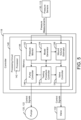
- Controller 118 is shown to include a processing circuit 140 including a processor 142 and memory 144.
- Processor 142 may be a general purpose or specific purpose processor, an application specific integrated circuit (ASIC), one or more field programmable gate arrays (FPGAs), a group of processing components, or other suitable processing components.
- ASIC application specific integrated circuit
- FPGAs field programmable gate arrays
- Processor 142 is configured to execute computer code or instructions stored in memory 144 or received from other computer readable media (e.g., CDROM, network storage, a remote server, etc.).
- Memory 144 may include one or more devices (e.g., memory units, memory devices, storage devices, etc.) for storing data and/or computer code for completing and/or facilitating the various processes described in the present disclosure.
- Memory 144 may include random access memory (RAM), read-only memory (ROM), hard drive storage, temporary storage, non-volatile memory, flash memory, optical memory, or any other suitable memory for storing software objects and/or computer instructions.
- Memory 144 may include database components, object code components, script components, or any other type of information structure for supporting the various activities and information structures described in the present disclosure.
- Memory 144 may be communicably connected to processor 142 via processing circuit 140 and may include computer code for executing (e.g., by processor 142) one or more processes described herein. When processor 142 executes instructions stored in memory 144, processor 142 generally configures controller 118 (and more particularly processing circuit 140) to complete such activities.
- Controller 118 is shown to include a pump controller 146 and a valve controller 150.
- Pump controller 146 can be configured to operate pumps 120 and 122 by generating and providing control signals to pumps 120-122.
- the control signals provided to pumps 120-122 can cause pumps 120-122 to activate, deactivate, or achieve a variable capacity or speed (e.g., operate at half speed, operate at full speed, etc.).
- valve controller 150 can be configured to operate valve 132 by generating and providing control signals to valve 132.
- the control signals provided to valve 132 can cause valve 132 to open, close, or achieve a specified intermediate position (e.g., one-third open, half open, etc.).
- pump controller 146 and valve controller 150 are used by other components of controller 118 (e.g., testing procedure controller 148, wound volume estimator 156, etc.) to operate pumps 120-122 and valve 132 when carrying out the processes described herein.
- pump controller 146 uses input from a canister sensor configured to detect whether removed fluid canister 106 is present.
- Pump controller 146 can be configured to activate pneumatic pump 120 only when removed fluid canister 106 is present. For example, pump controller 146 can check whether canister 106 is present and can activate pneumatic pump 120 in response to a determination that canister 106 is present. However, if canister 106 is not present, pump controller 146 may prevent pneumatic pump 120 from activating.
- pump controller 146 can be configured to activate instillation pump 122 only when instillation fluid canister 104 is present. For example, pump controller 146 can check whether canister 104 is present and can activate instillation pump 122 in response to a determination that canister 104 is present. However, if canister 104 is not present, pump controller 146 may prevent instillation pump 122 from activating.
- Controller 118 is shown to include a pressure monitor 152.
- Pressure monitor 152 can be configured to monitor the pressure within removed fluid canister 106 and/or the pressure within wound dressing 112 or wound 114 using feedback from pressure sensors 130 and/or 113.
- pressure sensors 130 and/or 113 may provide pressure measurements to pressure monitor 152.
- Pressure monitor 152 can use the pressure measurements to determine the pressure within canister 106 and/or the pressure within wound dressing 112 or wound 114 in real-time.
- Pressure monitor 152 can provide the pressure value to model generator 154, pump controller 146, testing procedure controller 148, and/or valve controller 150 for use as an input to control processes performed by such components.
- controller 118 is shown to include a testing procedure controller 148.
- Testing procedure controller 148 can be configured to execute a pressure testing procedure to invoke and observe a dynamic pressure response. If therapy device 102 is connected to a wound dressing 112 applied to a patient's skin 116 over a wound 114, testing procedure controller 148 can observe the dynamic pressure response of a negative pressure circuit that includes conduit 136, removed fluid canister 106, tubing 110, wound dressing 112, and/or wound 114 (which may have an unknown volume).
- testing procedure controller 148 can observe the dynamic pressure response of a training circuit that includes conduit 136, removed fluid canister 106, tubing 110, wound dressing 112, and/or the training device.
- testing procedure controller 148 can be configured to operate pneumatic pump 120 to establish negative pressure within the negative pressure circuit and/or the training circuit.
- the negative pressure may be defined as the difference between the atmospheric pressure surrounding therapy device 102 and the pressure within the negative pressure circuit and/or the training circuit (i.e., the amount by which atmospheric pressure exceeds the pressure within the negative pressure circuit and/or the training circuit).
- the negative pressure is shown having a value of P 0 (e.g., zero mmHg), which indicates that the pressure within the negative pressure circuit and/or the training circuit is equal to atmospheric pressure around therapy device 102.
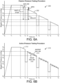
- testing procedure controller 148 begins operating pneumatic pump 120 to reduce the pressure within the negative pressure circuit and/or the training circuit. The negative pressure continues to decrease until it reaches a negative pressure value of P 8 mmHg below atmospheric pressure (e.g., 125 mmHg) at time t 1 . Between time t 1 and time t 2 , testing procedure controller 148 maintains the negative pressure at the value of P 8 by operating pneumatic pump 120 as needed to remove air from the negative pressure circuit and/or the training circuit. Testing procedure controller 148 may then apply a pressure stimulus to the negative pressure circuit and/or the training circuit after the negative pressure has been established within the negative pressure circuit and/or the training circuit.
- P 8 mmHg below atmospheric pressure (e.g., 125 mmHg)
- testing procedure controller 148 deactivates pneumatic pump 120. Beginning at time t 2 , the magnitude of the negative pressure within the negative pressure circuit and/or the training circuit may decrease due to leakage of air into the negative pressure circuit and/or the training circuit while valve 132 is closed. The rate at which the negative pressure decreases while valve 132 is closed is defined by the slope of line 202 between time t 2 and time t 3 . Testing procedure controller 148 may determine the slope of line 202 between time t 2 and time t 3 and may store the slope as the value of the leak rate parameter. The leak rate parameter may be one of the parameters that characterizes the dynamic pressure response of the negative pressure circuit and/or the training circuit.
- testing procedure controller 148 applies a pressure stimulus to the negative pressure circuit and/or the training circuit. Applying the pressure stimulus may include operating valve 132 to controllably vent the negative pressure circuit and/or the training circuit. For example, testing procedure controller 148 may cause valve 132 to open at time t 3 to allow airflow into the negative pressure circuit and/or the training circuit. Testing procedure controller 148 may keep valve 132 open for a predetermined amount of time (i.e., from time t 3 to time t 4 ) and may close valve 132 after closing the valve after the predetermined amount of time has elapsed (i.e., at time t 4 ).
- testing procedure controller 148 may observe the dynamic pressure response of the negative pressure circuit and/or the training circuit to the pressure stimulus.
- the dynamic pressure response may be characterized by several additional parameters including a depth of purge parameter, a rebound parameter, and a delta parameter.
- testing procedure controller 148 applies the pressure stimulus one or more additional times until the negative pressure reaches a threshold value P 1 when valve 132 is closed. Between each application of the pressure stimulus, testing procedure controller 148 may wait for another predetermined amount of time (i.e., from time t 4 to time t 5 and from time t 6 to time t 7 ). For example, testing procedure controller 148 may wait for a predetermined amount of time from time t 4 to time t 5 and may apply the pressure stimulus again at time t 5 . Testing procedure controller 148 may cause valve 132 to open at time t 5 to allow airflow into the negative pressure circuit and/or the training circuit.
- Testing procedure controller 148 may keep valve 132 open for a predetermined amount of time (i.e., from time t 5 to time t 6 ) and may close valve 132 after closing the valve after the predetermined amount of time has elapsed (i.e., at time t 6 ).
- testing procedure controller 148 can be configured to operate pneumatic pump 120 to establish negative pressure within the negative pressure circuit and/or the training circuit.
- the negative pressure may be defined as the difference between the atmospheric pressure surrounding therapy device 102 and the pressure within the negative pressure circuit and/or the training circuit (i.e., the amount by which atmospheric pressure exceeds the pressure within the negative pressure circuit and/or the training circuit).
- the negative pressure is shown having a value of P 0 (e.g., zero mmHg), which indicates that the pressure within the negative pressure circuit and/or the training circuit is equal to atmospheric pressure around therapy device 102.
- the active testing procedure illustrated in FIG. 6B may be substantially similar to the passive testing procedure illustrated in FIG. 6A .
- controller 148 can be configured to operate pneumatic pump 120 using brief controlled activations of pneumatic pump 120 while valve 132 is closed (e.g., between times t 4 and t 5 , between times t 6 and t 7 , and between times t 8 and t 9 ) to compensate for a high leak rate of air into the negative pressure circuit and/or the training circuit.
- line 212 represents the pressure within the negative pressure circuit and/or the training circuit as a function of time.
- the actual leak rate of air into the negative pressure circuit and/or the training circuit while valve 132 is closed is indicated by the slope of line segments 216, whereas the slope of line 214 represents the average or assisted leak rate between times t 4 and t 5 .
- the brief controlled activations of pneumatic pump 120 remove some of the air from the negative pressure circuit and/or the training circuit between times t 4 and t 5 (causing the negative pressure to increase with each controlled activation) such that the average or assisted leak rate is equal to P 6 ⁇ P 5 t 5 ⁇ t 4 .
- Similar negative pressure adjustments can be made between times t 6 and t 7 and between times t 8 and t 9 . In this way, the influx of air into the negative pressure circuit and/or training can be mitigated to compensate for a high actual leak rate while valve 132 is closed.
- graphs 220 and 230 illustrating an uncontrolled testing procedure performed by testing procedure controller 148 is shown, according to an exemplary embodiment.
- the uncontrolled testing procedure does not make use of valve 132 and can be performed for embodiments in which therapy device 102 includes orifice 158 in place of valve 132.
- Graph 220 illustrates the uncontrolled testing procedure when orifice 158 leaks air into the negative pressure circuit and/or training circuit at a variable leak rate, whereas graph 220 illustrates the uncontrolled testing procedure when orifice 158 leaks air into the negative pressure circuit and/or training circuit at a substantially constant leak rate.
- testing procedure controller 148 begins operating pneumatic pump 120 to reduce the pressure within the negative pressure circuit and/or the training circuit.
- the negative pressure continues to decrease until it reaches a negative pressure value of P 2 mmHg below atmospheric pressure (e.g., 125 mmHg) at time t 1 .
- testing procedure controller 148 deactivates pneumatic pump 120.
- the magnitude of the negative pressure within the negative pressure circuit and/or the training circuit may decrease due to leakage of air into the negative pressure circuit and/or the training circuit via orifice 158.
- the rate at which the negative pressure decreases is defined by the slope of line 222 between time t 1 and time t 2 .
- leakage of air into the negative pressure circuit and/or training circuit via orifice 158 occurs more quickly near time t 1 and more slowly near time t 2 , as shown by the slope of line 222 becoming closer to zero as time elapses between t 1 and t 2 .
- testing procedure controller 148 may determine the slope of line 222 at one or more times between time t 1 and time t 2 and may store the slope as the value of the leak rate parameter.
- the leak rate parameter can be defined as the amount of time required for the negative pressure to drop from P 2 to P 1 and can be calculated by subtracting t 1 from t 2 (i.e., t 2 - t 1 ).
- the leak rate parameter may be one of the parameters that characterizes the dynamic pressure response of the negative pressure circuit and/or the training circuit.
- Testing procedure controller 148 can be configured to execute the passive testing procedure, the active testing procedure, and/or the uncontrolled testing procedure in various embodiments.
- the passive testing procedure may be suitable under most conditions and may be the primary or default testing procedure used by testing procedure controller 148.
- the active testing procedure may be suitable in the presence of a high leak rate and may be used by testing procedure controller 148 in response to a determination that the actual leak rate exceeds a predetermined leak rate threshold.
- the uncontrolled testing procedure may be suitable for embodiments in which valve 132 is replaced with orifice 158.
- Leak rate can be determined in a variety of ways.
- leak rate is determined by operating pneumatic pump 120 to achieve a predetermined negative pressure within the negative pressure circuit and measuring the pressure decay over time.
- leak rate is determined based on the effort of pneumatic pump 120 or power consumed by pneumatic pump 120.
- pump controller 146 can be configured to perform brief controlled activations of pneumatic pump 120 to maintain the negative pressure at a setpoint or prevent the negative pressure from dropping at a rate that exceeds a predetermined leak rate threshold, as previously described. The number or frequency of these brief controlled activations of pneumatic pump 120 depends on the leak rate and can be used to determine the leak rate.
- controller 118 can be configured to record the number of brief controlled activations of pneumatic pump 120 within a given time period, measure a frequency or interval of the brief controlled activations, measure a duty cycle of pneumatic pump 120 (e.g., a percentage of time pneumatic pump 120 is active), or measure an amount of power consumed by pneumatic pump 120 to perform the brief controlled activations. Any of these metrics may characterize pump effort and can be stored as a pump effort parameter. Controller 118 can use a stored equation or predetermined relationship to calculate leak rate as a function of the pump effort.
- controller 118 is shown to include a model generator 154.
- Model generator 154 can be configured to generate a model that defines a relationship between the parameters of the dynamic pressure response and the volume of wound 114.
- model generator 154 can cause testing procedure controller 148 to run the pressure testing procedure outlined above for several different training circuits having several different known volumes (e.g., 50 cc, 100 cc, 200 cc, 300 cc, etc.).
- the pressure testing procedure may be referred to as a training procedure.
- Each performance of the training procedure may include applying the pressure stimulus to a training circuit having a known volume, observing the dynamic pressure response of the training circuit to the pressure stimulus, and associating the known volume with the dynamic pressure response of the training circuit.
- model generator 154 records the values of the parameters of the dynamic pressure response (i.e., leak rate, depth of purge, rebound, delta, etc.) for each known volume and associates those values with the known volume.
- the values of the parameters and the known volume form a set of training data which can be used to construct a model.
- the values of the parameters form a set of model input training data, whereas the known volumes form a set of model output training data.
- Model generator 154 can use any of a variety of model generation techniques to construct a model (i.e., a mathematical model) that relates the values of the parameters to the corresponding volume in the set of training data.
- model generator 154 creates a polynomial approximation model to relate the values of the parameters to the corresponding volume.
- model generator 154 can perform a curve fitting process such as polynomial regression using any of a variety of regression techniques. Examples of regression techniques which can be used by model generator 154 include least squares, ordinary least squares, linear least squares, partial least squares, total least squares, generalized least squares, weighted least squares non-linear least squares, non-negative least squares, iteratively reweighted least squares, ridge regression, least absolute deviations, Bayesian linear regression, Bayesian multivariate linear regression, etc.
- model generator 154 creates a neural network model to relate the values of the parameters to the corresponding volume.
- model generator 154 can perform a machine learning process. Examples of machine learning techniques which can be used by model generator 154 include decision tree learning, association rule learning, artificial neural networks, deep learning, inductive logic programming, support vector machines, clustering, Bayesian networks, reinforcement learning, representation learning, similarity and metric learning, sparse dictionary learning, genetic algorithms, rule-based machine learning, etc.
- Each of pressure decay curves 252-258 corresponds to a known volume and represents the pressure within the negative pressure circuit and/or the training circuit as a function of time for the corresponding volume.
- pressure decay curve 252 corresponds to a volume of 300 cc
- pressure decay curve 254 corresponds to a volume of 200 cc
- pressure decay curve 256 corresponds to a volume of 100 cc
- pressure decay curve 258 corresponds to a volume of 50 cc.
- Each of pressure decay curves 252-258 may be created by model generator 154 using any of the modeling techniques described above.
- pressure decay curves 252-258 can be created by running the pressure testing procedure for each known volume and plotting the pressure decay over time for each known volume.
- controller 118 uses pressure decay curves 252-258 to translate a measured pressure value into a corresponding volume when estimating the volume of wound 114.
- controller 118 can measure the pressure of the negative pressure circuit and identify a time at which the pressure was measured.
- Controller 118 can interpolate between pressure decay curves 252-258 to determine an interpolated pressure value that corresponds to the measured pressure and time pair. For example, at time t 1 , controller 118 may observe a pressure value of P 1 .
- the combination of time t 1 and pressure P 1 defines a point 260 in graph 250. Point 260 lies approximately halfway between pressure decay curve 252 and pressure decay curve 254.
- Controller 118 can interpolate between pressure decay curves 252 and 254 to estimate that the volume of the negative pressure circuit is approximately halfway between the known volumes corresponding to pressure decay curves 252 and 254 (i.e., approximately 250 cc). In other embodiments, controller 118 estimates the volume of wound 114 by applying observed parameters of a dynamic pressure response as inputs to a pressure model.
- FIG. 7B a graph 260 illustrating an unassisted pressure decay curve 264 and an assisted pressure decay curve 262 is shown, according to an exemplary embodiment.
- both unassisted pressure decay curve 264 and assisted pressure decay curve 262 correspond to the same volume of the negative pressure circuit and/or training circuit.
- Unassisted pressure decay curve 264 illustrates the pressure decay during the passive testing procedure shown in FIG. 6A (i.e., when pneumatic pump 120 is not operated to compensate for a high leak rate).
- assisted pressure decay curve 262 illustrates the pressure decay during the active testing procedure (i.e., when pneumatic pump 120 is operated to compensate for a high leak rate).
- operating pneumatic pump 120 during the active testing procedure mitigates the pressure decay and therefore results in a more gradual assisted pressure decay curve 262 relative to unassisted pressure decay curve 264.
- controller 118 is shown to include a wound volume estimator 156.
- Wound volume estimator 156 can be configured to estimate the volume of wound 114 based on pressure measurements collected by pressure sensors 130 and/or 113.
- wound volume estimator 156 estimates the volume of wound 114 by performing a pressure testing procedure.
- the pressure testing procedure may include applying a pressure stimulus to the negative pressure circuit and observing the dynamic pressure response of the negative pressure circuit to the pressure stimulus.
- the negative pressure circuit may include any component of system 100 that can be maintained at a negative pressure when performing negative pressure wound therapy (e.g., conduit 136, removed fluid canister 106, tubing 110, wound dressing 112, and/or wound 114).
- wound volume estimator 156 may instruct valve 132 to close and operate pneumatic pump 120 to establish negative pressure within the negative pressure circuit. Once the negative pressure has been established, wound volume estimator 156 may deactivate pneumatic pump 120. Wound volume estimator 156 may cause valve 132 to open for a predetermined amount of time and then close after the predetermined amount of time has elapsed. Wound volume estimator 156 may observe a dynamic pressure response of the negative pressure circuit to the pressure stimulus using pressure measurements recorded by pressure sensors 130 and/or 113. The dynamic pressure response may be characterized by a variety of parameters including, for example, a depth of purge parameter, a rebound parameter, a delta parameter, and a leak rate parameter, as previously described.
- Wound volume estimator 156 can estimate the volume of wound 114 based on the observed dynamic pressure response. For example, wound volume estimator 156 can apply the observed parameters as inputs to a pressure model that defines a relationship between the observed parameters and the volume of the negative pressure circuit and/or the volume of wound 114.
- the pressure model is the model created by model generator 154 (e.g., by performing the training procedure based on training data collected using the training circuits).
- the model may include a polynomial approximation model, a neural network model, or any other model that relates the observed parameters to the volume of the negative pressure circuit and/or the volume of wound 114.
- the pressure model is a pre-existing model stored in memory 144 by the manufacturer of therapy device 102.
- wound volume estimator 156 is configured to execute the pressure testing procedure, observe the dynamic pressure response, and estimate the wound volume at a plurality of times during wound treatment. Wound volume estimator 156 can then determine healing progression based on changes in the wound volume during wound treatment. In some embodiments, wound volume estimator 156 is configured to determine a volume of instillation fluid 105 to deliver to wound 114 based on the estimated wound volume. The volume of instillation fluid 105 to deliver may be a predetermined percentage of the volume of wound 114 (e.g., 20%, 50%, 80%, etc.). Wound volume estimator 156 can then operate instillation pump 122 to deliver the determined volume of instillation fluid 105 to wound 114.
- Process 300 can be performed by one or more components of therapy device 102 to create a model that characterizes the dynamic pressure response of a training circuit and/or negative pressure circuit.
- process 300 can be performed by controller 118, pneumatic pump 120, valve 132, and/or pressure sensors 130 and/or 113.
- process 300 is executed by testing procedure controller 148 and model generator 154.
- Process 300 is shown to include applying a pressure stimulus to a training circuit having a known volume (step 302).
- the training circuit may include one or more components of therapy device 102 (e.g., conduit 136, removed fluid canister 106, etc.) and/or other components of system 100 (e.g., tubing 110, wound dressing 112). Under wound treatment conditions, wound dressing 112 would normally be applied to a patient's skin 116 surrounding a wound 114. However, the training circuit may replace wound 114 with a training device having a known volume.
- Step 302 may include instructing valve 132 to close and operating pneumatic pump 120 to establish negative pressure within the training circuit. Once the negative pressure has been established, pneumatic pump 120 may be deactivated.
- Step 302 may include causing valve 132 to open for a predetermined amount of time and then closing valve 132 after the predetermined amount of time has elapsed.
- Process 300 is shown to include observing the dynamic pressure response of the training circuit to the pressure stimulus (step 304) and associating the known volume of the training circuit with the dynamic pressure response (step 306).
- Step 304 may include monitoring the pressure of the training circuit over time using pressure measurements recorded by pressure sensors 130 and/or 113.
- the dynamic pressure response may be characterized by a variety of parameters including, for example, a depth of purge parameter, a rebound parameter, a delta parameter, and a leak rate parameter, as previously described.
- Step 306 may include storing the values of the parameters of the dynamic pressure response as input training data and storing the known volume of the training circuit as output training data that corresponds to the input training data.
- Process 300 is shown to include determining whether all volumes have been tested (step 308). If not all volumes have been tested (i.e., the result of step 308 is "no"), the training device to which therapy device 102 is connected can be replaced with a different training device having a different known volume. Steps 302-306 can then be repeated to apply the pressure stimulus to apply the pressure stimulus and observe the dynamic pressure response of the training circuit for each known volume. Each set of dynamic pressure response parameters can be stored as input training data and each set and the corresponding known volume can be stored as output training data.
- Step 310 may include using any of a variety of model generation techniques to construct a model (i.e., a mathematical model) that relates the values of the dynamic pressure response parameters to the corresponding volume in the set of training data.
- the model generated in step 310 is a polynomial approximation model.
- Step 310 may include performing a curve fitting process such as polynomial regression using any of a variety of regression techniques.
- regression techniques which can be used in step 310 include least squares, ordinary least squares, linear least squares, partial least squares, total least squares, generalized least squares, weighted least squares non-linear least squares, non-negative least squares, iteratively reweighted least squares, ridge regression, least absolute deviations, Bayesian linear regression, Bayesian multivariate linear regression, etc.
- the model generated in step 310 is a neural network model.
- Step 310 may include using any of a variety of machine learning techniques to generate a neural network model that relates the values of the dynamic pressure response parameters to the corresponding volume in the set of training data.
- machine learning techniques which can be used in step 310 include decision tree learning, association rule learning, artificial neural networks, deep learning, inductive logic programming, support vector machines, clustering, Bayesian networks, reinforcement learning, representation learning, similarity and metric learning, sparse dictionary learning, genetic algorithms, rule-based machine learning, etc.
- the pressure model can then be stored for use in estimating the volume of wound 114.
- Process 400 can be performed by one or more components of therapy device 102 estimate the volume of wound 114.
- process 400 can be performed by controller 118, pneumatic pump 120, valve 132, and/or pressure sensors 130 and/or 113.
- process 400 is executed by testing procedure controller 148 and wound volume estimator 156.
- Process 400 is shown to include applying a pressure stimulus to a negative pressure circuit having an unknown volume (step 402).
- the negative pressure circuit may include one or more components of therapy device 102 (e.g., conduit 136, removed fluid canister 106, etc.) and/or other components of system 100 (e.g., tubing 110, wound dressing 112, wound 114). Under wound treatment conditions, wound dressing 112 may be applied to a patient's skin 116 surrounding wound 114. Accordingly, the volume of wound 114 forms part of the negative pressure circuit.
- Step 402 may include instructing valve 132 to close and operating pneumatic pump 120 to establish negative pressure within the negative pressure circuit. Once the negative pressure has been established, pneumatic pump 120 may be deactivated.
- Step 402 may include causing valve 132 to open for a predetermined amount of time and then closing valve 132 after the predetermined amount of time has elapsed.
- step 402 includes executing the passive testing procedure and/or the active testing procedure, as described with reference to FIGS. 6A-6B .
- Process 400 is shown to include observing the dynamic pressure response of the negative pressure circuit to the pressure stimulus (step 404) and determining values for parameters that characterize the dynamic pressure response (step 406).
- Step 404 may include monitoring the pressure of the negative pressure circuit over time using pressure measurements recorded by pressure sensors 130 and/or 113.
- the dynamic pressure response may be characterized by a variety of parameters including, for example, a depth of purge parameter, a rebound parameter, a delta parameter, and a leak rate parameter, as previously described.
- Step 406 may include storing the values of the parameters of the dynamic pressure response.
- Process 400 is shown to include applying the values of the parameters as inputs to a pressure response model that defines a wound volume as a function of the parameters (step 408).
- the pressure response model is the model created by performing process 300 (e.g., by performing a regression process or machine learning process using training data collected using the training circuits).
- the model may include a polynomial approximation model, a neural network model, or any other model that relates the observed parameters to the volume of the negative pressure circuit and/or the volume of wound 114.
- Process 400 is shown to include estimating the volume of the wound based on an output of the model (step 410).
- the output of the pressure response model is the estimated volume of wound 114. Accordingly, the output of the pressure response model can be used as the estimated wound volume.
- the output of the pressure response model is the estimated volume of the negative pressure circuit.
- step 410 may include subtracting known volumes of other components of the negative pressure circuit to isolate the estimated volume of wound 114. For example, step 410 may include subtracting the known volumes of conduit 136, removed fluid canister 106, tubing 110, and/or wound dressing 112 such that the only volume remaining is the volume of wound 114.
- the volume of removed fluid canister 106 that forms part of the negative pressure circuit is limited to the volume of the air within canister 106.
- the volume of the air within canister 106 may vary based on the level of removed fluid 107 within canister 106.
- removed fluid canister 106 includes a sensor (e.g., a level sensor, a weight sensor, etc.) that operates to record the level of removed fluid 107 within canister 106. The observed level of removed fluid 107 can then be used to estimate the air volume within canister 106.
- the volume of air within canister 106 can be estimated by performing a dead-space detection process.
- Process 500 can be performed by one or more components of therapy device 102 to assess healing progression based on the volume of wound 114.
- process 500 can be performed by controller 118, pneumatic pump 120, valve 132, and/or pressure sensors 130 and/or 113.
- Process 500 is shown to include executing a pressure testing procedure to estimate wound volume at a plurality of times during wound treatment (step 502).
- Step 502 may include performing process 400 multiple times during wound treatment (e.g., once per day).
- Each time process 400 is performed the volume of wound 114 may be estimated.
- Each estimate of the wound volume can be stored along with the time at which the estimate was obtained.
- the pairs of time and estimated wound volume can be stored as data points within the memory of therapy device 102 and/or presented to a user as an output of therapy device 102 (e.g., via communications interface 124 or user interface 126).
- the estimated wound volume can be plotted as a function of time, as shown in FIG. 11 .
- Process 500 is shown to include determining healing progression based on changes in the wound volume during wound treatment (step 504).
- Step 504 may include comparing a current estimate of the wound volume to one or more previous estimates of the wound volume to identify a change in the wound volume.
- step 504 includes determining a rate at which wound 114 is healing based on the changes in the wound volume over time.
- step 504 includes extrapolating or predicting a time at which wound 114 will be fully healed based on a series of wound volume estimates.
- step 504 may include predicting a time at which the estimated wound volume will reach zero (or another threshold value) based on the series of wound volume estimates obtained in step 502.
- Controller 118 can use the estimated wound volume to calculate a volume of instillation fluid 105 to deliver to wound 114 (step 702). In some embodiments, controller 118 calculates the volume of instillation fluid 105 to deliver to wound 114 by multiplying the estimated wound volume by a fluid instillation factor.
- the fluid instillation factor may be less than one (i.e., between zero and one) such that the calculated volume of instillation fluid 105 is less than the volume of wound 114. In some embodiments, the fluid instillation factor is between approximately 0.2 and approximately 0.8. However, it is contemplated that the fluid instillation factor can have any value in various alternative embodiments.
- line 602 represents the estimated volume of wound 114 as a function of time
- line 604 represents the calculated volume of instillation fluid 105 to deliver to wound 114 over time.
- the estimated volume of wound 114 is V 4 .
- the estimated volume of wound 114 decreases and reaches a value of V 2 at time t 2 .
- Controller 118 can then operate a pump to deliver the calculated volume of instillation fluid 105 to wound 114 (step 704).
- Step 704 can include operating instillation pump 122 to draw instillation fluid 105 from instillation fluid canister 104 and deliver instillation fluid 105 to wound 114 via tubing 109 and 108.
- the calculated volume of instillation fluid 105 is also used to control the operation of pneumatic pump 120.
- controller 118 can operate pneumatic pump 120 to remove the volume of instillation fluid 105 from wound 114 via tubing 110.
- the amount of time that pneumatic pump 120 operates may be a function of the volume of instillation fluid 105 that was delivered to wound 114.
- FIG. 13 a graph 800 illustrating several stages of a wound therapy process is shown, according to an exemplary embodiment.
- the wound therapy process illustrated in FIG. 13 can be performed by one or more components of therapy device 102 as previously described.
- Line 802 represents the negative pressure within the negative pressure circuit at each stage of the wound therapy process.
- therapy device 102 begins operating pneumatic pump 120 to reduce the negative pressure within the negative pressure circuit during an initial draw down stage 804 that occurs between time t 0 and t 1 .
- the negative pressure within the negative pressure circuit reaches approximately 125 mmHg below atmospheric pressure and pneumatic pump 120 is deactivated.
- negative pressure within the negative pressure circuit is monitored using measurements from pressure sensors 130 and/or 113 during a seal check stage 806.
- a substantial change in the pressure between times t 1 and t 2 may indicate that the seal between wound dressing 112 and the patient's skin is not airtight whereas a substantially constant pressure between times t 1 and t 2 may indicate that wound dressing 112 is properly sealed to the patient's skin.
- pneumatic pump 120 is activated until the negative pressure within the negative pressure circuit is reduced to approximately 200 mmHg below atmospheric pressure. Upon reaching a negative pressure of 200 mmHg, pneumatic pump 120 is deactivated and a wound volume determination stage 808 is initiated. Pneumatic pump 120 may be intermittently activated during stage 808 to maintain the negative pressure at approximately 200 mmHg and compensate for any leakage of air into the negative pressure circuit.
- pneumatic pump 120 is deactivated and a leak determination stage 810 begins. Between times t 3 and t 4 , the negative pressure within the negative pressure circuit is monitored to determine a rate at which air leaks into the negative pressure circuit. At time t 4 , pneumatic pump 120 is reactivated to reduce the negative pressure back to approximately 200 mmHg. Pneumatic pump 120 may be intermittently activated between time t 4 and t 5 to maintain the negative pressure at approximately 200 mmHg and compensate for any leakage of air into the negative pressure circuit.
- pneumatic pump 120 is deactivated and a wound volume determination stage 812 begins.
- therapy device 102 may perform one or more of the pressure testing procedures described with reference to FIGS. 6A-6D .
- the time ranges shown in graphs 200, 210, 220, and 230 may occur entirely between times t 5 and t 6 in graph 800.
- pneumatic pump 120 is activated and the negative pressure is reduced to approximately 125 mmHg below atmospheric pressure during a draw down for instillation stage 814.
- pneumatic pump 120 is deactivated.
- Pneumatic pump 120 may be intermittently activated between times t 7 and t 8 to maintain the negative pressure at approximately 125 mmHg and compensate for any leakage of air into the negative pressure circuit.
- instillation fluid 105 may be delivered to wound 114.
- the present disclosure contemplates methods, systems and program products on any machine-readable media for accomplishing various operations.
- the embodiments of the present disclosure can be implemented using existing computer processors, or by a special purpose computer processor for an appropriate system, incorporated for this or another purpose, or by a hardwired system.
- Embodiments within the scope of the present disclosure include program products comprising machine-readable media for carrying or having machine-executable instructions or data structures stored thereon.
- Such machine-readable media can be any available media that can be accessed by a general purpose or special purpose computer or other machine with a processor.
- machine-readable media can comprise RAM, ROM, EPROM, EEPROM, CD-ROM or other optical disk storage, magnetic disk storage or other magnetic storage devices, or any other medium which can be used to carry or store desired program code in the form of machine-executable instructions or data structures and which can be accessed by a general purpose or special purpose computer or other machine with a processor. Combinations of the above are also included within the scope of machine-readable media.
- Machine-executable instructions include, for example, instructions and data which cause a general purpose computer, special purpose computer, or special purpose processing machines to perform a certain function or group of functions.
Applications Claiming Priority (4)
| Application Number | Priority Date | Filing Date | Title |
|---|---|---|---|
| US201862650132P | 2018-03-29 | 2018-03-29 | |
| US201962799241P | 2019-01-31 | 2019-01-31 | |
| PCT/US2019/023904 WO2019190993A1 (en) | 2018-03-29 | 2019-03-25 | Wound therapy system with wound volume estimation |
| EP19716660.6A EP3773777B1 (de) | 2018-03-29 | 2019-03-25 | Wundtherapiesystem mit wundvolumenschätzung |
Related Parent Applications (1)
| Application Number | Title | Priority Date | Filing Date |
|---|---|---|---|
| EP19716660.6A Division EP3773777B1 (de) | 2018-03-29 | 2019-03-25 | Wundtherapiesystem mit wundvolumenschätzung |
Publications (2)
| Publication Number | Publication Date |
|---|---|
| EP4331481A2 true EP4331481A2 (de) | 2024-03-06 |
| EP4331481A3 EP4331481A3 (de) | 2024-04-03 |
Family
ID=66102237
Family Applications (2)
| Application Number | Title | Priority Date | Filing Date |
|---|---|---|---|
| EP24151949.5A Pending EP4331481A3 (de) | 2018-03-29 | 2019-03-25 | Wundtherapiesystem mit wundvolumenschätzung |
| EP19716660.6A Active EP3773777B1 (de) | 2018-03-29 | 2019-03-25 | Wundtherapiesystem mit wundvolumenschätzung |
Family Applications After (1)
| Application Number | Title | Priority Date | Filing Date |
|---|---|---|---|
| EP19716660.6A Active EP3773777B1 (de) | 2018-03-29 | 2019-03-25 | Wundtherapiesystem mit wundvolumenschätzung |
Country Status (5)
| Country | Link |
|---|---|
| US (3) | US20210077671A1 (de) |
| EP (2) | EP4331481A3 (de) |
| JP (2) | JP7331002B2 (de) |
| CN (1) | CN111936177A (de) |
| WO (1) | WO2019190993A1 (de) |
Families Citing this family (23)
| Publication number | Priority date | Publication date | Assignee | Title |
|---|---|---|---|---|
| GB0808376D0 (en) | 2008-05-08 | 2008-06-18 | Bristol Myers Squibb Co | Wound dressing |
| GB0817796D0 (en) | 2008-09-29 | 2008-11-05 | Convatec Inc | wound dressing |
| GB201020236D0 (en) | 2010-11-30 | 2011-01-12 | Convatec Technologies Inc | A composition for detecting biofilms on viable tissues |
| CN103347562B (zh) | 2010-12-08 | 2016-08-10 | 康沃特克科技公司 | 伤口分泌液系统附件 |
| WO2012078781A1 (en) | 2010-12-08 | 2012-06-14 | Convatec Technologies Inc. | Integrated system for assessing wound exudates |
| GB201115182D0 (en) | 2011-09-02 | 2011-10-19 | Trio Healthcare Ltd | Skin contact material |
| GB2497406A (en) | 2011-11-29 | 2013-06-12 | Webtec Converting Llc | Dressing with a perforated binder layer |
| US20150354096A1 (en) | 2012-12-20 | 2015-12-10 | Convatec Technologies Inc. | Processing of chemically modified cellulosic fibres |
| CN109310528B (zh) | 2016-03-30 | 2021-07-20 | 康沃特克科技公司 | 检测伤口中的微生物感染 |
| US11740241B2 (en) | 2016-03-30 | 2023-08-29 | Synovo Gmbh | Construct including an anchor, an enzyme recognition site and an indicator region for detecting microbial infection in wounds |
| JP7071957B2 (ja) | 2016-07-08 | 2022-05-19 | コンバテック・テクノロジーズ・インコーポレイテッド | 可撓性陰圧システム |
| CA3030151A1 (en) | 2016-07-08 | 2018-01-11 | Convatec Technologies Inc. | Fluid collection apparatus |
| CA3030153C (en) | 2016-07-08 | 2023-10-24 | Convatec Technologies Inc. | Fluid flow sensing |
| CN111936177A (zh) * | 2018-03-29 | 2020-11-13 | 凯希特许有限公司 | 具有伤口体积估计的伤口疗法系统 |
| US11701264B2 (en) | 2018-06-27 | 2023-07-18 | Kci Licensing, Inc. | Wound therapy system with wound volume estimation using geometric approximation |
| US20210316060A1 (en) * | 2018-12-29 | 2021-10-14 | Tienan LIU | Medical drainage monitoring method, apparatus, and system based on image recognition |
| USD903093S1 (en) * | 2019-03-08 | 2020-11-24 | Kci Licensing, Inc. | Negative-pressure therapy device module |
| CN113573748A (zh) * | 2019-03-27 | 2021-10-29 | 凯希特许有限公司 | 具有伤口体积估计的伤口治疗系统 |
| US11426506B2 (en) | 2019-03-27 | 2022-08-30 | Kci Licensing, Inc. | Wound therapy system with wound volume estimation |
| US11331221B2 (en) | 2019-12-27 | 2022-05-17 | Convatec Limited | Negative pressure wound dressing |
| US11771819B2 (en) | 2019-12-27 | 2023-10-03 | Convatec Limited | Low profile filter devices suitable for use in negative pressure wound therapy systems |
| US20240009377A1 (en) * | 2020-01-29 | 2024-01-11 | Kci Licensing, Inc. | Wound therapy system with in-line orifice |
| GB202001212D0 (en) * | 2020-01-29 | 2020-03-11 | Smith & Nephew | Systems and methods for measuring and tracking wound volume |
Citations (2)
| Publication number | Priority date | Publication date | Assignee | Title |
|---|---|---|---|---|
| US7651484B2 (en) | 2006-02-06 | 2010-01-26 | Kci Licensing, Inc. | Systems and methods for improved connection to wound dressings in conjunction with reduced pressure wound treatment systems |
| US8394081B2 (en) | 2010-01-29 | 2013-03-12 | Kci Licensing, Inc. | Wound treatment apparatuses and methods for controlled delivery of fluids to a wound |
Family Cites Families (162)
| Publication number | Priority date | Publication date | Assignee | Title |
|---|---|---|---|---|
| US1355846A (en) | 1920-02-06 | 1920-10-19 | David A Rannells | Medical appliance |
| US2547758A (en) | 1949-01-05 | 1951-04-03 | Wilmer B Keeling | Instrument for treating the male urethra |
| US2632443A (en) | 1949-04-18 | 1953-03-24 | Eleanor P Lesher | Surgical dressing |
| GB692578A (en) | 1949-09-13 | 1953-06-10 | Minnesota Mining & Mfg | Improvements in or relating to drape sheets for surgical use |
| US2682873A (en) | 1952-07-30 | 1954-07-06 | Johnson & Johnson | General purpose protective dressing |
| NL189176B (nl) | 1956-07-13 | 1900-01-01 | Hisamitsu Pharmaceutical Co | Pleister op basis van een synthetische rubber. |
| US2969057A (en) | 1957-11-04 | 1961-01-24 | Brady Co W H | Nematodic swab |
| US3066672A (en) | 1960-09-27 | 1962-12-04 | Jr William H Crosby | Method and apparatus for serial sampling of intestinal juice |
| US3367332A (en) | 1965-08-27 | 1968-02-06 | Gen Electric | Product and process for establishing a sterile area of skin |
| US3520300A (en) | 1967-03-15 | 1970-07-14 | Amp Inc | Surgical sponge and suction device |
| US3568675A (en) | 1968-08-30 | 1971-03-09 | Clyde B Harvey | Fistula and penetrating wound dressing |
| US3682180A (en) | 1970-06-08 | 1972-08-08 | Coilform Co Inc | Drain clip for surgical drain |
| BE789293Q (fr) | 1970-12-07 | 1973-01-15 | Parke Davis & Co | Pansement medico-chirugical pour brulures et lesions analogues |
| US3826254A (en) | 1973-02-26 | 1974-07-30 | Verco Ind | Needle or catheter retaining appliance |
| DE2527706A1 (de) | 1975-06-21 | 1976-12-30 | Hanfried Dr Med Weigand | Einrichtung zum einleiten von kontrastmittel in einen kuenstlichen darmausgang |
| DE2640413C3 (de) | 1976-09-08 | 1980-03-27 | Richard Wolf Gmbh, 7134 Knittlingen | Katheter-Überwachungsgerät |
| NL7710909A (nl) | 1976-10-08 | 1978-04-11 | Smith & Nephew | Samengestelde hechtstrook. |
| GB1562244A (en) | 1976-11-11 | 1980-03-05 | Lock P M | Wound dressing materials |
| US4080970A (en) | 1976-11-17 | 1978-03-28 | Miller Thomas J | Post-operative combination dressing and internal drain tube with external shield and tube connector |
| US4139004A (en) | 1977-02-17 | 1979-02-13 | Gonzalez Jr Harry | Bandage apparatus for treating burns |
| US4184510A (en) | 1977-03-15 | 1980-01-22 | Fibra-Sonics, Inc. | Valued device for controlling vacuum in surgery |
| US4165748A (en) | 1977-11-07 | 1979-08-28 | Johnson Melissa C | Catheter tube holder |
| US4256109A (en) | 1978-07-10 | 1981-03-17 | Nichols Robert L | Shut off valve for medical suction apparatus |
| SE414994B (sv) | 1978-11-28 | 1980-09-01 | Landstingens Inkopscentral | Venkateterforband |
| BR7908937A (pt) | 1978-12-06 | 1981-06-30 | Svedman Paul | Dispositivo para tratamento de tecidos,por exemplo,pele |
| US4266545A (en) | 1979-04-06 | 1981-05-12 | Moss James P | Portable suction device for collecting fluids from a closed wound |
| US4284079A (en) | 1979-06-28 | 1981-08-18 | Adair Edwin Lloyd | Method for applying a male incontinence device |
| US4261363A (en) | 1979-11-09 | 1981-04-14 | C. R. Bard, Inc. | Retention clips for body fluid drains |
| US4569348A (en) | 1980-02-22 | 1986-02-11 | Velcro Usa Inc. | Catheter tube holder strap |
| ATE14835T1 (de) | 1980-03-11 | 1985-08-15 | Schmid Eduard | Hauttransplantations-druckverband. |
| US4297995A (en) | 1980-06-03 | 1981-11-03 | Key Pharmaceuticals, Inc. | Bandage containing attachment post |
| US4333468A (en) | 1980-08-18 | 1982-06-08 | Geist Robert W | Mesentery tube holder apparatus |
| US4465485A (en) | 1981-03-06 | 1984-08-14 | Becton, Dickinson And Company | Suction canister with unitary shut-off valve and filter features |
| US4392853A (en) | 1981-03-16 | 1983-07-12 | Rudolph Muto | Sterile assembly for protecting and fastening an indwelling device |
| US4373519A (en) | 1981-06-26 | 1983-02-15 | Minnesota Mining And Manufacturing Company | Composite wound dressing |
| US4392858A (en) | 1981-07-16 | 1983-07-12 | Sherwood Medical Company | Wound drainage device |
| US4419097A (en) | 1981-07-31 | 1983-12-06 | Rexar Industries, Inc. | Attachment for catheter tube |
| AU550575B2 (en) | 1981-08-07 | 1986-03-27 | Richard Christian Wright | Wound drainage device |
| SE429197B (sv) | 1981-10-14 | 1983-08-22 | Frese Nielsen | Anordning for behandling av sar |
| DE3146266A1 (de) | 1981-11-21 | 1983-06-01 | B. Braun Melsungen Ag, 3508 Melsungen | Kombinierte vorrichtung fuer eine medizinische saugdrainage |
| US4551139A (en) | 1982-02-08 | 1985-11-05 | Marion Laboratories, Inc. | Method and apparatus for burn wound treatment |
| US4475909A (en) | 1982-05-06 | 1984-10-09 | Eisenberg Melvin I | Male urinary device and method for applying the device |
| EP0100148B1 (de) | 1982-07-06 | 1986-01-08 | Dow Corning Limited | Medizinischer chirurgischer Wundverband und Verfahren zu seiner Herstellung |
| NZ206837A (en) | 1983-01-27 | 1986-08-08 | Johnson & Johnson Prod Inc | Thin film adhesive dressing:backing material in three sections |
| US4548202A (en) | 1983-06-20 | 1985-10-22 | Ethicon, Inc. | Mesh tissue fasteners |
| US4540412A (en) | 1983-07-14 | 1985-09-10 | The Kendall Company | Device for moist heat therapy |
| US4543100A (en) | 1983-11-01 | 1985-09-24 | Brodsky Stuart A | Catheter and drain tube retainer |
| US4525374A (en) | 1984-02-27 | 1985-06-25 | Manresa, Inc. | Treating hydrophobic filters to render them hydrophilic |
| GB2157958A (en) | 1984-05-03 | 1985-11-06 | Ernest Edward Austen Bedding | Ball game net support |
| US4897081A (en) | 1984-05-25 | 1990-01-30 | Thermedics Inc. | Percutaneous access device |
| US5215522A (en) | 1984-07-23 | 1993-06-01 | Ballard Medical Products | Single use medical aspirating device and method |
| GB8419745D0 (en) | 1984-08-02 | 1984-09-05 | Smith & Nephew Ass | Wound dressing |
| US4872450A (en) | 1984-08-17 | 1989-10-10 | Austad Eric D | Wound dressing and method of forming same |
| US4655754A (en) | 1984-11-09 | 1987-04-07 | Stryker Corporation | Vacuum wound drainage system and lipids baffle therefor |
| US4826494A (en) | 1984-11-09 | 1989-05-02 | Stryker Corporation | Vacuum wound drainage system |
| US4605399A (en) | 1984-12-04 | 1986-08-12 | Complex, Inc. | Transdermal infusion device |
| US5037397A (en) | 1985-05-03 | 1991-08-06 | Medical Distributors, Inc. | Universal clamp |
| US4640688A (en) | 1985-08-23 | 1987-02-03 | Mentor Corporation | Urine collection catheter |
| US4710165A (en) | 1985-09-16 | 1987-12-01 | Mcneil Charles B | Wearable, variable rate suction/collection device |
| US4758220A (en) | 1985-09-26 | 1988-07-19 | Alcon Laboratories, Inc. | Surgical cassette proximity sensing and latching apparatus |
| US4733659A (en) | 1986-01-17 | 1988-03-29 | Seton Company | Foam bandage |
| EP0256060A1 (de) | 1986-01-31 | 1988-02-24 | OSMOND, Roger L. W. | Absaugungssystem für wund-, magen- und darmdrainage |
| US4838883A (en) | 1986-03-07 | 1989-06-13 | Nissho Corporation | Urine-collecting device |
| JPS62281965A (ja) | 1986-05-29 | 1987-12-07 | テルモ株式会社 | カテ−テルおよびカテ−テル用固定部材 |
| GB8621884D0 (en) | 1986-09-11 | 1986-10-15 | Bard Ltd | Catheter applicator |
| GB2195255B (en) | 1986-09-30 | 1991-05-01 | Vacutec Uk Limited | Apparatus for vacuum treatment of an epidermal surface |
| US4743232A (en) | 1986-10-06 | 1988-05-10 | The Clinipad Corporation | Package assembly for plastic film bandage |
| DE3634569A1 (de) | 1986-10-10 | 1988-04-21 | Sachse Hans E | Kondomkatheter, ein harnroehrenkatheter zur verhinderung von aufsteigenden infektionen |
| JPS63135179A (ja) | 1986-11-26 | 1988-06-07 | 立花 俊郎 | 薬物の経皮投与具 |
| GB8628564D0 (en) | 1986-11-28 | 1987-01-07 | Smiths Industries Plc | Anti-foaming agent suction apparatus |
| GB8706116D0 (en) | 1987-03-14 | 1987-04-15 | Smith & Nephew Ass | Adhesive dressings |
| US4787888A (en) | 1987-06-01 | 1988-11-29 | University Of Connecticut | Disposable piezoelectric polymer bandage for percutaneous delivery of drugs and method for such percutaneous delivery (a) |
| US4863449A (en) | 1987-07-06 | 1989-09-05 | Hollister Incorporated | Adhesive-lined elastic condom cathether |
| US5176663A (en) | 1987-12-02 | 1993-01-05 | Pal Svedman | Dressing having pad with compressibility limiting elements |
| US4906240A (en) | 1988-02-01 | 1990-03-06 | Matrix Medica, Inc. | Adhesive-faced porous absorbent sheet and method of making same |
| US4985019A (en) | 1988-03-11 | 1991-01-15 | Michelson Gary K | X-ray marker |
| GB8812803D0 (en) | 1988-05-28 | 1988-06-29 | Smiths Industries Plc | Medico-surgical containers |
| US4919654A (en) | 1988-08-03 | 1990-04-24 | Kalt Medical Corporation | IV clamp with membrane |
| US5000741A (en) | 1988-08-22 | 1991-03-19 | Kalt Medical Corporation | Transparent tracheostomy tube dressing |
| DE69017479T2 (de) | 1989-01-16 | 1995-07-13 | Roussel Uclaf | Azabicycloheptenderivate und ihre Salze, Verfahren zu ihrer Herstellung, ihre Verwendung als Arzneimittel und diese enthaltende Zubereitungen. |
| GB8906100D0 (en) | 1989-03-16 | 1989-04-26 | Smith & Nephew | Laminates |
| US5261893A (en) | 1989-04-03 | 1993-11-16 | Zamierowski David S | Fastening system and method |
| US5100396A (en) | 1989-04-03 | 1992-03-31 | Zamierowski David S | Fluidic connection system and method |
| US4969880A (en) | 1989-04-03 | 1990-11-13 | Zamierowski David S | Wound dressing and treatment method |
| US5527293A (en) | 1989-04-03 | 1996-06-18 | Kinetic Concepts, Inc. | Fastening system and method |
| US5358494A (en) | 1989-07-11 | 1994-10-25 | Svedman Paul | Irrigation dressing |
| JP2719671B2 (ja) | 1989-07-11 | 1998-02-25 | 日本ゼオン株式会社 | 創傷被覆材 |
| US5232453A (en) | 1989-07-14 | 1993-08-03 | E. R. Squibb & Sons, Inc. | Catheter holder |
| GB2235877A (en) | 1989-09-18 | 1991-03-20 | Antonio Talluri | Closed wound suction apparatus |
| US5134994A (en) | 1990-02-12 | 1992-08-04 | Say Sam L | Field aspirator in a soft pack with externally mounted container |
| US5092858A (en) | 1990-03-20 | 1992-03-03 | Becton, Dickinson And Company | Liquid gelling agent distributor device |
| US5149331A (en) | 1991-05-03 | 1992-09-22 | Ariel Ferdman | Method and device for wound closure |
| US5278100A (en) | 1991-11-08 | 1994-01-11 | Micron Technology, Inc. | Chemical vapor deposition technique for depositing titanium silicide on semiconductor wafers |
| US5645081A (en) | 1991-11-14 | 1997-07-08 | Wake Forest University | Method of treating tissue damage and apparatus for same |
| US5636643A (en) | 1991-11-14 | 1997-06-10 | Wake Forest University | Wound treatment employing reduced pressure |
| US5279550A (en) | 1991-12-19 | 1994-01-18 | Gish Biomedical, Inc. | Orthopedic autotransfusion system |
| US5167613A (en) | 1992-03-23 | 1992-12-01 | The Kendall Company | Composite vented wound dressing |
| FR2690617B1 (fr) | 1992-04-29 | 1994-06-24 | Cbh Textile | Pansement adhesif transparent. |
| DE4306478A1 (de) | 1993-03-02 | 1994-09-08 | Wolfgang Dr Wagner | Drainagevorrichtung, insbesondere Pleuradrainagevorrichtung, und Drainageverfahren |
| US5342376A (en) | 1993-05-03 | 1994-08-30 | Dermagraphics, Inc. | Inserting device for a barbed tissue connector |
| US6241747B1 (en) | 1993-05-03 | 2001-06-05 | Quill Medical, Inc. | Barbed Bodily tissue connector |
| US5344415A (en) | 1993-06-15 | 1994-09-06 | Deroyal Industries, Inc. | Sterile system for dressing vascular access site |
| US5437651A (en) | 1993-09-01 | 1995-08-01 | Research Medical, Inc. | Medical suction apparatus |
| US5549584A (en) | 1994-02-14 | 1996-08-27 | The Kendall Company | Apparatus for removing fluid from a wound |
| US5556375A (en) | 1994-06-16 | 1996-09-17 | Hercules Incorporated | Wound dressing having a fenestrated base layer |
| US5607388A (en) | 1994-06-16 | 1997-03-04 | Hercules Incorporated | Multi-purpose wound dressing |
| US5664270A (en) | 1994-07-19 | 1997-09-09 | Kinetic Concepts, Inc. | Patient interface system |
| AU698477B2 (en) | 1994-08-22 | 1998-10-29 | Kci Licensing, Inc. | Wound drainage equipment |
| DE29504378U1 (de) | 1995-03-15 | 1995-09-14 | Mtg Medizinisch Tech Geraeteba | Elektronisch geregelte Niedervakuumpumpe für die Thorax- und Wunddrainage |
| GB9523253D0 (en) | 1995-11-14 | 1996-01-17 | Mediscus Prod Ltd | Portable wound treatment apparatus |
| US6135116A (en) | 1997-07-28 | 2000-10-24 | Kci Licensing, Inc. | Therapeutic method for treating ulcers |
| AU755496B2 (en) | 1997-09-12 | 2002-12-12 | Kci Licensing, Inc. | Surgical drape and suction head for wound treatment |
| GB9719520D0 (en) | 1997-09-12 | 1997-11-19 | Kci Medical Ltd | Surgical drape and suction heads for wound treatment |
| US6071267A (en) | 1998-02-06 | 2000-06-06 | Kinetic Concepts, Inc. | Medical patient fluid management interface system and method |
| US6488643B1 (en) | 1998-10-08 | 2002-12-03 | Kci Licensing, Inc. | Wound healing foot wrap |
| US6287316B1 (en) | 1999-03-26 | 2001-09-11 | Ethicon, Inc. | Knitted surgical mesh |
| US6856821B2 (en) | 2000-05-26 | 2005-02-15 | Kci Licensing, Inc. | System for combined transcutaneous blood gas monitoring and vacuum assisted wound closure |
| US7799004B2 (en) | 2001-03-05 | 2010-09-21 | Kci Licensing, Inc. | Negative pressure wound treatment apparatus and infection identification system and method |
| US6991643B2 (en) | 2000-12-20 | 2006-01-31 | Usgi Medical Inc. | Multi-barbed device for retaining tissue in apposition and methods of use |
| ATE266443T1 (de) | 2000-02-24 | 2004-05-15 | Venetec Int Inc | Universelles katheterbefestigungssystem |
| US6540705B2 (en) | 2001-02-22 | 2003-04-01 | Core Products International, Inc. | Ankle brace providing upper and lower ankle adjustment |
| DK1406567T3 (da) * | 2001-07-12 | 2010-05-31 | Kci Medical Resources | Styring af vakuumændringshastigheden |
| US7625362B2 (en) * | 2003-09-16 | 2009-12-01 | Boehringer Technologies, L.P. | Apparatus and method for suction-assisted wound healing |
| US10413644B2 (en) * | 2004-04-27 | 2019-09-17 | Smith & Nephew Plc | Wound treatment apparatus and method |
| US7862339B2 (en) * | 2006-09-21 | 2011-01-04 | Tyco Healthcare Group Lp | Negative wound pressure therapy test system |
| US8308714B2 (en) * | 2006-10-13 | 2012-11-13 | Bluesky Medical Group Inc. | Control circuit and method for negative pressure wound treatment apparatus |
| GB0712757D0 (en) * | 2007-07-02 | 2007-08-08 | Smith & Nephew | Pressure control |
| US9408954B2 (en) * | 2007-07-02 | 2016-08-09 | Smith & Nephew Plc | Systems and methods for controlling operation of negative pressure wound therapy apparatus |
| GB0723855D0 (en) | 2007-12-06 | 2008-01-16 | Smith & Nephew | Apparatus and method for wound volume measurement |
| DK2242522T3 (da) * | 2008-01-08 | 2012-06-18 | Bluesky Medical Group Inc | Sårbehandling med uafbrudt variabelt undertryk og fremgangsmåde til kontrol heraf |
| US8307827B2 (en) * | 2008-03-10 | 2012-11-13 | University Of Florida Research Foundation, Inc. | Automated inspiratory muscle training for patients receiving mechanical ventilation |
| US7935858B2 (en) * | 2008-08-18 | 2011-05-03 | Daron Carl Praetzel | Tissue spacer for wound treatment employing reduced pressure and method and apparatus employing same |
| US11478190B2 (en) * | 2008-10-29 | 2022-10-25 | Flashback Technologies, Inc. | Noninvasive hydration monitoring |
| US11406269B2 (en) * | 2008-10-29 | 2022-08-09 | Flashback Technologies, Inc. | Rapid detection of bleeding following injury |
| GB201015656D0 (en) * | 2010-09-20 | 2010-10-27 | Smith & Nephew | Pressure control apparatus |
| MX347742B (es) * | 2010-09-20 | 2017-05-10 | Smith & Nephew | Dispositivo de presión negativa. |
| WO2012078781A1 (en) * | 2010-12-08 | 2012-06-14 | Convatec Technologies Inc. | Integrated system for assessing wound exudates |
| WO2012166428A1 (en) * | 2011-05-27 | 2012-12-06 | Kci Licensing, Inc. | Systems and methods for delivering fluid to a wound therapy dressing |
| EP3095473B1 (de) * | 2012-02-02 | 2021-03-03 | 3M Innovative Properties Company | Systeme zur freisetzung eines fluids auf einen wundtherapieverband |
| EP2626049B1 (de) * | 2012-02-11 | 2018-07-25 | Paul Hartmann AG | Wundtherapievorrichtung |
| EP3804777B1 (de) | 2013-12-18 | 2023-01-25 | 3M Innovative Properties Co. | System zur niederdrucktherapie und flüssigkeitsinstillation |
| KR101633497B1 (ko) * | 2015-02-10 | 2016-06-24 | (주)시지바이오 | 상처의 체적 측정 방법 및 장치 |
| KR101637976B1 (ko) * | 2015-03-10 | 2016-07-08 | (주)시지바이오 | 상처 치료 방법 및 장치 |
| EP3597228B1 (de) * | 2015-04-06 | 2023-05-03 | 3M Innovative Properties Company | Vorrichtung zur steuerung einer unterdruckbehandlung |
| US10471190B2 (en) * | 2015-05-08 | 2019-11-12 | Kci Licensing, Inc. | Wound debridement by irrigation with ultrasonically activated microbubbles |
| US20170028111A1 (en) * | 2015-07-29 | 2017-02-02 | Innovative Therapies, Inc. | Wound therapy device pressure monitoring and control system |
| EP3187203B2 (de) * | 2015-12-30 | 2022-08-24 | Paul Hartmann AG | Verfahren und vorrichtungen zur steuerung des unterdrucks an einer wundstelle |
| US11357906B2 (en) * | 2016-02-12 | 2022-06-14 | Smith & Nephew, Inc. | Systems and methods for detecting operational conditions of reduced pressure therapy |
| EP3528861A4 (de) * | 2016-10-19 | 2020-06-17 | Medtec Medical, Inc. | Elektronische vakuumregelvorrichtung |
| US20190295718A1 (en) * | 2016-11-23 | 2019-09-26 | Mölnlycke Health Care Ab | Methods and systems for managing patient compliance |
| JP2020523052A (ja) * | 2017-06-14 | 2020-08-06 | スミス アンド ネフュー インコーポレイテッド | 創傷治療における創傷閉鎖の流体除去管理および制御 |
| US11395873B2 (en) * | 2017-06-14 | 2022-07-26 | Smith & Nephew, Inc. | Control of wound closure and fluid removal management in wound therapy |
| EP3661571A1 (de) * | 2017-07-27 | 2020-06-10 | KCI Licensing, Inc. | Wundtherapiesystem mit flüssigkeitsinstillation und -entfernung |
| CN111936177A (zh) * | 2018-03-29 | 2020-11-13 | 凯希特许有限公司 | 具有伤口体积估计的伤口疗法系统 |
| US11701264B2 (en) * | 2018-06-27 | 2023-07-18 | Kci Licensing, Inc. | Wound therapy system with wound volume estimation using geometric approximation |
| EP3829667A1 (de) * | 2018-08-03 | 2021-06-09 | KCI Licensing, Inc. | Wundtherapiesystem mit wundvolumenschätzung |
| EP4302790A3 (de) * | 2018-08-21 | 2024-03-27 | Solventum Intellectual Properties Company | System zur anwendung des druckabfalls zur bestimmung der verfügbaren flüssigkeitskapazität bei einem unterdruckverband |
| EP3873551A1 (de) * | 2018-11-02 | 2021-09-08 | KCI Licensing, Inc. | Wundtherapieschlauchsatzsystem zur wundenvolumenschätzung |
| CA3128274A1 (en) * | 2019-02-06 | 2020-08-13 | Kci Licensing, Inc. | Wound therapy system with internal alternating orifice |
| US11426506B2 (en) * | 2019-03-27 | 2022-08-30 | Kci Licensing, Inc. | Wound therapy system with wound volume estimation |
| US11471573B2 (en) * | 2019-03-27 | 2022-10-18 | Kci Licensing, Inc. | Wound therapy system with wound volume estimation |
| GB202001212D0 (en) * | 2020-01-29 | 2020-03-11 | Smith & Nephew | Systems and methods for measuring and tracking wound volume |
-
2019
- 2019-03-25 CN CN201980023789.3A patent/CN111936177A/zh active Pending
- 2019-03-25 US US16/982,415 patent/US20210077671A1/en not_active Abandoned
- 2019-03-25 US US16/363,763 patent/US11141317B2/en active Active
- 2019-03-25 EP EP24151949.5A patent/EP4331481A3/de active Pending
- 2019-03-25 WO PCT/US2019/023904 patent/WO2019190993A1/en active Application Filing
- 2019-03-25 JP JP2020548904A patent/JP7331002B2/ja active Active
- 2019-03-25 EP EP19716660.6A patent/EP3773777B1/de active Active
-
2021
- 2021-09-09 US US17/470,679 patent/US20210401629A1/en active Pending
-
2023
- 2023-08-09 JP JP2023129910A patent/JP2023162239A/ja active Pending
Patent Citations (2)
| Publication number | Priority date | Publication date | Assignee | Title |
|---|---|---|---|---|
| US7651484B2 (en) | 2006-02-06 | 2010-01-26 | Kci Licensing, Inc. | Systems and methods for improved connection to wound dressings in conjunction with reduced pressure wound treatment systems |
| US8394081B2 (en) | 2010-01-29 | 2013-03-12 | Kci Licensing, Inc. | Wound treatment apparatuses and methods for controlled delivery of fluids to a wound |
Also Published As
| Publication number | Publication date |
|---|---|
| EP3773777B1 (de) | 2024-01-17 |
| EP3773777A1 (de) | 2021-02-17 |
| CN111936177A (zh) | 2020-11-13 |
| US11141317B2 (en) | 2021-10-12 |
| US20210401629A1 (en) | 2021-12-30 |
| JP2023162239A (ja) | 2023-11-08 |
| WO2019190993A1 (en) | 2019-10-03 |
| JP7331002B2 (ja) | 2023-08-22 |
| US20190298579A1 (en) | 2019-10-03 |
| JP2021518175A (ja) | 2021-08-02 |
| EP4331481A3 (de) | 2024-04-03 |
| US20210077671A1 (en) | 2021-03-18 |
Similar Documents
| Publication | Publication Date | Title |
|---|---|---|
| US11141317B2 (en) | Wound therapy system with wound volume estimation | |
| US11253401B2 (en) | Wound therapy system with wound volume estimation | |
| US11471573B2 (en) | Wound therapy system with wound volume estimation | |
| US20210268167A1 (en) | Wound therapy system with wound volume estimation using geometric approximation | |
| US20220362454A1 (en) | Wound therapy system with wound volume estimation | |
| US11744931B2 (en) | Wound therapy tubeset system for wound volume estimation | |
| US11318244B2 (en) | Negative pressure wound therapy device with automated filter purging | |
| WO2020197551A1 (en) | Wound therapy system with wound volume estimation | |
| WO2020197552A1 (en) | Wound therapy system with wound volume estimation | |
| EP3823685B1 (de) | Wundtherapiesystem mit leitungsblockierungsdetektion | |
| US20220001100A1 (en) | Wound therapy system with blockage and leak detection |
Legal Events
| Date | Code | Title | Description |
|---|---|---|---|
| PUAI | Public reference made under article 153(3) epc to a published international application that has entered the european phase |
Free format text: ORIGINAL CODE: 0009012 |
|
| STAA | Information on the status of an ep patent application or granted ep patent |
Free format text: STATUS: THE APPLICATION HAS BEEN PUBLISHED |
|
| REG | Reference to a national code |
Ref country code: DE Ref legal event code: R079 Free format text: PREVIOUS MAIN CLASS: A61B0005107000 Ipc: A61M0001000000 |
|
| PUAL | Search report despatched |
Free format text: ORIGINAL CODE: 0009013 |
|
| AC | Divisional application: reference to earlier application |
Ref document number: 3773777 Country of ref document: EP Kind code of ref document: P |
|
| AK | Designated contracting states |
Kind code of ref document: A2 Designated state(s): AL AT BE BG CH CY CZ DE DK EE ES FI FR GB GR HR HU IE IS IT LI LT LU LV MC MK MT NL NO PL PT RO RS SE SI SK SM TR |
|
| AK | Designated contracting states |
Kind code of ref document: A3 Designated state(s): AL AT BE BG CH CY CZ DE DK EE ES FI FR GB GR HR HU IE IS IT LI LT LU LV MC MK MT NL NO PL PT RO RS SE SI SK SM TR |
|
| RIC1 | Information provided on ipc code assigned before grant |
Ipc: A61B 5/107 20060101ALI20240229BHEP Ipc: A61M 3/02 20060101ALI20240229BHEP Ipc: A61M 1/00 20060101AFI20240229BHEP |