EP4331143B1 - Drahtloser sender-empfänger - Google Patents
Drahtloser sender-empfänger Download PDFInfo
- Publication number
- EP4331143B1 EP4331143B1 EP22713562.1A EP22713562A EP4331143B1 EP 4331143 B1 EP4331143 B1 EP 4331143B1 EP 22713562 A EP22713562 A EP 22713562A EP 4331143 B1 EP4331143 B1 EP 4331143B1
- Authority
- EP
- European Patent Office
- Prior art keywords
- signal
- wireless transceiver
- phase
- local oscillator
- wireless
- Prior art date
- Legal status (The legal status is an assumption and is not a legal conclusion. Google has not performed a legal analysis and makes no representation as to the accuracy of the status listed.)
- Active
Links
Images


Classifications
-
- H—ELECTRICITY
- H04—ELECTRIC COMMUNICATION TECHNIQUE
- H04B—TRANSMISSION
- H04B10/00—Transmission systems employing electromagnetic waves other than radio-waves, e.g. infrared, visible or ultraviolet light, or employing corpuscular radiation, e.g. quantum communication
- H04B10/70—Photonic quantum communication
-
- H—ELECTRICITY
- H04—ELECTRIC COMMUNICATION TECHNIQUE
- H04B—TRANSMISSION
- H04B10/00—Transmission systems employing electromagnetic waves other than radio-waves, e.g. infrared, visible or ultraviolet light, or employing corpuscular radiation, e.g. quantum communication
- H04B10/40—Transceivers
-
- G—PHYSICS
- G01—MEASURING; TESTING
- G01R—MEASURING ELECTRIC VARIABLES; MEASURING MAGNETIC VARIABLES
- G01R29/00—Arrangements for measuring or indicating electric quantities not covered by groups G01R19/00 - G01R27/00
- G01R29/08—Measuring electromagnetic field characteristics
-
- H—ELECTRICITY
- H04—ELECTRIC COMMUNICATION TECHNIQUE
- H04B—TRANSMISSION
- H04B2210/00—Indexing scheme relating to optical transmission systems
- H04B2210/006—Devices for generating or processing an RF signal by optical means
Definitions
- the present invention relates to a wireless transceiver for a wireless telecommunications network.
- a first wireless device may transmit a wireless signal to a second wireless device.
- Conventional wireless devices utilise RF receivers based on dipole antennas in order to receive the wireless signal.
- a dipole antenna utilises metallic conductors in which electrons move along the conductor in response to an incident RF electric field to produce a small current.
- This current may then be processed (e.g. utilising electronic circuits, mixers, amplifiers and digitisers) to convert this small current into a demodulated, amplified signal.
- a new form of RF receiver is based on a Rydberg atom.
- a Rydberg atom is an atom with one or more electrons excited to a very high principal quantum number. These Rydberg atoms have several useful properties, such as very large dipole moments and long decay periods. These properties can be exploited to create an RF receiver that may receive and demodulate Amplitude-Modulated (AM), Frequency-Modulated (FM) and Phase Modulated (PM) RF electric fields over very large frequency ranges (e.g. from hundreds of MHz to 1 THz).
- AM Amplitude-Modulated
- FM Frequency-Modulated
- PM Phase Modulated
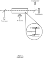
- An example Rydberg-atom based RF receiver is shown in Figure 1 and operates as follows.
- An atomic medium is provided which, in this example, is a glass cell filled with a low density vapour of alkali atoms (such as Rubidium-85).
- Each Rubidium-85 atom has a number of electron states, including the ground state (
- the outer electron of the Rubidium-85 atom may be excited (e.g. by absorbing a photon of a particular wavelength) from the ground state (
- the electron may then decay from the excited state to a lower excited state (that is, an excited state at a lower energy level) or to the ground state (
- a lower excited state that is, an excited state at a lower energy level
- some of these transitions are not allowed as they are dipole forbidden.
- a first laser (known as a "probe” laser) is passed through the atomic medium at a first wavelength which corresponds to the energy required to elevate the Rubidium-85 atom's outer electron from its ground state (11 >) to a first excited state (
- a second laser (known as a “coupling” laser) is also passed through the atomic medium in an opposing direction at a relatively large power level (compared to the probe laser) and at a second wavelength which corresponds to the energy required to elevate the Rubidium-85 atom's outer electron from the first excited state (
- 1>) is forbidden so that the ground state (
- This phenomenon is known as Electromagnetically Induced Transparency (EIT) and the received signal is known as the EIT signal.
- EIT Electromagnetically Induced Transparency
- the received signal is known as the EIT signal.
- EIT Electromagnetically Induced Transparency
- the received signal is known as the EIT signal.
- the above description is of a ladder scheme EIT effect, but the skilled person would understand that the EIT effect may be realised through alternative electron transitions, such as the Vee and Lambda schemes.
- a Rydberg-atom based FM RF receiver works in a similar manner. That is, when the RF electric field changes (or “detunes") from its resonant RF transition frequency, the EIT signal (on a graph of the EIT signal against probe laser detuning) splits into two non-symmetrical peaks. The separation of the two peaks increases with RF detuning. By locking the probe laser and coupling laser to particular frequencies, then the optical detector output is directly correlated to the FM RF electric field.
- Rydberg RF receivers may also be used to detect phase modulated RF fields, such as those of Binary Phase-Shift Keying (BPSK), Quadrature Phase-Shift Keying (QPSK), and Quadrature Amplitude Modulation (QAM) signals (used in many wireless and cellular communications protocols).
- phase modulated RF fields such as those of Binary Phase-Shift Keying (BPSK), Quadrature Phase-Shift Keying (QPSK), and Quadrature Amplitude Modulation (QAM) signals (used in many wireless and cellular communications protocols).
- BPSK Binary Phase-Shift Keying
- QPSK Quadrature Phase-Shift Keying
- QAM Quadrature Amplitude Modulation
- the Rydberg atom based RF detector may be configured to detect RF fields of a specific frequency by selecting a particular second wavelength of the coupling laser so that the electrons of the atomic medium are elevated to a particular Rydberg state.
- This Rydberg state is selected so that photons at the specific frequency to be detected will elevate electrons from this Rydberg state to another Rydberg state, thus creating a detectable change in the EIT signal that may be observed at the optical detector.
- the magnitude of the EIT signal known as the "modulation depth" is the difference between the depth of the drop in amplitude of the EIT signal when there is an incident RF electric field and when there is no incident RF electric field.
- US patent application publication number 2020/295838 A1 discloses a Rydberg atom mixer for determining a phase of modulated carrier radiation.
- a first wireless transceiver as claimed in Claim 1.
- the transmitter may be configured to transmit data to the wireless device in a forward-facing main lobe and transmit the local oscillator signal in a rear-facing lobe.
- the first wireless transceiver may further comprise an optical receiver for receiving the probe signal following the change caused by the combination of the phase-modulated signal and the local oscillator signal; and a processor configured to analyse the received probe signal to detect the phase state of the phase-modulated signal.
- the phase-modulated signal may be further modulated by amplitude and the processor may be further configured to analyse the received probe signal to detect the amplitude of the phase-modulated signal.
- the first wireless transceiver may be a base station for a cellular telecommunications network.
- the base station may further comprise a backhaul communications interface configured to receive the probe signal, following the change caused by the combination of the phase-modulated signal and the local oscillator signal, and communicate the received probe signal to a core network of the cellular telecommunications network.
- the base station may further comprise a wavelength converter configured to convert the received probe signal to a wavelength between 1260nm and 1625nm, wherein the wavelength converted received probe signal may be communicated to the core network.
- the first wireless transceiver may further comprise an optical receiver and a processor, and the method may further comprise the steps of: receiving, at the optical receiver, the probe signal following the change caused by the combination of the phase-modulated signal and the local oscillator signal; and analysing, at the processor, the received probe signal to detect the phase state of the phase-modulated signal.
- the phase-modulated signal may be further modulated by amplitude and the method may further comprise the step of analysing, at the processor, the received probe signal to further detect the amplitude of the phase-modulated signal.
- the first wireless transceiver may be a base station of a cellular telecommunications network and further comprises a backhaul communications interface, and the method may further comprise the steps of: receiving, at the backhaul communications interface, the probe signal following the change caused by the combination of the phase-modulated signal and the local oscillator signal; and communicating, by the backhaul communications interface, the received probe signal to a core network of the cellular telecommunications network.
- the first wireless transceiver may further comprise a wavelength converter, and the method may further comprise the steps of: converting, by the wavelength converter, the received probe signal to a wavelength between 1260nm and 1625nm, wherein the wavelength converted received probe signal may be communicated to the core network.
- a computer program as claimed in Claim 13 may be stored on a computer readable carrier medium.
- the wireless telecommunications network of this first embodiment is a cellular telecommunications network having a base station 100 and a User Equipment, UE, 200.
- the network employs a Time-Division-Duplexing (TDD) technique to permit bi-directional communication between the base station 100 and UE 200.
- TDD Time-Division-Duplexing
- the network is therefore configured to communicate according to a time frame structure in which the time frame is divided into a plurality of timeslots, wherein a first subset of the plurality of timeslots are for downlink transmissions (that is, from the base station 100 to the UE 200) and a second subset of the plurality of timeslots are for uplink transmissions (that is, from the UE 200 to the base station 100).
- the base station 100 and UE 200 are time synchronised (or at least frame synchronised) so that a start of a time frame in each entity is at a common time.
- This synchronisation is achieved by use of an atomic clock, such as a Rubidium or Caesium based atomic clock, in the base station 100 and by distribution of a synchronisation signal from the base station 100 to the UE 200 during connection establishment.
- a symbol rate is also communicated from the base station 100 to the UE 200 during connection establishment, which is thereafter used in communications between the base station 100 and UE 200.
- the synchronisation may be periodically updated by periodically distributing synchronisation signals so as to correct any clock drift between the base station 100 and UE 200.
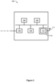
- the base station 100 is shown in more detail in Figure 3 .
- the base station 100 is a wireless transceiver having both a Radio Frequency (RF) transmitter 110, an RF receiver 120, a processor 130, memory 140 and a backhaul communications interface 150.
- RF Radio Frequency
- the RF transmitter 110 includes an antenna 111 and a transmitter processing module 113.
- the transmitter processing module 113 is configured for processing data (e.g. stored in memory 140 or received from the backhaul communications interface 150) for transmission by the antenna 111. This is explained in more detail below.
- the RF receiver 120 is a Rydberg-atom based RF receiver and includes an optical fibre 121, a probe laser 122 for transmitting a probe signal along the optical fibre 121 (illustrated by a solid arrowed line in Figure 4 ), a coupling laser 123 for transmitting a coupling signal along the optical fibre 121 (shown by a dashed arrowed line in Figure 4 , counter-propagating and overlapping the probe signal), a photodetector 124, a controller 125 and a receiver processing module 126.
- the receiver processing module 126 is configured for processing a signal of the photodetector 124 and, in this embodiment, is a Vector Signal Analyser (VSA).
- VSA Vector Signal Analyser
- the optical fibre 121 includes an optical cavity containing a vapour of alkali metal (in this embodiment, Rubidium-85).
- the controller 125 is for controlling a frequency of the probe signal (i.e. to adjust and/or stabilise the frequency of the probe signal), for controlling a frequency of the coupling signal (i.e. to adjust and/or stabilise the frequency of the coupling signal), for controlling an intensity of the probe laser 122 (i.e. the transmission power and/or cross-sectional area of the probe laser 122), and for controlling an intensity of the coupling laser 123 (i.e. the transmission power and/or cross-sectional area of the coupling laser 123).
- the backhaul communications interface 150 shown in Figure 3 connects the base station 100 (via an optical fibre link) to a core network (not shown). Data for the base station 100 and UE 200 shown in Figure 2 may be communicated via this backhaul communications interface.
- the network is configured for bi-directional communication between the base station 100 and UE 200.
- For downlink communications (from the base station 100 to the UE 200), this is achieved by the base station 100 transmitting data (such as locally stored data or data received from the core network) by the RF transmitter 110 during the first subset of the plurality of timeslots.
- the UE 200 is similarly configured to receive the data transmitted by the base station 100 in the first subset of the plurality of timeslots.
- the UE 200 For uplink communications (from the UE 200 to the base station 100), the UE 200 transmits wireless signals, in which data is modulated to the wireless signals using a 16-Quadrature Amplitude Modulation (QAM) modulation scheme, during the second subset of the plurality of timeslots. These wireless signals are transmitted at a frequency of around 3.5GHz.
- the RF transmitter 110 of the base station 100 is also configured to transmit a local oscillator signal during the second subset of the plurality of timeslots so as to enable the RF detector 120 of the base station 100 to detect the phase-modulated wireless signals transmitted by the UE 200 (this is discussed in more detail below).
- the local oscillator signal has a constant amplitude and phase during each timeslot of the second subset of timeslots.
- the frequency of the local oscillator signal is slightly off-resonance with the frequency of the UE's transmissions.
- the local oscillator signal has a frequency of 3.50000GHz, and the frequency of the UE's transmissions is 3.50003GHz (such that the frequency difference is 30kHz).
- Figure 2 illustrates the transmission coverage areas of the antenna 111.
- the antenna 111 has a forward-facing main lobe that covers a geographical region in which users are served by the base station 100 and therefore carries control and user plane data for these users (e.g. UE 200).
- the antenna 111 also has a rear-facing lobe that covers the RF receiver 120 and carries the local oscillator signal.
- the transmission power of the antenna 111 may be configured such that, during the second subset of timeslots, the rear-facing lobe covers the RF receiver 120 and a coverage area of the front-facing lobe is significantly smaller than its coverage area during the first subset of timeslots (so as to reduce interference between the local oscillator signal transmitted by the antenna 111 and the wireless signal transmitted by the UE 200).
- the RF receiver 120 is configured to detect these phase-modulated wireless signals by configuring the probe laser 122 of the RF receiver 120 to transmit a probe signal through the optical fibre 121, thus exciting electrons of the Rubidium-85 atoms of the optical cavity of the optical fibre 121, and by configuring the coupling laser 123 of the RF receiver 120 to transmit a coupling signal through the optical fibre 121 (counter-propagating and overlapping the probe signal), thus also exciting electrons of the Rubidium-85 atoms in the optical cavity of the optical fibre 121.
- the frequency of the probe signal is set to correlate with the transition of an electron of a Rubidium-85 atom from a ground state to a first excited state
- the frequency of the coupling signal is set to correlate with the transition of an electron of a Rubidium-85 atom from the first excited state to a predetermined Rydberg state.
- the predetermined Rydberg state is selected (based on the specific frequencies of the probe and coupling signals) so that a wireless signal, having a particular frequency, incident upon the optical cavity of the optical fibre 121 excites electrons from the predetermined Rydberg state to another Rydberg state, causing a detectable change in the Electromagnetically Induced Transparency (EIT) signal at the photodetector 124.
- the probe frequency is 780nm and the coupling frequency is 480nm so that electrons are excited to the 84 th Rydberg state.
- the RF transmitter 110 shown in Figure 3 is configured to transmit a local oscillator signal during the second subset of the plurality of timeslots.
- the local oscillator signal and the wireless signal have a frequency correlating with the transition from the predetermined Rydberg state to the other Rydberg state.
- the superposition of the local oscillator signal and the wireless signal at the optical cavity of the optical fibre 121 shown in Figure 4 modifies the probe signal such that the phase and amplitude of the wireless signal can be detected.
- This detection technique has been discussed in several papers, such as " A Rydberg Atom-Based Mixer: Measuring the Phase of a Radio Frequency Wave", Matthew T. Simons et al., and " Detecting and Receiving Phase Modulated Signals with a Rydberg Atom-Based Mixer", Christopher L. Holloway et al. A brief overview of the theory behind this detection will now be presented.
- E atroms cos ⁇ LO + ⁇ LO ⁇ E LO 2 + E SIG 2 + 2 E LO E SIG cos ⁇ ⁇ t + ⁇ ⁇
- the Rudbium-85 atoms of the optical cavity of the optical fibre 121 demodulate the high frequency field, ⁇ LO , such that the received probe signal, T probe , as a function of time is given by: T probe ⁇ E atoms ⁇ _ E LO + E SIG cos ⁇ ⁇ t + ⁇ ⁇
- the received probe signal therefore has a sinusoidal form with a frequency being the difference between the frequency of the local oscillator signal and the frequency of the wireless signal ( ⁇ ⁇ ) and a phase being the difference between the phase of the local oscillator signal and the phase of the wireless signal ( ⁇ ⁇ ). Accordingly, by measuring the relative phase shift of the received probe signal over time, the phase state of the wireless signal can be determined. Furthermore, an amplitude of the probe is a function of both the electric field strength of the local oscillator signal and the electric field strength of the wireless signal, such that the amplitude of the wireless signal may be determined from the amplitude of the received probe signal.
- each distinct amplitude of the plurality of amplitudes as transmitted by the UE 200 causes a distinct amplitude in the received probe signal as measured by the base station 200.
- Figure 5 is a graph of an example received probe signal against time for a plurality of symbols.
- the received probe signal is illustrated by the solid line and, as noted above, has a frequency equal to the difference between the frequency of the local oscillator signal and the frequency of the wireless signal.
- the graph also illustrates a reference signal in the short-dashed line having the same frequency as the received probe signal but has a constant phase (so as to illustrate a phase shift of the received probe signal), and a symbol interval in the long-dashed line defining the bounds of each symbol interval.
- This graph illustrates a series of symbol intervals in which the phase shift (between the received probe signal and the reference signal) in each symbol interval determines the phase state of that symbol in the wireless signal and the amplitude of the received probe signal in each symbol interval determines the amplitude of that symbol in the wireless signal.
- VSA 126 shown in Figure 4 is configured to monitor the received probe signal during the second subset of the plurality of timeslots in order to detect the phase state and amplitude of each symbol of the (16-QAM) phase-modulated wireless signal transmitted by the UE 200, and demodulate the data contained in these phase-modulated signals into a data stream.
- the demodulated data stream may then be processed locally by the base station 100 or transmitted to the core network via the backhaul communications interface 150 shown in Figure 3 .
- This first embodiment of the present invention therefore enables the base station 100 to utilise a Rydberg-atom based RF receiver, having its preferential technical benefits such as broad frequency range and high sensitivity compared to a conventional dipole antenna receiver, to receive phase-modulated wireless signals. Furthermore, this benefit is achieved without introducing additional hardware to provide the local oscillator signal as the same antenna that is used for downlink communications is utilised for the local oscillator signal.
- a first step, S101 the base station 100 establishes a connection with the UE 200 and adopts a time frame structure for communication, wherein the time frame includes a first set of timeslots for downlink communication and a second set of timeslots for uplink communication.
- step S103 the base station 100 determines whether it is entering a timeslot of the first set of timeslots for downlink communication or the second set of timeslots for uplink communication.
- the base station 100 is entering a timeslot of the first set of timeslots and so proceeds to step S105 in which it is configured to transmit wireless signals to the UE 200.
- step S103 the base station 100 enters a timeslot of the second set of timeslots and so proceeds to step S107 in which it is configured to 1) transmit a local oscillator signal and 2) receive the wireless signals from the UE 200.
- step S109 the VSA 126 of the base station 100 processes the received probe signal (as modified by the combination of the local oscillator signal and the wireless signal transmitted by the UE 200) and demodulates the data contained within the wireless signal.
- the method loops back to step S103.
- FIG. 7 illustrates an RF receiver of a base station of this second embodiment.
- This second embodiment is very similar to the first embodiment and the same reference numerals will be used for like-for-like components.
- This second embodiment differs from the first embodiment above in that the received probe signal is not processed at the base station 100 (such that the receiver processing module 226 of the RF receiver 120 of the second embodiment does not implement a VSA to analyse the probe signal). Instead, the probe signal is directed to the backhaul communications interface 150 for onward transmission to the core network.
- the received probe signal (and the data which is contained in the received probe signal due to the combination of the local oscillator signal and wireless signal at the optical cavity of the optical fibre) are therefore transported to the core network for demodulation into a demodulated data stream (e.g. by use of a VSA in the core network).
- the backhaul communications interface 150 includes a Periodically Poled Non-Linear (PPNL) optical waveguide which converts the frequency of the probe signal from 780nm to 1560nm. The difference signal is then carried on this 1560nm signal. The 1560nm signal is then passed to a Dense Wavelength Division Multiplexing (DWDM) grid for transmission to the core network.
- PPNL Periodically Poled Non-Linear
- DWDM Dense Wavelength Division Multiplexing
- This second embodiment of the present invention therefore benefits from a reduction in resource requirements for a base station for receiving phase-modulated wireless signals and transmitting the demodulated data stream from these wireless signals to the core network. That is, conventional base stations that utilise a dipole antenna for receiving phase-modulated wireless signals must demodulate the data stream from the received signals (which is carried out in the electrical domain) and convert this data stream to the optical domain in order to transmit the data stream to the core network via the backhaul communications interface.
- the processing resources required to perform such conversion adds a capital and operational (e.g. energy) cost to the base station. Furthermore, the conversion may increase noise in the signal, reducing signal quality.
- the phase-modulated wireless signals cause a change in the probe signal without any processing (that is, it is a result of the interaction of the Rubidium-85 atoms in the RF detector with the local oscillator and wireless signals) and is therefore directly converted from the wireless signal to the optical domain such that it may be backhauled over the optical link to the core network. There is therefore no processing or performance cost in domain-conversion.
- This second embodiment may therefore enjoy reduced capital costs, reduced operational costs and greater signal quality compared to conventional base stations.
- step S201 the base station 100 establishes a connection with the UE 200 and adopts a time frame structure for communication, wherein the time frame includes a first set of timeslots for downlink communication and a second set of timeslots for uplink communication.
- step S203 the base station 100 determines whether it is entering a timeslot of the first set of timeslots for downlink communication or the second set of timeslots for uplink communication.
- the base station 100 is entering a timeslot of the first set of timeslots and so proceeds to step S205 in which it is configured to transmit wireless signals to the UE 200.
- step S203 the base station 100 enters a timeslot of the second set of timeslots and so proceeds to step S207 in which it is configured to 1) transmit a local oscillator signal and 2) receive the wireless signals from the UE 200.
- step S209 the base station 100 backhauls the received probe signal to the core network for processing and demodulation.
- the method loops back to step S203.
- the received probe signal is converted to 1560nm before being transmitted to the core network as the 1560nm wavelength enjoys preferential long-range transmission characteristics in optical fibre (i.e. very low attenuation of approximately 0.3 dB/m) compared to the 780nm probe signal.
- the received probe signal may be converted to any wavelength between 1260nm and 1625nm. Nonetheless, the skilled person will understand that such wavelength conversion is non-essential.
- any wireless transceiver in any form of wireless telecommunications network may implement the present invention.
- a system may be configured such that an EIT signal is produced on a probe signal by an incident electromagnetic signal at that target frequency (such as by selecting an appropriate atomic medium (e.g. Rubidium, Caesium or Strontium) having Rydberg states that correspond with that target frequency).
- an appropriate atomic medium e.g. Rubidium, Caesium or Strontium
- the EIT signal is produced following a ladder configuration of electron transitions. That is, any configuration (e.g. Lambda, Vee) may be used.
- the atomic medium having Rydberg states corresponding with the target frequency is contained in an optical cavity of an optical fibre.
- the atomic medium may be contained in other arrangements, such as a glass cell. It is also non-essential that the RF receiver uses one or more lasers to produce the probe and coupling signals. That is, any other optical transmitter or coherent optical transmitter may be used instead (such as a Light Emitting Diode).
- phase-modulation scheme such as Binary Phase Shift Keying (BPSK), Quadrature Phase Shift Keying (QPSK), or a higher order of QAM, may be used instead.
- BPSK Binary Phase Shift Keying
- QPSK Quadrature Phase Shift Keying
- a higher order of QAM may be used instead.
- the difference between the frequency of the local oscillator signal and the wireless signal is around 30kHz. However, this is non-essential.
- the frequency difference may be another value (for example, between 1kHz and 10MHz) selected so as to avoid another electron transition.
Landscapes
- Physics & Mathematics (AREA)
- Electromagnetism (AREA)
- Engineering & Computer Science (AREA)
- Computer Networks & Wireless Communication (AREA)
- Signal Processing (AREA)
- General Physics & Mathematics (AREA)
- Optics & Photonics (AREA)
- Mobile Radio Communication Systems (AREA)
Claims (14)
- Erster drahtloser Sender-Empfänger (100) für ein drahtloses Telekommunikationsnetzwerk, wobei das drahtlose Telekommunikationsnetzwerk (100) einen zweiten drahtlosen Sender-Empfänger aufweist, wobei der erste drahtlose Sender-Empfänger (100) umfasst:einen Empfänger für elektromagnetische Felder (120), wobei der Empfänger für elektromagnetische Felder (120) einen ersten optischen Sender (122), einen zweiten optischen Sender (123) und ein Übertragungsmedium (121) umfasst, wobei der erste optische Sender (122) dazu konfiguriert ist, ein Sondensignal über das Übertragungsmedium (121) mit einer Sondenfrequenz zu übertragen, und der zweite Sender (123) dazu konfiguriert ist, ein Kopplungssignal über das Übertragungsmedium (121) mit einer Kopplungsfrequenz zu übertragen, wobei die Sondenfrequenz eingestellt wird, um Elektronen des Übertragungsmediums (121) von einem Grundzustand in einen ersten angeregten Zustand anzuregen, und die Kopplungsfrequenz eingestellt wird, um Elektronen des Übertragungsmediums (121) in einen vorbestimmten Rydberg-Zustand anzuregen, um einen Effekt der elektromagnetisch induzierten Transparenz, EIT, zu induzieren;dadurch gekennzeichnet, dass:Kommunikationen von dem ersten drahtlosen Sender-Empfänger (100) zu dem zweiten drahtlosen Sender-Empfänger während eines ersten Zeitschlitzes erfolgen und Kommunikationen von dem zweiten drahtlosen Sender-Empfänger zu dem ersten drahtlosen Sender-Empfänger (100) während eines zweiten Zeitschlitzes erfolgen;der erste drahtlose Sender-Empfänger (100) ferner einen Sender (110) umfasst, der dazu konfiguriert ist, während des ersten Zeitschlitzes Daten an den zweiten drahtlosen Sender-Empfänger zu senden und ferner dazu konfiguriert ist, während des zweiten Zeitschlitzes ein lokales Oszillatorsignal zu übertragen; undder Empfänger für elektromagnetische Felder (120) dazu konfiguriert ist, auf dem Übertragungsmedium (121) und während des zweiten Zeitschlitzes ein phasenmoduliertes Signal von dem zweiten drahtlosen Sender-Empfänger und das lokale Oszillatorsignal von dem Sender (110) zu empfangen, wobei eine Kombination des phasenmodulierten Signals und des lokalen Oszillatorsignals eine detektierbare Änderung des Sondensignals verursacht, aus der ein Phasenzustand des phasenmodulierten Signals detektiert werden kann.
- Erster drahtloser Sender-Empfänger (100) nach Anspruch 1, wobei der Sender (110) dazu konfiguriert ist, Daten an die drahtlose Vorrichtung in einer nach vorne gerichteten Hauptkeule zu übertragen und das lokale Oszillatorsignal in einer nach hinten gerichteten Keule zu übertragen.
- Erster drahtloser Sender-Empfänger (100) nach Anspruch 1 oder 2, der ferner umfasst:einen optischen Empfänger (124) zum Empfangen des Sondensignals, nach der Veränderung, die durch die Kombination des phasenmodulierten Signals und des lokalen Oszillatorsignals verursacht wird; undeinen Prozessor (126), der dazu konfiguriert ist, das empfangene Sondensignal zu analysieren, um den Phasenzustand des phasenmodulierten Signals zu detektieren.
- Erster drahtloser Sender-Empfänger (100) nach Anspruch 3, wobei das phasenmodulierte Signal ferner durch die Amplitude moduliert wird und der Prozessor ferner dazu konfiguriert ist, das empfangene Sondensignal zu analysieren, um die Amplitude des phasenmodulierten Signals zu detektieren.
- Erster drahtloser Sender-Empfänger (100) nach einem der vorhergehenden Ansprüche, der eine Basisstation für ein zellulares Telekommunikationsnetzwerk ist.
- Erster drahtloser Sender-Empfänger (100) nach Anspruch 5, wenn abhängig von Anspruch 1 oder Anspruch 2, der ferner eine Backhaul-Kommunikationsschnittstelle (150) umfasst, die dazu konfiguriert ist, das Sondensignal nach der durch die Kombination des phasenmodulierten Signals und des lokalen Oszillatorsignals verursachten Veränderung zu empfangen und das empfangene Sondensignal an ein Kernnetzwerk des zellularen Telekommunikationsnetzwerks zu kommunizieren.
- Erster drahtloser Sender-Empfänger (100) nach Anspruch 6, der ferner einen Wellenlängenwandler umfasst, der dazu konfiguriert ist, das empfangene Sondensignal in eine Wellenlänge zwischen 1260 nm und 1625 nm umzuwandeln, wobei das in der Wellenlänge umgewandelte empfangene Sondensignal an das Kernnetzwerk kommuniziert wird.
- Verfahren zum Betreiben eines ersten drahtlosen Sender-Empfängers (100) in einem drahtlosen Telekommunikationsnetzwerk, wobei das drahtlose Telekommunikationsnetzwerk einen zweiten drahtlosen Sender-Empfänger aufweist, wobei während eines ersten Zeitschlitzes eine Kommunikationen von dem ersten drahtlosen Sender-Empfänger (100) zu dem zweiten drahtlosen Sender-Empfänger erfolgen und während eines zweiten Zeitschlitzes Kommunikationen von dem zweiten drahtlosen Sender-Empfänger zu dem ersten drahtlosen Sender-Empfänger (100 während eines zweiten Zeitschlitzes erfolgen, wobei der erste drahtlose Sender-Empfänger (100) einen Sender (110) und einen Empfänger (120) für elektromagnetische Felder umfasst, wobei der Empfänger (120) für elektromagnetische Felder einen ersten optischen Sender (122), einen zweiten optischen Sender (123) und ein Übertragungsmedium (121) beinhaltet, wobei das Verfahren die folgenden Schritte umfasst:Übertragen eines Sondensignals durch den ersten optischen Sender (122) durch das Übertragungsmedium (121) bei einer Sondenfrequenz, die eingestellt wird, um Elektronen des Übertragungsmediums (121) von einem Grundzustand in einen ersten angeregten Zustand anzuregen;Übertragen eines Kopplungssignals durch den zweiten optischen Sender (123) durch das Übertragungsmedium (121) bei einer Kopplungsfrequenz, die eingestellt wird, um Elektronen des Übertragungsmediums (121) in einen vorbestimmten Rydberg-Zustand anzuregen, um einen Effekt der elektromagnetisch induzierten Transparenz (EIT) zu induzieren;wobei das Verfahren gekennzeichnet ist durch:Übertragen von Daten durch den Sender (110) an den zweiten drahtlosen Sender-Empfänger während des ersten Zeitschlitzes und eines lokalen Oszillatorsignals während des zweiten Zeitschlitzes; undEmpfangen eines phasenmodulierten Signals von dem zweiten drahtlosen Sender-Empfänger und des lokalen Oszillatorsignals von dem Sender (110) an dem Übertragungsmedium (121) des Empfängers (120) für elektromagnetische Felder während des zweiten Zeitschlitzes, wobei eine Kombination des phasenmodulierten Signals und des lokalen Oszillatorsignals eine detektierbare Veränderung des Sondensignals verursacht, aus der ein Phasenzustand des phasenmodulierten Signals detektiert werden kann.
- Verfahren nach Anspruch 8, wobei der erste drahtlose Sender-Empfänger (100) ferner einen optischen Empfänger (124) und einen Prozessor (126) umfasst und das Verfahren ferner die folgenden Schritte umfasst:Empfangen an dem optischen Empfänger (124) des Sondensignals, nach der Veränderung, die durch die Kombination des phasenmodulierten Signals und des lokalen Oszillatorsignals verursacht wird; undAnalysieren des empfangenen Sondensignals am Prozessor (126), um den Phasenzustand des phasenmodulierten Signals zu detektieren.
- Verfahren nach Anspruch 9, wobei das phasenmodulierte Signal ferner durch die Amplitude moduliert wird und das Verfahren ferner den Schritt des Analysierens des empfangenen Sondensignals in dem Prozessor umfasst, um ferner die Amplitude des phasenmodulierten Signals zu detektieren.
- Verfahren nach Anspruch 8, wobei der erste drahtlose Sender-Empfänger (100) eine Basisstation eines zellularen Telekommunikationsnetzwerks ist und ferner eine Backhaul-Kommunikationsschnittstelle (150) umfasst, und das Verfahren ferner die folgenden Schritte umfasst:Empfangen, an der Backhaul-Kommunikationsschnittstelle (150), des Sondensignals, nach der Veränderung, die durch die Kombination des phasenmodulierten Signals und des lokalen Oszillatorsignals verursacht wird; undKommunizieren des empfangenen Sondensignals durch die Backhaul-Kommunikationsschnittstelle (150) an ein Kernnetzwerk des zellularen Telekommunikationsnetzwerks.
- Verfahren nach Anspruch 11, wobei der erste drahtlose Sender-Empfänger (100) ferner einen Wellenlängenwandler umfasst und das Verfahren ferner die folgenden Schritte umfasst: Umwandeln des empfangenen Sondensignals in eine Wellenlänge zwischen 1260 nm und 1625 nm durch den Wellenlängenwandler, wobei das in der Wellenlänge umgewandelte empfangene Sondensignal an das Kernnetzwerk kommuniziert wird.
- Computerprogramm, das Anweisungen umfasst, die, wenn das Programm von einem ersten drahtlosen Sender-Empfänger ausgeführt wird, wie in einem der Ansprüche 1 bis 7 beansprucht, den ersten drahtlosen Sender-Empfänger veranlassen, die Schritte nach einem der Ansprüche 8 bis 12 durchzuführen.
- Computerlesbares Trägermedium, das das Computerprogramm nach Anspruch 13 umfasst.
Applications Claiming Priority (2)
| Application Number | Priority Date | Filing Date | Title |
|---|---|---|---|
| GB2105981.1A GB2606167B (en) | 2021-04-27 | 2021-04-27 | Wireless transceiver |
| PCT/EP2022/055577 WO2022228758A1 (en) | 2021-04-27 | 2022-03-04 | Wireless transceiver |
Publications (2)
| Publication Number | Publication Date |
|---|---|
| EP4331143A1 EP4331143A1 (de) | 2024-03-06 |
| EP4331143B1 true EP4331143B1 (de) | 2024-11-13 |
Family
ID=76193393
Family Applications (1)
| Application Number | Title | Priority Date | Filing Date |
|---|---|---|---|
| EP22713562.1A Active EP4331143B1 (de) | 2021-04-27 | 2022-03-04 | Drahtloser sender-empfänger |
Country Status (5)
| Country | Link |
|---|---|
| US (1) | US12028111B1 (de) |
| EP (1) | EP4331143B1 (de) |
| CN (1) | CN117256112A (de) |
| GB (1) | GB2606167B (de) |
| WO (1) | WO2022228758A1 (de) |
Families Citing this family (8)
| Publication number | Priority date | Publication date | Assignee | Title |
|---|---|---|---|---|
| CN114424111B (zh) | 2019-10-24 | 2022-12-27 | 英国电讯有限公司 | 传播信号的设备和系统以及电磁场检测器及操作其的方法 |
| GB2597260B (en) | 2020-07-16 | 2022-12-07 | British Telecomm | Electromagnetic field receiver |
| GB2606167B (en) | 2021-04-27 | 2023-06-21 | British Telecomm | Wireless transceiver |
| EP4277166A1 (de) * | 2022-05-13 | 2023-11-15 | British Telecommunications public limited company | Detektor für elektromagnetische felder |
| EP4569338B1 (de) | 2022-08-10 | 2026-02-18 | British Telecommunications Public Limited Company | Detektor für elektromagnetische felder |
| WO2025255139A1 (en) * | 2024-06-03 | 2025-12-11 | T-Mobile Innovations Llc | Radio with integrate rydberg sensor |
| US20250370020A1 (en) * | 2024-06-03 | 2025-12-04 | T-Mobile Innovations Llc | Rydberg sensor active antenna radio |
| US20260045703A1 (en) * | 2024-08-08 | 2026-02-12 | T-Mobile Usa, Inc. | Electronic device with a receiver including rydberg sensors |
Family Cites Families (21)
| Publication number | Priority date | Publication date | Assignee | Title |
|---|---|---|---|---|
| KR100762637B1 (ko) | 2006-05-03 | 2007-10-01 | 삼성전자주식회사 | Tdd 방식의 무선 시스템 신호 전송을 위한 단일 파장양방향 rof 링크 장치 |
| DE102017119212A1 (de) * | 2016-12-20 | 2018-06-21 | Infineon Technologies Ag | HF-Transceiver mit Testmöglichkeit |
| EP4542237A3 (de) | 2017-12-18 | 2025-06-25 | Rydberg Technologies Inc. | Messelement für atombasiertes elektromagnetisches feld und messsystem |
| CN108809341B (zh) | 2018-05-25 | 2020-04-17 | 山西大学 | 一种基于里德堡原子的量子天线调频波接收装置和方法 |
| US11349569B2 (en) * | 2018-10-26 | 2022-05-31 | Raytheon Company | Methods and apparatus for implementing an optical transceiver using a vapor cell |
| US10509065B1 (en) * | 2018-12-31 | 2019-12-17 | Quantum Valley Ideas Laboratories | Imaging of electromagnetic fields |
| US10979147B2 (en) * | 2019-03-11 | 2021-04-13 | Government Of The United States Of America, As Represented By The Secretary Of Commerce | Rydberg atom mixer and determining phase of modulated carrier radiation |
| CN109905177A (zh) * | 2019-03-13 | 2019-06-18 | 华南师范大学 | 基于微波光波相干转换的无线数字通信接收天线及其方法 |
| US10763966B1 (en) * | 2019-03-25 | 2020-09-01 | Otago Innovation Limited | Data communications system using an optical antenna |
| CN110518985B (zh) * | 2019-07-08 | 2022-09-02 | 清远市天之衡传感科技有限公司 | 基于里德堡原子混频器的无线数字通信系统及方法 |
| US20210091819A1 (en) * | 2019-09-20 | 2021-03-25 | Qualcomm Incorporated | Dynamic switching of local oscillator signal frequency for up-conversion and down-conversion in time division duplex wireless communication |
| GB2588754B (en) * | 2019-10-24 | 2022-05-11 | British Telecomm | Wireless telecommunications network |
| CN114424111B (zh) | 2019-10-24 | 2022-12-27 | 英国电讯有限公司 | 传播信号的设备和系统以及电磁场检测器及操作其的方法 |
| US11165505B2 (en) | 2020-02-12 | 2021-11-02 | Government Of The United States Of America, As Represented By The Secretary Of Commerce | Quantum atomic receiving antenna and quantum sensing of radiofrequency radiation |
| US11592469B2 (en) * | 2020-05-29 | 2023-02-28 | Rydberg Technologies Inc. | Atom-based closed-loop control for electromagnetic radiation measurement, communications, and information processing |
| GB2597260B (en) | 2020-07-16 | 2022-12-07 | British Telecomm | Electromagnetic field receiver |
| CA3199726A1 (en) * | 2020-12-17 | 2022-06-23 | Thad G. Walker | Electrometer sensor control system |
| GB2605123B (en) * | 2021-03-01 | 2023-04-26 | British Telecomm | Electromagnetic field detector |
| GB2606167B (en) | 2021-04-27 | 2023-06-21 | British Telecomm | Wireless transceiver |
| CN113504415B (zh) | 2021-06-01 | 2023-07-21 | 中国科学院大学 | 一种里德堡原子微波鉴相器系统及其相位测量方法 |
| US11402479B1 (en) | 2022-02-08 | 2022-08-02 | Quantum Valley Ideas Laboratories | Communicating information using photonic crystal transceivers |
-
2021
- 2021-04-27 GB GB2105981.1A patent/GB2606167B/en active Active
-
2022
- 2022-03-04 EP EP22713562.1A patent/EP4331143B1/de active Active
- 2022-03-04 US US18/556,887 patent/US12028111B1/en active Active
- 2022-03-04 WO PCT/EP2022/055577 patent/WO2022228758A1/en not_active Ceased
- 2022-03-04 CN CN202280030919.8A patent/CN117256112A/zh active Pending
Also Published As
| Publication number | Publication date |
|---|---|
| GB2606167B (en) | 2023-06-21 |
| US12028111B1 (en) | 2024-07-02 |
| EP4331143A1 (de) | 2024-03-06 |
| US20240204876A1 (en) | 2024-06-20 |
| CN117256112A (zh) | 2023-12-19 |
| GB2606167A (en) | 2022-11-02 |
| WO2022228758A1 (en) | 2022-11-03 |
| GB202105981D0 (en) | 2021-06-09 |
Similar Documents
| Publication | Publication Date | Title |
|---|---|---|
| EP4331143B1 (de) | Drahtloser sender-empfänger | |
| EP1357683B1 (de) | Hybrides Faser-Funksystem | |
| EP4150353B1 (de) | Empfänger für elektromagnetisches feld | |
| US12250025B2 (en) | Electromagnetic field receiver | |
| Maekawa et al. | Single-channel 240-Gbit/s sub-THz wireless communications using ultra-low phase noise receiver | |
| Ali et al. | Analysis of a framework implementation of the transceiver performances for integrating optical technologies and wireless LAN based on OFDM-RoF | |
| JP2005528011A (ja) | 能動的な後方散乱トランスポンダ、この種の後方散乱トランスポンダを備えた通信システムおよびこの種の能動的な後方散乱トランスポンダを用いるデータ伝送方法 | |
| Choi et al. | A 60-GHz point-to-multipoint millimeter-wave fiber-radio communication system | |
| CN116261833B (zh) | 电信网络 | |
| Chen et al. | New paradigm for integrated sensing and communication with Rydberg atomic receiver | |
| US12411162B2 (en) | Electromagnetic field detector | |
| Gao et al. | Self-heterodyne detection with SiC Fermi-level managed barrier diode at 300-GHz band | |
| Shoji et al. | 70-GHz-band MMIC transceiver with integrated antenna diversity system: application of receiver-module-arrayed self-heterodyne technique | |
| CN113472447A (zh) | 一种基于原子的太赫兹接收机通信系统和方法 | |
| CN114785419B (zh) | 信号接收装置与信号接收方法 | |
| Wang et al. | Rydberg atomic receiver for AM, FM, and phase shift keying data transmission | |
| Lyu et al. | LFM-PSK-based integrated sensing and communication system in the THz band | |
| Dennis et al. | Broadband data transmission in a 40 GHz fiber radio link using a dual-wavelength SBS fiber laser | |
| Ikeda et al. | Simultaneous 3-band modulation 2.5-Gb/s baseband, microwave-, and 60-GHz-band signals using a single electroabsorption modulator for radio-on-fiber systems | |
| JP2000091939A (ja) | 周波数変換装置及びそれを用いた無線通信システム | |
| Kwong et al. | Coherent-detection of narrow-linewidth millimeter-wave and microwave subcarrier signals for future mobile/personal communications |
Legal Events
| Date | Code | Title | Description |
|---|---|---|---|
| STAA | Information on the status of an ep patent application or granted ep patent |
Free format text: STATUS: UNKNOWN |
|
| STAA | Information on the status of an ep patent application or granted ep patent |
Free format text: STATUS: THE INTERNATIONAL PUBLICATION HAS BEEN MADE |
|
| PUAI | Public reference made under article 153(3) epc to a published international application that has entered the european phase |
Free format text: ORIGINAL CODE: 0009012 |
|
| STAA | Information on the status of an ep patent application or granted ep patent |
Free format text: STATUS: REQUEST FOR EXAMINATION WAS MADE |
|
| 17P | Request for examination filed |
Effective date: 20230919 |
|
| AK | Designated contracting states |
Kind code of ref document: A1 Designated state(s): AL AT BE BG CH CY CZ DE DK EE ES FI FR GB GR HR HU IE IS IT LI LT LU LV MC MK MT NL NO PL PT RO RS SE SI SK SM TR |
|
| GRAP | Despatch of communication of intention to grant a patent |
Free format text: ORIGINAL CODE: EPIDOSNIGR1 |
|
| STAA | Information on the status of an ep patent application or granted ep patent |
Free format text: STATUS: GRANT OF PATENT IS INTENDED |
|
| DAV | Request for validation of the european patent (deleted) | ||
| DAX | Request for extension of the european patent (deleted) | ||
| INTG | Intention to grant announced |
Effective date: 20240619 |
|
| GRAS | Grant fee paid |
Free format text: ORIGINAL CODE: EPIDOSNIGR3 |
|
| GRAA | (expected) grant |
Free format text: ORIGINAL CODE: 0009210 |
|
| STAA | Information on the status of an ep patent application or granted ep patent |
Free format text: STATUS: THE PATENT HAS BEEN GRANTED |
|
| AK | Designated contracting states |
Kind code of ref document: B1 Designated state(s): AL AT BE BG CH CY CZ DE DK EE ES FI FR GB GR HR HU IE IS IT LI LT LU LV MC MK MT NL NO PL PT RO RS SE SI SK SM TR |
|
| REG | Reference to a national code |
Ref country code: GB Ref legal event code: FG4D |
|
| REG | Reference to a national code |
Ref country code: CH Ref legal event code: EP |
|
| REG | Reference to a national code |
Ref country code: DE Ref legal event code: R096 Ref document number: 602022007728 Country of ref document: DE |
|
| REG | Reference to a national code |
Ref country code: IE Ref legal event code: FG4D |
|
| REG | Reference to a national code |
Ref country code: LT Ref legal event code: MG9D |
|
| P01 | Opt-out of the competence of the unified patent court (upc) registered |
Free format text: CASE NUMBER: APP_5586/2025 Effective date: 20250203 |
|
| REG | Reference to a national code |
Ref country code: NL Ref legal event code: MP Effective date: 20241113 |
|
| PG25 | Lapsed in a contracting state [announced via postgrant information from national office to epo] |
Ref country code: HR Free format text: LAPSE BECAUSE OF FAILURE TO SUBMIT A TRANSLATION OF THE DESCRIPTION OR TO PAY THE FEE WITHIN THE PRESCRIBED TIME-LIMIT Effective date: 20241113 Ref country code: PT Free format text: LAPSE BECAUSE OF FAILURE TO SUBMIT A TRANSLATION OF THE DESCRIPTION OR TO PAY THE FEE WITHIN THE PRESCRIBED TIME-LIMIT Effective date: 20250313 Ref country code: IS Free format text: LAPSE BECAUSE OF FAILURE TO SUBMIT A TRANSLATION OF THE DESCRIPTION OR TO PAY THE FEE WITHIN THE PRESCRIBED TIME-LIMIT Effective date: 20250313 |
|
| PG25 | Lapsed in a contracting state [announced via postgrant information from national office to epo] |
Ref country code: FI Free format text: LAPSE BECAUSE OF FAILURE TO SUBMIT A TRANSLATION OF THE DESCRIPTION OR TO PAY THE FEE WITHIN THE PRESCRIBED TIME-LIMIT Effective date: 20241113 Ref country code: NL Free format text: LAPSE BECAUSE OF FAILURE TO SUBMIT A TRANSLATION OF THE DESCRIPTION OR TO PAY THE FEE WITHIN THE PRESCRIBED TIME-LIMIT Effective date: 20241113 |
|
| REG | Reference to a national code |
Ref country code: AT Ref legal event code: MK05 Ref document number: 1742452 Country of ref document: AT Kind code of ref document: T Effective date: 20241113 |
|
| PG25 | Lapsed in a contracting state [announced via postgrant information from national office to epo] |
Ref country code: BG Free format text: LAPSE BECAUSE OF FAILURE TO SUBMIT A TRANSLATION OF THE DESCRIPTION OR TO PAY THE FEE WITHIN THE PRESCRIBED TIME-LIMIT Effective date: 20241113 |
|
| PG25 | Lapsed in a contracting state [announced via postgrant information from national office to epo] |
Ref country code: ES Free format text: LAPSE BECAUSE OF FAILURE TO SUBMIT A TRANSLATION OF THE DESCRIPTION OR TO PAY THE FEE WITHIN THE PRESCRIBED TIME-LIMIT Effective date: 20241113 |
|
| PG25 | Lapsed in a contracting state [announced via postgrant information from national office to epo] |
Ref country code: NO Free format text: LAPSE BECAUSE OF FAILURE TO SUBMIT A TRANSLATION OF THE DESCRIPTION OR TO PAY THE FEE WITHIN THE PRESCRIBED TIME-LIMIT Effective date: 20250213 |
|
| PG25 | Lapsed in a contracting state [announced via postgrant information from national office to epo] |
Ref country code: AT Free format text: LAPSE BECAUSE OF FAILURE TO SUBMIT A TRANSLATION OF THE DESCRIPTION OR TO PAY THE FEE WITHIN THE PRESCRIBED TIME-LIMIT Effective date: 20241113 Ref country code: GR Free format text: LAPSE BECAUSE OF FAILURE TO SUBMIT A TRANSLATION OF THE DESCRIPTION OR TO PAY THE FEE WITHIN THE PRESCRIBED TIME-LIMIT Effective date: 20250214 Ref country code: LV Free format text: LAPSE BECAUSE OF FAILURE TO SUBMIT A TRANSLATION OF THE DESCRIPTION OR TO PAY THE FEE WITHIN THE PRESCRIBED TIME-LIMIT Effective date: 20241113 |
|
| PG25 | Lapsed in a contracting state [announced via postgrant information from national office to epo] |
Ref country code: PL Free format text: LAPSE BECAUSE OF FAILURE TO SUBMIT A TRANSLATION OF THE DESCRIPTION OR TO PAY THE FEE WITHIN THE PRESCRIBED TIME-LIMIT Effective date: 20241113 |
|
| PG25 | Lapsed in a contracting state [announced via postgrant information from national office to epo] |
Ref country code: RS Free format text: LAPSE BECAUSE OF FAILURE TO SUBMIT A TRANSLATION OF THE DESCRIPTION OR TO PAY THE FEE WITHIN THE PRESCRIBED TIME-LIMIT Effective date: 20250213 |
|
| PG25 | Lapsed in a contracting state [announced via postgrant information from national office to epo] |
Ref country code: SM Free format text: LAPSE BECAUSE OF FAILURE TO SUBMIT A TRANSLATION OF THE DESCRIPTION OR TO PAY THE FEE WITHIN THE PRESCRIBED TIME-LIMIT Effective date: 20241113 |
|
| PG25 | Lapsed in a contracting state [announced via postgrant information from national office to epo] |
Ref country code: DK Free format text: LAPSE BECAUSE OF FAILURE TO SUBMIT A TRANSLATION OF THE DESCRIPTION OR TO PAY THE FEE WITHIN THE PRESCRIBED TIME-LIMIT Effective date: 20241113 |
|
| PG25 | Lapsed in a contracting state [announced via postgrant information from national office to epo] |
Ref country code: EE Free format text: LAPSE BECAUSE OF FAILURE TO SUBMIT A TRANSLATION OF THE DESCRIPTION OR TO PAY THE FEE WITHIN THE PRESCRIBED TIME-LIMIT Effective date: 20241113 |
|
| PG25 | Lapsed in a contracting state [announced via postgrant information from national office to epo] |
Ref country code: RO Free format text: LAPSE BECAUSE OF FAILURE TO SUBMIT A TRANSLATION OF THE DESCRIPTION OR TO PAY THE FEE WITHIN THE PRESCRIBED TIME-LIMIT Effective date: 20241113 |
|
| PG25 | Lapsed in a contracting state [announced via postgrant information from national office to epo] |
Ref country code: SK Free format text: LAPSE BECAUSE OF FAILURE TO SUBMIT A TRANSLATION OF THE DESCRIPTION OR TO PAY THE FEE WITHIN THE PRESCRIBED TIME-LIMIT Effective date: 20241113 |
|
| PG25 | Lapsed in a contracting state [announced via postgrant information from national office to epo] |
Ref country code: CZ Free format text: LAPSE BECAUSE OF FAILURE TO SUBMIT A TRANSLATION OF THE DESCRIPTION OR TO PAY THE FEE WITHIN THE PRESCRIBED TIME-LIMIT Effective date: 20241113 |
|
| PG25 | Lapsed in a contracting state [announced via postgrant information from national office to epo] |
Ref country code: IT Free format text: LAPSE BECAUSE OF FAILURE TO SUBMIT A TRANSLATION OF THE DESCRIPTION OR TO PAY THE FEE WITHIN THE PRESCRIBED TIME-LIMIT Effective date: 20241113 |
|
| REG | Reference to a national code |
Ref country code: DE Ref legal event code: R097 Ref document number: 602022007728 Country of ref document: DE |
|
| PG25 | Lapsed in a contracting state [announced via postgrant information from national office to epo] |
Ref country code: SE Free format text: LAPSE BECAUSE OF FAILURE TO SUBMIT A TRANSLATION OF THE DESCRIPTION OR TO PAY THE FEE WITHIN THE PRESCRIBED TIME-LIMIT Effective date: 20241113 |
|
| PLBE | No opposition filed within time limit |
Free format text: ORIGINAL CODE: 0009261 |
|
| STAA | Information on the status of an ep patent application or granted ep patent |
Free format text: STATUS: NO OPPOSITION FILED WITHIN TIME LIMIT |
|
| PG25 | Lapsed in a contracting state [announced via postgrant information from national office to epo] |
Ref country code: MC Free format text: LAPSE BECAUSE OF FAILURE TO SUBMIT A TRANSLATION OF THE DESCRIPTION OR TO PAY THE FEE WITHIN THE PRESCRIBED TIME-LIMIT Effective date: 20241113 |
|
| 26N | No opposition filed |
Effective date: 20250814 |
|
| REG | Reference to a national code |
Ref country code: CH Ref legal event code: H13 Free format text: ST27 STATUS EVENT CODE: U-0-0-H10-H13 (AS PROVIDED BY THE NATIONAL OFFICE) Effective date: 20251023 |
|
| PG25 | Lapsed in a contracting state [announced via postgrant information from national office to epo] |
Ref country code: LU Free format text: LAPSE BECAUSE OF NON-PAYMENT OF DUE FEES Effective date: 20250304 |
|
| REG | Reference to a national code |
Ref country code: BE Ref legal event code: MM Effective date: 20250331 |
|
| PG25 | Lapsed in a contracting state [announced via postgrant information from national office to epo] |
Ref country code: BE Free format text: LAPSE BECAUSE OF NON-PAYMENT OF DUE FEES Effective date: 20250331 |
|
| PG25 | Lapsed in a contracting state [announced via postgrant information from national office to epo] |
Ref country code: CH Free format text: LAPSE BECAUSE OF NON-PAYMENT OF DUE FEES Effective date: 20250331 |
|
| PG25 | Lapsed in a contracting state [announced via postgrant information from national office to epo] |
Ref country code: IE Free format text: LAPSE BECAUSE OF NON-PAYMENT OF DUE FEES Effective date: 20250304 |
|
| PGFP | Annual fee paid to national office [announced via postgrant information from national office to epo] |
Ref country code: GB Payment date: 20260220 Year of fee payment: 5 |
|
| PGFP | Annual fee paid to national office [announced via postgrant information from national office to epo] |
Ref country code: DE Payment date: 20260219 Year of fee payment: 5 |
|
| PGFP | Annual fee paid to national office [announced via postgrant information from national office to epo] |
Ref country code: FR Payment date: 20260220 Year of fee payment: 5 |