EP4330111B1 - Verfahren und system zur erzeugung von druckluft von mindestens einem fahrzeug, insbesondere mindestens einem schienenfahrzeug - Google Patents
Verfahren und system zur erzeugung von druckluft von mindestens einem fahrzeug, insbesondere mindestens einem schienenfahrzeug Download PDFInfo
- Publication number
- EP4330111B1 EP4330111B1 EP22727978.3A EP22727978A EP4330111B1 EP 4330111 B1 EP4330111 B1 EP 4330111B1 EP 22727978 A EP22727978 A EP 22727978A EP 4330111 B1 EP4330111 B1 EP 4330111B1
- Authority
- EP
- European Patent Office
- Prior art keywords
- pressure value
- compressor
- electric motor
- state
- predetermined pressure
- Prior art date
- Legal status (The legal status is an assumption and is not a legal conclusion. Google has not performed a legal analysis and makes no representation as to the accuracy of the status listed.)
- Active
Links
Images


Classifications
-
- B—PERFORMING OPERATIONS; TRANSPORTING
- B60—VEHICLES IN GENERAL
- B60T—VEHICLE BRAKE CONTROL SYSTEMS OR PARTS THEREOF; BRAKE CONTROL SYSTEMS OR PARTS THEREOF, IN GENERAL; ARRANGEMENT OF BRAKING ELEMENTS ON VEHICLES IN GENERAL; PORTABLE DEVICES FOR PREVENTING UNWANTED MOVEMENT OF VEHICLES; VEHICLE MODIFICATIONS TO FACILITATE COOLING OF BRAKES
- B60T17/00—Component parts, details, or accessories of power brake systems not covered by groups B60T8/00, B60T13/00 or B60T15/00, or presenting other characteristic features
- B60T17/02—Arrangements of pumps or compressors, or control devices therefor
-
- B—PERFORMING OPERATIONS; TRANSPORTING
- B60—VEHICLES IN GENERAL
- B60T—VEHICLE BRAKE CONTROL SYSTEMS OR PARTS THEREOF; BRAKE CONTROL SYSTEMS OR PARTS THEREOF, IN GENERAL; ARRANGEMENT OF BRAKING ELEMENTS ON VEHICLES IN GENERAL; PORTABLE DEVICES FOR PREVENTING UNWANTED MOVEMENT OF VEHICLES; VEHICLE MODIFICATIONS TO FACILITATE COOLING OF BRAKES
- B60T13/00—Transmitting braking action from initiating means to ultimate brake actuator with power assistance or drive; Brake systems incorporating such transmitting means, e.g. air-pressure brake systems
- B60T13/10—Transmitting braking action from initiating means to ultimate brake actuator with power assistance or drive; Brake systems incorporating such transmitting means, e.g. air-pressure brake systems with fluid assistance, drive, or release
- B60T13/66—Electrical control in fluid-pressure brake systems
- B60T13/665—Electrical control in fluid-pressure brake systems the systems being specially adapted for transferring two or more command signals, e.g. railway systems
-
- B—PERFORMING OPERATIONS; TRANSPORTING
- B60—VEHICLES IN GENERAL
- B60T—VEHICLE BRAKE CONTROL SYSTEMS OR PARTS THEREOF; BRAKE CONTROL SYSTEMS OR PARTS THEREOF, IN GENERAL; ARRANGEMENT OF BRAKING ELEMENTS ON VEHICLES IN GENERAL; PORTABLE DEVICES FOR PREVENTING UNWANTED MOVEMENT OF VEHICLES; VEHICLE MODIFICATIONS TO FACILITATE COOLING OF BRAKES
- B60T17/00—Component parts, details, or accessories of power brake systems not covered by groups B60T8/00, B60T13/00 or B60T15/00, or presenting other characteristic features
- B60T17/18—Safety devices; Monitoring
- B60T17/22—Devices for monitoring or checking brake systems; Signal devices
- B60T17/228—Devices for monitoring or checking brake systems; Signal devices for railway vehicles
-
- B—PERFORMING OPERATIONS; TRANSPORTING
- B61—RAILWAYS
- B61H—BRAKES OR OTHER RETARDING DEVICES SPECIALLY ADAPTED FOR RAIL VEHICLES; ARRANGEMENT OR DISPOSITION THEREOF IN RAIL VEHICLES
- B61H13/00—Actuating rail-vehicle brakes
-
- B—PERFORMING OPERATIONS; TRANSPORTING
- B61—RAILWAYS
- B61H—BRAKES OR OTHER RETARDING DEVICES SPECIALLY ADAPTED FOR RAIL VEHICLES; ARRANGEMENT OR DISPOSITION THEREOF IN RAIL VEHICLES
- B61H13/00—Actuating rail-vehicle brakes
- B61H13/20—Transmitting mechanisms
-
- B—PERFORMING OPERATIONS; TRANSPORTING
- B61—RAILWAYS
- B61H—BRAKES OR OTHER RETARDING DEVICES SPECIALLY ADAPTED FOR RAIL VEHICLES; ARRANGEMENT OR DISPOSITION THEREOF IN RAIL VEHICLES
- B61H13/00—Actuating rail-vehicle brakes
- B61H13/34—Details
-
- F—MECHANICAL ENGINEERING; LIGHTING; HEATING; WEAPONS; BLASTING
- F04—POSITIVE - DISPLACEMENT MACHINES FOR LIQUIDS; PUMPS FOR LIQUIDS OR ELASTIC FLUIDS
- F04B—POSITIVE-DISPLACEMENT MACHINES FOR LIQUIDS; PUMPS
- F04B35/00—Piston pumps specially adapted for elastic fluids and characterised by the driving means to their working members, or by combination with, or adaptation to, specific driving engines or motors, not otherwise provided for
- F04B35/04—Piston pumps specially adapted for elastic fluids and characterised by the driving means to their working members, or by combination with, or adaptation to, specific driving engines or motors, not otherwise provided for the means being electric
-
- F—MECHANICAL ENGINEERING; LIGHTING; HEATING; WEAPONS; BLASTING
- F04—POSITIVE - DISPLACEMENT MACHINES FOR LIQUIDS; PUMPS FOR LIQUIDS OR ELASTIC FLUIDS
- F04B—POSITIVE-DISPLACEMENT MACHINES FOR LIQUIDS; PUMPS
- F04B41/00—Pumping installations or systems specially adapted for elastic fluids
- F04B41/02—Pumping installations or systems specially adapted for elastic fluids having reservoirs
-
- F—MECHANICAL ENGINEERING; LIGHTING; HEATING; WEAPONS; BLASTING
- F04—POSITIVE - DISPLACEMENT MACHINES FOR LIQUIDS; PUMPS FOR LIQUIDS OR ELASTIC FLUIDS
- F04B—POSITIVE-DISPLACEMENT MACHINES FOR LIQUIDS; PUMPS
- F04B41/00—Pumping installations or systems specially adapted for elastic fluids
- F04B41/06—Combinations of two or more pumps
-
- F—MECHANICAL ENGINEERING; LIGHTING; HEATING; WEAPONS; BLASTING
- F04—POSITIVE - DISPLACEMENT MACHINES FOR LIQUIDS; PUMPS FOR LIQUIDS OR ELASTIC FLUIDS
- F04B—POSITIVE-DISPLACEMENT MACHINES FOR LIQUIDS; PUMPS
- F04B49/00—Control, e.g. of pump delivery, or pump pressure of, or safety measures for, machines, pumps, or pumping installations, not otherwise provided for, or of interest apart from, groups F04B1/00 - F04B47/00
- F04B49/007—Installations or systems with two or more pumps or pump cylinders, wherein the flow-path through the stages can be changed, e.g. from series to parallel
-
- F—MECHANICAL ENGINEERING; LIGHTING; HEATING; WEAPONS; BLASTING
- F04—POSITIVE - DISPLACEMENT MACHINES FOR LIQUIDS; PUMPS FOR LIQUIDS OR ELASTIC FLUIDS
- F04B—POSITIVE-DISPLACEMENT MACHINES FOR LIQUIDS; PUMPS
- F04B2207/00—External parameters
- F04B2207/02—External pressure
Definitions
- the present invention generally relates to the field of braking systems, in particular railway braking systems.
- the invention relates to a method for generating compressed air of at least one vehicle or a convoy and to a system for generating compressed air of at least one vehicle or a convoy.
- Braking systems and suspension systems for railway vehicles for passenger transport are powered by compressed air.
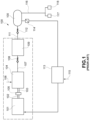
- FIG. 1 A system for generating compressed air according to the prior art is illustrated in Figure 1 .
- Such system for generating compressed air 100 comprises a motor 101 whose motor shaft 102 supplies a driving torque to a motor shaft 103 of a compressor 104 through an elastic coupling 105.
- the compressor 104 draws air at atmospheric pressure, compresses it and, through a pneumatic connection 107 and a non-return valve 108, supplies a dryer unit 109.
- the dryer unit 109 has the purpose of removing the liquid component and the vapor of the water derived from the compression of humid air and supplying dried air to a main reservoir 110 through a second duct 111 and a second non-return valve 112.
- a control unit 113 receives an electrical power supply 115 and measures a pressure in the main reservoir 110 by means of a pressure transducer 114.
- control unit 113 supplies electrical power to the electric motor 101.
- control unit 113 cuts off the electrical supply to the electric motor 101.
- the minimum value Pmin generally assumes values of between 6bar and 7 bar
- the maximum value Pmax generally assumes values of between 9bar and 10bar.
- the system for generating compressed air 100 is integrated inside an acoustically insulated metal structure provided with damping connections to the railway vehicle in order to reduce the noise emitted and the vibrations transmitted to a body of the railway vehicle, respectively.
- the compressed air stored in the main reservoir 110 is supplied to at least one user system 117, 118, such as, for example, the braking system, the suspension system, the toilets, the pantographs, the doors.
- Figure 2 illustrates a typical railway convoy 200 for carrying passengers.
- Two compressed air generation systems 201 and 202 corresponding to the compressed air generation system 100 of Figure 1 , supply compressed air to a main duct 202, which in turn supplies a main reservoir 204 through a non-return valve 215.
- various systems 205, 206, 207 such as for example the braking system, suspensions, toilets, draw compressed air for their operation.
- Two compressed air generation systems 201, 202 are considered necessary for redundancy reasons, i.e. to guarantee a permanent supply of compressed air even in the event of failure of one of the two compressed air generation systems 201, 202 during operational daily service.
- a control system 208 alternatively enables the two compressed air generation systems 201, 202 by means of the supply signals 209, 210, this disadvantageously meaning that one of the two compressed air generation systems 201, 202 is on average unused throughout service.
- each compressed air generation system 201, 202 often exceeds 500kg, disadvantageously requiring an unnecessary expenditure of energy to accelerate the mass thereof. This energy is then definitively lost during braking due to poor efficiency of the regenerative braking system or intrinsically dissipative mechanical friction braking.
- a single compressed air generation system may supply compressed air at full capacity at the total cost of two systems.
- WO 2018/185055 A1 discloses a method and a system for supplying compressed air to a vehicle as required. However, the above problems remain unsolved.
- An object of the present invention is to provide a method and a system for generating compressed air of at least one vehicle, in particular at least one railway vehicle, which reduces the weight and the cost compared to compressed air generation systems according to the prior art, while respecting the redundancy requirement.
- a method for generating compressed air of at least one vehicle, in particular a railway vehicle comprises the step of:
- the method further comprises the step of measuring a pressure value indicative of the internal pressure of a main reservoir 311 arranged to accumulate compressed air generated by said first compressor 303 and said second compressor 307.
- the pressure value inside said main reservoir 311 may assume over time a value included in a range of pressures.
- Such range of pressures includes a null value, a first predetermined pressure value Pmin (greater than said null value) and a second predetermined pressure value Pmax, greater than said first predetermined pressure value Pmin.
- step a) may comprise:
- step a) may comprise:
- step a) may selectively comprise:
- Such system for generating compressed air of at least one vehicle comprises an electric motor 301 arranged to generate a driving torque.
- the system for generating compressed air of at least one vehicle further comprises a first coupling means 304, arranged to selectively assume a first state in which it connects said electric motor 301 to said first compressor 303 or a second state in which it disconnects said motor electric motor 301 from said first compressor 303, and a second coupling means 308, arranged to selectively assume a first state in which it connects said electric motor 301 to said second compressor 307 or a second state in which it disconnects said electric motor 301 from said second compressor 307.
- the compressed air generation system of at least one vehicle further comprises a control means 320 arranged to control the transition between the first state and the second state, and vice versa, of said first coupling means 304 and the transition between the first state and the second state, and vice versa, of said second coupling means 308, so that said driving torque generated by said electric motor 301 is selectively supplied to the first compressor 303 or to the second compressor 307 or simultaneously to said first compressor 303 and to said second compressor 307.
- control means may be or comprise at least one of a control unit, a processor, a microprocessor, a controller, a microcontroller, an FPGA, a PLC, or the like.
- the compressed air generation system of at least one vehicle may comprise a main reservoir 311 arranged to store compressed air generated by said first compressor 303 and said second compressor 307, and a pressure sensor means arranged to measure a pressure value inside said main reservoir 311.
- the pressure value inside said main reservoir 311 may assume a pressure value included in a range of pressures.
- Such range of pressures includes a null value, a first predetermined pressure value Pmin (greater than said null value) and a second predetermined pressure value Pmax, greater than said first predetermined pressure value Pmin.
- the pressure sensor means may be or comprise, for example, a pressure sensor or a pressure measuring device, or the like.
- control means 320 may be arranged to:
- higher than said first predetermined pressure value Pmin for example, it may be understood a value equal to the second predetermined pressure value Pmax higher than said first predetermined pressure value Pmin, or a value between the first predetermined pressure value Pmin and the second predetermined pressure value Pmax.
- control means 320 may:
- control means 320 may be arranged to:
- the control means 320 may control the first coupling means 304 (e.g. a first electromechanical clutch) and the second coupling means 308 (e.g. a second electromechanical clutch 308) in their first state in which they transmit the driving torque of the electric motor 301 to the first compressor 303 and to the second compressor 307, and may control the electric motor 301 to rotate at a first speed V1, so as to generate a driving torque having a first torque value, suitable for bringing the pressure in the main reservoir 311 to the first predetermined pressure value Pmin as fast as possible.
- first coupling means 304 e.g. a first electromechanical clutch
- the second coupling means 308 e.g. a second electromechanical clutch 308
- control means 320 may be selectively arranged to:
- control means 320 may be arranged to selectively:
- the pressure in the main reservoir 311 may begin to drop towards the first predetermined pressure value Pmin due to a request for compressed air by one or more users 205, 206, 207.
- the control unit 320 may choose which of the first compressor 303 and the second compressor 307 is to be coupled to the electric motor 301, and may couple the selected compressor to the electric motor 301 by controlling the coupling means (e.g.
- the electromechanical clutch associated with the selected compressor, in its first state in which it transmits driving torque from the electric motor 301 to the selected compressor, and may for example control the electric motor 301 to rotate at a second speed V2, less than or equal to said first speed V1, i.e. V2 ⁇ V1.
- the other unselected compressor is not coupled to the electric motor 301 by controlling the coupling means (e.g. the electromechanical clutch) associated with the unselected compressor, in its second state in which it does not transmit driving torque from the electric motor 301 to the unselected compressor.
- the preselected compressor may be any one between the first compressor 303 and the second compressor 307.
- control means 320 may be arranged to measure a first overall activation time of said first compressor 303 and to measure a second overall activation time of said second compressor 307.
- said control means 320 may be arranged to:
- control means 320 may be arranged to:
- said control means 320 may be arranged to:
- control means 320 may be arranged to:
- the control means 320 may count the cumulative usage time of the first compressor and the second compressor and choose to connect the compressor with the shortest usage time to the electric motor, in order to better equalize the consumption of the components of the first compressor and the second compressor, so as to reach the deadline of the maintenance cycle at the same time.
- control means 320 may be arranged to measure a first overall activation time of said first compressor 303 and to measure a second overall activation time of said second compressor 307.
- the control means 320 may be arranged to:
- said control means 320 may be arranged to:
- control means 320 may be arranged to:
- said control means 320 may be arranged to:
- control means 320 may be arranged to:
- the control unit 320 may re-count the cumulative usage time of the first compressor and second compressor and, for example at the start of the operating day, the control unit 320 may choose the compressor that has the shortest cumulative usage time and, when it is necessary to bring the pressure in the main reservoir from the first predetermined pressure value Pmin to the second predetermined pressure value Pmax, it may use it for a predetermined period, inhibiting the other compressor in such predetermined period (e.g. all day).
- said control unit may be arranged to define first time-intervals in which activation of the first compressor 303 is prevented and second time-intervals in which activation of second compressor 307 is prevented. Said first time-intervals and said second time-intervals may be alternated to each other over time.
- said control means 320 may be arranged to:
- control means 320 may be arranged to:
- control means 320 may be arranged to:
- control means 320 may be arranged to:
- the control unit 320 may alternatively use the two compressors at alternate regular periods, for example non-exclusive on alternate days. In this way, the selected compressor may be kept for a period, always at temperature to limit the formation of condensation inside the compressor due to excessive cooling and the wear of the first compressor and the second compressor is balanced.
- control means 320 may be arranged to:
- control means 320 may be arranged to:
- control means 320 may be arranged to:
- the control means 320 may turn off the electric motor 301 and control the first coupling means 304 (e.g. the first electromechanical clutch) and the second coupling means 308 (e.g. the second electromechanical clutch 308) in their second state in which they do not transmit driving torque from the electric motor 301 to the first compressor 303 and the second compressor 307, respectively.
- the first coupling means 304 e.g. the first electromechanical clutch
- the second coupling means 308 e.g. the second electromechanical clutch 308
- control means 320 may be arranged to:
- the compressed air generation system of at least one vehicle may comprise a first air dryer means 310 and a second air dryer means 313.
- the first air dryer means 310 may be arranged to receive the compressed air generated by the first compressor 303 and generate first dried compressed air to be supplied to said main reservoir 311.
- the second air dryer means 313 may be arranged to receive the compressed air generated by the second compressor 307 and generate second dried compressed air to be supplied to said main reservoir 311.
- the first compressor 303 may feed a first dryer 310, which in turn may feed the main reservoir 311 through a non-return valve 312.
- the second compressor 307 may feed a second dryer 313, which in turn feeds the main reservoir 311 through a non-return valve 314.
- the compressed air generation system of at least one vehicle may comprise only one air dryer means.
- the air dryer means may be arranged to receive compressed air generated by the first compressor 303, receive compressed air generated by the second compressor 307 and generate dried compressed air to be supplied to said main reservoir 311.
- the first compressor 303 and the second compressor 307 may supply compressed air to a single dryer 310, for example through two non-return valves 312, 314, respectively.
- the electric motor 301 may comprise a first drive shaft 302 arranged to transmit driving torque to a first compressor 303 through the first coupling means 304 and a first mechanical coupling 305, and a second drive shaft 306, arranged to be integral with the said first drive shaft 302 and to transmit the driving torque to the second compressor 307 through the second coupling means 308 and a second mechanical coupling 309.
- the electric motor 301 may comprise a drive shaft 501 on which the first coupling means 304 and the second coupling means 308 are arranged to be bound.
- the compressed air generation system of at least one vehicle may comprise a first pulley 505 and a second pulley 507.
- the first pulley 505 may be arranged to be mechanically bound to a shaft 504 of the first compressor 303
- the second pulley 507 may be arranged to be mechanically bound to a shaft 506 of a second compressor 307.
- the first coupling means 502, 304 may be arranged to transmit driving torque to the first pulley 505 by at least one drive belt 508, and the second coupling means 503, 308 may be arranged to transmit driving torque to the second pulley 507 by at least one drive belt 509.
- the first coupling means 304 may be an electromechanical clutch.
- the second coupling means 308 may also be an electromechanical clutch.
- the first predetermined pressure value Pmin may generally assume values of between 6bar and 7 bar
- the second predetermined pressure value Pmax may generally assume values of between 9bar and 10bar.
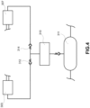
- a compressed air generation system 300 may comprise an electric motor 301 having a first drive shaft 302 for transmitting driving torque to a first compressor 303 through a first coupling means 304, such as for example a first electromechanical clutch, and a first mechanical coupling 305.
- a first coupling means 304 such as for example a first electromechanical clutch, and a first mechanical coupling 305.
- the electric motor 301 may be provided with a second drive shaft 306, integral with the first drive shaft 302, for transmitting driving torque to a second compressor 307 through a second coupling means 308, such as for example a second electromechanical clutch, and a second mechanical coupling 309.
- a second coupling means 308 such as for example a second electromechanical clutch, and a second mechanical coupling 309.
- the first compressor 303 may feed a first dryer means 310, for example a first dryer, which in turn may feed the main reservoir 311 through a non-return valve 312.
- the second compressor 307 may feed a second dryer means 313, for example a second dryer, which in turn may feed the main reservoir 311 through a non-return valve 314.
- the control means 320 for example a control unit, may be arranged to:
- the pressure sensor means 32 for example a pressure transducer 321, may measure the pressure inside the main reservoir 311 and send its value 322 to the control unit 320.
- the electric motor 301 may have a drive shaft 501 on which the first coupling means 502, for example a first electromechanical clutch, and a second coupling means, for example a second electromechanical clutch 503, are mechanically bound.
- Both coupling means 502, 503 may have the peripheral shape of a pulley for driving at least one drive belt.
- a first pulley 505 may be mechanically bound to a shaft 504 of the first compressor 303, and a second pulley 507 may be mechanically bound to a shaft 506 of a second compressor 307.
- the first coupling means 502 may transmit driving torque to the first pulley 505 by means of at least one drive belt 508.
- the second coupling means 503 may transmit driving torque to the second pulley 507 by means of at least one drive belt 509.
- the control means 320 for example a control unit 320, may be arranged to:
- At least one vehicle for example railway vehicle
- a plurality of railway vehicles connected to each other to form a convoy, for example a railway convoy.
- a vehicle referred to herein may be a locomotive or a wagon, and a route/section may include rails on which the wheels of the locomotive roll.
- the embodiments described herein are not intended to be limited to vehicles on tracks.
- the vehicle may be a car, a truck (for example a highway semi-trailer truck, a mining truck, a truck for transporting timber or the like) or the like, and the route may be a road or a trail.
- a convoy may comprise a plurality of such vehicles connected or associated with each other.
Landscapes
- Engineering & Computer Science (AREA)
- Mechanical Engineering (AREA)
- Transportation (AREA)
- General Engineering & Computer Science (AREA)
- Control Of Positive-Displacement Pumps (AREA)
- Compressors, Vaccum Pumps And Other Relevant Systems (AREA)
- Valves And Accessory Devices For Braking Systems (AREA)
Claims (19)
- Verfahren zur Erzeugung von Druckluft von mindestens einem Fahrzeug, insbesondere mindestens einem Schienenfahrzeug, umfassend den folgenden Schritt:a) Verbinden selektiv eines ersten Kompressors (303) oder eines zweiten Kompressors (307) oder gleichzeitig des ersten Kompressors (303) und des zweiten Kompressors (307) mit einem Elektromotor (301), der eingerichtet ist, ein Antriebsmoment zu erzeugen.
- Verfahren zur Erzeugung von Druckluft von mindestens einem Fahrzeug nach Anspruch 1, umfassend den folgenden Schritt:- Messen eines Druckwerts, der den Innendruck eines Hauptbehälters (311) angibt, der eingerichtet ist, Druckluft, die von dem ersten Kompressor (303) und dem zweiten Kompressor (307) erzeugt wird, zu speichern, wobei der Druckwert innerhalb des Hauptbehälters (311) eingerichtet ist, im Laufe der Zeit einen Wert innerhalb eines Druckbereichs einzunehmen, der umfasst:- einen Nullwert;- einen ersten vorbestimmten Druckwert (Pmin);- einen zweiten vorbestimmten Druckwert (Pmax), der größer als der erste vorbestimmte Druckwert (Pmin) ist.
- Verfahren zur Erzeugung von Druckluft von mindestens einem Fahrzeug nach Anspruch 2, wobei es, wenn der Druckwert in dem Hauptbehälter (311) kleiner als der erste vorbestimmte Druckwert (Pmin), Schritt a) ist, umfasst:- Verbinden des ersten Kompressors (303) mit dem Elektromotor (301);- Verbinden des zweiten Kompressors (307) mit dem Elektromotor (301);- Halten des ersten Kompressors (303) und des zweiten Kompressors (307) in Verbindung mit dem Elektromotor (301), bis der Druckwert in dem Hauptbehälter (311) den ersten vorbestimmten Druckwert (Pmin) erreicht oder überschreitet;und/oder
wenn der Druckwert in dem Hauptbehälter (311) gleich oder größer als der zweite vorbestimmte Druckwert (Pmax), Schritt a) ist, umfasst:- Trennen oder Halten des ersten Kompressors (303) getrennt von dem Elektromotor (301);- Trennen oder Halten des zweiten Kompressors (307) getrennt von dem Elektromotor (301);- Halten des ersten Kompressors (303) und des zweiten Kompressors (307) getrennt von dem Elektromotor (301), bis der Druckwert in dem Hauptbehälter (311) gleich oder kleiner als der erste vorbestimmte Druckwert (Pmin) ist. - Verfahren zur Erzeugung von Druckluft von mindestens einem Fahrzeug nach einem der Ansprüche 2 oder 3, wobei es, wenn der Druckwert in dem Hauptbehälter (311) gleich dem ersten vorbestimmten Druckwert (Pmin) ist oder zwischen dem ersten vorbestimmten Druckwert (Pmin) und dem zweiten vorbestimmten Druckwert (Pmax) liegt, Schritt a) selektiv umfasst:- Verbinden oder Halten des zweiten Kompressors (307) verbunden mit dem Elektromotor (301);- Trennen oder Halten des ersten Kompressors (303) getrennt von dem Elektromotor (301);- Halten des zweiten Kompressors (307) in Verbindung mit dem Elektromotor (301) und Halten des ersten Kompressors (303) getrennt von dem Elektromotor (301), bis der Druckwert in dem Hauptbehälter (311) gleich oder größer als der zweite vorbestimmte Druckwert (Pmax) ist;
oder,- Trennen oder Halten des zweiten Kompressors (307) getrennt von dem Elektromotor (301);- Verbinden oder Halten des ersten Kompressors (303) verbunden mit dem Elektromotor (301);- Halten des zweiten Kompressors (307) getrennt von dem Elektromotor (301) und Halten des ersten Kompressors (303) verbunden mit dem Elektromotor (301), bis der Druckwert in dem Hauptbehälter (311) gleich oder größer als der zweite vorbestimmte Druckwert (Pmax) ist. - System zur Erzeugung von Druckluft von mindestens einem Fahrzeug, insbesondere mindestens einem Schienenfahrzeug, umfassend:- einen Elektromotor (301), der eingerichtet ist, ein Antriebsmoment zu erzeugen;- ein erstes Kupplungsmittel (304), das eingerichtet ist, selektiv einen ersten Zustand, in dem es den Elektromotor (301) mit dem ersten Kompressor (303) verbindet, oder einen zweiten Zustand, in dem es den Elektromotor (301) von dem ersten Kompressor (303) trennt, einzunehmen;- ein zweites Kupplungsmittel (308), das eingerichtet ist, selektiv einen ersten Zustand, in dem es den Elektromotor (301) mit dem zweiten Kompressor (307) verbindet, oder einen zweiten Zustand, in dem es den Elektromotor (301) von dem zweiten Kompressor (307) trennt, einzunehmen;- ein Steuermittel (320), das eingerichtet ist, den Übergang zwischen dem ersten Zustand und dem zweiten Zustand und umgekehrt des ersten Kupplungsmittels (304) sowie den Übergang zwischen dem ersten Zustand und dem zweiten Zustand und umgekehrt des zweiten Kupplungsmittels (308) zu steuern, sodass das Antriebsmoment, das von dem Elektromotor (301) erzeugt wird, selektiv dem ersten Kompressor (303) oder dem zweiten Kompressor (307) oder gleichzeitig dem ersten Kompressor (303) und dem zweiten Kompressor (307) zugeführt wird.
- System zur Erzeugung von Druckluft von mindestens einem Fahrzeug nach Anspruch 5, umfassend:- einen Hauptbehälter (311), der eingerichtet ist, die Druckluft, die von dem ersten Kompressor (303) und dem zweiten Kompressor (307) erzeugt wird, zu speichern; und- ein Drucksensormittel, das eingerichtet ist, einen Druckwert innerhalb des Hauptbehälters (311) zu messen;wobei der Druckwert innerhalb des Hauptbehälters (311) eingerichtet ist, im Laufe der Zeit einen Wert innerhalb eines Druckbereichs einzunehmen, der umfasst: einen Nullwert, einen ersten vorbestimmten Druckwert (Pmin), der größer als der Nullwert ist, und einen zweiten vorbestimmten Druckwert (Pmax), der größer als der erste vorbestimmte Druckwert (Pmin) ist.
- System zur Erzeugung von Druckluft von mindestens einem Fahrzeug nach Anspruch 6, wobei es, wenn der Druckwert, der durch das Drucksensormittel gemessen wird, kleiner als der erste vorbestimmte Druckwert (Pmin) ist, das Steuermittel (320) eingerichtet ist, um:- das erste Kupplungsmittel (304) zu steuern, sodass es sich in seinem ersten Zustand befindet, in dem es den Elektromotor (301) mit dem ersten Kompressor (303) verbindet;- das zweite Kupplungsmittel (308) zu steuern, sodass es sich in seinem ersten Zustand befindet, in dem es den Elektromotor (301) mit dem zweiten Kompressor (307) verbindet;- das erste Kupplungsmittel (304) in seinem ersten Zustand und das zweite Kupplungsmittel (308) in seinem ersten Zustand zu halten, bis der Druckwert, der durch das Drucksensormittel gemessen wird, den ersten vorbestimmten Druckwert (Pmin) erreicht.
- System zur Erzeugung von Druckluft von mindestens einem Fahrzeug nach Anspruch 6 oder 7, wobei, wenn der Druckwert, der durch das Drucksensormittel gemessen wird, gleich dem ersten vorbestimmten Druckwert (Pmin) ist oder zwischen dem ersten vorbestimmten Druckwert (Pmin) und dem zweiten vorbestimmten Druckwert (Pmax) liegt, das Steuermittel (320) eingerichtet ist, selektiv um:- das zweite Kupplungsmittel (308) zu steuern, sodass es sich in seinem ersten Zustand befindet, in dem es den Elektromotor (301) mit dem zweiten Kompressor (307) verbindet, und das erste Kupplungsmittel (304) zu steuern, sodass es sich in seinem zweiten Zustand befindet, in dem es den Elektromotor (301) von dem ersten Kompressor (303) trennt;- das zweite Kupplungsmittel (308) in seinem ersten Zustand und das erste Kupplungsmittel (304) in seinem zweiten Zustand zu halten, bis der Druckwert, der durch das Drucksensormittel gemessen wird, gleich oder größer als der zweite vorbestimmte Druckwert (Pmax) ist, der größer als der erste vorbestimmte Druckwert (Pmin) ist;
oder,- das erste Kupplungsmittel (304) zu steuern, sodass es sich in seinem ersten Zustand befindet, in dem es den Elektromotor (301) mit dem ersten Kompressor (303) verbindet, und das zweite Kupplungsmittel (308) zu steuern, sodass es sich in seinem zweiten Zustand befindet, in dem es den Elektromotor (301) von dem zweiten Kompressor (307) trennt;- das erste Kupplungsmittel (304) in seinem ersten Zustand und das zweite Kupplungsmittel (308) in seinem zweiten Zustand zu halten, bis der Druckwert, der durch das Drucksensormittel gemessen wird, gleich oder größer als der zweite vorbestimmte Druckwert (Pmax) ist, der größer als der erste vorbestimmte Druckwert (Pmin) ist. - System zur Erzeugung von Druckluft von mindestens einem Fahrzeug nach Anspruch 6 oder 7, wobei das Steuermittel (320) eingerichtet ist, eine erste Gesamtaktivierungszeit des ersten Kompressors (303) zu messen und eine zweite Gesamtaktivierungszeit des zweiten Kompressors (307) zu messen;wobei, wenn der Druckwert, der durch das Drucksensormittel gemessen wird, gleich dem ersten vorbestimmten Druckwert (Pmin) ist oder zwischen dem ersten vorbestimmten Druckwert (Pmin) und dem zweiten vorbestimmten Druckwert (Pmax) liegt, und die erste Gesamtaktivierungszeit des ersten Kompressors (303) größer als die zweite Gesamtaktivierungszeit des zweiten Kompressors (307) ist, das Steuermittel (320) eingerichtet ist, um:- das zweite Kupplungsmittel (308) zu steuern, sodass es sich in seinem ersten Zustand befindet, in dem es den Elektromotor (301) mit dem zweiten Kompressor (307) verbindet, und das erste Kupplungsmittel (304) zu steuern, sodass es sich in seinem zweiten Zustand befindet, in dem es den Elektromotor (301) von dem ersten Kompressor (303) trennt;- das zweite Kupplungsmittel (308) in seinem ersten Zustand und das erste Kupplungsmittel (304) in seinem zweiten Zustand zu halten, bis der Druckwert, der durch das Drucksensormittel gemessen wird, gleich oder größer als der zweite vorbestimmte Druckwert (Pmax) ist, der größer als der erste vorbestimmte Druckwert (Pmin) ist;wobei, wenn der Druckwert, der durch das Drucksensormittel gemessen wird, gleich dem ersten vorbestimmten Druckwert (Pmin) ist oder zwischen dem ersten vorbestimmten Druckwert (Pmin) und dem zweiten vorbestimmten Druckwert (Pmax) liegt, und die erste Gesamtaktivierungszeit des ersten Kompressors (303) kürzer als die zweite Gesamtaktivierungszeit des zweiten Kompressors (307) ist, das Steuermittel (320) eingerichtet ist, um:- das erste Kupplungsmittel (304) zu steuern, sodass es sich in seinem ersten Zustand befindet, in dem es den Elektromotor (301) mit dem ersten Kompressor (303) verbindet, und das zweite Kupplungsmittel (308) zu steuern, sodass es sich in seinem zweiten Zustand befindet, in dem es den Elektromotor (301) von dem zweiten Kompressor (307) trennt;- das erste Kupplungsmittel (304) in seinem ersten Zustand und das zweite Kupplungsmittel (308) in seinem zweiten Zustand zu halten, bis der Druckwert, der durch das Drucksensormittel gemessen wird, gleich oder größer als der zweite vorbestimmte Druckwert (Pmax) ist, der größer als der erste vorbestimmte Druckwert (Pmin) ist.
- System zur Erzeugung von Druckluft von mindestens einem Fahrzeug nach Anspruch 6 oder 7, wobei das Steuermittel (320) eingerichtet ist, eine erste Gesamtaktivierungszeit des ersten Kompressors (303) zu messen und eine zweite Gesamtaktivierungszeit des zweiten Kompressors (307) zu messen;
wobei das Steuermittel (320) eingerichtet ist, um;- wenn die erste Gesamtaktivierungszeit des ersten Kompressors (303) größer als die zweite Gesamtaktivierungszeit des zweiten Kompressors (307) ist, die Aktivierung des ersten Kompressors (303) für eine erste Sperrungszeitspanne zu verhindern;- wenn die erste Gesamtaktivierungszeit des ersten Kompressors (303) kürzer als die zweite Gesamtaktivierungszeit des zweiten Kompressors (307) ist, die Aktivierung des zweiten Kompressors (307) für eine zweite Sperrungszeitspanne zu verhindern. - System zur Erzeugung von Druckluft von mindestens einem Fahrzeug nach Anspruch 10, wobei in der ersten Sperrungszeitspanne, wenn der Druckwert, der durch das Drucksensormittel gemessen wird, gleich dem ersten vorbestimmten Druckwert (Pmin) ist oder zwischen dem ersten vorbestimmten Druckwert (Pmin) und dem zweiten vorbestimmten Druckwert (Pmax) liegt, das Steuermittel (320) eingerichtet ist, um:- das zweite Kupplungsmittel (308) zu steuern, sodass es sich in seinem ersten Zustand befindet, in dem es den Elektromotor (301) mit dem zweiten Kompressor (307) verbindet, und das erste Kupplungsmittel (304) zu steuern, sodass es sich in seinem zweiten Zustand befindet, in dem es den Elektromotor (301) von dem ersten Kompressor (303) trennt;- das zweite Kupplungsmittel (308) in seinem ersten Zustand und das erste Kupplungsmittel (304) in seinem zweiten Zustand zu halten, bis der Druckwert, der durch das Drucksensormittel gemessen wird, gleich oder größer als der zweite vorbestimmte Druckwert (Pmax) ist, der größer als der erste vorbestimmte Druckwert (Pmin) ist;
wobei, in der zweiten Sperrungszeitspanne, wenn der Druckwert, der durch das Drucksensormittel gemessen wird, gleich dem ersten vorbestimmten Druckwert (Pmin) ist oder zwischen dem ersten vorbestimmten Druckwert (Pmin) und dem zweiten vorbestimmten Druckwert (Pmax) liegt, das Steuermittel (320) eingerichtet ist, um:- das erste Kupplungsmittel (304) zu steuern, sodass es sich in seinem ersten Zustand befindet, in dem es den Elektromotor (301) mit dem ersten Kompressor (303) verbindet, und das zweite Kupplungsmittel (308) zu steuern, sodass es sich in seinem zweiten Zustand befindet, in dem es den Elektromotor (301) von dem zweiten Kompressor (307) trennt;- das erste Kupplungsmittel (304) in seinem ersten Zustand und das zweite Kupplungsmittel (308) in seinem zweiten Zustand zu halten, bis der Druckwert, der durch das Drucksensormittel gemessen wird, gleich oder größer als der zweite vorbestimmte Druckwert (Pmax) ist, der größer als der erste vorbestimmte Druckwert (Pmin) ist. - System zur Erzeugung von Druckluft von mindestens einem Fahrzeug nach Anspruch 6 oder 7, wobei die Steuereinheit eingerichtet ist, erste Zeitintervalle zu definieren, in denen die Aktivierung des ersten Kompressors (303) verhindert wird, und zweite Zeitintervalle, in denen die Aktivierung des zweiten Kompressors (307) verhindert wird, wobei die ersten Zeitintervalle und die zweiten Zeitintervalle zeitlich abwechselnd auftreten;wobei, wenn in einem der ersten Zeitintervalle der Druckwert, der durch das Drucksensormittel gemessen wird, gleich dem ersten vorbestimmten Druckwert (Pmin) ist oder zwischen dem ersten vorbestimmten Druckwert (Pmin) und dem zweiten vorbestimmten Druckwert (Pmax) liegt, das Steuermittel (320) eingerichtet ist, um:- das zweite Kupplungsmittel (308) zu steuern, sodass es sich in seinem ersten Zustand befindet, in dem es den Elektromotor (301) mit dem zweiten Kompressor (307) verbindet, und das erste Kupplungsmittel (304) zu steuern, sodass es sich in seinem zweiten Zustand befindet, in dem es den Elektromotor (301) von dem ersten Kompressor (303) trennt;- das zweite Kupplungsmittel (308) in seinem ersten Zustand und das erste Kupplungsmittel (304) in seinem zweiten Zustand zu halten, bis der Druckwert, der durch das Drucksensormittel gemessen wird, gleich oder größer als der zweite vorbestimmte Druckwert (Pmax) ist, der größer als der erste vorbestimmte Druckwert (Pmin) ist;wobei, wenn in einem der zweiten Zeitintervalle der Druckwert, der durch das Drucksensormittel gemessen wird, gleich dem ersten vorbestimmten Druckwert (Pmin) ist oder zwischen dem ersten vorbestimmten Druckwert (Pmin) und dem zweiten vorbestimmten Druckwert (Pmax) liegt, das Steuermittel (320) eingerichtet ist, um:- das erste Kupplungsmittel (304) zu steuern, sodass es sich in seinem ersten Zustand befindet, in dem es den Elektromotor (301) mit dem ersten Kompressor (303) verbindet, und das zweite Kupplungsmittel (308) zu steuern, sodass es sich in seinem zweiten Zustand befindet, in dem es den Elektromotor (301) von dem zweiten Kompressor (307) trennt;- das erste Kupplungsmittel (304) in seinem ersten Zustand und das zweite Kupplungsmittel (308) in seinem zweiten Zustand zu halten, bis der Druckwert, der durch das Drucksensormittel gemessen wird, gleich oder größer als der zweite vorbestimmte Druckwert (Pmax) ist, der größer als der erste vorbestimmte Druckwert (Pmin) ist.
- System zur Erzeugung von Druckluft von mindestens einem Fahrzeug nach einem der Ansprüche 6 bis 12, wobei, wenn der Druckwert, der durch das Drucksensormittel gemessen wird, gleich oder größer als der zweite vorbestimmte Druckwert (Pmax) ist, der größer als der erste vorbestimmte Druckwert (Pmin) ist, das Steuermittel (320) eingerichtet ist, um:- das erste Kupplungsmittel (304) zu steuern, sodass es sich in seinem zweiten Zustand befindet, in dem es den Elektromotor (301) von dem ersten Kompressor (303) trennt;- das zweite Kupplungsmittel (308) zu steuern, sodass es sich in seinem zweiten Zustand befindet, in dem es den Elektromotor (301) von dem zweiten Kompressor (307) trennt;- das erste Kupplungsmittel (304) in seinem zweiten Zustand und das zweite Kupplungsmittel (308) in seinem zweiten Zustand zu halten, bis der Druckwert, der durch das Drucksensormittel gemessen wird, gleich oder kleiner als der erste vorbestimmte Druckwert (Pmin) ist.
- System zur Erzeugung von Druckluft von mindestens einem Fahrzeug nach Anspruch 13, wobei, wenn der Druckwert, der durch das Drucksensormittel gemessen wird, gleich oder größer als der zweite vorbestimmte Druckwert (Pmax) ist, das Steuermittel (320) eingerichtet ist, um:- den Elektromotor (301) anzusteuern, sodass ein Antriebsmoment mit Nullwert erzeugt wird.
- System zur Erzeugung von Druckluft von mindestens einem Fahrzeug nach einem der Ansprüche 6 bis 14, wobei, wenn der Druckwert, der durch das Drucksensormittel gemessen wird, kleiner als der erste vorbestimmte Druckwert (Pmin) ist, das Steuermittel (320) eingerichtet ist, um:- den Elektromotor (301) anzusteuern, sodass ein Antriebsmoment mit einem ersten Drehmomentwert erzeugt wird.
- System zur Erzeugung von Druckluft von mindestens einem Fahrzeug nach Anspruch 15, wobei, wenn der Druckwert, der durch das Drucksensormittel gemessen wird, zwischen dem ersten vorbestimmten Druckwert (Pmin) und dem zweiten vorbestimmten Druckwert (Pmax) liegt, der größer als der erste vorbestimmte Druckwert (Pmin) ist, das Steuermittel (320) eingerichtet ist, um:- den Elektromotor (301) anzusteuern, sodass ein Antriebsmoment aufweisend einen zweiten Drehmomentwert erzeugt wird, der kleiner oder gleich dem ersten Drehmomentwert ist.
- System zur Erzeugung von Druckluft von mindestens einem Fahrzeug nach einem der Ansprüche 5 bis 16, umfassend ein Lufttrocknungsmittel;
wobei das Lufttrocknungsmittel eingerichtet ist, Druckluft, die von dem ersten Kompressor (303) erzeugt wird, zu empfangen, und Druckluft, die von dem zweiten Kompressor (307) erzeugt wird, zu empfangen, und getrocknete Druckluft zu erzeugen, die dem Hauptbehälter (311) zugeführt wird. - System zur Erzeugung von Druckluft von mindestens einem Fahrzeug nach einem der Ansprüche 5 bis 17, wobei der Elektromotor (301) umfasst:- eine erste Antriebswelle (302), die eingerichtet ist, ein Antriebsmoment über das erste Kupplungsmittel (304) und eine erste mechanische Kupplung (305) auf den ersten Kompressor (303) zu übertragen;- eine zweite Antriebswelle (306), die eingerichtet ist, mit der ersten Antriebswelle (302) einstückig ausgebildet zu werden und das Antriebsmoment über das zweite Kupplungsmittel (308) und eine zweite mechanische Kupplung (309) auf den zweiten Kompressor (307) zu übertragen;oder,wobei der Elektromotor (301) eine Antriebswelle (501) umfasst, an der das erste Kupplungsmittel (304) und das zweite Kupplungsmittel (308) eingerichtet sind, verbunden zu werden;wobei das Drucklufterzeugungssystem von mindestens einem Fahrzeug eine erste Riemenscheibe (505) und eine zweite Riemenscheibe (507) umfasst;wobei die erste Riemenscheibe (505) eingerichtet ist, mechanisch mit einer Welle (504) des ersten Kompressors (303) verbunden zu werden und die zweite Riemenscheibe (507) eingerichtet ist, mechanisch mit einer Welle (506) des zweiten Kompressors (307) verbunden zu werden;wobei das erste Kupplungsmittel (502, 304) eingerichtet ist, ein Antriebsmoment mittels mindestens eines Antriebsriemens (508) auf die erste Riemenscheibe (505) zu übertragen, und das zweite Kupplungsmittel (503, 308) eingerichtet ist, ein Antriebsmoment mittels mindestens eines Antriebsriemens (509) auf die zweite Riemenscheibe (507) zu übertragen.
- System zur Erzeugung von Druckluft von mindestens einem Fahrzeug nach einem der Ansprüche 5 bis 18, wobei das erste Kupplungsmittel (304) eine elektromechanische Kupplung ist und/oder das zweite Kupplungsmittel (308) eine elektromechanische Kupplung ist.
Applications Claiming Priority (3)
| Application Number | Priority Date | Filing Date | Title |
|---|---|---|---|
| IT102021000010484A IT202100010484A1 (it) | 2021-04-26 | 2021-04-26 | Sistema per la generazione di aria compressa di almeno un veicolo ferroviario |
| IT102021000011222A IT202100011222A1 (it) | 2021-05-03 | 2021-05-03 | Procedimento e sistema per la generazione di aria compressa di almeno un veicolo ferroviario |
| PCT/IB2022/053853 WO2022229837A1 (en) | 2021-04-26 | 2022-04-26 | Method and system for generating compressed air of at least one vehicle, particularly at least one railway vehicle |
Publications (3)
| Publication Number | Publication Date |
|---|---|
| EP4330111A1 EP4330111A1 (de) | 2024-03-06 |
| EP4330111B1 true EP4330111B1 (de) | 2025-06-18 |
| EP4330111B8 EP4330111B8 (de) | 2025-11-26 |
Family
ID=81940515
Family Applications (1)
| Application Number | Title | Priority Date | Filing Date |
|---|---|---|---|
| EP22727978.3A Active EP4330111B8 (de) | 2021-04-26 | 2022-04-26 | Verfahren und system zur erzeugung von druckluft von mindestens einem fahrzeug, insbesondere mindestens einem schienenfahrzeug |
Country Status (8)
| Country | Link |
|---|---|
| US (1) | US20240190407A1 (de) |
| EP (1) | EP4330111B8 (de) |
| JP (1) | JP2024518774A (de) |
| KR (1) | KR20240024052A (de) |
| BR (1) | BR112023022066A2 (de) |
| ES (1) | ES3040902T3 (de) |
| HU (1) | HUE072624T2 (de) |
| WO (1) | WO2022229837A1 (de) |
Family Cites Families (21)
| Publication number | Priority date | Publication date | Assignee | Title |
|---|---|---|---|---|
| US4506516A (en) * | 1984-04-06 | 1985-03-26 | Carrier Corporation | Refrigeration unit compressor control |
| JPS6132701U (ja) * | 1984-07-27 | 1986-02-27 | 株式会社日立製作所 | 空気圧式車両用パンタグラフ昇降制御装置 |
| US5123256A (en) * | 1991-05-07 | 1992-06-23 | American Standard Inc. | Method of compressor staging for a multi-compressor refrigeration system |
| US6419454B1 (en) * | 2000-06-14 | 2002-07-16 | Leo P. Christiansen | Air compressor control sequencer |
| DE102006041008A1 (de) * | 2006-08-31 | 2008-03-06 | Wabco Gmbh | Pneumatische Fahrzeugbremsanlage sowie Verfahren zum Steuern einer derartigen Bremsanlage |
| WO2008136796A1 (en) * | 2007-05-07 | 2008-11-13 | Carrier Corporation | Motor-compressor drive apparatus |
| WO2012067191A1 (ja) * | 2010-11-17 | 2012-05-24 | 本田技研工業株式会社 | 電動ブレーキアクチュエータ及び車両用ブレーキシステム |
| US9302682B2 (en) * | 2011-04-26 | 2016-04-05 | Norfolk Southern Corporation | Multiple compressor system and method for locomotives |
| US9469315B2 (en) * | 2013-05-22 | 2016-10-18 | Wabtec Holding Corp. | Thermally optimized railway vehicle brake system |
| DE102013212451B4 (de) * | 2013-06-27 | 2015-02-05 | Siemens Aktiengesellschaft | Schienenfahrzeug mit einer WC-Vorrichtung |
| DE102014108681B3 (de) * | 2014-04-11 | 2015-04-30 | Knorr-Bremse Systeme für Nutzfahrzeuge GmbH | Elektro-pneumatische Federspeicherbremseinrichtung eines Kraftfahrzeugs mit sprunghaftem Druckanstieg beim Bremslösen |
| DE102015115368A1 (de) * | 2015-09-11 | 2017-03-16 | Knorr-Bremse Systeme für Schienenfahrzeuge GmbH | Verfahren und Einrichtung zur Steuerung einer Lufttrocknereinheit einer Luftversorgungsanlage für die Haupt- und Hilfsluftversorgung, insbesondere für ein Schienenfahrzeug |
| DE102015015471A1 (de) * | 2015-11-28 | 2017-06-01 | Wabco Gmbh | Druckluft-Bremssystem für ein Fahrzeug und ein Verfahren zur Steuerung eines derartigen Druckluft-Bremssystems |
| DE102017107276A1 (de) * | 2017-04-05 | 2018-10-11 | Knorr-Bremse Systeme für Schienenfahrzeuge GmbH | Verfahren und Einrichtung für eine bedarfsgerechte Druckluftversorgung eines Fahrzeuges, insbesondere eines Schienenfahrzeuges |
| IT201800010349A1 (it) * | 2018-11-15 | 2020-05-15 | Faiveley Transport Italia Spa | Sistema di controllo elettronico della frenatura di un veicolo ferroviario |
| IT201900016490A1 (it) * | 2019-09-17 | 2021-03-17 | Faiveley Transport Italia Spa | Sistema per la generazione di aria compressa e per il condizionamento di aria, per un veicolo ferroviario |
| IT202000009205A1 (it) * | 2020-04-28 | 2021-10-28 | Faiveley Transport Italia Spa | Sistema di controllo per un convoglio ferroviario, particolarmente per il trasporto di merci |
| IT202000017020A1 (it) * | 2020-07-14 | 2022-01-14 | Faiveley Transport Italia Spa | Sistema di recupero di aria compressa rilasciata da sospensioni pneumatiche di almeno un veicolo ferroviario o di un convoglio ferroviario |
| CN117227781B (zh) * | 2023-09-01 | 2025-10-03 | 中车长春轨道客车股份有限公司 | 一种轨道车辆的供风控制系统、方法、设备及介质 |
| CA3276577A1 (en) * | 2024-06-10 | 2026-01-19 | Faiveley Transport Italia S.P.A. | Verification systems of the operation of a braking system for a vehicle, pressure measurement system for a braking system of a vehicle and vehicles |
| EP4674711A1 (de) * | 2024-07-05 | 2026-01-07 | Faiveley Transport Italia S.p.A. | Druckluftverteilsysteme, fahrzeuge und fahrzeuggruppe |
-
2022
- 2022-04-26 ES ES22727978T patent/ES3040902T3/es active Active
- 2022-04-26 WO PCT/IB2022/053853 patent/WO2022229837A1/en not_active Ceased
- 2022-04-26 BR BR112023022066A patent/BR112023022066A2/pt unknown
- 2022-04-26 HU HUE22727978A patent/HUE072624T2/hu unknown
- 2022-04-26 US US18/556,326 patent/US20240190407A1/en active Pending
- 2022-04-26 EP EP22727978.3A patent/EP4330111B8/de active Active
- 2022-04-26 JP JP2023565445A patent/JP2024518774A/ja active Pending
- 2022-04-26 KR KR1020237039774A patent/KR20240024052A/ko active Pending
Also Published As
| Publication number | Publication date |
|---|---|
| ES3040902T3 (en) | 2025-11-05 |
| WO2022229837A1 (en) | 2022-11-03 |
| KR20240024052A (ko) | 2024-02-23 |
| US20240190407A1 (en) | 2024-06-13 |
| EP4330111B8 (de) | 2025-11-26 |
| BR112023022066A2 (pt) | 2023-12-26 |
| HUE072624T2 (hu) | 2025-11-28 |
| JP2024518774A (ja) | 2024-05-02 |
| EP4330111A1 (de) | 2024-03-06 |
Similar Documents
| Publication | Publication Date | Title |
|---|---|---|
| EP4031431B1 (de) | System zur erzeugung von druckluft und zur klimatisierung für ein schienenfahrzeug | |
| US5178403A (en) | Electrical energy generating device for a wheeled semi-trailer | |
| US20100158702A1 (en) | Air compressor system | |
| US8674534B2 (en) | Managed pneumatic turbine power supply | |
| CN107683228A (zh) | 再生铁路制动系统 | |
| WO2012128770A1 (en) | Control system for vehicle equipped for regenerative braking | |
| JP5328625B2 (ja) | 付随車用アンチロックブレーキシステム | |
| WO2000006435A1 (en) | Railcar air motor driven generator | |
| CN112639289A (zh) | 用于混合动力车辆的双空气压缩机 | |
| JP2009119963A (ja) | 電気鉄道車両 | |
| US10414215B2 (en) | Mechanically driven tire pressure controlling device, in particular for a commercial vehicle trailer | |
| EP4330111B1 (de) | Verfahren und system zur erzeugung von druckluft von mindestens einem fahrzeug, insbesondere mindestens einem schienenfahrzeug | |
| CN103661481B (zh) | 单轴制动防滑控制系统 | |
| KR20260007124A (ko) | 압축 공기 분배 시스템, 차량 및 차량의 그룹 | |
| WO1997021558A1 (en) | A rail vehicle | |
| CN117597284A (zh) | 用于生成至少一辆车辆、特别是至少一辆铁路车辆的压缩空气的方法和系统 | |
| WO2023111972A1 (en) | Electromechanical actuator for a braking system of a vehicle, braking system and vehicle | |
| JP4410461B2 (ja) | 付随車用アンチロックブレーキシステム | |
| CN107415963A (zh) | 一种牵引和制动的配置和控制系统 | |
| US20240262317A1 (en) | Method for operating a pneumatic system, pneumatic system, vehicle | |
| IT202100010484A1 (it) | Sistema per la generazione di aria compressa di almeno un veicolo ferroviario | |
| EA044451B1 (ru) | Система выработки сжатого воздуха и кондиционирования воздуха для железнодорожного транспортного средства | |
| CN208469789U (zh) | 一种节能型电动空压机和转向油泵控制系统 | |
| JPS582521B2 (ja) | 車両用電空併用ブレ−キ装置 | |
| BR112022004643B1 (pt) | Sistema para a geração de ar comprimido e para condicionamento de ar |
Legal Events
| Date | Code | Title | Description |
|---|---|---|---|
| STAA | Information on the status of an ep patent application or granted ep patent |
Free format text: STATUS: UNKNOWN |
|
| STAA | Information on the status of an ep patent application or granted ep patent |
Free format text: STATUS: THE INTERNATIONAL PUBLICATION HAS BEEN MADE |
|
| PUAI | Public reference made under article 153(3) epc to a published international application that has entered the european phase |
Free format text: ORIGINAL CODE: 0009012 |
|
| STAA | Information on the status of an ep patent application or granted ep patent |
Free format text: STATUS: REQUEST FOR EXAMINATION WAS MADE |
|
| 17P | Request for examination filed |
Effective date: 20231123 |
|
| AK | Designated contracting states |
Kind code of ref document: A1 Designated state(s): AL AT BE BG CH CY CZ DE DK EE ES FI FR GB GR HR HU IE IS IT LI LT LU LV MC MK MT NL NO PL PT RO RS SE SI SK SM TR |
|
| DAV | Request for validation of the european patent (deleted) | ||
| DAX | Request for extension of the european patent (deleted) | ||
| P01 | Opt-out of the competence of the unified patent court (upc) registered |
Free format text: CASE NUMBER: APP_41534/2024 Effective date: 20240715 |
|
| GRAP | Despatch of communication of intention to grant a patent |
Free format text: ORIGINAL CODE: EPIDOSNIGR1 |
|
| STAA | Information on the status of an ep patent application or granted ep patent |
Free format text: STATUS: GRANT OF PATENT IS INTENDED |
|
| INTG | Intention to grant announced |
Effective date: 20250124 |
|
| GRAS | Grant fee paid |
Free format text: ORIGINAL CODE: EPIDOSNIGR3 |
|
| GRAA | (expected) grant |
Free format text: ORIGINAL CODE: 0009210 |
|
| STAA | Information on the status of an ep patent application or granted ep patent |
Free format text: STATUS: THE PATENT HAS BEEN GRANTED |
|
| AK | Designated contracting states |
Kind code of ref document: B1 Designated state(s): AL AT BE BG CH CY CZ DE DK EE ES FI FR GB GR HR HU IE IS IT LI LT LU LV MC MK MT NL NO PL PT RO RS SE SI SK SM TR |
|
| REG | Reference to a national code |
Ref country code: GB Ref legal event code: FG4D |
|
| REG | Reference to a national code |
Ref country code: CH Ref legal event code: EP |
|
| REG | Reference to a national code |
Ref country code: DE Ref legal event code: R096 Ref document number: 602022016119 Country of ref document: DE |
|
| REG | Reference to a national code |
Ref country code: CH Ref legal event code: EP |
|
| REG | Reference to a national code |
Ref country code: IE Ref legal event code: FG4D |
|
| PG25 | Lapsed in a contracting state [announced via postgrant information from national office to epo] |
Ref country code: FI Free format text: LAPSE BECAUSE OF FAILURE TO SUBMIT A TRANSLATION OF THE DESCRIPTION OR TO PAY THE FEE WITHIN THE PRESCRIBED TIME-LIMIT Effective date: 20250618 |
|
| REG | Reference to a national code |
Ref country code: LT Ref legal event code: MG9D |
|
| PG25 | Lapsed in a contracting state [announced via postgrant information from national office to epo] |
Ref country code: GR Free format text: LAPSE BECAUSE OF FAILURE TO SUBMIT A TRANSLATION OF THE DESCRIPTION OR TO PAY THE FEE WITHIN THE PRESCRIBED TIME-LIMIT Effective date: 20250919 Ref country code: NO Free format text: LAPSE BECAUSE OF FAILURE TO SUBMIT A TRANSLATION OF THE DESCRIPTION OR TO PAY THE FEE WITHIN THE PRESCRIBED TIME-LIMIT Effective date: 20250918 |
|
| PG25 | Lapsed in a contracting state [announced via postgrant information from national office to epo] |
Ref country code: BG Free format text: LAPSE BECAUSE OF FAILURE TO SUBMIT A TRANSLATION OF THE DESCRIPTION OR TO PAY THE FEE WITHIN THE PRESCRIBED TIME-LIMIT Effective date: 20250618 |
|
| PG25 | Lapsed in a contracting state [announced via postgrant information from national office to epo] |
Ref country code: HR Free format text: LAPSE BECAUSE OF FAILURE TO SUBMIT A TRANSLATION OF THE DESCRIPTION OR TO PAY THE FEE WITHIN THE PRESCRIBED TIME-LIMIT Effective date: 20250618 |
|
| PG25 | Lapsed in a contracting state [announced via postgrant information from national office to epo] |
Ref country code: RS Free format text: LAPSE BECAUSE OF FAILURE TO SUBMIT A TRANSLATION OF THE DESCRIPTION OR TO PAY THE FEE WITHIN THE PRESCRIBED TIME-LIMIT Effective date: 20250918 |
|
| REG | Reference to a national code |
Ref country code: CH Ref legal event code: Y10 Free format text: ST27 STATUS EVENT CODE: U-0-0-Y10-Y00 (AS PROVIDED BY THE NATIONAL OFFICE) Effective date: 20251022 Ref country code: NL Ref legal event code: MP Effective date: 20250618 |
|
| PG25 | Lapsed in a contracting state [announced via postgrant information from national office to epo] |
Ref country code: LV Free format text: LAPSE BECAUSE OF FAILURE TO SUBMIT A TRANSLATION OF THE DESCRIPTION OR TO PAY THE FEE WITHIN THE PRESCRIBED TIME-LIMIT Effective date: 20250618 |
|
| REG | Reference to a national code |
Ref country code: CH Ref legal event code: Q17 Free format text: ST27 STATUS EVENT CODE: U-0-0-Q10-Q17 (AS PROVIDED BY THE NATIONAL OFFICE) Effective date: 20251029 |
|
| REG | Reference to a national code |
Ref country code: ES Ref legal event code: FG2A Ref document number: 3040902 Country of ref document: ES Kind code of ref document: T3 Effective date: 20251105 |
|
| PG25 | Lapsed in a contracting state [announced via postgrant information from national office to epo] |
Ref country code: NL Free format text: LAPSE BECAUSE OF FAILURE TO SUBMIT A TRANSLATION OF THE DESCRIPTION OR TO PAY THE FEE WITHIN THE PRESCRIBED TIME-LIMIT Effective date: 20250618 |
|
| RIN2 | Information on inventor provided after grant (corrected) |
Inventor name: TIONE, ROBERTO Inventor name: BOUTEILLE, JEAN PHILIPPE Inventor name: ROSSINO, CORRADO |
|
| REG | Reference to a national code |
Ref country code: HU Ref legal event code: AG4A Ref document number: E072624 Country of ref document: HU |
|
| PG25 | Lapsed in a contracting state [announced via postgrant information from national office to epo] |
Ref country code: PT Free format text: LAPSE BECAUSE OF FAILURE TO SUBMIT A TRANSLATION OF THE DESCRIPTION OR TO PAY THE FEE WITHIN THE PRESCRIBED TIME-LIMIT Effective date: 20251020 |
|
| REG | Reference to a national code |
Ref country code: AT Ref legal event code: MK05 Ref document number: 1803954 Country of ref document: AT Kind code of ref document: T Effective date: 20250618 |
|
| PG25 | Lapsed in a contracting state [announced via postgrant information from national office to epo] |
Ref country code: IS Free format text: LAPSE BECAUSE OF FAILURE TO SUBMIT A TRANSLATION OF THE DESCRIPTION OR TO PAY THE FEE WITHIN THE PRESCRIBED TIME-LIMIT Effective date: 20251018 |
|
| PG25 | Lapsed in a contracting state [announced via postgrant information from national office to epo] |
Ref country code: AT Free format text: LAPSE BECAUSE OF FAILURE TO SUBMIT A TRANSLATION OF THE DESCRIPTION OR TO PAY THE FEE WITHIN THE PRESCRIBED TIME-LIMIT Effective date: 20250618 Ref country code: SM Free format text: LAPSE BECAUSE OF FAILURE TO SUBMIT A TRANSLATION OF THE DESCRIPTION OR TO PAY THE FEE WITHIN THE PRESCRIBED TIME-LIMIT Effective date: 20250618 |
|
| PG25 | Lapsed in a contracting state [announced via postgrant information from national office to epo] |
Ref country code: CZ Free format text: LAPSE BECAUSE OF FAILURE TO SUBMIT A TRANSLATION OF THE DESCRIPTION OR TO PAY THE FEE WITHIN THE PRESCRIBED TIME-LIMIT Effective date: 20250618 |
|
| PG25 | Lapsed in a contracting state [announced via postgrant information from national office to epo] |
Ref country code: PL Free format text: LAPSE BECAUSE OF FAILURE TO SUBMIT A TRANSLATION OF THE DESCRIPTION OR TO PAY THE FEE WITHIN THE PRESCRIBED TIME-LIMIT Effective date: 20250618 |
|
| PG25 | Lapsed in a contracting state [announced via postgrant information from national office to epo] |
Ref country code: SK Free format text: LAPSE BECAUSE OF FAILURE TO SUBMIT A TRANSLATION OF THE DESCRIPTION OR TO PAY THE FEE WITHIN THE PRESCRIBED TIME-LIMIT Effective date: 20250618 |
|
| PGFP | Annual fee paid to national office [announced via postgrant information from national office to epo] |
Ref country code: GB Payment date: 20260316 Year of fee payment: 5 |
|
| PG25 | Lapsed in a contracting state [announced via postgrant information from national office to epo] |
Ref country code: DK Free format text: LAPSE BECAUSE OF FAILURE TO SUBMIT A TRANSLATION OF THE DESCRIPTION OR TO PAY THE FEE WITHIN THE PRESCRIBED TIME-LIMIT Effective date: 20250618 |
|
| PLBE | No opposition filed within time limit |
Free format text: ORIGINAL CODE: 0009261 |
|
| STAA | Information on the status of an ep patent application or granted ep patent |
Free format text: STATUS: NO OPPOSITION FILED WITHIN TIME LIMIT |