EP4329959B1 - Drahtrichtmaschine und verfahren zum geraderichten von draht oder bandmaterial - Google Patents
Drahtrichtmaschine und verfahren zum geraderichten von draht oder bandmaterial Download PDFInfo
- Publication number
- EP4329959B1 EP4329959B1 EP22724254.2A EP22724254A EP4329959B1 EP 4329959 B1 EP4329959 B1 EP 4329959B1 EP 22724254 A EP22724254 A EP 22724254A EP 4329959 B1 EP4329959 B1 EP 4329959B1
- Authority
- EP
- European Patent Office
- Prior art keywords
- straightening
- wire
- axis
- aligning rollers
- model
- Prior art date
- Legal status (The legal status is an assumption and is not a legal conclusion. Google has not performed a legal analysis and makes no representation as to the accuracy of the status listed.)
- Active
Links
Images

Classifications
-
- B—PERFORMING OPERATIONS; TRANSPORTING
- B21—MECHANICAL METAL-WORKING WITHOUT ESSENTIALLY REMOVING MATERIAL; PUNCHING METAL
- B21F—WORKING OR PROCESSING OF METAL WIRE
- B21F1/00—Bending wire other than coiling; Straightening wire
- B21F1/02—Straightening
-
- B—PERFORMING OPERATIONS; TRANSPORTING
- B21—MECHANICAL METAL-WORKING WITHOUT ESSENTIALLY REMOVING MATERIAL; PUNCHING METAL
- B21F—WORKING OR PROCESSING OF METAL WIRE
- B21F1/00—Bending wire other than coiling; Straightening wire
- B21F1/02—Straightening
- B21F1/026—Straightening and cutting
-
- B—PERFORMING OPERATIONS; TRANSPORTING
- B21—MECHANICAL METAL-WORKING WITHOUT ESSENTIALLY REMOVING MATERIAL; PUNCHING METAL
- B21C—MANUFACTURE OF METAL SHEETS, WIRE, RODS, TUBES, PROFILES OR LIKE SEMI-MANUFACTURED PRODUCTS OTHERWISE THAN BY ROLLING; AUXILIARY OPERATIONS USED IN CONNECTION WITH METAL-WORKING WITHOUT ESSENTIALLY REMOVING MATERIAL
- B21C51/00—Measuring, gauging, indicating, counting, or marking devices specially adapted for use in the production or manipulation of material in accordance with subclasses B21B - B21F
-
- B—PERFORMING OPERATIONS; TRANSPORTING
- B21—MECHANICAL METAL-WORKING WITHOUT ESSENTIALLY REMOVING MATERIAL; PUNCHING METAL
- B21D—WORKING OR PROCESSING OF SHEET METAL OR METAL TUBES, RODS OR PROFILES WITHOUT ESSENTIALLY REMOVING MATERIAL; PUNCHING METAL
- B21D1/00—Straightening, restoring form or removing local distortions of sheet metal or specific articles made therefrom; Stretching sheet metal combined with rolling
- B21D1/02—Straightening, restoring form or removing local distortions of sheet metal or specific articles made therefrom; Stretching sheet metal combined with rolling by rollers
-
- B—PERFORMING OPERATIONS; TRANSPORTING
- B21—MECHANICAL METAL-WORKING WITHOUT ESSENTIALLY REMOVING MATERIAL; PUNCHING METAL
- B21D—WORKING OR PROCESSING OF SHEET METAL OR METAL TUBES, RODS OR PROFILES WITHOUT ESSENTIALLY REMOVING MATERIAL; PUNCHING METAL
- B21D3/00—Straightening or restoring form of metal rods, metal tubes, metal profiles, or specific articles made therefrom, whether or not in combination with sheet metal parts
- B21D3/02—Straightening or restoring form of metal rods, metal tubes, metal profiles, or specific articles made therefrom, whether or not in combination with sheet metal parts by rollers
- B21D3/05—Straightening or restoring form of metal rods, metal tubes, metal profiles, or specific articles made therefrom, whether or not in combination with sheet metal parts by rollers arranged on axes rectangular to the path of the work
Definitions
- the invention relates to a method for straightening wire or strip material by means of a dressing device with straightening rollers which act in an offset manner on opposite sides of the material passing through, some of which straightening rollers are automatically adjusted in such a way that the straightness requirements are met depending on a model which has been determined on the basis of input data of the material, the position of at least one straightening roller being continuously adapted on the basis of the said data which are recorded during the passage through the dressing device and which are representative of the straightness achieved, wherein within the model an X-axis lies in the direction of passage of the material, and a Y- and a Z-axis are perpendicular to one another and to the X-axis.
- the invention further relates to a wire straightening machine or a device for straightening wire or strip material with a dressing device with two rows of non-driven straightening rollers arranged longitudinally offset from one another, which during operation act on a material passing between the rows in order to straighten it, wherein some straightening rollers can be adjusted to the material in an automatically controlled manner depending on a model in such a way that the requirements for the straightness of the material emerging from the dressing device are met, wherein within the model an X-axis lies in the direction of flow of the material, and a Y- and a Z-axis are perpendicular to one another and to the X-axis.
- the WO 2020/172694 which forms the basis for the preamble of the independent claims, teaches a method and a device in which a wire can be straightened in an adjustable straightening device.
- a wire can be straightened in an adjustable straightening device.
- the wire temperature, the forces acting on the straightening rollers, or the deflection of the straightened free wire after leaving the straightening device are measured, entered into a model, and used to adjust the position of some straightening rollers to the wire.
- a disadvantage is that measuring the wire deflection requires a free wire, which cannot be directly processed by automated means.
- the WO 2015/144539 A1 discloses a method in which, within a test measurement, a relationship is determined between, among other things, forces acting on straightening rollers and "leveling material properties," such as the flatness of the material being straightened. A model is then created that allows the adjustment of straightening rollers within a leveling process based on current leveling material properties, but without measuring forces.
- a disadvantage is that the method only takes place within the scope of a test measurement.
- the invention has for its object to provide a closed control loop for an autonomous method for straightening material of unknown, variable curvature, wherein the wire end does not have to be free, wherein the straightening machine does not have to be built much longer than conventionally, and wherein no separate test measurement run has to be carried out.
- the wire or strip material passes through dressing devices one after the other, one dressing device having horizontally arranged straightening rollers and the other having vertically arranged straightening rollers.
- the material is cut to predetermined lengths behind the third sensor as seen in the direction of travel.
- the position of the material is measured behind all straightening rollers in the direction of travel by measuring the deviation of the material from the travel axis (the X-axis) in the direction of travel of the straightening rollers (the Y-axis) and perpendicular to these two axes (the Z-axis).
- Known optical measuring methods such as laser distance sensors (so-called laser scanners) or ultrasonic sensors, can be used for this purpose. It is conceivable that the position measurement is only performed at the beginning of the process for calibration purposes, while during operation, the measurement of the forces acting on the straightening rollers is sufficient to implement the method according to the invention.
- the invention further relates to a device for carrying out the method according to the invention.
- the invention in such a device consists in the fact that three sensors, spaced apart in the X direction, are arranged behind the dressing device for measuring the deflection of the material in the Z and Y directions, as seen in the direction of movement of the material. All measured values obtained can be fed to the model controlling the adjustment of the adjustable straightening rollers.
- a wire cutter is arranged behind the third sensor as seen in the direction of passage.
- the wire passes through two dressing devices one after the other, one dressing device having horizontally arranged straightening rollers and the other having vertically arranged straightening rollers.
- a second dressing device is arranged behind the third sensor with two rows of non-driven straightening rollers arranged longitudinally offset from one another, which, during operation, act on a material passing between the rows, wherein the second dressing device acts on the material offset by 90° from the first.
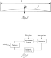
- Fig. 1 a training device with a wire running through it
- Fig. 2 the same training device with indicated measuring points
- Fig. 3 the graphical model of a wire deflection
- Fig. 4 shows a control loop as a block diagram.
- the training device of the Fig. 1 which is state of the art, has two horizontally offset rows of horizontal straightening rollers 3, 4, 6, 10. One row engages the wire material 1 to be straightened at the bottom, and the other row engages the wire to be straightened at the top.
- the wire material 1 to be straightened can also be strip material (not shown); in the following, the term wire material refers to the wire or strip material.
- the straightening rollers 3, 4, 6, 10 have no rotary drive; the wire as material 1 passes through the dressing device, which is moved by feed rollers (not shown) in the direction of arrow 2. Normally The wire passes through two dressing devices, each offset by 90°, one after the other, with one dressing device having horizontal straightening rollers and the other having vertical straightening rollers.
- the main working range of the invention covers wire diameters between approximately 4 mm and approximately 20 mm.
- the first two straightening rollers 3 of the Fig. 1 The lower rows have fixed axes of rotation.
- the lower straightening roller 4, which adjoins the lower straightening roller, can be individually adjusted to the passing material 1 by means of an adjusting device indicated at 5.
- the first three straightening rollers 6 of the upper row can be adjusted together to the material 1 and, for this purpose, are mounted on a common support 7, the height of which is adjustable by means of a lever 8 via a servomotor 9.
- the upper straightening roller 10, which adjoins the upper straightening rollers 6, can be individually adjusted to the material by means of an adjusting device indicated at 11.
- Fig. 2 It illustrates that three sensors 13, 14, 15 are installed downstream of the straightening rollers 3, 4, 6, and 10 in the straightening system. These sensors determine the position of the straightened wire in the Y-direction and in the Z-direction (not shown, as they are perpendicular to the paper plane). The three sensors 13, 14, and 15, spaced apart in the X-direction, determine the magnitude and direction of any remaining curvature.
- Fig. 3 shows the model, where the curvature b is related to a predetermined length l. l is a section along the X-axis that begins behind the straightening rollers of the dressage devices. It can also be located between two dressage devices offset or rotated by 90°. Ideally, all three sensors 13, 14, and 15 are located in section l.
- the wire has a curvature in the cut state (e.g. b/ l > 2 mm/m after Fig. 3 ), this is already apparent when the material 1 is clamped in front of the shears 16 or other elements of the straightening machine.
- the curvature is not as pronounced in the clamped state as it is after a cut by the shears 16.
- the behavior of the wire with curvature when clamped at both ends can be modeled.
- the curvature of the wire material 1 in the Y and Z directions is determined from the three position measurements.
- the curvature b from Fig. 3 becomes a vector in three-dimensional space. This vector is input into a nonlinear model, from which a prediction of the actual curvature, which would have to be compensated by a new adjustment of the straightening rollers 3, 4, 6, 10, is calculated.
- Fig. 4 The state estimation is achieved in the predictive control loop.
- the control itself is based on a model that maps the deviation in the leveling result to the required adjustment corrections of the leveling unit.
Landscapes
- Engineering & Computer Science (AREA)
- Mechanical Engineering (AREA)
- Wire Processing (AREA)
Description
- Die Erfindung betrifft ein Verfahren zum Geraderichten von Draht oder Bandmaterial mittels einer Dressurvorrichtung mit an gegenüberliegenden Seiten des durchlaufenden Materials versetzt angreifenden Richtrollen, von denen einige abhängig von einem Modell, das anhand von Eingangsdaten des Materials ermittelt worden ist, automatisch so angestellt werden, dass die Anforderungen an die Geradheit erfüllt werden, wobei die Stellung mindestens einer Richtrolle laufend adaptiert wird aufgrund der genannten, beim Durchlauf durch die Dressurvorrichtung erfassten Daten, welche für die erzielte Geradheit repräsentativ sind, wobei innerhalb des Modells eine X-Achse in der Durchlaufrichtung des Materials liegt, sowie eine Y- und eine Z-Achse senkrecht zueinander und zur X-Achse.
- Die Erfindung betrifft ferner eine Drahtrichtmaschine bzw. eine Vorrichtung zum Geraderichten von Draht oder Bandmaterial mit einer Dressurvorrichtung mit zwei einander gegenüber längsversetzt angeordneten Reihen von antriebslosen Richtrollen, die im Betrieb an einem zwischen den Reihen durchlaufenden Material angreifen, um dieses geradezurichten, wobei einige Richtrollen abhängig von einem Modell automatisch gesteuert so an das Material anstellbar sind, dass die Anforderungen an die Geradheit des aus der Dressurvorrichtung austretenden Materials erfüllt sind, wobei innerhalb des Modells eine X-Achse in der Durchlaufrichtung des Materials liegt, sowie eine Y- und eine Z-Achse senkrecht zueinander und zur X-Achse.
- Die
WO 2020/172694 , welche die Basis für den Oberbegriff der unabhängigen Ansprüche bildet, lehrt ein Verfahren und eine Vorrichtung, bei welchen ein Draht in einer anpassbaren Richtvorrichtung gerade gerichtet werden kann. Dafür werden laufend entweder die Temperatur des Drahtes, die Kräfte auf die Richtrollen oder die Auslenkung des gerichteten freien Drahtes nach Verlassen der Richtvorrichtung gemessen, in ein Modell eingegeben und zur Anpassung der Anstellung einiger Richtrollen an den Draht verwendet. Nachteilig ist, dass im Fall der Messung der Drahtauslenkung ein freier Draht vorhanden sein muss, der nicht unmittelbar automatisiert weiterverarbeitbar ist. - Die
WO 2015/144539 A1 offenbart ein Verfahren, bei welchem innerhalb einer Testmessung ein Zusammenhang u.a. von Kräften, die auf Richtwalzen wirken, und "Richtguteigenschaften", wie etwa die Planheit des Richtgutes, ermittelt wird. Anschließend wird ein Modell gebildet, das es erlaubt, innerhalb eines Richtprozesses aus laufenden Richtguteigenschaften die Anstellung von Richtwalzen anzupassen, allerdings ohne dabei Kräfte zu messen. Nachteilig ist, dass das Verfahren nur im Rahmen einer Testmessung stattfindet. - Die Erfindung stellt sich die Aufgabe, einen geschlossenen Regelkreis für ein autonomes Verfahren anzugeben, um Richtgut von unbekannter, variabler Krümmung geradezurichten, wobei das Drahtende nicht frei sein, wobei die Richtmaschine nicht besonders viel länger als herkömmlich gebaut werden, und wobei keine gesonderte Testmessfahrt durchgeführt werden muss.
- Dies wird beim eingangs genannten Verfahren dadurch erreicht, dass die Auslenkung des Materials nach dem Durchgang durch die Anordnung der Richtrollen in Y- und in Z-Richtung mittels drei voneinander entlang der X-Achse des Materials angeordneter Sensoren gemessen und die erhaltenen Messwerte in das die Anstellung der anstellbaren Richtrollen steuernde Modell eingegeben werden.
- In einer Ausführungsform des Verfahrens werden Dressurvorrichtungen hintereinander vom Draht oder vom Bandmaterial durchlaufen, wobei die eine Dressurvorrichtung horizontal angeordnete Richtrollen und die andere vertikal angeordnete Richtrollen aufweist.
- In einer weiteren vorteilhaften Alternative wird das Material in Durchlaufrichtung gesehen hinter dem dritten Sensor auf vorbestimmte Längen geschnitten.
- Die Messung der Position des Materials erfolgt in Durchlaufrichtung gesehen hinter allen Richtrollen durch Messung der Abweichung des Materials von der Durchlaufachse (der X-Achse) in der Anstellrichtung der Richtrollen (Y-Achse) und senkrecht zu diesen beiden Achsen (der Z-Achse). Hierfür kommen bekannte optische Messverfahren durch z.B. Laserabstandssensoren (sogenannte Laserscanner) oder Ultraschallsensoren in Frage. Es ist denkbar, dass die Positionsmessung nur zu Beginn des Verfahrens zu Kalibrationszwecken durchgeführt wird, während im laufenden Betrieb die Messung der an den Richtrollen angreifenden Kräfte zur Durchführung des erfindungsgemäßen Verfahrens genügt.
- Die Erfindung betrifft im übrigen eine Vorrichtung zur Durchführung des erfindungsgemäßen Verfahrens. Die Erfindung besteht bei einer solchen Vorrichtung darin, dass drei voneinander in X-Richtung beabstandete Sensoren zur Messung der Auslenkung des Materials in Z- und in Y-Richtung in Bewegungsrichtung des Materials gesehen hinter der Dressurvorrichtung angeordnet sind, wobei alle erhaltenen Messwerte dem das Anstellen der anstellbaren Richtrollen steuernden Modell zuführbar sind.
- In einer Alternative der Erfindung ist in Durchlaufrichtung gesehen hinter dem dritten Sensor eine Drahtschere angeordnet.
- Bevorzugt ist in einer weiteren Ausführungsform, dass zwei Dressurvorrichtungen hintereinander vom Draht durchlaufen werden, wobei eine Dressurvorrichtung horizontal angeordnete Richtrollen und die andere vertikal angeordnete Richtrollen aufweist.
- Ebenso ist in einer Alternative denkbar, dass sich in Durchlaufrichtung gesehen hinter dem dritten Sensor eine zweite Dressurvorrichtung mit zwei einander gegenüber längsversetzt angeordneten Reihen von antriebslosen Richtrollen, die im Betrieb an einem zwischen den Reihen durchlaufenden Material angreifen, angeordnet ist, wobei die zweite Dressurvorrichtung gegenüber der ersten um 90° versetzt am Material angreift.
- Die Erfindung wird anhand der Zeichnung näher erläutert, worin
Fig. 1 eine Dressurvorrichtung mit einem durch diese laufenden Draht,Fig. 2 dieselbe Dressurvorrichtung mit angedeuteten Messstellen,Fig. 3 das graphische Modell einer Drahtauslenkung undFig. 4 einen Regelkreis als Blockdiagramm zeigt. - Die Dressurvorrichtung der
Fig. 1 , die zum Stand der Technik zählt, besitzt zwei gegeneinander horizontal versetzt angeordnete Reihen horizontaler Richtrollen 3, 4, 6, 10. Eine Reihe greift am zu richtenden Drahtmaterial 1 unten und die andere Reihe am zu richtenden Draht oben an. Das zu richtende Drahtmaterial 1 kann auch Bandmaterial (nicht gezeigt) sein; im folgenden wird mit dem Ausdruck Drahtmaterial der Draht oder Bandmaterial bezeichnet. Die Richtrollen 3, 4, 6, 10 haben keinen Drehantrieb, die Dressurvorrichtung wird vom Draht als Material 1 durchlaufen, der durch nicht gezeigte Vorschubrollen in Richtung des Pfeiles 2 bewegt wird. Normalerweise durchläuft der Draht hintereinander zwei zueinander jeweils um 90° versetzte Dressurvorrichtungen, wobei eine Dressurvorrichtung horizontale Richtrollen und die andere Dressurvorrichtung vertikale Richtrollen aufweist. Der Hauptarbeitsbereich der Erfindung umfasst Drahtdurchmesser zwischen etwa 4 mm und etwa 20 mm. - Die ersten beiden Richtrollen 3 der in der
Fig. 1 unteren Reihe haben feststehende Drehachsen. Die an diese anschließende untere Richtrolle 4 ist mittels einer bei 5 angedeuteten Stellvorrichtung einzeln für sich an das durchlaufende Material 1 anstellbar. Die drei ersten Richtrollen 6 der oberen Reihe sind gemeinsam an das Material 1 anstellbar und sind zu diesem Zweck auf einem gemeinsamen Träger 7 gelagert, der mittels eines Hebels 8 durch einen Stellmotor 9 höhenverstellbar ist. Die an die oberen Richtrollen 6 anschließende obere Richtrolle 10 ist mittels einer bei 11 angedeuteten Stellvorrichtung einzeln für sich an das Material anstellbar. -
Fig. 2 veranschaulicht, dass nach den Richtrollen 3, 4, 6, 10 in der Richtanlage drei Sensoren 13, 14, 15 angebracht sind, die die Position des gerichteten Drahtes in der Y-Richtung und in der Z-Richtung (nicht eingezeichnet, da senkrecht zur Papierebene) bestimmen. Durch die drei in X-Richtung voneinander beabstandeten Sensoren 13, 14, 15 wird Betrag und Richtung einer noch vorhandenen Krümmung bestimmt.Fig. 3 zeigt dazu das Modell, wobei die Krümmung b auf eine vorbestimmte Länge l bezogen ist. l ist ein Streckenabschnitt entlang der X-Achse, der hinter den Richtrollen der Dressurvorrichtungen beginnt. Sie kann sich auch zwischen zwei um 90° zueinander versetzten bzw. gedrehten Dressurvorrichtungen befinden. Idealerweise befinden sich alle drei Sensoren 13, 14, 15 im Streckenabschnitt l. - Wenn der Draht im geschnittenen Zustand eine Krümmung aufweist (z.B. b/ l > 2 mm/m nach
Fig. 3 ), so ist dies schon im eingespannten Zustand des Materials 1 vor der Schere 16 oder anderen Elementen der Richtmaschine erkennbar. Die Krümmung ist im eingespannten Zustand zwar nicht genauso ausgeprägt, wie nach einem Schnitt durch die Schere 16. Man erkennt aber bereits an dem nach der ersten (von möglicherweise zwei) Dressurvorrichtungen sichtbaren Drahtmaterial 1, ob eine Krümmung vorliegt oder nicht. Man kann sogar erkennen, ob eine starke Krümmung vorliegt. - Der Zusammenhang ist allerdings nichtlinear und auch nicht direkt proportional, weil der Draht gegen einen eingespannten Zustand arbeitet und in alle Richtungen ausweichen kann. Im Stand der Technik herrscht daher die Meinung vor, die Krümmung eines Drahtes mit ausreichender Genauigkeit nur dann bestimmen zu können, wenn ein Drahtende frei ist.
- Überraschenderweise lässt sich aber das Verhalten des Drahtes mit Krümmung im an beiden Enden eingespannten Zustand modellieren. In dem dafür anzuwendenden Verfahren wird aus den drei Positionsmessungen die Krümmung des Drahtmaterials 1 in Y- und in Z-Richtung bestimmt. Die Krümmung b aus
Fig. 3 wird zu einem Vektor im dreidimensionalen Raum. Dieser Vektor geht in ein nichtlineares Modell ein, aus welchem eine Vorhersage der tatsächlichen Krümmung, die durch eine neue Anstellung der Richtrollen 3, 4, 6, 10 auszugleichen wäre, errechnet wird. Versuche haben zu einem nichtlinearen Modell geführt, durch welches die Differenz der tatsächlichen Krümmung von der Vorhersage im Bereich des Mittelwerts der Krümmung des geraden Drahtes ausreichend klein wird, d.h. die Vorhersage ist genau genug, um eine Abweichung vom gewünschten Richtergebnis zu erkennen. - Mithilfe der Krümmungsvorhersage wird gemäß
Fig. 4 die Zustandsschätzung im prädikativen Regelkreis erreicht. Die Regelung selbst erfolgt anhand eines Modells, das die Abweichung im Richtergebnis auf die benötigten Einstellungskorrekturen der Richteinheit abbildet.
Claims (6)
- Verfahren zum Geraderichten von Draht oder Bandmaterial mittels einer Dressurvorrichtung mit an gegenüberliegenden Seiten des durchlaufenden Materials (1) versetzt angreifenden Richtrollen, von denen einige abhängig von einem Modell, das anhand von Eingangsdaten des Materials (1) ermittelt worden ist, automatisch so angestellt werden, dass die Anforderungen an die Geradheit erfüllt werden, wobei die Stellung mindestens einer Richtrolle laufend adaptiert wird aufgrund der genannten, beim Durchlauf durch die Dressurvorrichtung erfassten Daten, welche für die erzielte Geradheit repräsentativ sind, wobei innerhalb des Modells eine X-Achse in der Durchlaufrichtung des Materials (1) liegt, sowie eine Y- und eine Z-Achse senkrecht zueinander und zur X-Achse, dadurch gekennzeichnet, dass die Auslenkung des Materials (1) nach dem Durchgang durch die Anordnung der Richtrollen (3, 4, 6, 10) in Y- und in Z-Richtung mittels drei voneinander entlang der X-Achse des Materials (1) angeordneter Sensoren (13, 14, 15) gemessen und die erhaltenen Messwerte in das die Anstellung der anstellbaren Richtrollen (6, 4, 10) steuernde Modell eingegeben werden.
- Verfahren nach Anspruch 1, dadurch gekennzeichnet, dass zwei Dressurvorrichtungen hintereinander vom Draht oder vom Bandmaterial durchlaufen werden, wobei die eine Dressurvorrichtung horizontal angeordnete Richtrollen (3, 4, 6, 10) und die andere vertikal angeordnete Richtrollen aufweist.
- Verfahren nach Anspruch 1 oder 2, dadurch gekennzeichnet, dass das Material (1) in Durchlaufrichtung gesehen hinter dem dritten Sensor (15) auf vorbestimmte Längen geschnitten wird.
- Vorrichtung zur Durchführung des Verfahrens zum Geraderichten von Draht oder Bandmaterial nach einem der Ansprüche 1 bis 3, mit einer Dressurvorrichtung mit zwei einander gegenüber längsversetzt angeordneten Reihen von antriebslosen Richtrollen (3, 4, 6, 10), die im Betrieb an einem zwischen den Reihen durchlaufenden Material (1) angreifen, um dieses geradezurichten, wobei einige Richtrollen (6, 4, 10) abhängig von einem Modell automatisch gesteuert so an das Material (1) anstellbar sind, dass die Anforderungen an die Geradheit des aus der Dressurvorrichtung austretenden Materials erfüllt sind, wobei innerhalb des Modells eine X-Achse in der Durchlaufrichtung des Materials (1) liegt, sowie eine Y- und eine Z-Achse senkrecht zueinander und zur X-Achse, dadurch gekennzeichnet, dass drei voneinander in X-Richtung beabstandete Sensoren (13, 14, 15) zur Messung der Auslenkung des Materials (1) in X- und in Y-Richtung in Bewegungsrichtung des Materials gesehen hinter der Dressurvorrichtung angeordnet sind, wobei alle erhaltenen Messwerte dem das Anstellen der anstellbaren Richtrollen (6, 4, 10) steuernden Modell zuführbar sind.
- Vorrichtung nach Anspruch 4, dadurch gekennzeichnet, dass sich in Durchlaufrichtung gesehen hinter dem dritten Sensor (15) eine Drahtschere (16) angeordnet ist.
- Vorrichtung nach Anspruch 4 oder 5, dadurch gekennzeichnet, dass zwei Dressurvorrichtungen hintereinander vom Draht (1) durchlaufen werden, wobei eine Dressurvorrichtung horizontal angeordnete Richtrollen (3, 4, 6, 10) und die andere vertikal angeordnete Richtrollen aufweist.
Applications Claiming Priority (2)
| Application Number | Priority Date | Filing Date | Title |
|---|---|---|---|
| ATA50312/2021A AT524979B1 (de) | 2021-04-27 | 2021-04-27 | Drahtrichtmaschine und Verfahren zum Geraderichten von Draht oder Bandmaterial |
| PCT/IB2022/053875 WO2022229850A1 (de) | 2021-04-27 | 2022-04-26 | Drahtrichtmaschine und verfahren zum geraderichten von draht oder bandmaterial |
Publications (2)
| Publication Number | Publication Date |
|---|---|
| EP4329959A1 EP4329959A1 (de) | 2024-03-06 |
| EP4329959B1 true EP4329959B1 (de) | 2025-03-19 |
Family
ID=81748657
Family Applications (1)
| Application Number | Title | Priority Date | Filing Date |
|---|---|---|---|
| EP22724254.2A Active EP4329959B1 (de) | 2021-04-27 | 2022-04-26 | Drahtrichtmaschine und verfahren zum geraderichten von draht oder bandmaterial |
Country Status (7)
| Country | Link |
|---|---|
| US (1) | US20240207921A1 (de) |
| EP (1) | EP4329959B1 (de) |
| CN (1) | CN117241901A (de) |
| AT (1) | AT524979B1 (de) |
| BR (1) | BR112023019770A2 (de) |
| IL (1) | IL308038A (de) |
| WO (1) | WO2022229850A1 (de) |
Families Citing this family (2)
| Publication number | Priority date | Publication date | Assignee | Title |
|---|---|---|---|---|
| JP7700658B2 (ja) * | 2021-12-06 | 2025-07-01 | オムロン株式会社 | 線材の矯正機の制御装置、制御システム、および制御方法 |
| CN116571597B (zh) * | 2023-07-11 | 2023-10-31 | 磐吉奥科技股份有限公司 | 拨叉整形设备 |
Citations (6)
| Publication number | Priority date | Publication date | Assignee | Title |
|---|---|---|---|---|
| US1239175A (en) | 1916-09-18 | 1917-09-04 | Albert P Gilbert | Wire-straightening machine. |
| DE3729619A1 (de) | 1987-09-04 | 1989-03-16 | Reika Werk Gmbh Maschf | Verfahren und einrichtung zum richten von laengsverschieblichen und um ihre laengsachse sich drehenden rohren |
| DE19503850C1 (de) | 1995-02-06 | 1996-06-13 | Post Friedhelm Sondermasch | Nichtrotierender Richtapparat für Biegemaschinen mit integrierter Meßvorrichtung |
| DE19750816A1 (de) | 1997-11-17 | 1999-05-20 | Schloemann Siemag Ag | Rollenrichtmaschine zum Richten eines Walzprofils |
| WO2020174507A1 (en) | 2019-02-25 | 2020-09-03 | Schnell S.P.A. | Method and apparatus for detecting the curvature of elongated metal elements |
| WO2020172694A2 (de) | 2019-02-28 | 2020-09-03 | Evg Entwicklungs- U. Verwertungs-Gesellschaft M.B.H. | Verfahren und vorrichtung zum geraderichten von draht oder bandmaterial |
Family Cites Families (7)
| Publication number | Priority date | Publication date | Assignee | Title |
|---|---|---|---|---|
| US5676010A (en) * | 1996-09-20 | 1997-10-14 | The Whitaker Corporation | Wire straightening device |
| DE19653569C2 (de) * | 1996-12-20 | 1999-07-22 | Witels App Masch Albert Gmbh | Verfahren zur automatisierten Führung eines Richtprozesses |
| FR2818563B1 (fr) * | 2000-12-27 | 2003-02-07 | Usinor | Procede de regulation en temps reel d'une planeuse |
| DE102014205900A1 (de) | 2014-03-28 | 2015-10-01 | Sms Group Gmbh | Verfahren zum Anstellen einer Richtwalze einer Richtwalzanlage |
| TWI647021B (zh) * | 2017-02-08 | 2019-01-11 | 國立清華大學 | 智慧捲料整平驗證系統及其方法 |
| EP3595824B1 (de) * | 2017-03-13 | 2023-06-07 | SMS Group GmbH | Verfahren zum betreiben einer rollenrichtmaschine |
| IT201900006816A1 (it) * | 2019-05-14 | 2020-11-14 | Schnell Spa | Metodo e apparecchiatura per rilevare la configurazione di elementi di foggia allungata |
-
2021
- 2021-04-27 AT ATA50312/2021A patent/AT524979B1/de active
-
2022
- 2022-04-26 US US18/557,387 patent/US20240207921A1/en active Pending
- 2022-04-26 BR BR112023019770A patent/BR112023019770A2/pt unknown
- 2022-04-26 CN CN202280031099.4A patent/CN117241901A/zh active Pending
- 2022-04-26 EP EP22724254.2A patent/EP4329959B1/de active Active
- 2022-04-26 IL IL308038A patent/IL308038A/en unknown
- 2022-04-26 WO PCT/IB2022/053875 patent/WO2022229850A1/de not_active Ceased
Patent Citations (6)
| Publication number | Priority date | Publication date | Assignee | Title |
|---|---|---|---|---|
| US1239175A (en) | 1916-09-18 | 1917-09-04 | Albert P Gilbert | Wire-straightening machine. |
| DE3729619A1 (de) | 1987-09-04 | 1989-03-16 | Reika Werk Gmbh Maschf | Verfahren und einrichtung zum richten von laengsverschieblichen und um ihre laengsachse sich drehenden rohren |
| DE19503850C1 (de) | 1995-02-06 | 1996-06-13 | Post Friedhelm Sondermasch | Nichtrotierender Richtapparat für Biegemaschinen mit integrierter Meßvorrichtung |
| DE19750816A1 (de) | 1997-11-17 | 1999-05-20 | Schloemann Siemag Ag | Rollenrichtmaschine zum Richten eines Walzprofils |
| WO2020174507A1 (en) | 2019-02-25 | 2020-09-03 | Schnell S.P.A. | Method and apparatus for detecting the curvature of elongated metal elements |
| WO2020172694A2 (de) | 2019-02-28 | 2020-09-03 | Evg Entwicklungs- U. Verwertungs-Gesellschaft M.B.H. | Verfahren und vorrichtung zum geraderichten von draht oder bandmaterial |
Also Published As
| Publication number | Publication date |
|---|---|
| WO2022229850A1 (de) | 2022-11-03 |
| EP4329959A1 (de) | 2024-03-06 |
| AT524979B1 (de) | 2025-07-15 |
| BR112023019770A2 (pt) | 2023-10-31 |
| US20240207921A1 (en) | 2024-06-27 |
| IL308038A (en) | 2023-12-01 |
| AT524979A1 (de) | 2022-11-15 |
| CN117241901A (zh) | 2023-12-15 |
Similar Documents
| Publication | Publication Date | Title |
|---|---|---|
| AT522234B1 (de) | Verfahren und Vorrichtung zum Geraderichten von Draht oder Bandmaterial | |
| DE69514010T2 (de) | Verfahren und Vorrichtung zum Richten eines dünnen Metallbandes | |
| EP4329959B1 (de) | Drahtrichtmaschine und verfahren zum geraderichten von draht oder bandmaterial | |
| DE102016217202B4 (de) | Regelung des Betriebs einer Walzstraße | |
| EP0946312A1 (de) | Verfahren zur automatisierten prozessführung eines richtprozesses | |
| EP0652325A2 (de) | Gleisbaumaschine zur Korrektur der Gleislage | |
| DE69607534T2 (de) | Verfahren und Vorrichtung zur Steuerung des Ziehens von Walzgut zwischen Walzgerüste | |
| DE112007000641B4 (de) | Kontinuierliche Kaltwalzanlage | |
| EP3554753B1 (de) | Verfahren und vorrichtung zur rollnahtschweissung von behälterzargen | |
| DE69811130T2 (de) | Automatische Walzenkaliberausrichtung | |
| EP2620233A1 (de) | Verfahren zur Bearbeitung von Walzgut in einem Warmwalzwerk | |
| DE60224347T2 (de) | Vorrichtung und Verfahren zur Verschleissmessung eines Rakels | |
| DE69811615T2 (de) | Verfahren zur Steuerung des Ziehens von Walzgut | |
| DE2836595A1 (de) | Verfahren zur regelung der dicke eines flachen produkts waehrend des walzens und vorrichtung zur durchfuehrung des verfahrens | |
| DE2329120A1 (de) | Verfahren und einrichtung zur gewinnung einer die istwerte einer messbaren eigenschaft eines materialstreifens in dessen querrichtung darstellenden wertefolge | |
| DE2443477C2 (de) | Regeleinrichtung zur Neigungseinstellung für eine Erdbewegungsmaschine | |
| DE1527610A1 (de) | Walzverfahren und Vorrichtung zur Durchfuehrung desselben | |
| DE102016113717B4 (de) | Banddickenmessgerät und Verfahren zur Durchführung einer Banddickenmessung | |
| DE60200368T2 (de) | Steuervorrichtung zur Ausführung eines Verfahrens zum Schleifen einer Messerwelle | |
| DE2261176A1 (de) | Vorrichtung und verfahren zum messen von zugspannungen in strangfoermigem material | |
| DE10159608B9 (de) | Walzverfahren und Walzstraße für ein Band mit einer Schweißnaht | |
| DE3637043A1 (de) | Verfahren zum vorausbestimmten einhalten enger dickentoleranzen beim walzen von walzgut in warmbandstrassen | |
| EP4334048B1 (de) | Verfahren und vorrichtung zum ausrichten von mindestens einem seitenführunglineal eines walzgerüstes | |
| DE19947244C2 (de) | Profiliermaschine | |
| WO2008131929A1 (de) | Verfahren zum betrieb einer formgebungsvorrichtung |
Legal Events
| Date | Code | Title | Description |
|---|---|---|---|
| STAA | Information on the status of an ep patent application or granted ep patent |
Free format text: STATUS: UNKNOWN |
|
| STAA | Information on the status of an ep patent application or granted ep patent |
Free format text: STATUS: THE INTERNATIONAL PUBLICATION HAS BEEN MADE |
|
| PUAI | Public reference made under article 153(3) epc to a published international application that has entered the european phase |
Free format text: ORIGINAL CODE: 0009012 |
|
| STAA | Information on the status of an ep patent application or granted ep patent |
Free format text: STATUS: REQUEST FOR EXAMINATION WAS MADE |
|
| 17P | Request for examination filed |
Effective date: 20231123 |
|
| AK | Designated contracting states |
Kind code of ref document: A1 Designated state(s): AL AT BE BG CH CY CZ DE DK EE ES FI FR GB GR HR HU IE IS IT LI LT LU LV MC MK MT NL NO PL PT RO RS SE SI SK SM TR |
|
| DAV | Request for validation of the european patent (deleted) | ||
| DAX | Request for extension of the european patent (deleted) | ||
| GRAP | Despatch of communication of intention to grant a patent |
Free format text: ORIGINAL CODE: EPIDOSNIGR1 |
|
| STAA | Information on the status of an ep patent application or granted ep patent |
Free format text: STATUS: GRANT OF PATENT IS INTENDED |
|
| INTG | Intention to grant announced |
Effective date: 20241008 |
|
| GRAS | Grant fee paid |
Free format text: ORIGINAL CODE: EPIDOSNIGR3 |
|
| GRAA | (expected) grant |
Free format text: ORIGINAL CODE: 0009210 |
|
| STAA | Information on the status of an ep patent application or granted ep patent |
Free format text: STATUS: THE PATENT HAS BEEN GRANTED |
|
| AK | Designated contracting states |
Kind code of ref document: B1 Designated state(s): AL AT BE BG CH CY CZ DE DK EE ES FI FR GB GR HR HU IE IS IT LI LT LU LV MC MK MT NL NO PL PT RO RS SE SI SK SM TR |
|
| REG | Reference to a national code |
Ref country code: GB Ref legal event code: FG4D Free format text: NOT ENGLISH |
|
| REG | Reference to a national code |
Ref country code: CH Ref legal event code: EP |
|
| REG | Reference to a national code |
Ref country code: IE Ref legal event code: FG4D Free format text: LANGUAGE OF EP DOCUMENT: GERMAN |
|
| REG | Reference to a national code |
Ref country code: DE Ref legal event code: R096 Ref document number: 502022003267 Country of ref document: DE |
|
| PGFP | Annual fee paid to national office [announced via postgrant information from national office to epo] |
Ref country code: NL Payment date: 20250410 Year of fee payment: 4 |
|
| PG25 | Lapsed in a contracting state [announced via postgrant information from national office to epo] |
Ref country code: RS Free format text: LAPSE BECAUSE OF FAILURE TO SUBMIT A TRANSLATION OF THE DESCRIPTION OR TO PAY THE FEE WITHIN THE PRESCRIBED TIME-LIMIT Effective date: 20250619 |
|
| PG25 | Lapsed in a contracting state [announced via postgrant information from national office to epo] |
Ref country code: FI Free format text: LAPSE BECAUSE OF FAILURE TO SUBMIT A TRANSLATION OF THE DESCRIPTION OR TO PAY THE FEE WITHIN THE PRESCRIBED TIME-LIMIT Effective date: 20250319 |
|
| PGFP | Annual fee paid to national office [announced via postgrant information from national office to epo] |
Ref country code: DE Payment date: 20250414 Year of fee payment: 4 |
|
| REG | Reference to a national code |
Ref country code: NL Ref legal event code: FP |
|
| REG | Reference to a national code |
Ref country code: LT Ref legal event code: MG9D |
|
| PG25 | Lapsed in a contracting state [announced via postgrant information from national office to epo] |
Ref country code: NO Free format text: LAPSE BECAUSE OF FAILURE TO SUBMIT A TRANSLATION OF THE DESCRIPTION OR TO PAY THE FEE WITHIN THE PRESCRIBED TIME-LIMIT Effective date: 20250619 |
|
| PGFP | Annual fee paid to national office [announced via postgrant information from national office to epo] |
Ref country code: IT Payment date: 20250430 Year of fee payment: 4 |
|
| PG25 | Lapsed in a contracting state [announced via postgrant information from national office to epo] |
Ref country code: HR Free format text: LAPSE BECAUSE OF FAILURE TO SUBMIT A TRANSLATION OF THE DESCRIPTION OR TO PAY THE FEE WITHIN THE PRESCRIBED TIME-LIMIT Effective date: 20250319 |
|
| PG25 | Lapsed in a contracting state [announced via postgrant information from national office to epo] |
Ref country code: LV Free format text: LAPSE BECAUSE OF FAILURE TO SUBMIT A TRANSLATION OF THE DESCRIPTION OR TO PAY THE FEE WITHIN THE PRESCRIBED TIME-LIMIT Effective date: 20250319 |
|
| PGFP | Annual fee paid to national office [announced via postgrant information from national office to epo] |
Ref country code: FR Payment date: 20250513 Year of fee payment: 4 |
|
| PG25 | Lapsed in a contracting state [announced via postgrant information from national office to epo] |
Ref country code: BG Free format text: LAPSE BECAUSE OF FAILURE TO SUBMIT A TRANSLATION OF THE DESCRIPTION OR TO PAY THE FEE WITHIN THE PRESCRIBED TIME-LIMIT Effective date: 20250319 |
|
| PGFP | Annual fee paid to national office [announced via postgrant information from national office to epo] |
Ref country code: GR Payment date: 20250625 Year of fee payment: 4 |
|
| PGFP | Annual fee paid to national office [announced via postgrant information from national office to epo] |
Ref country code: CH Payment date: 20250501 Year of fee payment: 4 |
|
| PGFP | Annual fee paid to national office [announced via postgrant information from national office to epo] |
Ref country code: AT Payment date: 20250721 Year of fee payment: 4 |
|
| REG | Reference to a national code |
Ref country code: GR Ref legal event code: EP Ref document number: 20250401192 Country of ref document: GR Effective date: 20250707 |
|
| PG25 | Lapsed in a contracting state [announced via postgrant information from national office to epo] |
Ref country code: SE Free format text: LAPSE BECAUSE OF FAILURE TO SUBMIT A TRANSLATION OF THE DESCRIPTION OR TO PAY THE FEE WITHIN THE PRESCRIBED TIME-LIMIT Effective date: 20250319 |
|
| PG25 | Lapsed in a contracting state [announced via postgrant information from national office to epo] |
Ref country code: SM Free format text: LAPSE BECAUSE OF FAILURE TO SUBMIT A TRANSLATION OF THE DESCRIPTION OR TO PAY THE FEE WITHIN THE PRESCRIBED TIME-LIMIT Effective date: 20250319 |
|
| PG25 | Lapsed in a contracting state [announced via postgrant information from national office to epo] |
Ref country code: ES Free format text: LAPSE BECAUSE OF FAILURE TO SUBMIT A TRANSLATION OF THE DESCRIPTION OR TO PAY THE FEE WITHIN THE PRESCRIBED TIME-LIMIT Effective date: 20250319 Ref country code: PT Free format text: LAPSE BECAUSE OF FAILURE TO SUBMIT A TRANSLATION OF THE DESCRIPTION OR TO PAY THE FEE WITHIN THE PRESCRIBED TIME-LIMIT Effective date: 20250721 |
|
| PG25 | Lapsed in a contracting state [announced via postgrant information from national office to epo] |
Ref country code: PL Free format text: LAPSE BECAUSE OF FAILURE TO SUBMIT A TRANSLATION OF THE DESCRIPTION OR TO PAY THE FEE WITHIN THE PRESCRIBED TIME-LIMIT Effective date: 20250319 |
|
| PG25 | Lapsed in a contracting state [announced via postgrant information from national office to epo] |
Ref country code: CZ Free format text: LAPSE BECAUSE OF FAILURE TO SUBMIT A TRANSLATION OF THE DESCRIPTION OR TO PAY THE FEE WITHIN THE PRESCRIBED TIME-LIMIT Effective date: 20250319 Ref country code: EE Free format text: LAPSE BECAUSE OF FAILURE TO SUBMIT A TRANSLATION OF THE DESCRIPTION OR TO PAY THE FEE WITHIN THE PRESCRIBED TIME-LIMIT Effective date: 20250319 |
|
| PG25 | Lapsed in a contracting state [announced via postgrant information from national office to epo] |
Ref country code: RO Free format text: LAPSE BECAUSE OF FAILURE TO SUBMIT A TRANSLATION OF THE DESCRIPTION OR TO PAY THE FEE WITHIN THE PRESCRIBED TIME-LIMIT Effective date: 20250319 |
|
| PG25 | Lapsed in a contracting state [announced via postgrant information from national office to epo] |
Ref country code: SK Free format text: LAPSE BECAUSE OF FAILURE TO SUBMIT A TRANSLATION OF THE DESCRIPTION OR TO PAY THE FEE WITHIN THE PRESCRIBED TIME-LIMIT Effective date: 20250319 |
|
| PG25 | Lapsed in a contracting state [announced via postgrant information from national office to epo] |
Ref country code: IS Free format text: LAPSE BECAUSE OF FAILURE TO SUBMIT A TRANSLATION OF THE DESCRIPTION OR TO PAY THE FEE WITHIN THE PRESCRIBED TIME-LIMIT Effective date: 20250719 |
|
| PG25 | Lapsed in a contracting state [announced via postgrant information from national office to epo] |
Ref country code: LU Free format text: LAPSE BECAUSE OF NON-PAYMENT OF DUE FEES Effective date: 20250426 |
|
| REG | Reference to a national code |
Ref country code: DE Ref legal event code: R026 Ref document number: 502022003267 Country of ref document: DE |
|
| PLBI | Opposition filed |
Free format text: ORIGINAL CODE: 0009260 |
|
| PG25 | Lapsed in a contracting state [announced via postgrant information from national office to epo] |
Ref country code: MC Free format text: LAPSE BECAUSE OF FAILURE TO SUBMIT A TRANSLATION OF THE DESCRIPTION OR TO PAY THE FEE WITHIN THE PRESCRIBED TIME-LIMIT Effective date: 20250319 |
|
| REG | Reference to a national code |
Ref country code: CH Ref legal event code: L11 Free format text: ST27 STATUS EVENT CODE: U-0-0-L10-L11 (AS PROVIDED BY THE NATIONAL OFFICE) Effective date: 20251224 |
|
| PLAB | Opposition data, opponent's data or that of the opponent's representative modified |
Free format text: ORIGINAL CODE: 0009299OPPO |
|
| REG | Reference to a national code |
Ref country code: BE Ref legal event code: MM Effective date: 20250430 |
|
| REG | Reference to a national code |
Ref country code: CH Ref legal event code: L10 Free format text: ST27 STATUS EVENT CODE: U-0-0-L10-L00 (AS PROVIDED BY THE NATIONAL OFFICE) Effective date: 20251231 |
|
| PLAX | Notice of opposition and request to file observation + time limit sent |
Free format text: ORIGINAL CODE: EPIDOSNOBS2 |
|
| PG25 | Lapsed in a contracting state [announced via postgrant information from national office to epo] |
Ref country code: DK Free format text: LAPSE BECAUSE OF FAILURE TO SUBMIT A TRANSLATION OF THE DESCRIPTION OR TO PAY THE FEE WITHIN THE PRESCRIBED TIME-LIMIT Effective date: 20250319 |
|
| PG25 | Lapsed in a contracting state [announced via postgrant information from national office to epo] |
Ref country code: BE Free format text: LAPSE BECAUSE OF NON-PAYMENT OF DUE FEES Effective date: 20250430 |
|
| 26 | Opposition filed |
Opponent name: SCHLATTER INDUSTRIES AG Effective date: 20251217 |
|
| R26 | Opposition filed (corrected) |
Opponent name: SCHLATTER INDUSTRIES AG Effective date: 20251217 |
|
| PLAB | Opposition data, opponent's data or that of the opponent's representative modified |
Free format text: ORIGINAL CODE: 0009299OPPO |
|
| REG | Reference to a national code |
Ref country code: CH Ref legal event code: L10 Free format text: ST27 STATUS EVENT CODE: U-0-0-L10-L00 (AS PROVIDED BY THE NATIONAL OFFICE) Effective date: 20260402 |
|
| PLAF | Information modified related to communication of a notice of opposition and request to file observations + time limit |
Free format text: ORIGINAL CODE: EPIDOSCOBS2 |
|
| PGFP | Annual fee paid to national office [announced via postgrant information from national office to epo] |
Ref country code: GB Payment date: 20260325 Year of fee payment: 5 |
|
| PG25 | Lapsed in a contracting state [announced via postgrant information from national office to epo] |
Ref country code: IE Free format text: LAPSE BECAUSE OF NON-PAYMENT OF DUE FEES Effective date: 20250426 |
|
| R26 | Opposition filed (corrected) |
Opponent name: SCHLATTER INDUSTRIES AG Effective date: 20251217 |