EP4328451A1 - Exzentrischer gleitblock für kurbelwelle, spiralverdichter und temperatursteuerungsvorrichtung - Google Patents
Exzentrischer gleitblock für kurbelwelle, spiralverdichter und temperatursteuerungsvorrichtung Download PDFInfo
- Publication number
- EP4328451A1 EP4328451A1 EP23744353.6A EP23744353A EP4328451A1 EP 4328451 A1 EP4328451 A1 EP 4328451A1 EP 23744353 A EP23744353 A EP 23744353A EP 4328451 A1 EP4328451 A1 EP 4328451A1
- Authority
- EP
- European Patent Office
- Prior art keywords
- slider
- bearing
- slider body
- eccentric
- crankshaft
- Prior art date
- Legal status (The legal status is an assumption and is not a legal conclusion. Google has not performed a legal analysis and makes no representation as to the accuracy of the status listed.)
- Pending
Links
Images



Classifications
-
- F—MECHANICAL ENGINEERING; LIGHTING; HEATING; WEAPONS; BLASTING
- F04—POSITIVE - DISPLACEMENT MACHINES FOR LIQUIDS; PUMPS FOR LIQUIDS OR ELASTIC FLUIDS
- F04C—ROTARY-PISTON, OR OSCILLATING-PISTON, POSITIVE-DISPLACEMENT MACHINES FOR LIQUIDS; ROTARY-PISTON, OR OSCILLATING-PISTON, POSITIVE-DISPLACEMENT PUMPS
- F04C29/00—Component parts, details or accessories of pumps or pumping installations, not provided for in groups F04C18/00 - F04C28/00
-
- F—MECHANICAL ENGINEERING; LIGHTING; HEATING; WEAPONS; BLASTING
- F16—ENGINEERING ELEMENTS AND UNITS; GENERAL MEASURES FOR PRODUCING AND MAINTAINING EFFECTIVE FUNCTIONING OF MACHINES OR INSTALLATIONS; THERMAL INSULATION IN GENERAL
- F16C—SHAFTS; FLEXIBLE SHAFTS; ELEMENTS OR CRANKSHAFT MECHANISMS; ROTARY BODIES OTHER THAN GEARING ELEMENTS; BEARINGS
- F16C3/00—Shafts; Axles; Cranks; Eccentrics
- F16C3/04—Crankshafts, eccentric-shafts; Cranks, eccentrics
- F16C3/22—Cranks; Eccentrics
-
- F—MECHANICAL ENGINEERING; LIGHTING; HEATING; WEAPONS; BLASTING
- F01—MACHINES OR ENGINES IN GENERAL; ENGINE PLANTS IN GENERAL; STEAM ENGINES
- F01C—ROTARY-PISTON OR OSCILLATING-PISTON MACHINES OR ENGINES
- F01C21/00—Component parts, details or accessories not provided for in groups F01C1/00 - F01C20/00
- F01C21/02—Arrangements of bearings
-
- F—MECHANICAL ENGINEERING; LIGHTING; HEATING; WEAPONS; BLASTING
- F04—POSITIVE - DISPLACEMENT MACHINES FOR LIQUIDS; PUMPS FOR LIQUIDS OR ELASTIC FLUIDS
- F04C—ROTARY-PISTON, OR OSCILLATING-PISTON, POSITIVE-DISPLACEMENT MACHINES FOR LIQUIDS; ROTARY-PISTON, OR OSCILLATING-PISTON, POSITIVE-DISPLACEMENT PUMPS
- F04C18/00—Rotary-piston pumps specially adapted for elastic fluids
- F04C18/02—Rotary-piston pumps specially adapted for elastic fluids of arcuate-engagement type, i.e. with circular translatory movement of co-operating members, each member having the same number of teeth or tooth-equivalents
- F04C18/0207—Rotary-piston pumps specially adapted for elastic fluids of arcuate-engagement type, i.e. with circular translatory movement of co-operating members, each member having the same number of teeth or tooth-equivalents both members having co-operating elements in spiral form
- F04C18/0215—Rotary-piston pumps specially adapted for elastic fluids of arcuate-engagement type, i.e. with circular translatory movement of co-operating members, each member having the same number of teeth or tooth-equivalents both members having co-operating elements in spiral form where only one member is moving
-
- F—MECHANICAL ENGINEERING; LIGHTING; HEATING; WEAPONS; BLASTING
- F04—POSITIVE - DISPLACEMENT MACHINES FOR LIQUIDS; PUMPS FOR LIQUIDS OR ELASTIC FLUIDS
- F04C—ROTARY-PISTON, OR OSCILLATING-PISTON, POSITIVE-DISPLACEMENT MACHINES FOR LIQUIDS; ROTARY-PISTON, OR OSCILLATING-PISTON, POSITIVE-DISPLACEMENT PUMPS
- F04C29/00—Component parts, details or accessories of pumps or pumping installations, not provided for in groups F04C18/00 - F04C28/00
- F04C29/0042—Driving elements, brakes, couplings, transmissions specially adapted for pumps
- F04C29/005—Means for transmitting movement from the prime mover to driven parts of the pump, e.g. clutches, couplings, transmissions
- F04C29/0057—Means for transmitting movement from the prime mover to driven parts of the pump, e.g. clutches, couplings, transmissions for eccentric movement
-
- F—MECHANICAL ENGINEERING; LIGHTING; HEATING; WEAPONS; BLASTING
- F04—POSITIVE - DISPLACEMENT MACHINES FOR LIQUIDS; PUMPS FOR LIQUIDS OR ELASTIC FLUIDS
- F04C—ROTARY-PISTON, OR OSCILLATING-PISTON, POSITIVE-DISPLACEMENT MACHINES FOR LIQUIDS; ROTARY-PISTON, OR OSCILLATING-PISTON, POSITIVE-DISPLACEMENT PUMPS
- F04C29/00—Component parts, details or accessories of pumps or pumping installations, not provided for in groups F04C18/00 - F04C28/00
- F04C29/0042—Driving elements, brakes, couplings, transmissions specially adapted for pumps
- F04C29/005—Means for transmitting movement from the prime mover to driven parts of the pump, e.g. clutches, couplings, transmissions
- F04C29/0071—Couplings between rotors and input or output shafts acting by interengaging or mating parts, i.e. positive coupling of rotor and shaft
-
- F—MECHANICAL ENGINEERING; LIGHTING; HEATING; WEAPONS; BLASTING
- F04—POSITIVE - DISPLACEMENT MACHINES FOR LIQUIDS; PUMPS FOR LIQUIDS OR ELASTIC FLUIDS
- F04C—ROTARY-PISTON, OR OSCILLATING-PISTON, POSITIVE-DISPLACEMENT MACHINES FOR LIQUIDS; ROTARY-PISTON, OR OSCILLATING-PISTON, POSITIVE-DISPLACEMENT PUMPS
- F04C29/00—Component parts, details or accessories of pumps or pumping installations, not provided for in groups F04C18/00 - F04C28/00
- F04C29/02—Lubrication; Lubricant separation
-
- F—MECHANICAL ENGINEERING; LIGHTING; HEATING; WEAPONS; BLASTING
- F04—POSITIVE - DISPLACEMENT MACHINES FOR LIQUIDS; PUMPS FOR LIQUIDS OR ELASTIC FLUIDS
- F04C—ROTARY-PISTON, OR OSCILLATING-PISTON, POSITIVE-DISPLACEMENT MACHINES FOR LIQUIDS; ROTARY-PISTON, OR OSCILLATING-PISTON, POSITIVE-DISPLACEMENT PUMPS
- F04C29/00—Component parts, details or accessories of pumps or pumping installations, not provided for in groups F04C18/00 - F04C28/00
- F04C29/02—Lubrication; Lubricant separation
- F04C29/023—Lubricant distribution through a hollow driving shaft
-
- F—MECHANICAL ENGINEERING; LIGHTING; HEATING; WEAPONS; BLASTING
- F04—POSITIVE - DISPLACEMENT MACHINES FOR LIQUIDS; PUMPS FOR LIQUIDS OR ELASTIC FLUIDS
- F04C—ROTARY-PISTON, OR OSCILLATING-PISTON, POSITIVE-DISPLACEMENT MACHINES FOR LIQUIDS; ROTARY-PISTON, OR OSCILLATING-PISTON, POSITIVE-DISPLACEMENT PUMPS
- F04C29/00—Component parts, details or accessories of pumps or pumping installations, not provided for in groups F04C18/00 - F04C28/00
- F04C29/02—Lubrication; Lubricant separation
- F04C29/028—Means for improving or restricting lubricant flow
-
- F—MECHANICAL ENGINEERING; LIGHTING; HEATING; WEAPONS; BLASTING
- F16—ENGINEERING ELEMENTS AND UNITS; GENERAL MEASURES FOR PRODUCING AND MAINTAINING EFFECTIVE FUNCTIONING OF MACHINES OR INSTALLATIONS; THERMAL INSULATION IN GENERAL
- F16C—SHAFTS; FLEXIBLE SHAFTS; ELEMENTS OR CRANKSHAFT MECHANISMS; ROTARY BODIES OTHER THAN GEARING ELEMENTS; BEARINGS
- F16C3/00—Shafts; Axles; Cranks; Eccentrics
- F16C3/04—Crankshafts, eccentric-shafts; Cranks, eccentrics
- F16C3/22—Cranks; Eccentrics
- F16C3/28—Adjustable cranks or eccentrics
-
- F—MECHANICAL ENGINEERING; LIGHTING; HEATING; WEAPONS; BLASTING
- F04—POSITIVE - DISPLACEMENT MACHINES FOR LIQUIDS; PUMPS FOR LIQUIDS OR ELASTIC FLUIDS
- F04C—ROTARY-PISTON, OR OSCILLATING-PISTON, POSITIVE-DISPLACEMENT MACHINES FOR LIQUIDS; ROTARY-PISTON, OR OSCILLATING-PISTON, POSITIVE-DISPLACEMENT PUMPS
- F04C2240/00—Components
- F04C2240/50—Bearings
- F04C2240/56—Bearing bushings or details thereof
-
- F—MECHANICAL ENGINEERING; LIGHTING; HEATING; WEAPONS; BLASTING
- F04—POSITIVE - DISPLACEMENT MACHINES FOR LIQUIDS; PUMPS FOR LIQUIDS OR ELASTIC FLUIDS
- F04C—ROTARY-PISTON, OR OSCILLATING-PISTON, POSITIVE-DISPLACEMENT MACHINES FOR LIQUIDS; ROTARY-PISTON, OR OSCILLATING-PISTON, POSITIVE-DISPLACEMENT PUMPS
- F04C2240/00—Components
- F04C2240/60—Shafts
- F04C2240/601—Shaft flexion
-
- F—MECHANICAL ENGINEERING; LIGHTING; HEATING; WEAPONS; BLASTING
- F04—POSITIVE - DISPLACEMENT MACHINES FOR LIQUIDS; PUMPS FOR LIQUIDS OR ELASTIC FLUIDS
- F04C—ROTARY-PISTON, OR OSCILLATING-PISTON, POSITIVE-DISPLACEMENT MACHINES FOR LIQUIDS; ROTARY-PISTON, OR OSCILLATING-PISTON, POSITIVE-DISPLACEMENT PUMPS
- F04C2240/00—Components
- F04C2240/60—Shafts
- F04C2240/603—Shafts with internal channels for fluid distribution, e.g. hollow shaft
-
- F—MECHANICAL ENGINEERING; LIGHTING; HEATING; WEAPONS; BLASTING
- F16—ENGINEERING ELEMENTS AND UNITS; GENERAL MEASURES FOR PRODUCING AND MAINTAINING EFFECTIVE FUNCTIONING OF MACHINES OR INSTALLATIONS; THERMAL INSULATION IN GENERAL
- F16C—SHAFTS; FLEXIBLE SHAFTS; ELEMENTS OR CRANKSHAFT MECHANISMS; ROTARY BODIES OTHER THAN GEARING ELEMENTS; BEARINGS
- F16C2362/00—Apparatus for lighting or heating
- F16C2362/52—Compressors of refrigerators, e.g. air-conditioners
Definitions
- the present disclosure relates to the field of compressor design technologies, and more particularly, to an eccentric slider for a crankshaft, a scroll compressor, and a temperature control device.
- a scroll compressor usually has an orbiting scroll and a static scroll that are used for compressing a working fluid.
- the orbiting scroll achieves orbital revolution and translation under drive of an eccentric shaft segment of a crankshaft, in such a manner that the orbiting scroll cooperates with the static scroll to compress the fluid.
- an eccentric slider is disposed between the eccentric shaft segment and the orbiting scroll and is radially adjustable.
- the eccentric slider can generate a radial adjustment relative to the eccentric shaft segment to realize an unloading function, which reduces a probability that the vortex sheet of the orbiting scroll or a scroll wrap of the static scroll is damaged by the radial load, improving reliability of the scroll compressor.
- One embodiment of the present disclosure provides an eccentric slider for a crankshaft, a scroll compressor, and a temperature control device, aiming to reduce an oil film shear force between a circumferential surface of the eccentric slider and a corresponding side wall of an orbiting scroll.
- An eccentric slider for a crankshaft includes a slider body.
- An assembly hole is formed on the slider body.
- the assembly hole is configured to allow for insertion of an eccentric shaft segment of the crankshaft.
- An outer peripheral wall surface of the slider body includes a bearing surface and a non-bearing surface opposite to the bearing surface.
- the bearing surface is configured to drive an orbiting scroll.
- a hollow portion is formed on the non-bearing surface. The hollow portion is configured to accommodate an oil.
- the non-bearing surface includes a hollow side surface. Two sides of the hollow side surface are respectively connected to two sides of the bearing surface. A distance from the hollow side surface to a central axis of the slider body is smaller than a distance from the bearing surface to the central axis of the slider body.
- the hollow side surface is formed as a side wall of the hollow portion.
- the non-bearing surface further includes a first transition side surface and a second transition side surface that are respectively connected to the two sides of the hollow side surface.
- a side of the first transition side surface facing away from the hollow side surface is connected to one of the two sides of the bearing surface.
- a side of the second transition side surface facing away from the hollow side surface is connected to another side of the two sides of the bearing surface.
- the hollow portion is a through groove extending in an axial direction of the slider body.
- the hollow portion includes a plurality of through grooves extending in an axis direction of the slider body. Two adjacent through grooves of the plurality of through grooves are spaced apart from each other.
- a stop edge configured to avoid leakage of the oil is disposed at an end of the hollow portion facing away from the orbiting scroll.
- an angle formed between a plane passing through one of two sides of the hollow portion and the axis of the slider body and a plane passing through another side of the two sides of the hollow portion and the central axis of the slider body ranges from 60° to 120°.
- a flow side surface is disposed in a rear region of the bearing surface and configured to allow for flowing of the oil in an extension direction of the central axis of the slider body.
- a scroll compressor includes: a crankshaft provided with an eccentric shaft segment and an oil passage extending in an axial direction of the crankshaft, the oil passage penetrating the eccentric shaft segment; and an orbiting scroll provided with a mounting portion.
- the scroll compressor further includes the above-mentioned eccentric slider for the crankshaft.
- the eccentric shaft segment is inserted in the assembly hole.
- the slider body is mounted between the mounting portion and the eccentric shaft segment.
- the scroll compressor further includes an orbiting scroll bearing fixedly mounted in the mounting portion.
- the slider body is inserted in a bearing bore of the orbiting scroll bearing.
- An outer peripheral wall of the slider body is in a clearance fit with a bore wall of the bearing bore of the orbiting scroll bearing.
- a clearance H between an outer side wall of the eccentric slider and the bore wall of the bearing bore of the orbiting scroll bearing ranges from 0.1 mm to 0.6 mm.
- a clearance between a wall surface of the hollow portion and a corresponding portion of the bore wall of the bearing bore of the orbiting scroll bearing ranges from 0.2 mm to 0.6 mm.
- a temperature control device is provided.
- the temperature control device includes the above-mentioned scroll compressor.
- the embodiments of the present disclosure can at least provide the following advantageous effects.
- the eccentric slider provided by the embodiments of the present disclosure is assembled in the scroll compressor.
- the crankshaft rotates, which enables the eccentric shaft segment to drive an axis of the eccentric slider to rotate around an axis of the crankshaft, allowing the bearing surface of the eccentric slider to compress a corresponding inner side wall of the orbiting scroll.
- the oil film is formed by compressing the oil, which enables part of the compressed oil to be forced to the hollow portion of the non-bearing surface.
- a large amount of oil presents between the hollow portion and a corresponding side wall of the orbiting scroll.
- first and second are only used for descriptive purposes, and cannot be understood as indicating or implying relative importance or implicitly indicating the number of indicated technical features. Therefore, features associated with “first” and “second” may explicitly or implicitly include at least one of the features. In the description of the embodiments of the present disclosure, “plurality” means at least two, unless otherwise exemplary defined.
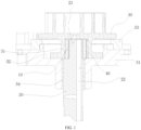
- the scroll compressor includes a rack 51, a cross slip ring 53, a crankshaft 20, a crankshaft bearing 54, an eccentric slider, an orbiting scroll 30, a static scroll (not illustrated), a housing (not illustrated), and so on.
- the static scroll is fixedly assembled on the housing and located at a top of the accommodation cavity.
- the rack 51 is mounted in the accommodation cavity.
- the orbiting scroll 30 is disposed at a side of the rack 51 facing towards the static scroll. A vortex sheet of the orbiting scroll 30 and a vortex sheet of the static scroll engage with each other to form a compression cavity.
- the orbiting scroll 30 is movable relative to the rack 51.
- the cross slip ring 53 is movably connected to the rack 51. A movement of the orbiting scroll 30 relative to the rack 51 is limited and guided by the cross slip ring 53.
- the crankshaft 20 is rotatably assembled to the rack 51 through the crankshaft bearing 54.
- An eccentric shaft segment 21 is disposed on the crankshaft 20.
- a side of the orbiting scroll 30 facing away from the static scroll has a mounting portion 31.
- the eccentric shaft segment 21 is in a drive connection to the mounting portion 31 through the eccentric slider.
- An oil storage cavity 52 is formed when the rack 51 is covered by the orbiting scroll 30.
- An oil passage 22 extending in an axial direction of the crankshaft 20 is formed in the crankshaft 20 and penetrates the eccentric shaft segment 21.
- the oil passage 22 is in communication with the oil storage cavity 52 and is extended to an oil pool at a bottom of the housing.
- oil is extracted from the oil pool through the oil passage 22 under the action of a centrifugal force generated by high-speed rotations of the crankshaft 20, flows down from a top end of the eccentric shaft segment 21, and enters between a circumferential surface of the eccentric slider and a corresponding side wall of the orbiting scroll.
- the oil may enter the oil storage cavity 52.
- the crankshaft bearing 54 and a position between an end surface of the mounting portion 31 of the orbiting scroll 30 and the rack 51 are lubricated with the oil in the oil storage cavity 52 to reduce wear and prolong a service life.
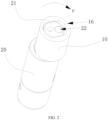
- the embodiments of the present disclosure provide an eccentric slider, as illustrated in FIG. 2 .
- the eccentric slider is assembled on the eccentric shaft segment 21 and mounted between the mounting portion 31 and the eccentric shaft segment 21. That is, the eccentric slider includes a slider body 10.
- An assembly hole 11 is formed in the slider body 10 and penetrates both ends of slider body 10 along an axis of the slider body 10.
- the eccentric shaft segment 21 is inserted in the assembly hole 11.
- an outer peripheral wall surface of the slider body 10 includes a bearing surface 12 and a non-bearing surface 13 opposite to the bearing surface 12.
- the bearing surface 12 is configured to drive the orbiting scroll 30.
- a hollow portion 14 is formed on the non-bearing surface 13.
- the hollow portion 14 corresponds to a space enclosed by a portion of the non-bearing surface 13 and a corresponding side wall of the orbiting scroll 30.
- the hollow portion 14 is configured to accommodate an oil compressed by the bearing surface 12 and the orbiting scroll 30 in a direction from the bearing surface 12 to the non-bearing surface 13.
- the eccentric slider provided by the embodiments of the present disclosure is assembled in the scroll compressor.
- the crankshaft 20 rotates, which enables the eccentric shaft segment 21 to drive the axis of the slider body 10 to rotate around an axis of the crankshaft 20 (in a direction r illustrated in FIG. 2 ), allowing the bearing surface 12 of the slider body 10 to compress a corresponding inner side wall of the orbiting scroll 30. Since the oil is stored between the bearing surface 12 and the corresponding inner side wall of the orbiting scroll 30, an oil film is formed by compressing the oil, and part of the compressed oil is forced to the hollow portion 14 of the non-bearing surface 13.
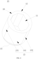
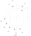
- the non-bearing surface 13 includes a hollow side surface 141.
- the hollow side surface 141 is formed as a side wall of the hollow portion 14.
- two sides of the hollow side surface 141 are respectively connected to two sides of the bearing surface 12.
- a distance from the hollow side surface 141 to a central axis of the slider body 10 is smaller than a distance from the bearing surface 12 to the central axis of the slider body 10. That is, the hollow side surface 141 is obtained by performing a machining process (through shaping of a turning machine or through grinding and shaping) on a circumferential surface of the cylindrical slider body 10.
- the non-bearing surface 13 further includes a first transition side surface 131 and a second transition side surface 132 that are respectively connected to the two sides of the hollow side surface 141.
- a side of the first transition side surface 131 facing away from the hollow side surface 141 is connected to one of the two sides of the bearing surface 12.
- a side of the second transition side surface 132 facing away from the hollow side surface 141 is connected to another side of the two sides of the bearing surface 12.
- the first transition side surface 131 and the second transition side surface 132 are formed as transitions between the bearing surface 12 and the hollow side surface 141, in such a manner that the bearing surface 12 is smoothly connected to the hollow side surface 141 to ensure a drive ability of the eccentric slider to the mounting portion 31.
- each of a distance from the first transition side surface 131 to the central axis of the slider body 10 and a distance from the second transition side surface 132 to the central axis of the slider body 10 is greater than the distance from the hollow side surface 141 to the central axis of the slider body 10 and smaller than or equal to the distance from the bearing surface to the central axis of the slider body 10. In some embodiments, each of the distance from the first transition side surface 131 to the central axis of the slider body 10 and the distance from the second transition side surface 132 to the central axis of the slider body 10 is smaller than the distance from the bearing surface to the central axis of the slider body 10.
- a stop edge 15 configured to avoid leakage of the oil is disposed on the hollow side surface 141 and fixedly connected to an end of the hollow side surface 141 facing away from the orbiting scroll 30.
- An arc side wall of the stop edge 15 is in substantial contact with the corresponding side wall of the orbiting scroll 30.
- the stop edge 15 can prevent the oil from leaking downwards at the hollow side surface 141 to enable the oil to stay at the hollow side surface 141 for a longer period of time. That is, the thickness of the oil film formed on the hollow side surface 141 is reduced, i.e., the shear force of the oil film is reduced.
- a thickness of the stop edge 15 in an axial direction of the slider body 10 is greater than or equal to 2 mm.
- the hollow portion 14 is a through groove 142 extending in the axial direction of the slider body 10. That is, both ends of the through groove 142 pass through two end surfaces of the slider body 10.
- the through groove 142 has an arc contour shape when the through groove 142 is cut along a direction perpendicular to the axis of the slider body 10.
- the through groove 142 may be machined and shaped by a milling machine.
- the stop edge 15 configured to avoid the leakage of the oil may be disposed at an end of the through groove 142 facing away from the orbiting scroll 30.
- the stop edge 15 can prevent the oil from leaking downwards at the through groove 142 to enable the oil to stay at the hollow side surface 141 for a longer period of time. That is, the thickness of the oil film formed on the hollow side surface 141 is reduced, i.e., the oil film shear force is reduced. In the embodiment, the thickness of the stop edge 15 in the axial direction of the slider body 10 is greater than or equal to 2 mm.
- the hollow portion 14 includes a plurality of through grooves 143 extending in an axis direction of the slider body 10.
- each through groove 143 is a straight groove parallel to the axis of the slider body 10.
- Two adjacent through grooves 143 of the plurality of through grooves 143 are spaced apart from each other.
- both ends of each through groove 143 pass through two end surfaces of the slider body 10.
- the plurality of through grooves 143 is arranged sequentially and forms a sawtooth contour.
- the stop edge 15 configured to avoid the leakage of the oil may be disposed at an end of the through groove 143 facing away from the orbiting scroll 30.
- the stop edge 15 can prevent the oil from leaking downwards at each through groove 143 to enable the oil to stay at the hollow side surface 141 for a longer period of time. That is, the thickness of the oil film formed on the hollow side surface 141 is reduced, i.e., the oil film shear force is reduced. In the embodiment, the thickness of the stop edge 15 in the axial direction of the slider body 10 is greater than or equal to 2 mm.
- a flow side surface 16 is disposed in a rear region of the bearing surface 12 and configured to allow for flowing of the oil in an extension direction of the central axis of the slider body 10.
- the oil flows out of a top of the eccentric shaft segment 21 and reaches an axial edge of the slider body 10
- the oil enters between the circumferential surface of the slider body 10 and the corresponding side wall of the orbiting scroll 30 (in this case, the oil flows to the hollow portion 14 and the flow side surface 16).
- the scroll compressor further includes an orbiting scroll bearing 40 fixedly mounted on the mounting portion 31.
- the slider body 10 is inserted in a bearing bore of the orbiting scroll bearing 40.
- An outer side wall of the slider body 10 is in a clearance fit with a bore wall of the bearing bore of the orbiting scroll bearing 40, in such a manner that the oil flowing out of the top of the eccentric shaft segment 21 can enter a gap between the circumferential surface of the slider body 10 and the bore wall of the bearing bore of the orbiting scroll bearing 40.
- the orbiting scroll bearing 40 is made of a material that is self-lubricated.
- a clearance between an outer peripheral wall of the slider body 10 and the bore wall of the bearing bore of the orbiting scroll bearing 40 ranges from 0.1 mm to 0.6 mm.
- a clearance H1 between the bearing surface 12 and the corresponding bore wall of the orbiting scroll bearing 40 ranges from 0.1 mm to 0.5 mm.
- a clearance H2 between a wall surface of the hollow portion 14 and a corresponding portion of the bore wall of the bearing bore ranges from 0.2 mm to 0.6 mm.
- the clearance H1 between the bearing surface 12 and the corresponding bore wall of the orbiting scroll bearing 40 is smaller than the clearance H2 between the wall surface of the hollow portion 14 and the corresponding portion of the bore wall of the bearing bore (i.e., H1 ⁇ H2).
- the oil is stored at the hollow portion 14, which effectively reduces a thickness of the oil film formed between the hollow portion 14 and the corresponding portion of the bore wall of the bearing bore. That is, the shear force of the oil film is reduced, which reduces the overall shear force of the oil film between the circumferential surface of the eccentric slider and the corresponding side wall of the orbiting scroll 30, effectively improving the performance and reliability of the scroll compressor.
- a temperature control device (not illustrated) is provided.
- the temperature control device includes the scroll compressor described earlier in the present disclosure.
- the scroll compressor is applied to compress a refrigerant of the temperature control device.
Landscapes
- Engineering & Computer Science (AREA)
- General Engineering & Computer Science (AREA)
- Mechanical Engineering (AREA)
- Ocean & Marine Engineering (AREA)
- Rotary Pumps (AREA)
Applications Claiming Priority (2)
| Application Number | Priority Date | Filing Date | Title |
|---|---|---|---|
| CN202210721766.3A CN114922817B (zh) | 2022-06-24 | 2022-06-24 | 曲轴用偏心滑块、涡旋压缩机及温控设备 |
| PCT/CN2023/093916 WO2023246366A1 (zh) | 2022-06-24 | 2023-05-12 | 曲轴用偏心滑块、涡旋压缩机及温控设备 |
Publications (2)
| Publication Number | Publication Date |
|---|---|
| EP4328451A1 true EP4328451A1 (de) | 2024-02-28 |
| EP4328451A4 EP4328451A4 (de) | 2024-08-28 |
Family
ID=82814550
Family Applications (1)
| Application Number | Title | Priority Date | Filing Date |
|---|---|---|---|
| EP23744353.6A Pending EP4328451A4 (de) | 2022-06-24 | 2023-05-12 | Exzentrischer gleitblock für kurbelwelle, spiralverdichter und temperatursteuerungsvorrichtung |
Country Status (5)
| Country | Link |
|---|---|
| US (1) | US12540642B2 (de) |
| EP (1) | EP4328451A4 (de) |
| JP (1) | JP7697751B2 (de) |
| CN (1) | CN114922817B (de) |
| WO (1) | WO2023246366A1 (de) |
Families Citing this family (3)
| Publication number | Priority date | Publication date | Assignee | Title |
|---|---|---|---|---|
| CN114922817B (zh) | 2022-06-24 | 2024-08-02 | 广东美的环境科技有限公司 | 曲轴用偏心滑块、涡旋压缩机及温控设备 |
| CN116292276B (zh) * | 2023-02-02 | 2025-04-25 | 广东美的环境科技有限公司 | 压缩机构、涡旋式压缩机和制冷设备 |
| CN119222161B (zh) * | 2023-06-28 | 2025-11-07 | 安徽威灵汽车部件有限公司 | 压缩机构的设计方法、压缩机构、压缩机和车辆 |
Family Cites Families (12)
| Publication number | Priority date | Publication date | Assignee | Title |
|---|---|---|---|---|
| US5011384A (en) * | 1989-12-01 | 1991-04-30 | Carrier Corporation | Slider block radial compliance mechanism for a scroll compressor |
| KR0130246Y1 (ko) * | 1996-07-23 | 1999-01-15 | 구자홍 | 스크롤 압축기용 슬라이드 부시의 실링구조 |
| JP3279236B2 (ja) * | 1997-11-26 | 2002-04-30 | ダイキン工業株式会社 | スクロール型流体機械 |
| US6354822B1 (en) * | 2000-05-16 | 2002-03-12 | Scroll Technologies | Oil retention in compressor slider block |
| JP2003286975A (ja) * | 2002-03-27 | 2003-10-10 | Mitsubishi Electric Corp | スクロール圧縮機 |
| CN103502645B (zh) * | 2011-04-22 | 2016-07-13 | 日立空调·家用电器株式会社 | 涡旋式压缩机 |
| CN104047851A (zh) * | 2014-07-11 | 2014-09-17 | 湖南联力精密机械有限公司 | 动盘和静盘可径向密封的涡旋空气压缩机 |
| WO2016170615A1 (ja) * | 2015-04-22 | 2016-10-27 | 三菱電機株式会社 | スクロール圧縮機 |
| CN209586676U (zh) * | 2019-03-05 | 2019-11-05 | 苏州为山之环境技术有限公司 | 一种具有双润滑通道传动组件的涡旋压缩机 |
| JP7263554B2 (ja) * | 2019-12-17 | 2023-04-24 | 日立ジョンソンコントロールズ空調株式会社 | スクロール圧縮機 |
| CN114439747B (zh) * | 2021-12-24 | 2023-11-10 | 珠海格力节能环保制冷技术研究中心有限公司 | 涡旋压缩机轴系润滑结构、涡旋压缩机、空调器 |
| CN114922817B (zh) * | 2022-06-24 | 2024-08-02 | 广东美的环境科技有限公司 | 曲轴用偏心滑块、涡旋压缩机及温控设备 |
-
2022
- 2022-06-24 CN CN202210721766.3A patent/CN114922817B/zh active Active
-
2023
- 2023-05-12 JP JP2023557419A patent/JP7697751B2/ja active Active
- 2023-05-12 EP EP23744353.6A patent/EP4328451A4/de active Pending
- 2023-05-12 WO PCT/CN2023/093916 patent/WO2023246366A1/zh not_active Ceased
- 2023-09-08 US US18/243,811 patent/US12540642B2/en active Active
Also Published As
| Publication number | Publication date |
|---|---|
| JP7697751B2 (ja) | 2025-06-24 |
| CN114922817A (zh) | 2022-08-19 |
| US12540642B2 (en) | 2026-02-03 |
| JP2024527215A (ja) | 2024-07-24 |
| US20230417272A1 (en) | 2023-12-28 |
| CN114922817B (zh) | 2024-08-02 |
| WO2023246366A1 (zh) | 2023-12-28 |
| EP4328451A4 (de) | 2024-08-28 |
Similar Documents
| Publication | Publication Date | Title |
|---|---|---|
| US12540642B2 (en) | Eccentric slider for crankshaft, scroll compressor, and temperature control device | |
| JPH01159480A (ja) | スクロール式機械 | |
| KR102619911B1 (ko) | 압축기 | |
| EP2700818A1 (de) | Spiralverdichter | |
| JP5963854B2 (ja) | 回転機械および冷凍サイクル機器 | |
| JPWO2019171427A1 (ja) | 圧縮機 | |
| JPWO2015025416A1 (ja) | 回転機械及び冷凍サイクル機器 | |
| JP6328322B2 (ja) | すべり軸受を有する圧縮機 | |
| CN221400932U (zh) | 曲轴、涡旋压缩机以及制冷设备 | |
| CN219754796U (zh) | 涡旋压缩机及车辆 | |
| CN220204129U (zh) | 一种压缩机的轴及压缩机 | |
| EP2228537A1 (de) | Einzelschraubenverdichter | |
| CN218598364U (zh) | 泵体组件、压缩机以及具有其的空调器 | |
| CN116292276B (zh) | 压缩机构、涡旋式压缩机和制冷设备 | |
| CN113446225A (zh) | 一种曲轴及涡旋式压缩机 | |
| JP2003286975A (ja) | スクロール圧縮機 | |
| US20210239113A1 (en) | Compressor Bearing | |
| CN111287963B (zh) | 旋转式压缩机、气体压缩系统、制冷系统和热泵系统 | |
| KR102696268B1 (ko) | 왕복동식 압축기 | |
| CN222315376U (zh) | 压缩机及制冷设备 | |
| CN216044298U (zh) | 一种泵体组件和压缩机 | |
| CN222334015U (zh) | 压缩机及制冷设备 | |
| CN114607610B (zh) | 泵体组件、压缩机以及具有的空调器 | |
| KR101454244B1 (ko) | 왕복동식 압축기 및 이를 적용한 냉동기기 | |
| KR0151285B1 (ko) | 로타리 압축기의 편심캠 |
Legal Events
| Date | Code | Title | Description |
|---|---|---|---|
| STAA | Information on the status of an ep patent application or granted ep patent |
Free format text: STATUS: UNKNOWN |
|
| STAA | Information on the status of an ep patent application or granted ep patent |
Free format text: STATUS: THE INTERNATIONAL PUBLICATION HAS BEEN MADE |
|
| PUAI | Public reference made under article 153(3) epc to a published international application that has entered the european phase |
Free format text: ORIGINAL CODE: 0009012 |
|
| STAA | Information on the status of an ep patent application or granted ep patent |
Free format text: STATUS: REQUEST FOR EXAMINATION WAS MADE |
|
| 17P | Request for examination filed |
Effective date: 20230801 |
|
| AK | Designated contracting states |
Kind code of ref document: A1 Designated state(s): AL AT BE BG CH CY CZ DE DK EE ES FI FR GB GR HR HU IE IS IT LI LT LU LV MC ME MK MT NL NO PL PT RO RS SE SI SK SM TR |
|
| A4 | Supplementary search report drawn up and despatched |
Effective date: 20240731 |
|
| RIC1 | Information provided on ipc code assigned before grant |
Ipc: F04C 29/02 20060101ALI20240725BHEP Ipc: F04C 18/02 20060101ALI20240725BHEP Ipc: F04C 29/00 20060101AFI20240725BHEP |
|
| STAA | Information on the status of an ep patent application or granted ep patent |
Free format text: STATUS: EXAMINATION IS IN PROGRESS |
|
| DAV | Request for validation of the european patent (deleted) | ||
| DAX | Request for extension of the european patent (deleted) | ||
| 17Q | First examination report despatched |
Effective date: 20250919 |