EP4327697B1 - Gleitschienenanordnung und gleitschienenkit - Google Patents
Gleitschienenanordnung und gleitschienenkit Download PDFInfo
- Publication number
- EP4327697B1 EP4327697B1 EP23153245.8A EP23153245A EP4327697B1 EP 4327697 B1 EP4327697 B1 EP 4327697B1 EP 23153245 A EP23153245 A EP 23153245A EP 4327697 B1 EP4327697 B1 EP 4327697B1
- Authority
- EP
- European Patent Office
- Prior art keywords
- rail
- blocking
- state
- working
- working member
- Prior art date
- Legal status (The legal status is an assumption and is not a legal conclusion. Google has not performed a legal analysis and makes no representation as to the accuracy of the status listed.)
- Active
Links
Images


Classifications
-
- A—HUMAN NECESSITIES
- A47—FURNITURE; DOMESTIC ARTICLES OR APPLIANCES; COFFEE MILLS; SPICE MILLS; SUCTION CLEANERS IN GENERAL
- A47B—TABLES; DESKS; OFFICE FURNITURE; CABINETS; DRAWERS; GENERAL DETAILS OF FURNITURE
- A47B88/00—Drawers for tables, cabinets or like furniture; Guides for drawers
- A47B88/50—Safety devices or the like for drawers
- A47B88/57—Safety devices or the like for drawers preventing complete withdrawal of the drawer
-
- A—HUMAN NECESSITIES
- A47—FURNITURE; DOMESTIC ARTICLES OR APPLIANCES; COFFEE MILLS; SPICE MILLS; SUCTION CLEANERS IN GENERAL
- A47B—TABLES; DESKS; OFFICE FURNITURE; CABINETS; DRAWERS; GENERAL DETAILS OF FURNITURE
- A47B88/00—Drawers for tables, cabinets or like furniture; Guides for drawers
- A47B88/40—Sliding drawers; Slides or guides therefor
- A47B88/473—Braking devices, e.g. linear or rotational dampers or friction brakes; Buffers; End stops
- A47B88/477—Buffers; End stops
-
- A—HUMAN NECESSITIES
- A47—FURNITURE; DOMESTIC ARTICLES OR APPLIANCES; COFFEE MILLS; SPICE MILLS; SUCTION CLEANERS IN GENERAL
- A47B—TABLES; DESKS; OFFICE FURNITURE; CABINETS; DRAWERS; GENERAL DETAILS OF FURNITURE
- A47B88/00—Drawers for tables, cabinets or like furniture; Guides for drawers
- A47B88/40—Sliding drawers; Slides or guides therefor
- A47B88/483—Sliding drawers; Slides or guides therefor with single extensible guides or parts
-
- A—HUMAN NECESSITIES
- A47—FURNITURE; DOMESTIC ARTICLES OR APPLIANCES; COFFEE MILLS; SPICE MILLS; SUCTION CLEANERS IN GENERAL
- A47B—TABLES; DESKS; OFFICE FURNITURE; CABINETS; DRAWERS; GENERAL DETAILS OF FURNITURE
- A47B2210/00—General construction of drawers, guides and guide devices
- A47B2210/0002—Guide construction for drawers
- A47B2210/0018—Buffers, stop blocks or latches for single drawer slides
Definitions
- the present invention relates to a slide rail assembly according to the pre-characterizing clause of claim 1.
- US Patent No. 6,935,710 B2 discloses a two-way retainer for a slide track assembly including a first slide track and a second slide track.
- the two-way retainer includes a retaining mechanism and a stop member respectively disposed on the first slide track and the second slide track.
- the retaining mechanism includes at least two retaining arms, and the stop member includes a blocking portion.
- the two retaining arms can be operated by at least one linkage to pivotally disengage from the blocking portion of the stop member to allow the first slide track to move with respect to the second slide track from the predetermined operating position toward a retracting direction for retracting the first slide track into the second slide track, or toward an opening direction for detaching the first slide track from the second slide track.
- an inner sliding rail mounting structure including a control plate pivotally connected to an inner sliding rail of a sliding track assembly and for engaging with a stop block of an intermediate sliding rail of the sliding track assembly to secure the inner sliding rail to the intermediate sliding rail, a slide pivotally connected to the control plate and coupled to the inner sliding rail by a slip joint, and a carriage affixed to the slide and configured to be operated to drive the slide to disengage the control plate from the stop block of the intermediate sliding rail for allowing removal of the inner sliding rail from the intermediately sliding rail.
- the present invention aims at providing a slide rail assembly.
- the claimed slide rail assembly includes a first rail, a second rail, a first working member, a first operating member and a blocking member.
- the first rail includes a blocking feature.
- the second rail is movable with respect to the first rail.
- the first working member is arranged on the second rail.
- the first operating member is configured to operate the first working member.
- the blocking member is arranged on the second rail.
- the blocking member When the blocking member is in a blocking state, the blocking member blocks the first operating member for restraining the first operating member from driving the first working member to disengage from the first state.
- the blocking member When the blocking member is in a non-blocking state, the blocking member does not block the first operating member for allowing the first operating member to drive the first working member from the first state to a second state, and when the first working member is in the second state, the first working member and the blocking feature do not block each other for allowing the second rail to move toward the first predetermined direction from the predetermined position.
- the claimed slide rail assembly further includes a second working member and a second operating member.
- the second working member is arranged on the second rail.
- the second operating member is configured to operate the second working member.
- the second rail When the second rail is located at the predetermined position with respect to the first rail and the second working member is in a third state, the second working member and the blocking feature block each other for restraining the second rail from moving toward a second predetermined direction
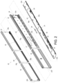
- a slide rail assembly 20 includes a first rail 22 and a second rail 24.
- the slide rail assembly 20 further includes a third rail 26.
- the first rail 22 is movably mounted between the third rail 26 and the second rail 24 and configured to extend a travelling distance of the second rail 24 with respect to the third rail 26.
- the third rail 26, the first rail 22 and the second rail 24 can respectively be an outer rail, a middle rail longitudinally movable with respect to the outer rail and an inner rail longitudinally movable with respect to the middle rail, i.e., the slide rail assembly 20 can be a three-segment type slide rail assembly.
- the slide rail assembly can include the first rail and the second rail only, and the first rail and the second rail can respectively be the outer rail and the inner rail longitudinally movable with respect to the outer rail, i.e., the slide rail assembly can be a two-segment type slide rail assembly.
- the third rail 26 includes a first wall 28a, a second wall 28b and a longitudinal wall 30 connected between the first wall 28a and the second wall 28b of the third rail 26.
- the first wall 28a, the second wall 28b and the third wall 30 of the third rail 26 cooperatively define a channel 32 of the third rail 26 for at least partially accommodating the first rail 22.
- the third rail 26 includes a front portion 26a and a rear portion 26.
- the first rail 22 includes a first wall 34a, a second wall 34b and a longitudinal wall 36 connected between the first wall 34a and the second wall 34b of the first rail 22.
- the first wall 34a, the second wall 34b and the longitudinal wall 36 of the first rail 22 cooperatively define a channel 38 of the first rail 22 for at least partially accommodating the second rail 24.
- the first rail 22 includes a front portion 22a and a rear portion 22b.
- the first rail 22 further includes a blocking feature 39 located inside the channel 38 of the first rail 22.
- the blocking feature 39 can be a protruding portion laterally or transversally protruding from the longitudinal wall 36 of the first rail 22 and located adjacent to the front portion 22a of the first rail 22.
- the present invention is not limited to this embodiment.
- the second rail 24 includes a first wall 40a, a second wall 40b and a longitudinal wall 42 connected between the first wall 40a and the second wall 40b of the second rail 24.
- the second rail 24 includes a front portion 24a and a rear portion 24b.
- At least one first slide facilitation device 35 is arranged inside the channel 32 of the third rail 26.
- the first slide facilitation device 35 includes a plurality of balls for facilitating the first rail 22 to slide with respect to the third rail 26 smoothly.
- at least one second slide facilitation device 37 is arranged inside the channel 38 of the first rail 22.
- the second slide facilitation device 37 includes a plurality of balls for facilitating the second rail 24 to slide with respect to the first rail 22 smoothly.
- present invention is not limited to this embodiment.
- the first slide facilitation device and/or the second slide facilitation device can be omitted.
- the slide rail assembly 20 further includes a first working member 44, which also can be named as a working member, a first operating member 46, which also can be named as an operating member, and a blocking member 48 arranged on the second rail 24, which also can be named as a slide rail.
- the second rail 24, the first working member 44 and the first operating member 46 and the blocking member 48 can cooperatively form a slide rail kit.
- the first operating member 46 is configured to operate the first working member 44.
- the blocking member 48 is configured to cooperate with the first operating member 46.
- the blocking member 48 is a resilient structure which is resiliently recoverable.
- the blocking member 48 can be a resilient plate.
- the present invention is not limited to this embodiment.
- the blocking member 48 includes a connecting segment 48a and a blocking segment 48b.
- the connecting segment 48a is connected, e.g., fixedly connected, to the second rail 24, and the blocking segment 48b extends from the connecting segment 48a.
- the blocking member 48 further includes an operating segment 48c connected to the blocking segment 48b.
- the operating segment 48c is configured to allow a user to operate the blocking segment 48b to resiliently move with respect to the connecting segment 48a easily.
- present invention is not limited to this embodiment.
- the operating segment can be omitted.
- the first rail can be omitted, and the second rail can be mounted on another component, e.g., a bracket or a frame, rather than the first rail.
- the first working member 44 is pivotally connected to the second rail 24 through a first pivoting shaft 50.
- the first operating member 46 is movably mounted on the second rail 24.
- the first operating member 46 can be moved with respect to the second rail 24 along a longitudinal direction of the second rail 24, and the second rail 24 can include at least one first retaining feature 33 configured to support the first operating member 46 for enhancing moving stability of the first operating member 46 when the first operating member 46 is operated to move.
- the present invention is not limited to this embodiment.
- the first operating member can be pivoted with respect to the second rail without any support provided by the first retaining feature.
- the first operating member 46 includes a first operating portion 51a, a first driving portion 51b and a first extending portion 51c connected between the first operating portion 51a and the first driving portion 51b.
- the slide rail assembly 20 further includes a resilient member 52 arranged on the second rail 24 and configured to resiliently force the first working member 44 for resiliently retaining the first working member 44 in a first state S1.
- the resilient member 52 can include a first resilient portion 54a configured to provide a first resilient force to the first working member 44.
- the present invention is not limited to this embodiment.
- the slide rail assembly 20 further includes a second working member 56 and a second operating member 58 arranged on the second rail 24 and configured to operate the second working member 56.
- the second operating member 58 includes a second operating portion 59a, a second driving portion 59b and a second extending portion 59c connected between the second operating portion 59a and the second driving portion 59b.
- the second working member 56 is pivotally connected to the second rail 24 through a second pivoting shaft 60.
- the second operating member 58 is movably mounted on the second rail 24.
- the second operating member 58 can be moved with respect to the second rail 24 along a longitudinal direction of the second rail 24, and the second rail 24 can include at least one second retaining feature 61 configured to support the second operating member 58 for enhancing moving stability of the second operating member 58 when the second operating member 58 is operated to move.
- the second operating member 58 also can be supported by at least one of the first wall 40a and the second wall 40b of the second rail 24, e.g., by the first wall 40a of the second rail 24.
- the present invention is not limited to this embodiment.
- the second operating member can be pivoted with respect to the second rail without any support provided by the second retaining feature or the wall of the second rail.
- the resilient member 52 is also configured to resiliently force the second working member 56 for resiliently retaining the second working member 56 in a third state S3.
- the resilient member 52 can further include a second resilient portion 54b configured to provide a second resilient force to the first working member 44.
- the present invention is not limited to this embodiment.
- the blocking member 48 When the blocking member 48 is in a blocking state K1, the blocking member 48 blocks the first operating member 46 for restraining the first operating member 46 from driving the first working member 44 to disengage from the first state as shown in FIG. 3 .
- the blocking member 48 is in a non-blocking state K2 as shown in FIG. 4 , e.g., when the blocking member 48 is driven by a first external force F1 provided by the user to switch from the blocking state K1 to the non-blocking state K2, the blocking member 48, e.g., the blocking segment 48b of the blocking member 48, is resiliently deformed to generate a recovering resilient force J opposite to the first external force F1, so that the blocking member 48 does not block the first operating member 46.
- the first operating member 46 is allowed to be driven by a second external force F2 as shown in FIG. 4 to move from a first position X1 as shown in FIG. 3 to a second position X2 as shown in FIG. 4 for driving the first working member 44 to switch from the first state S1 as shown in FIG. 3 to a second state S2 as shown in FIG. 4 .
- the blocking segment 48b of the blocking member 48 is located in a moving path of the first operating member 46 and blocks the first operating member 46 for restraining the first operating member 46 from driving the first working member 44 to disengage from the first state S1.
- the user can operate the blocking segment 48b of the blocking member 48, e.g., apply the first external force F1 onto the operating segment 48c of the blocking member 48 as shown in FIG. 4 , to drive the blocking segment 48b of the blocking member 48 to resiliently move with respect to the connecting segment 48a to switch the blocking member 48 from the blocking state K1 as shown in FIG.
- the blocking segment 48b of the blocking member 48 and the first operating member 46 are misaligned from each other, i.e., the blocking segment 48b of the blocking member 48 is not located in the moving path of the first operating member 46 and cannot block the first operating member 46, for allowing the first operating member 46 to be operated , e.g., by the second external force F2 applied onto the first operating portion 51a of the first operating member 46, to drive the first operating member 46 to move from the first position X1 as shown in FIG. 3 to the second position X2 as shown in FIG. 4 .
- the blocking member 48 is driven by the recovering resilient force J to recover to the blocking state as shown in FIG. 3 from the non-blocking state as shown in FIG. 4 , so that the blocking segment 48b of the blocking member 48 moves back in the moving path of the first operating member 46 and blocks the first operating member 46.
- the user has to switch the blocking member 48 to the non-blocking state, e.g., move the blocking segment 48b of the blocking member 48 out of the moving path of the first operating member 46 for not blocking the first operating member 46, so that the first operating member 46 is not restrained by the blocking member 48 and operable to drive the first working member 44.
- FIG. 5 When the slide rail assembly 20 is in a retracted state as shown in FIG. 5 , the first rail 22 and the second rail 24 are respectively retracted with respect to the third rail 26 and the first rail 22. At this moment, the second rail 24 can be located at a retracted position with respect to the first rail 22, and the first working member 44 and the second working member 56 can respectively be resiliently retained in the first state S1 and the third state S3 in response to the first resilient force and the second resilient force provided by the first resilient portion 54a and the second resilient portion 54b of the resilient member 52. Besides, the first operating member 46 can be located at the first position X1, and the blocking member 48 can be in the blocking state K1 which is the same as FIG. 3 .
- the first rail 22 is extended with respect to the third rail 26, i.e., the front portion 22 of the first rail 22 protrudes from the front portion 26a of the third rail 26, and the second rail 24 is movable with respect to the first rail 22 toward a first predetermined direction D1, which also can be named as a predetermined direction.
- the first predetermined direction D1 can be an opening direction.
- the present invention is not limited to this embodiment.
- the second rail 24 is located at a position as shown in FIG. 6 with respect to the first rail 22, the second working member 56 in the third state S3 is in contact with a first end portion 39a of the blocking feature 39 on the first rail 22.
- the blocking feature 39 can force the second working member 56 to drive the second working member 56 to pivot by a predetermined angle, e.g., to switch to a fourth state S4, for allowing the second working member 56 to pass over the first end portion 39a of the blocking member 39.
- the second resilient portion 54b of the resilient member 52 is resiliently deformed to generate the second resilient force.
- the second rail 24 further continues to move with respect to the first rail 22 toward the first predetermined direction D1 to a predetermined position P as shown in FIG. 8 , e.g., an extended position, it increases a protruding length of the front portion 24a of the second rail 24 from the front portion 22a of the first rail 22, so that the slide rail assembly 20 is in an extended state, e.g., fully extended state.
- the second working member 56 is not forced by the blocking feature 39 and is driven to switch back to the third state S3 in response to the second resilient force provided by the second resilient portion 54b of the resilient member 52.
- the second working member 56 in the third state and the first working member 44 in the first state S1 are located adjacent to the second end portion 39b and the first end portion 39a of the blocking feature 39.
- the first working member 44 and the second working member 56 can respectively block the first end portion 39a and the second end portion 39b of the blocking feature 39. Since the first working member 44 and the first end portion 39a of the blocking feature 39 block each other, the second rail 24 is restrained from moving from the predetermined position P toward the first predetermined direction. Furthermore, since the second working member 56 and the second end portion 39b of the blocking feature 39 block each other, the second rail 24 is restrained from moving from the predetermined position P toward a second predetermined direction D2.
- the second predetermined direction D2 can be a retracting direction opposite to the first predetermined direction D1.
- the present invention is not limited to this embodiment.
- FIG. 9 Please refer to FIG. 9 .
- the blocking segment 48b of the blocking member 48 and the first operating member 46 are misaligned from each other, so that the blocking member 48 does not block the first operating member 46 to allow the first operating member 46 to be driven by the second external force F2 to move from the first position X1 as shown in FIG. 8 to the second position X2 as shown in FIG. 9 for driving the first working member 44 to switch from the first state S1 as shown in FIG. 8 to the second state S2 as shown in FIG. 9 .
- the first working member 44 and the first end portion 39a of the blocking feature 39 do not block each other, so that the second rail 24 is allowed to be detached from the channel 38 of the first rail 22 by moving the second rail 24 toward the first predetermined direction D1 from the predetermined position P.
- FIG. 10 Please refer to FIG. 10 .
- the first operating member 46 can be moved back to the first position X1, so that the blocking member 48 can recover to the non-blocking state from the blocking state to move the blocking segment 48b of the blocking member 48 in the moving path of the first operating member 46 for blocking the first operating member 46.
- the first working member 44 is driven by the first resilient force provided by the first resilient portion 54a of the resilient member 52 to switch from the second state S2 to the first state S1.
- FIG. 8 and FIG. 11 Please refer to FIG. 8 and FIG. 11 .
- the second operating member 58 is operable to drive the second working member 56 to switch from the third state S3 as shown in FIG. 8 to the fourth state S4 as shown in FIG. 11 , so that the second working member 56 and the second end portion 39b of the blocking feature 39 do not block each other for allowing the second rail 24 to move toward the second predetermined direction D2 from the predetermined position P.
- the user can operate the second operating member 58, e.g., apply a third external force F3 onto the second operating portion 59a of the second operating member 58, to move the second operating member 58 with respect to the second rail 24 for driving the second working member 56 to switch from the third state S3 as shown in FIG. 8 to the fourth state S4 as shown in FIG. 11 .
- the second working member 56 is in the fourth state S4
- the second working member 56 and the second end portion 39b of the blocking feature 39 do not block each other for allowing the second rail 24 to move toward the second predetermined direction D2 from the predetermined position P.
- the second working member and the second operating member can be omitted, so that the slide rail assembly can only selectively restrain or allow the second rail to move toward the first predetermined direction from the predetermined position by cooperation of the first working member and the second operating member.
- a blocking member 200 can be loaded by an auxiliary resilient member 202, such as a spring, so that the blocking member 200 is recoverable by the auxiliary resilient member 202.
- the blocking member 200 blocks the first operating member 46 for restraining the first operating member 46 from driving the first working member 44 to disengage from the first state S1.
- the second rail 24 includes a predetermined wall 204.
- the predetermined wall 204 can be a protruding object.
- the predetermined wall 204 can facilitate the blocking member 200 to block the first operating member 46 and enhance blocking strength of the blocking member 200 against the first operating member 46.
- the blocking member 200 When the blocking member 200 is forced by a first external force F1' provided by the user to switch to a non-blocking state K2' as shown in FIG. 13 , the blocking member 200 and the first operating member 46 are misaligned from each other, so that the blocking member 200 does not block the first operating member 46 for allowing the first operating member 46 to disengage from the first position X1, e.g., move from the first position X1 to the second position X2, so as to drive the first working member 44 to switch from the first state S1 to the second state S2.
- the auxiliary resilient member 202 is resiliently deformed to generate a recovering resilient force J'.
- the blocking member 200 can be driven by the recovering resilient force J' provided by the auxiliary resilient member 202 to switch from the non-blocking state K2' as shown in FIG. 13 to the blocking state K1' as shown in FIG. 12 to block the first operating member 46.
- the present invention includes the following feature:
Landscapes
- Drawers Of Furniture (AREA)
- Machines For Laying And Maintaining Railways (AREA)
- Holders For Apparel And Elements Relating To Apparel (AREA)
Claims (10)
- Gleitschienenanordnung (20), welche umfasst:eine erste Schiene (22) mit einem Blockiermerkmal (39);eine zweite Schiene (24), die in Bezug auf die erste Schiene (22) beweglich ist;ein erstes Arbeitselement (44), das an der zweiten Schiene (24) angeordnet ist;ein erstes Betätigungselement (46), das ausgestaltet ist, das erste Arbeitselement (44) zu betätigen; undein Blockierelement (48, 200), das an der zweiten Schiene (24) angeordnet ist;wobei, wenn sich die zweite Schiene (24) in einer bestimmten Position (P) in Bezug auf die erste Schiene (22) befindet und das erste Arbeitselement (44) in einem ersten Zustand (S1) ist, das erste Arbeitselement (44) und das Blockiermerkmal (39) einander blockieren, um die zweite Schiene (24) daran zu hindern, sich aus der bestimmten Position (P) in eine erste bestimmte Richtung (D1) zu bewegen;wobei, wenn das Blockierelement (48, 200) in einem Blockierzustand (K1, K1') ist, das Blockierelement (48, 200) das erste Betätigungselement (46) blockiert, um das erste Betätigungselement (46) daran zu hindern, das erste Arbeitselement (44) anzutreiben, sich aus dem ersten Zustand (S1) zu lösen;wobei, wenn sich das Blockierelement (48, 200) in einem Nicht-Blockierzustand (K2, K2') befindet, das Blockierelement (48, 200) das erste Betätigungselement (46) nicht blockiert, damit das erste Betätigungselement (46) das erste Arbeitselement (44) aus dem ersten Zustand (S1) in einen zweiten Zustand (S2) antreiben kann, und wenn sich das erste Arbeitselement (44) in dem zweiten Zustand (S2) befindet, das erste Arbeitselement (44) und das Blockiermerkmal (39) einander nicht blockieren, damit sich die zweite Schiene (24) von der bestimmten Position (P) in die erste bestimmte Richtung (D1) bewegen kann;ferner gekennzeichnet durch ein zweites Arbeitselement (56) und ein zweites Betätigungselement (58), wobei das zweite Arbeitselement (56) an der zweiten Schiene (24) angeordnet ist, wobei das zweite Betätigungselement (58) ausgestaltet ist, das zweite Arbeitselement (56) zu betätigen, wenn sich die zweite Schiene (24) in der bestimmten Position (P) in Bezug auf die erste Schiene (22) befindet und das zweite Arbeitselement (56) sich in einem dritten Zustand (S3) befindet, das zweite Arbeitselement (56) und das Blockiermerkmal (39) einander blockieren, um die zweite Schiene (24) daran zu hindern, sich aus der bestimmten Position (P) in eine zweite bestimmte Richtung (D2) zu bewegen.
- Gleitschienenanordnung (20) nach Anspruch 1, dadurch gekennzeichnet, dass das Blockierelement (48, 200) an der zweiten Schiene (24) angeordnet und elastisch rückstellbar ist, wobei, wenn das Blockierelement (48, 200) gezwungen wird, vom Blockierzustand (K1, K1') in einen Nicht-Blockierzustand (K2, K2') zu wechseln, das Blockierelement (48, 200) das erste Betätigungselement (46) nicht blockiert, um es dem ersten Betätigungselement (46) zu ermöglichen, das erste Arbeitselement (44) von dem ersten Zustand (S1) in einen zweiten Zustand (S2) zu treiben, und wenn das Blockierelement (48, 200) in dem Nicht-Blockierzustand (K2, K2') freigegeben wird, sich das Blockierelement (48, 200) elastisch zurückstellt, um von dem Nicht-Blockierzustand (K2, K2') in den Blockierzustand (K1, K1') zu wechseln.
- Gleitschienenanordnung (20) nach einem der Ansprüche 1 und 2, dadurch gekennzeichnet, dass die erste bestimmte Richtung (D1) eine Öffnungsrichtung ist.
- Gleitschienenanordnung (20) nach einem der Ansprüche 1 bis 3, dadurch gekennzeichnet, dass die erste Schiene (22) eine erste Wand (34a), eine zweite Wand (34b) und eine Längswand (36) aufweist, worin die Längswand (36) der ersten Schiene (22) zwischen der ersten Wand (34a) und der zweiten Wand (34b) der ersten Schiene (22) verbunden ist, die erste Wand (34a), die zweite Wand (34b) und die Längswand (36) der ersten Schiene (22) zusammen einen Kanal (38) zur Aufnahme der zweiten Schiene (24) definieren, wobei, wenn sich das Blockierelement (48, 200) in dem Nicht-Blockierzustand (K2, K2') befindet, das Blockierelement (48, 200) das erste Betätigungselement (46) nicht blockiert, damit das erste Betätigungselement (46) das erste Arbeitselement (44) aus dem ersten Zustand (S1) in den zweiten Zustand (S2) antreiben kann, und wenn sich das erste Arbeitselement (44) im zweiten Zustand (S2) befindet, das erste Arbeitselement (44) und das Blockiermerkmal (39) einander nicht blockieren, damit die zweite Schiene (24) aus dem Kanal (38) gelöst werden kann, indem die zweite Schiene (24) aus der bestimmten Position (P) in die erste bestimmte Richtung (D1) bewegt wird.
- Gleitschienenanordnung (20) nach einem der Ansprüche 1 bis 4, dadurch gekennzeichnet, dass das erste Betätigungselement (46) beweglich an der zweiten Schiene (24) angebracht ist.
- Gleitschienenanordnung (20) nach einem der Ansprüche 1 bis 5, dadurch gekennzeichnet, dass das erste Arbeitselement (44) schwenkbar mit der zweiten Schiene (24) verbunden ist.
- Gleitschienenanordnung (20) nach einem der Ansprüche 1 bis 6, ferner gekennzeichnet durch ein elastisches Element (52), das ausgestaltet ist, eine elastische Kraft auf das erste Arbeitselement (44) auszuüben, um das erste Arbeitselement (44) elastisch in dem ersten Zustand (S1) zu halten.
- Gleitschienenanordnung (20) nach einem der Ansprüche 1 bis 7, dadurch gekennzeichnet, dass die erste Schiene (22) einen vorderen Abschnitt (22a) und einen hinteren Abschnitt (22b) umfasst, und dass das Blockiermerkmal (39) dem vorderen Abschnitt (22a) der ersten Schiene (22) benachbart angeordnet ist.
- Gleitschienenanordnung (20) nach einem der Ansprüche 1 bis 8, dadurch gekennzeichnet, dass, wenn das zweite Betätigungselement (58) das zweite Arbeitselement (56) aus dem dritten Zustand (S3) in einen vierten Zustand (S4) antreibt, das zweite Arbeitselement (56) und das Blockiermerkmal (39) sich nicht gegenseitig blockieren, um zu ermöglichen, dass sich die zweite Schiene (24) aus der bestimmten Position (P) in die zweite bestimmte Richtung (D2) bewegt.
- Gleitschienenanordnung (20) nach einem der Ansprüche 1 bis 9, dadurch gekennzeichnet, dass die zweite bestimmte Richtung (D2) eine Rückzugsrichtung ist.
Applications Claiming Priority (1)
| Application Number | Priority Date | Filing Date | Title |
|---|---|---|---|
| TW111132228A TWI818694B (zh) | 2022-08-24 | 2022-08-24 | 滑軌總成及其滑軌套件 |
Publications (2)
| Publication Number | Publication Date |
|---|---|
| EP4327697A1 EP4327697A1 (de) | 2024-02-28 |
| EP4327697B1 true EP4327697B1 (de) | 2025-06-18 |
Family
ID=85076132
Family Applications (1)
| Application Number | Title | Priority Date | Filing Date |
|---|---|---|---|
| EP23153245.8A Active EP4327697B1 (de) | 2022-08-24 | 2023-01-25 | Gleitschienenanordnung und gleitschienenkit |
Country Status (4)
| Country | Link |
|---|---|
| US (1) | US12127673B2 (de) |
| EP (1) | EP4327697B1 (de) |
| JP (1) | JP7458522B2 (de) |
| TW (1) | TWI818694B (de) |
Families Citing this family (1)
| Publication number | Priority date | Publication date | Assignee | Title |
|---|---|---|---|---|
| TWI856894B (zh) * | 2023-12-01 | 2024-09-21 | 川湖科技股份有限公司 | 滑軌總成 |
Family Cites Families (19)
| Publication number | Priority date | Publication date | Assignee | Title |
|---|---|---|---|---|
| US5248195A (en) * | 1992-08-06 | 1993-09-28 | Chern Jia Enterprise Co., Ltd. | Separable bottom mounted drawer slide assembly |
| TW584761B (en) * | 2000-01-12 | 2004-04-21 | Howa Bussan Kk | Plane lighting device |
| US6935710B2 (en) * | 2003-03-05 | 2005-08-30 | King Slide Works Co., Ltd. | Two-way retainer for a slide track assembly of drawers |
| US6945619B1 (en) * | 2004-08-13 | 2005-09-20 | King Slide Works Co., Ltd. | Positioning device for a slide |
| TWM292954U (en) | 2005-11-16 | 2006-07-01 | Gslide Corp | Improved internal slide rail detaching structure of drawer slide rail |
| GB2453736B (en) * | 2007-10-16 | 2009-09-02 | King Slide Works Co Ltd | A slide rail assembly |
| TWI584761B (zh) | 2016-09-13 | 2017-06-01 | 川湖科技股份有限公司 | 滑軌總成 |
| US10111357B2 (en) | 2017-03-20 | 2018-10-23 | Gslide Corporation | Detachable inner sliding rail mounting structure for server sliding rail assembly |
| TWI665983B (zh) * | 2017-04-12 | 2019-07-21 | 川湖科技股份有限公司 | 滑軌總成 |
| TWI646923B (zh) * | 2017-11-27 | 2019-01-11 | 川湖科技股份有限公司 | 滑軌總成及其滑軌套件 |
| TWI658803B (zh) * | 2017-12-28 | 2019-05-11 | 川湖科技股份有限公司 | 滑軌總成及其滑軌套件 |
| TWI687178B (zh) * | 2018-05-07 | 2020-03-11 | 川湖科技股份有限公司 | 滑軌總成及其滑軌套件 |
| TWI683638B (zh) * | 2019-01-08 | 2020-02-01 | 川湖科技股份有限公司 | 滑軌總成及其滑軌套件 |
| TWI721493B (zh) * | 2019-07-12 | 2021-03-11 | 川湖科技股份有限公司 | 滑軌總成 |
| CN112237345B (zh) * | 2019-07-19 | 2022-04-26 | 川湖科技股份有限公司 | 滑轨总成 |
| TWI704890B (zh) * | 2019-10-18 | 2020-09-21 | 川湖科技股份有限公司 | 滑軌總成及其滑軌套件 |
| TWI706748B (zh) * | 2019-12-16 | 2020-10-11 | 川湖科技股份有限公司 | 滑軌總成 |
| TWI717311B (zh) * | 2020-08-28 | 2021-01-21 | 川湖科技股份有限公司 | 滑軌總成 |
| TWI742835B (zh) * | 2020-09-01 | 2021-10-11 | 川湖科技股份有限公司 | 滑軌總成及其滑軌套件 |
-
2022
- 2022-08-24 TW TW111132228A patent/TWI818694B/zh active
- 2022-12-19 US US18/083,590 patent/US12127673B2/en active Active
-
2023
- 2023-01-25 EP EP23153245.8A patent/EP4327697B1/de active Active
- 2023-02-08 JP JP2023017486A patent/JP7458522B2/ja active Active
Also Published As
| Publication number | Publication date |
|---|---|
| JP2024031748A (ja) | 2024-03-07 |
| US20240065438A1 (en) | 2024-02-29 |
| TWI818694B (zh) | 2023-10-11 |
| EP4327697A1 (de) | 2024-02-28 |
| TW202408404A (zh) | 2024-03-01 |
| US12127673B2 (en) | 2024-10-29 |
| JP7458522B2 (ja) | 2024-03-29 |
Similar Documents
| Publication | Publication Date | Title |
|---|---|---|
| US10806255B1 (en) | Slide rail assembly | |
| EP3750445B1 (de) | Gleitschienenanordnung und betriebsverfahren dafür | |
| JP6715797B2 (ja) | スライドレールアセンブリ | |
| TWI704889B (zh) | 滑軌總成 | |
| EP4327697B1 (de) | Gleitschienenanordnung und gleitschienenkit | |
| KR101972158B1 (ko) | 차량용 드라이브 메커니즘 및 차량용 패널들의 이동 방법 | |
| EP3821762B1 (de) | Gleitschienenanordnung | |
| TWI706749B (zh) | 滑軌總成 | |
| EP4501174B1 (de) | Gleitschienenanordnung | |
| EP3730002A1 (de) | Rückprallvorrichtung für gleitschienen | |
| JPH0740746A (ja) | 車両用サンルーフ装置のチエツク機構 | |
| EP4327696B1 (de) | Schienenanordnung | |
| CN212022281U (zh) | 天窗装置 | |
| EP3387951B1 (de) | Kupplungssystem für möbelteile | |
| CN212579582U (zh) | 天窗装置 | |
| EP4521864A1 (de) | Antriebsmechanismus | |
| JP2009018390A (ja) | ロボットハンド | |
| EP4648558A1 (de) | Gestellmontagekit | |
| EP4454514B1 (de) | Gleitschienenanordnung | |
| EP4456686A1 (de) | Gleitschienenanordnung | |
| CN114766847B (zh) | 滑轨总成 | |
| US11877419B2 (en) | Chassis structure and electronic device therewith | |
| CN112901656B (zh) | 滑轨总成 | |
| CN212332598U (zh) | 雨刷的翘板式组装装置 | |
| CN209585908U (zh) | 一种具有冗余驱动功能的智能防盗门锁 |
Legal Events
| Date | Code | Title | Description |
|---|---|---|---|
| PUAI | Public reference made under article 153(3) epc to a published international application that has entered the european phase |
Free format text: ORIGINAL CODE: 0009012 |
|
| STAA | Information on the status of an ep patent application or granted ep patent |
Free format text: STATUS: THE APPLICATION HAS BEEN PUBLISHED |
|
| AK | Designated contracting states |
Kind code of ref document: A1 Designated state(s): AL AT BE BG CH CY CZ DE DK EE ES FI FR GB GR HR HU IE IS IT LI LT LU LV MC ME MK MT NL NO PL PT RO RS SE SI SK SM TR |
|
| STAA | Information on the status of an ep patent application or granted ep patent |
Free format text: STATUS: REQUEST FOR EXAMINATION WAS MADE |
|
| 17P | Request for examination filed |
Effective date: 20240617 |
|
| RBV | Designated contracting states (corrected) |
Designated state(s): AL AT BE BG CH CY CZ DE DK EE ES FI FR GB GR HR HU IE IS IT LI LT LU LV MC ME MK MT NL NO PL PT RO RS SE SI SK SM TR |
|
| GRAP | Despatch of communication of intention to grant a patent |
Free format text: ORIGINAL CODE: EPIDOSNIGR1 |
|
| STAA | Information on the status of an ep patent application or granted ep patent |
Free format text: STATUS: GRANT OF PATENT IS INTENDED |
|
| RIC1 | Information provided on ipc code assigned before grant |
Ipc: A47B 88/57 20170101AFI20250213BHEP |
|
| INTG | Intention to grant announced |
Effective date: 20250221 |
|
| GRAS | Grant fee paid |
Free format text: ORIGINAL CODE: EPIDOSNIGR3 |
|
| GRAA | (expected) grant |
Free format text: ORIGINAL CODE: 0009210 |
|
| STAA | Information on the status of an ep patent application or granted ep patent |
Free format text: STATUS: THE PATENT HAS BEEN GRANTED |
|
| AK | Designated contracting states |
Kind code of ref document: B1 Designated state(s): AL AT BE BG CH CY CZ DE DK EE ES FI FR GB GR HR HU IE IS IT LI LT LU LV MC ME MK MT NL NO PL PT RO RS SE SI SK SM TR |
|
| REG | Reference to a national code |
Ref country code: GB Ref legal event code: FG4D |
|
| REG | Reference to a national code |
Ref country code: CH Ref legal event code: EP |
|
| REG | Reference to a national code |
Ref country code: DE Ref legal event code: R096 Ref document number: 602023004005 Country of ref document: DE |
|
| REG | Reference to a national code |
Ref country code: CH Ref legal event code: EP |
|
| REG | Reference to a national code |
Ref country code: IE Ref legal event code: FG4D |
|
| PG25 | Lapsed in a contracting state [announced via postgrant information from national office to epo] |
Ref country code: FI Free format text: LAPSE BECAUSE OF FAILURE TO SUBMIT A TRANSLATION OF THE DESCRIPTION OR TO PAY THE FEE WITHIN THE PRESCRIBED TIME-LIMIT Effective date: 20250618 |
|
| REG | Reference to a national code |
Ref country code: LT Ref legal event code: MG9D |
|
| PG25 | Lapsed in a contracting state [announced via postgrant information from national office to epo] |
Ref country code: GR Free format text: LAPSE BECAUSE OF FAILURE TO SUBMIT A TRANSLATION OF THE DESCRIPTION OR TO PAY THE FEE WITHIN THE PRESCRIBED TIME-LIMIT Effective date: 20250919 Ref country code: NO Free format text: LAPSE BECAUSE OF FAILURE TO SUBMIT A TRANSLATION OF THE DESCRIPTION OR TO PAY THE FEE WITHIN THE PRESCRIBED TIME-LIMIT Effective date: 20250918 |
|
| PG25 | Lapsed in a contracting state [announced via postgrant information from national office to epo] |
Ref country code: BG Free format text: LAPSE BECAUSE OF FAILURE TO SUBMIT A TRANSLATION OF THE DESCRIPTION OR TO PAY THE FEE WITHIN THE PRESCRIBED TIME-LIMIT Effective date: 20250618 |
|
| PG25 | Lapsed in a contracting state [announced via postgrant information from national office to epo] |
Ref country code: HR Free format text: LAPSE BECAUSE OF FAILURE TO SUBMIT A TRANSLATION OF THE DESCRIPTION OR TO PAY THE FEE WITHIN THE PRESCRIBED TIME-LIMIT Effective date: 20250618 |
|
| PG25 | Lapsed in a contracting state [announced via postgrant information from national office to epo] |
Ref country code: RS Free format text: LAPSE BECAUSE OF FAILURE TO SUBMIT A TRANSLATION OF THE DESCRIPTION OR TO PAY THE FEE WITHIN THE PRESCRIBED TIME-LIMIT Effective date: 20250918 |
|
| REG | Reference to a national code |
Ref country code: NL Ref legal event code: MP Effective date: 20250618 |
|
| PG25 | Lapsed in a contracting state [announced via postgrant information from national office to epo] |
Ref country code: LV Free format text: LAPSE BECAUSE OF FAILURE TO SUBMIT A TRANSLATION OF THE DESCRIPTION OR TO PAY THE FEE WITHIN THE PRESCRIBED TIME-LIMIT Effective date: 20250618 |
|
| PG25 | Lapsed in a contracting state [announced via postgrant information from national office to epo] |
Ref country code: NL Free format text: LAPSE BECAUSE OF FAILURE TO SUBMIT A TRANSLATION OF THE DESCRIPTION OR TO PAY THE FEE WITHIN THE PRESCRIBED TIME-LIMIT Effective date: 20250618 |
|
| PG25 | Lapsed in a contracting state [announced via postgrant information from national office to epo] |
Ref country code: PT Free format text: LAPSE BECAUSE OF FAILURE TO SUBMIT A TRANSLATION OF THE DESCRIPTION OR TO PAY THE FEE WITHIN THE PRESCRIBED TIME-LIMIT Effective date: 20251020 |
|
| REG | Reference to a national code |
Ref country code: AT Ref legal event code: MK05 Ref document number: 1803400 Country of ref document: AT Kind code of ref document: T Effective date: 20250618 |
|
| PG25 | Lapsed in a contracting state [announced via postgrant information from national office to epo] |
Ref country code: IS Free format text: LAPSE BECAUSE OF FAILURE TO SUBMIT A TRANSLATION OF THE DESCRIPTION OR TO PAY THE FEE WITHIN THE PRESCRIBED TIME-LIMIT Effective date: 20251018 |
|
| PG25 | Lapsed in a contracting state [announced via postgrant information from national office to epo] |
Ref country code: AT Free format text: LAPSE BECAUSE OF FAILURE TO SUBMIT A TRANSLATION OF THE DESCRIPTION OR TO PAY THE FEE WITHIN THE PRESCRIBED TIME-LIMIT Effective date: 20250618 Ref country code: SM Free format text: LAPSE BECAUSE OF FAILURE TO SUBMIT A TRANSLATION OF THE DESCRIPTION OR TO PAY THE FEE WITHIN THE PRESCRIBED TIME-LIMIT Effective date: 20250618 |
|
| PG25 | Lapsed in a contracting state [announced via postgrant information from national office to epo] |
Ref country code: CZ Free format text: LAPSE BECAUSE OF FAILURE TO SUBMIT A TRANSLATION OF THE DESCRIPTION OR TO PAY THE FEE WITHIN THE PRESCRIBED TIME-LIMIT Effective date: 20250618 |
|
| PG25 | Lapsed in a contracting state [announced via postgrant information from national office to epo] |
Ref country code: PL Free format text: LAPSE BECAUSE OF FAILURE TO SUBMIT A TRANSLATION OF THE DESCRIPTION OR TO PAY THE FEE WITHIN THE PRESCRIBED TIME-LIMIT Effective date: 20250618 |
|
| PG25 | Lapsed in a contracting state [announced via postgrant information from national office to epo] |
Ref country code: EE Free format text: LAPSE BECAUSE OF FAILURE TO SUBMIT A TRANSLATION OF THE DESCRIPTION OR TO PAY THE FEE WITHIN THE PRESCRIBED TIME-LIMIT Effective date: 20250618 |
|
| PG25 | Lapsed in a contracting state [announced via postgrant information from national office to epo] |
Ref country code: SK Free format text: LAPSE BECAUSE OF FAILURE TO SUBMIT A TRANSLATION OF THE DESCRIPTION OR TO PAY THE FEE WITHIN THE PRESCRIBED TIME-LIMIT Effective date: 20250618 |
|
| PG25 | Lapsed in a contracting state [announced via postgrant information from national office to epo] |
Ref country code: ES Free format text: LAPSE BECAUSE OF FAILURE TO SUBMIT A TRANSLATION OF THE DESCRIPTION OR TO PAY THE FEE WITHIN THE PRESCRIBED TIME-LIMIT Effective date: 20250618 |