EP4324356A1 - Vorrichtung zum halten und/oder transportieren, verwendung und verfahren - Google Patents
Vorrichtung zum halten und/oder transportieren, verwendung und verfahren Download PDFInfo
- Publication number
- EP4324356A1 EP4324356A1 EP23000114.1A EP23000114A EP4324356A1 EP 4324356 A1 EP4324356 A1 EP 4324356A1 EP 23000114 A EP23000114 A EP 23000114A EP 4324356 A1 EP4324356 A1 EP 4324356A1
- Authority
- EP
- European Patent Office
- Prior art keywords
- holding device
- holding
- notebook
- magnetic
- laptop
- Prior art date
- Legal status (The legal status is an assumption and is not a legal conclusion. Google has not performed a legal analysis and makes no representation as to the accuracy of the status listed.)
- Granted
Links
Images


Classifications
-
- A—HUMAN NECESSITIES
- A45—HAND OR TRAVELLING ARTICLES
- A45C—PURSES; LUGGAGE; HAND CARRIED BAGS
- A45C13/00—Details; Accessories
- A45C13/10—Arrangement of fasteners
- A45C13/1069—Arrangement of fasteners magnetic
-
- A—HUMAN NECESSITIES
- A45—HAND OR TRAVELLING ARTICLES
- A45C—PURSES; LUGGAGE; HAND CARRIED BAGS
- A45C11/00—Receptacles for purposes not provided for in groups A45C1/00-A45C9/00
- A45C11/003—Receptacles for purposes not provided for in groups A45C1/00-A45C9/00 for storing portable computing devices, e.g. laptops, tablets or calculators
-
- A—HUMAN NECESSITIES
- A45—HAND OR TRAVELLING ARTICLES
- A45F—TRAVELLING OR CAMP EQUIPMENT: SACKS OR PACKS CARRIED ON THE BODY
- A45F5/00—Holders or carriers for hand articles; Holders or carriers for use while travelling or camping
- A45F5/1525—Holders or carriers for portable computing devices, e.g. laptops, tablets or calculators
-
- F—MECHANICAL ENGINEERING; LIGHTING; HEATING; WEAPONS; BLASTING
- F16—ENGINEERING ELEMENTS AND UNITS; GENERAL MEASURES FOR PRODUCING AND MAINTAINING EFFECTIVE FUNCTIONING OF MACHINES OR INSTALLATIONS; THERMAL INSULATION IN GENERAL
- F16M—FRAMES, CASINGS OR BEDS OF ENGINES, MACHINES OR APPARATUS, NOT SPECIFIC TO ENGINES, MACHINES OR APPARATUS PROVIDED FOR ELSEWHERE; STANDS; SUPPORTS
- F16M11/00—Stands or trestles as supports for apparatus or articles placed thereon ; Stands for scientific apparatus such as gravitational force meters
- F16M11/02—Heads
- F16M11/04—Means for attachment of apparatus; Means allowing adjustment of the apparatus relatively to the stand
- F16M11/06—Means for attachment of apparatus; Means allowing adjustment of the apparatus relatively to the stand allowing pivoting
- F16M11/10—Means for attachment of apparatus; Means allowing adjustment of the apparatus relatively to the stand allowing pivoting around a horizontal axis
-
- F—MECHANICAL ENGINEERING; LIGHTING; HEATING; WEAPONS; BLASTING
- F16—ENGINEERING ELEMENTS AND UNITS; GENERAL MEASURES FOR PRODUCING AND MAINTAINING EFFECTIVE FUNCTIONING OF MACHINES OR INSTALLATIONS; THERMAL INSULATION IN GENERAL
- F16M—FRAMES, CASINGS OR BEDS OF ENGINES, MACHINES OR APPARATUS, NOT SPECIFIC TO ENGINES, MACHINES OR APPARATUS PROVIDED FOR ELSEWHERE; STANDS; SUPPORTS
- F16M13/00—Other supports for positioning apparatus or articles; Means for steadying hand-held apparatus or articles
- F16M13/02—Other supports for positioning apparatus or articles; Means for steadying hand-held apparatus or articles for supporting on, or attaching to, an object, e.g. tree, gate, window-frame, cycle
-
- G—PHYSICS
- G06—COMPUTING OR CALCULATING; COUNTING
- G06F—ELECTRIC DIGITAL DATA PROCESSING
- G06F1/00—Details not covered by groups G06F3/00 - G06F13/00 and G06F21/00
- G06F1/16—Constructional details or arrangements
- G06F1/1613—Constructional details or arrangements for portable computers
- G06F1/1628—Enclosures for carrying portable computers with peripheral devices, e.g. cases for a laptop and a printer
-
- A—HUMAN NECESSITIES
- A47—FURNITURE; DOMESTIC ARTICLES OR APPLIANCES; COFFEE MILLS; SPICE MILLS; SUCTION CLEANERS IN GENERAL
- A47B—TABLES; DESKS; OFFICE FURNITURE; CABINETS; DRAWERS; GENERAL DETAILS OF FURNITURE
- A47B23/00—Bed-tables; Trays; Reading-racks; Book-rests, i.e. items used in combination with something else
- A47B23/04—Bed-tables; Trays; Reading-racks; Book-rests, i.e. items used in combination with something else supported from table, floor or wall
Definitions
- the invention relates to a device for holding and/or transporting according to the preamble of claim 1 and a use of a device for holding and/or transporting according to the preamble of claim 9 and a method for actuating a device for holding and/or transporting according to the preamble of claim 10.
- the object of the present invention is to provide a safe and reliable device for holding and/or transporting a notebook and/or laptop.
- a device for holding and/or transporting a notebook and/or laptop comprising a first holding device for holding the notebook, in particular with one or more retaining devices, a second holding device, the first holding device being connected to the second via a folding connection Holding device is hingedly connected, wherein the second holding device has a magnetic holder for releasably attaching the second holding device to a particularly vertical metal surface.
- the device according to the invention makes it much easier for people to work with the notebook/laptop in workshops, on construction sites and similar environments.
- the device according to the invention adheres securely and reliably to any surface thanks to the magnetic device according to the invention and securely holds the notebook and/or laptop. This means the operator can carry out work on the system without much effort and at an ergonomic height.
- the device according to the invention is an aid, for example, for fitters, programmers, service workers, electricians who look after, read out, maintain and/or program machines and systems using a notebook and/or laptop.
- a notebook and/or laptop can be safely placed on it. This means that the notebook and/or laptop is in a defined place and not, for example, temporarily on boxes, machines, boxes or on the knees of the people working with it or other unsafe and dangerous objects.
- the device weighs, for example, approximately 1.45 kg and the notebook and/or laptop can remain in the holder when folded and can be stowed together and also transported in a secured manner.
- the device according to the invention can be reliably held on most metal surfaces with ferromagnetic metallic properties, in particular with iron, cobalt, nickel and corresponding magnetic alloys, in particular magnetic surfaces, in particular control cabinet sides and/or control cabinet doors.
- the device is attached to a control cabinet, for example, and the notebook and/or laptop can be placed on it.
- the magnetic elements are, for example, advantageously provided with a rubber protective coating in order to avoid scratches on the metallic carrying surface and to improve the slip resistance.
- the holder can be removed from the adhesive surface with little force, but enables safe and stable operation of the notebook and/or laptop.
- the first holding device and the second holding device can advantageously be made of aluminum, stainless steel or steel or the like.
- the second holding device has a plurality of magnetic elements which are arranged distributed over the second holding device, in particular distributed over a rear side of the second holding device, in particular also slip-resistant elements, in particular arranged on the magnetic elements.
- the second holding device has three magnetic elements, with a first magnetic element and a second magnetic element being arranged in an upper region of the holding device and a third magnetic element being arranged essentially centrally in a lower region of the second holding device.
- the magnet holder has a holding force of approximately 225 N, in particular with three magnetic elements of approximately 75 N each and/or the magnet holder has, in particular consists of, neodymium alloy magnets.
- a notebook and/or laptop measuring approximately 375 x 285 x 29 mm can be accommodated, but versions in other sizes can also be accommodated.
- the opening angle can also be changed using different lengths of the retaining ropes.
- the external dimensions of the device when folded are, for example, 408 x 296 x 43.5 mm.
- 3 magnets with a holding force of 75 N each, for example, are attached to the device, i.e. a total of 225 N, approx. 23 kg holding weight.
- the use of strong neodymium alloy magnets is advantageous.
- a folding holding element for holding the folding connection in an unfolded position is provided on the first holding device and correspondingly on the second holding device at least on one narrow side, in particular on two narrow sides, in particular a tether which is attached to rope holders at least on one narrow side is, is provided, in particular a steel.
- the first holding device has a long side of approximately 370 - 400 mm, in particular approximately 375 mm, and a narrow side of approximately 270 - 300 mm, in particular about 285, has a securing element on one long side for holding the notebook.
- first holding device and the second holding device have correspondingly coordinated long sides and narrow sides, so that a folded position is durable, in particular foldable in a fastening position, and / or the first holding device and the second holding device are constructed of aluminum and / or Stainless steel and/or/or steel.
- screw elements are provided as a folding connection between on the first holding device and correspondingly on the second holding device.
- a device for holding and/or transporting a notebook and/or laptop comprising a first holding device for holding the notebook, in particular with one or more retaining devices, a second holding device, the first holding device having a folding connection the second holding device is hingedly connected, wherein the second holding device has a magnetic holder for releasably attaching the second holding device to a particularly vertical metal surface, according to one of claims 1 to 8, for holding and / or transporting portable computer devices, in particular notebooks and / or laptops .
- the object is achieved by a method according to one of claims 1 to 8, using a device of a device according to claim 9, for holding and / or transporting a notebook and / or laptop, comprising a first holding device and a second holding device, the second Holding device is attached to a particularly vertical metal surface by means of a magnetic holder, the first holding device being hingedly connected to the second holding device via a folding connection, and the notebook is inserted into the first holding device, in particular with one or more receiving locks, a second holding device, wherein the Attaching the second holding device can be removed by loosening the magnet holder.
- Fig. 1 shows a schematic representation of the device 1 according to the invention for holding and / or transporting a notebook and / or laptop, not shown, in a rear view in an unfolded position 16, comprising a first holding device 2 for holding the notebook, in particular with one or more holding devices 20, a second Holding device 3, wherein the first holding device 2 is hingedly connected to the second holding device 3 via a folding connection 4, the second holding device 3 having a magnetic holder 5 for releasably attaching the second holding device 3 to a particularly vertical metal surface, the second holding device having a plurality of magnetic elements 6 which are arranged distributed over the second holding device, in particular distributed over a back side 7 of the second holding device 3, in particular also further anti-slip elements, in particular arranged on the magnetic elements 6, the second holding device 3 having three magnetic elements 6, a first magnetic element 8 and a second magnetic element 9 in an upper region 11 of the holding device and a third magnetic element 10 are arranged essentially centrally in a lower region 12 of the second holding device 3.
- the magnet holder 5 has a holding force of approximately 225 N, in particular with three magnetic elements 6 each having approximately 75 N and/or the magnet holder 5 has, in particular consists of, neodymium alloy magnets.
- the first holding device and the second holding device have correspondingly coordinated long sides 18 and narrow sides 13, 14, so that a folding position 22 can be maintained, even on the cabinet door, in particular the device is portable by means of a carrying recess 24, in particular foldable up in a fastening position, and /or the first holding device and the second holding device are constructed of aluminum and/or stainless steel and/or steel, wherein on the first holding device 2 and correspondingly on the second holding device 3 at least on one narrow side 13, 14, in particular on two narrow sides 13, 14 each have a folding holding element 15 for holding the folding connection 4 in an unfolded position 16, in particular at least on one narrow side 13, 14 a holding rope 17, which is attached to rope holders 18, 19, is provided.
- the first holding device has a long side 18 of approximately 370 - 400 mm, in particular approximately 375 mm, and a narrow side 13, 14 of approximately 270 - 300 mm, in particular approximately 285 mm, which has a securing element on one long side for holding the notebook.
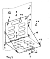
- Fig. 2 shows a schematic representation of the device 1 according to the invention in a front view in an unfolded position 16, for example attached to a metal wall 23, in particular a metal control cabinet door and / or wall, held by exemplary magnetic elements 6, for example three.
- the device 1 advantageously has an exemplary carrying recess 24, which enables safe carrying.
- the first holding device 2 and the second holding device 3 are connected, for example, by a stable holding cable 17, in particular a steel cable.
- Fig. 3 shows a schematic representation of the device 1 according to the invention in a folding position 22.
- the device 1 can, for example, including a notebook and / or laptop, be held or carried in the folded position 22 on a metal wall, not shown, with the aid of a magnet holder according to the invention, in particular the magnetic elements .
Landscapes
- Engineering & Computer Science (AREA)
- General Engineering & Computer Science (AREA)
- Mechanical Engineering (AREA)
- Theoretical Computer Science (AREA)
- Computer Hardware Design (AREA)
- Human Computer Interaction (AREA)
- Physics & Mathematics (AREA)
- General Physics & Mathematics (AREA)
- Casings For Electric Apparatus (AREA)
Abstract
Description
- Die Erfindung betrifft eine Vorrichtung zum Halten und/oder Transportieren nach dem Oberbegriff von Anspruch 1 und eine Verwendung einer Vorrichtung zum Halten und/oder Transportieren nach dem Oberbegriff von Anspruch 9 und ein Verfahren zum Betätigen einer Vorrichtung zum Halten und/oder Transportieren nach dem Oberbegriff von Anspruch 10.
- Bekannt ist es, dass beispielsweise in Werkstattumgebungen von gelegentlich dort tätigen Personen, beispielsweise Außendienstmitarbeitern, mitgebrachte Notebooks oder Laptops nicht geeignet abgestellt werden können, um diese ohne Beschädigung bedienen zu können. Man versucht, diese auf den wenigen ebenen Flächen abzustellen, oder hält und betätigt diese mit einer Hand oder setzt sie auf den Knien ab.
- Die Aufgabe der vorliegenden Erfindung ist es, eine sichere und zuverlässige Vorrichtung zum Halten und/oder Transportieren eines Notebooks und/oder Laptops bereitzustellen.
- Die Aufgabe wird gelöst durch eine Vorrichtung zum Halten und/oder Transportieren eines Notebooks und/oder Laptops, umfassend eine erste Halteeinrichtung zur Aufnahme des Notebooks, insbesondere mit einer oder mehrere Aufnahmesicherungen, eine zweite Halteeinrichtung, wobei die erste Halteinrichtung über eine Klappverbindung mit der zweiten Halteeinrichtung klappbar verbunden ist, wobei die zweite Halteeinrichtung eine Magnethalterung zur lösbaren Anbringung der zweiten Halteeinrichtung an einer insbesondere senkrechten Metallfläche aufweist.
- Durch die erfindungsgemäße Vorrichtung wird Personen das Arbeiten mit dem Notebook/Laptop in Werkstätten, auf Baustellen und ähnlichen Umgebungen wesentlich erleichtert. In Werkstätten liegen vielfältige Anbringungsmöglichkeiten vor, da die Personen in den meisten Fällen an Maschinen und Anlagen arbeiten, deren Schutzumhausungen, Türen, und Wände aus Stahlblech sind, insbesondere Schaltschrankseiten und/oder Schaltschranktüren. Die erfindungsgemäße Vorrichtung haftet durch die erfindungsgemäße Magneteinrichtung sicher und zuverlässig an beliebigen Flächen und nimmt das Notebook und/oder Laptop sicher auf. Der Bediener kann so ohne größeren Aufwand und in ergonomischer Höhe Arbeiten an der Anlage ausführen. Bei der erfindungsgemäßen Vorrichtung handelt es sich um ein Hilfsmittel beispielsweise für Monteure, Programmierer, Servicearbeiter, Elektriker, die mit einem Notebook und/oder Laptop Maschinen und Anlagen betreuen, auslesen, warten und oder programmieren. Ein Notebook und/oder Laptop, auch ein schwereres, kann darauf sicher abgestellt werden. So ist das Notebook und/oder Laptop an einem definierten Platz und nicht beispielsweise behelfsmäßig auf Kisten, Maschinen, Kartons oder auf den Knien der damit arbeitenden Personen oder anderen unsicheren und gefahranfälligen Gegenständen. Die Vorrichtung wiegt beispielhaft etwa 1,45 kg und das Notebook und/oder Laptop kann im zusammengeklappten Zustand in der Halterung verbleiben und zusammen verstaut und auch abgesichert transportiert werden.
- Die erfindungsgemäße Vorrichtung kann zuverlässig an die meisten Metallflächen mit ferromagnetischen metallischen Eigenschaften, insbesondere mit Eisen, Kobalt, Nickel und entsprechende magnetische Legierungen, gehalten werden, insbesondere magnetischen Flächen, insbesondere Schaltschrankseiten und/oder Schaltschranktüren. Die Vorrichtung wird zum Beispiel an einen Schaltschrank angeheftet und das Notebook und/oder Laptop kann darauf abgestellt werden. Die Magnetelemente sind beispielhaft vorteilhaft mit einem Gummischutzmantel versehen, um Kratzer an der beaufschlagten metallischen Trageoberfläche zu vermeiden und die Rutschfestigkeit zu verbessern. Die Halterung lässt sich mit geringer Kraft von der Haftfläche lösen, ermöglich aber ein sicheres und standfestes Bedienen des Notebooks und/oder Laptops. Die erste Halteeinrichtung und die zweite Halteeinrichtung können vorteilhaft aus Aluminium, Edelstahl oder Stahl o. ä. hergestellt werden.
- Vorteilhaft ist es, wenn die zweite Halteeinrichtung mehrere Magnetelemente aufweist, die über die zweite Halteeinrichtung verteilt angeordnet sind, insbesondere über eine Rückseite der zweiten Halteeinrichtung verteilt, insbesondere weiterhin Rutschhemmungselemente, insbesondere angeordnet auf den Magnetelementen.
- Vorteilhaft ist es, wenn die zweite Halteeinrichtung drei Magnetelemente aufweist, wobei ein erstes Magnetelement und ein zweites Magnetelement in einer oberen Bereich der Halteeinrichtung und ein drittes Magnetelement im Wesentlichen mittig in einem unteren Bereich der zweiten Halteeinrichtung angeordnet sind.
- Vorteilhaft ist es, wenn die Magnethalterung eine Haltekraft von etwa 225 N, insbesondere etwa mit drei Magnetelementen zu jeweils etwa 75 N aufweist und/oder die Magnethalterung insbesondere Neodym-Legierungsmagnete aufweist, insbesondere daraus besteht. Beispielhaft kann ein Notebook und/oder Laptop in der Größe von etwa 375 x 285 x 29 mm aufgenommen werden, jedoch auch Ausführungen in anderen Größen. Auch der Öffnungswinkel kann durch verschiedene Längen der Halteseile verändert werden. Die Außenmaße der Vorrichtung im zusammengeklappten Zustand sind beispielhaft 408 x 296 x 43,5 mm. An der Vorrichtung sind vorteilhaft 3 Magneten mit einer Haltekraft von jeweils beispielhaft 75 N angebracht, also in Summe 225 N, angebracht, ca. 23 kg Haltegewicht. Vorteilhaft ist der Einsatz starker Neodym-Legierungsmagnete vorgesehen.
- Vorteilhaft ist es, wenn an der ersten Halteeinrichtung und korrespondierend an der zweiten Halteeinrichtung zumindest an einer Schmalseite, insbesondere an zwei Schmalseiten jeweils ein Klapphalteelement zur Halterung der Klappverbindung in einer Aufklappposition vorgesehen ist, insbesondere zumindest an einer Schmalseite jeweils ein Halteseil, das an Seilhalterungen befestigt ist, vorgesehen ist, insbesondere ein Stahlsein.
- Vorteilhaft ist es, wenn die erste Halteeinrichtung eine Längsseite von etwa 370 - 400 mm, insbesondere etwa 375 mm, aufweist und eine Schmalseite von etwa 270 - 300 mm, insbesondere etwa 285 aufweist an einer Längsseite ein Sicherungselement zur Halterung des Notebooks aufweist.
- Vorteilhaft ist es, wenn die erste Halteeinrichtung und die zweite Halteeinrichtung korrespondierend abgestimmte Längsseiten und Schmalseiten aufweist, so dass eine Zusammenklappposition haltbar ist, insbesondere hochklappbar in einer Befestigungsposition, und/oder ist die die erste Halteeinrichtung und die zweite Halteeinrichtung aufgebaut aus Aluminium und/oder Edelstahl und/oder/oder Stahl.
- Vorteilhaft ist es, wenn als Klappverbindung Schraubelemente zwischen an der ersten Halteeinrichtung und korrespondierend an der zweiten Halteeinrichtung vorgesehen sind.
- Die Aufgabe wird gelöst durch eine Verwendung einer Vorrichtung zum Halten und/oder Transportieren eines Notebooks und/oder Laptops, umfassend eine erstes Halteeinrichtung zur Aufnahme des Notebooks, insbesondere mit einer oder mehrere Aufnahmesicherungen, eine zweite Halteeinrichtung, wobei die erste Halteinrichtung über eine Klappverbindung mit der zweiten Halteeinrichtung klappbar verbunden ist, wobei die zweite Halteeinrichtung eine Magnethalterung zur lösbaren Anbringung der zweiten Halteeinrichtung an einer insbesondere senkrechten Metallfläche aufweist, nach einem der Ansprüche 1 bis 8, zur Halterung und/oder Transport für tragbare Computereinrichtungen, insbesondere Notebooks und/oder Laptops.
- Die Aufgabe wird gelöst durch eine Verfahren nach einem der Ansprüche 1 bis 8, unter Verwendung einer Vorrichtung einer Vorrichtung nach Anspruch 9, zum Halten und/oder Transportieren eines Notebooks und/oder Laptops, umfassend eine erste Halteeinrichtung und eine zweite Halteeinrichtung, wobei die zweite Halteeinrichtung mittels einer Magnethalterung an einer insbesondere senkrechten Metallfläche angebracht wird, wobei die erste Halteinrichtung über eine Klappverbindung mit der zweiten Halteeinrichtung klappbar verbunden ist, und in die erste Halteeinrichtung das Notebook eingesetzt wird, insbesondere mit einer oder mehrere Aufnahmesicherungen, eine zweite Halteeinrichtung, wobei die Anbringung die zweite Halteeinrichtung durch Lösen der Magnethalterung abnehmbar ist.
- Weitere Merkmale und Vorteile der Erfindung ergeben sich aus den Ansprüchen und der nachstehenden Beschreibung, in der Ausführungsbeispiele des Gegenstands der Erfindung in Verbindung mit den Zeichnungen näher erläutert sind.
- Es zeigen:
- Fig. 1
- eine schematische Darstellung der erfindungsgemäßen Vorrichtung in einer Aufklappposition,
- Fig. 2
- eine schematische Darstellung der erfindungsgemäßen Vorrichtung und
- Fig. 3
- ein schematische Darstellung der erfindungsgemäßen Vorrichtung in einer Zusammenklappposition.
-
Fig. 1 zeigt eine schematische Darstellung der erfindungsgemäßen Vorrichtung 1 zum Halten und/oder Transportieren eines nicht dargestellten Notebooks und/oder Laptops in einer Rückansicht in einer Aufklappposition 16, umfassend eine erste Halteeinrichtung 2 zur Aufnahme des Notebooks, insbesondere mit einer oder mehrere Aufnahmesicherungen 20, eine zweite Halteeinrichtung 3, wobei die erste Halteinrichtung 2 über eine Klappverbindung 4 mit der zweiten Halteeinrichtung 3 klappbar verbunden ist, wobei die zweite Halteeinrichtung 3 eine Magnethalterung 5 zur lösbaren Anbringung der zweiten Halteeinrichtung 3 an einer insbesondere senkrechten Metallfläche aufweist, wobei die zweite Halteeinrichtung mehrere Magnetelemente 6 aufweist, die über die zweite Halteeinrichtung verteilt angeordnet sind, insbesondere über eine Rückseite 7 der zweiten Halteeinrichtung 3 verteilt, insbesondere weiterhin Rutschhemmungselemente, insbesondere angeordnet auf den Magnetelementen 6, wobei die zweite Halteeinrichtung 3 drei Magnetelemente 6 aufweist, wobei ein erstes Magnetelement 8 und ein zweites Magnetelement 9 in einer oberen Bereich 11 der Halteeinrichtung und ein drittes Magnetelement 10 im Wesentlichen mittig in einem unteren Bereich 12 der zweiten Halteeinrichtung 3 angeordnet sind. - Beispielhaft weist die Magnethalterung 5 eine Haltekraft von etwa 225 N auf, insbesondere etwa mit drei Magnetelementen 6 zu jeweils etwa 75 N aufweist und/oder die Magnethalterung 5 Neodym-Legierungsmagnete aufweist, insbesondere daraus besteht. Beispielhaft weist die erste Halteeinrichtung und die zweite Halteeinrichtung korrespondierend abgestimmte Längsseiten 18 und Schmalseiten 13, 14 auf, so dass ein Zusammenklappposition 22 haltbar ist, auch an der Schranktür, insbesondere ist die Vorrichtung mittels einer Tragausnehmung 24 tragbar, insbesondere hochklappbar in einer Befestigungsposition, und/oder ist die die erste Halteeinrichtung und die zweite Halteeinrichtung aufgebaut aus Aluminium und/oder Edelstahl und/oder/oder Stahl, wobei an der ersten Halteeinrichtung 2 und korrespondierend an der zweiten Halteeinrichtung 3 zumindest an einer Schmalseite 13, 14, insbesondere an zwei Schmalseiten 13, 14 jeweils ein Klapphalteelement 15 zur Halterung der Klappverbindung 4 in einer Aufklappposition 16 vorgesehen ist, insbesondere zumindest an einer Schmalseite 13, 14 jeweils ein Halteseil 17, das an Seilhalterungen 18, 19 befestigt ist, vorgesehen ist.
- Beispielhaft hat die erste Halteeinrichtung eine Längsseite 18 von etwa 370 - 400 mm, insbesondere etwa 375 mm, und eine Schmalseite 13, 14 von etwa 270 - 300 mm, insbesondere etwa 285 aufweist an einer Längsseite ein Sicherungselement zur Halterung des Notebooks aufweist.
-
Fig. 2 zeigt eine schematische Darstellung der erfindungsgemäßen Vorrichtung 1 in einer Vorderansicht in einer Aufklappposition 16, beispielhaft angesetzt an eine Metallwand 23, insbesondere eine metallische Schaltschranktür - und/oder -wand, gehalten durch beispielhafte Magnetelemente 6, beispielhaft drei. Vorteilhaft weist die Vorrichtung 1 eine beispielhafte Tragausnehmung 24 auf, die ein sicheres Tragen ermöglicht. Die erste Haltereinrichtung 2 und die zweite Halteeinrichtung 3 sind beispielhaft durch ein stabiles Halteseil 17 verbunden, insbesondere ein Stahlseil. -
Fig. 3 zeigt ein schematische Darstellung der erfindungsgemäßen Vorrichtung 1 in einer Zusammenklappposition 22. Die Vorrichtung 1 kann beispielhaft einschließlich eines Notebooks und/oder Laptops in der Zusammenklappposition 22 an einer nicht dargestellten Metallwand mit Hilfe einer erfindungsgemäßen Magnethalterung, insbesondere der Magnetelemente, gehalten werden oder auch getragen werden. -
- 1 Vorrichtung zum Halten und/oder Transportieren
- 2 erste Halteinrichtung
- 3 zweite Halteeinrichtung
- 4 Klappverbindung
- 5 Magnethalterung
- 6 Magnetelement
- 7 Rückseite
- 8 erstes Magnetelement
- 9 zweites Magnetelement
- 10 drittes Magnetelement
- 11 oberen Bereich
- 12 unteren Bereich
- 13 Schmalseite
- 14 Schmalseite
- 15 Klapphalteelement
- 16 Aufklappposition
- 17 Halteseil
- 18 Seilhalterung
- 19 Seilhalterung
- 20 Aufnahmesicherung
- 21 Schraubelement
- 22 Zusammenklappposition
- 23 Metallwand
- 24 Tragausnehmung
Claims (10)
- Vorrichtung (1) zum Halten und/oder Transportieren eines Notebooks und/oder Laptops,umfassendeine erste Halteeinrichtung (2) zur Aufnahme des Notebooks und/oder Laptops, insbesondere mit einer oder mehrerer Aufnahmesicherungen (20),eine zweite Halteeinrichtung (3),wobei die erste Halteinrichtung (2) über eine Klappverbindung (4) mit der zweiten Halteeinrichtung (3) klappbar verbunden ist,wobei die zweite Halteeinrichtung (3) eine Magnethalterung (5) zur lösbaren Anbringung der zweiten Halteeinrichtung (3) an einer insbesondere senkrechten Metallfläche aufweist.
- Vorrichtung nach Anspruch 1, dadurch gekennzeichnet, dass die zweite Halteeinrichtung mehrere Magnetelemente (6) aufweist, die über die zweite Halteeinrichtung verteilt angeordnet sind, insbesondere über eine Rückseite (7) der zweiten Halteeinrichtung (3) verteilt, insbesondere weiterhin Rutschhemmungselemente, insbesondere angeordnet auf den Magnetelementen (6).
- Vorrichtung nach Anspruch 1 oder 2, dass die zweite Halteeinrichtung (3) drei Magnetelemente (6) aufweist, wobei ein erstes Magnetelement (8) und ein zweites Magnetelement (9) in einer oberen Bereich (11) der Halteeinrichtung und ein drittes Magnetelement (10) im Wesentlichen mittig in einem unteren Bereich (12) der zweiten Halteeinrichtung (3) angeordnet sind.
- Vorrichtung nach einem der Ansprüche 1 bis 3, dadurch gekennzeichnet, dass die Magnethalterung (5) eine Haltekraft von etwa 225 N, insbesondere etwa mit drei Magnetelementen (6) zu jeweils etwa 75 N aufweist und/oder die Magnethalterung (5) insbesondere Neodym-Legierungsmagnete aufweist, insbesondere daraus besteht.
- Vorrichtung nach einem der Ansprüche 1 bis 5, dadurch gekennzeichnet, dass an der ersten Halteeinrichtung (2) und korrespondierend an der zweiten Halteeinrichtung (3) zumindest an einer Schmalseite (13, 14), insbesondere an zwei Schmalseiten (13, 14) jeweils ein Klapphalteelement (15) zur Halterung der Klappverbindung (4) in einer Aufklappposition (16) vorgesehen ist, insbesondere zumindest an einer Schmalseite (13, 14) jeweils ein Halteseil (17), das an Seilhalterungen (18, 19) befestigt ist, vorgesehen ist, insbesondere Stahlseile.
- Vorrichtung nach einem der Ansprüche 1 bis 5, dadurch gekennzeichnet, dass die erste Halteeinrichtung eine Längsseite (18) von etwa 370 - 400 mm, insbesondere etwa 375 mm, aufweist und eine Schmalseite (13, 14) von etwa 270 - 300 mm, insbesondere etwa 285 aufweist an einer Längsseite ein Sicherungselement zur Halterung des Notebooks aufweist.
- Vorrichtung nach einem der Ansprüche 1 bis 6, dadurch gekennzeichnet, dass die erste Halteeinrichtung und die zweite Halteeinrichtung korrespondierend abgestimmte Längsseiten (18) und Schmalseiten (13, 14) aufweist, so dass ein Zusammenklappposition (22) haltbar ist, insbesondere mittels einer Tragausnehmung (24) tragbar, insbesondere hochklappbar in einer Befestigungsposition, und/oder ist die die erste Halteeinrichtung und die zweite Halteeinrichtung aufgebaut aus Aluminium und/oder Edelstahl und/oder/oder Stahl.
- Vorrichtung nach einem der Ansprüche 1 bis 7, dadurch gekennzeichnet, dass als Klappverbindung (4) Schraubelemente (21) zwischen an der ersten Halteeinrichtung (2) und korrespondierend an der zweiten Halteeinrichtung (3) vorgesehen sind.
- Verwendung einer Vorrichtung (1) zum Halten und/oder Transportieren tragbare Computereinrichtung, insbesondere Notebooks und/oder Laptops, umfassend eine erstes Halteeinrichtung (2) zur Aufnahme des Notebooks und/oder Laptops, insbesondere mit einer oder mehrere Aufnahmesicherungen (20), eine zweite Halteeinrichtung (3), wobei die erste Halteinrichtung (2) über eine Klappverbindung (4) mit der zweiten Halteeinrichtung (3) klappbar verbunden ist, wobei die zweite Halteeinrichtung (3) eine Magnethalterung (5) zur lösbaren Anbringung der zweiten Halteeinrichtung (3) an einer insbesondere senkrechten Metallfläche aufweist, nach einem der Ansprüche 1 bis 8, zur Halterung und/oder Transport für tragbare Computereinrichtungen, insbesondere Notebooks und/oder Laptops.
- Verfahren nach einem der Ansprüche 1 bis 8, unter Verwendung einer Vorrichtung einer Vorrichtung (1) nach Anspruch 9, zum Halten und/oder Transportieren eines Notebooks und/oder Laptops, umfassend eine erste Halteeinrichtung (2) und eine zweite Halteeinrichtung (3),wobei die zweite Halteeinrichtung (3) mittels einer Magnethalterung (5) an einer insbesondere senkrechten Metallfläche angebracht wird, wobei die erste Halteinrichtung (2) über eine Klappverbindung (4) mit der zweiten Halteeinrichtung (3) klappbar verbunden ist,und in die erste Halteeinrichtung (2) das Notebook und/oder Laptop eingesetzt wird, insbesondere mit einer oder mehrere Aufnahmesicherungen (20),eine zweite Halteeinrichtung (3), wobei die Anbringung die zweite Halteeinrichtung (3) durch Lösen der Magnethalterung (5) abnehmbar ist.
Applications Claiming Priority (1)
| Application Number | Priority Date | Filing Date | Title |
|---|---|---|---|
| DE102022002962.6A DE102022002962A1 (de) | 2022-08-16 | 2022-08-16 | Vorrichtung zum Halten und/oder Transportieren, Verwendung und Verfahren |
Publications (2)
| Publication Number | Publication Date |
|---|---|
| EP4324356A1 true EP4324356A1 (de) | 2024-02-21 |
| EP4324356B1 EP4324356B1 (de) | 2025-05-21 |
Family
ID=87747755
Family Applications (1)
| Application Number | Title | Priority Date | Filing Date |
|---|---|---|---|
| EP23000114.1A Active EP4324356B1 (de) | 2022-08-16 | 2023-08-14 | Vorrichtung zum halten und/oder transportieren, verwendung und verfahren |
Country Status (2)
| Country | Link |
|---|---|
| EP (1) | EP4324356B1 (de) |
| DE (1) | DE102022002962A1 (de) |
Citations (3)
| Publication number | Priority date | Publication date | Assignee | Title |
|---|---|---|---|---|
| US6425560B1 (en) * | 2000-08-31 | 2002-07-30 | Casey M. Dembowiak | Magnetic mounting object holder and hook |
| KR200379953Y1 (ko) * | 2004-05-07 | 2005-03-28 | 목봉현 | 노트북컴퓨터용 가방 |
| US20160183392A1 (en) * | 2014-12-19 | 2016-06-23 | Amie Kelley | Electronic Device Holder |
-
2022
- 2022-08-16 DE DE102022002962.6A patent/DE102022002962A1/de active Pending
-
2023
- 2023-08-14 EP EP23000114.1A patent/EP4324356B1/de active Active
Patent Citations (3)
| Publication number | Priority date | Publication date | Assignee | Title |
|---|---|---|---|---|
| US6425560B1 (en) * | 2000-08-31 | 2002-07-30 | Casey M. Dembowiak | Magnetic mounting object holder and hook |
| KR200379953Y1 (ko) * | 2004-05-07 | 2005-03-28 | 목봉현 | 노트북컴퓨터용 가방 |
| US20160183392A1 (en) * | 2014-12-19 | 2016-06-23 | Amie Kelley | Electronic Device Holder |
Also Published As
| Publication number | Publication date |
|---|---|
| EP4324356B1 (de) | 2025-05-21 |
| DE102022002962A1 (de) | 2024-02-22 |
Similar Documents
| Publication | Publication Date | Title |
|---|---|---|
| DE202014105326U1 (de) | Werkzeugkasten und den besagten Werkzeugkasten beinhaltenden Werkzeugwagen | |
| DE102022002962A1 (de) | Vorrichtung zum Halten und/oder Transportieren, Verwendung und Verfahren | |
| DE202022002417U1 (de) | Vorrichtung zum Halten und/oder Transportieren | |
| DE202017104787U1 (de) | Kombination aus einer Ladeschale und einer Haltevorrichtung | |
| DE1071666B (de) | ||
| DE102007017333A1 (de) | Vorrichtung zur magnetischen Halterung von Gegenständen | |
| DE602006001049T2 (de) | Universalhalter | |
| DE4000318C2 (de) | ||
| DE829589C (de) | Klemmleiste fuer Zeichnungs-Haengeregistraturen | |
| CH632969A5 (de) | Kassette zur aufnahme von werkzeugen, insbesondere von bohrern. | |
| DE102019118075B3 (de) | Griffbeschlag mit klappbarer öse zum einhängen eines schulterriemens | |
| EP3534749A1 (de) | Halterung | |
| DE202023103786U1 (de) | Kombinierter Hängebügel und Werkzeughalter | |
| DE102022121190A1 (de) | Aufhängvorrichtung zum aufhängen von tauchausrüstung | |
| DE7902560U1 (de) | Leitersicherungshaken | |
| DE29510665U1 (de) | Vorrichtung zur Festlegung von Gewehren | |
| DE102022109594A1 (de) | Halterungsanordnung für Zettelplatten; Gefahrguttransporter, Gefahrgutbehälter oder Gefahrgutcontainer | |
| DE102020131526A1 (de) | Vorrichtung zum Verbinden von elektronischen Geräten | |
| DE202023103275U1 (de) | Aufsatzeinrichtung für Halterungen von Blick- und Sonnenschutzeinrichtungen in Form einer selbstklebenden Lochplatte | |
| DE9209644U1 (de) | Tragbares Gehäuse mit Halteklammer | |
| DE202012003245U1 (de) | Kabelordnungsvorrichtung zum Ordnen von mehreren Kabeln | |
| DE29508263U1 (de) | Vorrichtung zur Durchführung von Deckentapezierarbeiten | |
| DE202013007863U1 (de) | Werkzeug zum Entfernen eines Teils | |
| DE9105142U1 (de) | Griffelhalter | |
| DE202020103137U1 (de) | Erweiterbare Zwinge |
Legal Events
| Date | Code | Title | Description |
|---|---|---|---|
| PUAI | Public reference made under article 153(3) epc to a published international application that has entered the european phase |
Free format text: ORIGINAL CODE: 0009012 |
|
| STAA | Information on the status of an ep patent application or granted ep patent |
Free format text: STATUS: THE APPLICATION HAS BEEN PUBLISHED |
|
| AK | Designated contracting states |
Kind code of ref document: A1 Designated state(s): AL AT BE BG CH CY CZ DE DK EE ES FI FR GB GR HR HU IE IS IT LI LT LU LV MC ME MK MT NL NO PL PT RO RS SE SI SK SM TR |
|
| STAA | Information on the status of an ep patent application or granted ep patent |
Free format text: STATUS: REQUEST FOR EXAMINATION WAS MADE |
|
| 17P | Request for examination filed |
Effective date: 20240602 |
|
| RBV | Designated contracting states (corrected) |
Designated state(s): AL AT BE BG CH CY CZ DE DK EE ES FI FR GB GR HR HU IE IS IT LI LT LU LV MC ME MK MT NL NO PL PT RO RS SE SI SK SM TR |
|
| GRAP | Despatch of communication of intention to grant a patent |
Free format text: ORIGINAL CODE: EPIDOSNIGR1 |
|
| STAA | Information on the status of an ep patent application or granted ep patent |
Free format text: STATUS: GRANT OF PATENT IS INTENDED |
|
| RIC1 | Information provided on ipc code assigned before grant |
Ipc: F16M 11/10 20060101ALI20241120BHEP Ipc: A45C 11/00 20060101ALI20241120BHEP Ipc: F16M 11/20 20060101ALI20241120BHEP Ipc: F16M 13/02 20060101ALI20241120BHEP Ipc: A47B 23/04 20060101ALI20241120BHEP Ipc: G06F 1/16 20060101ALI20241120BHEP Ipc: A45C 13/10 20060101AFI20241120BHEP |
|
| INTG | Intention to grant announced |
Effective date: 20241213 |
|
| GRAS | Grant fee paid |
Free format text: ORIGINAL CODE: EPIDOSNIGR3 |
|
| GRAA | (expected) grant |
Free format text: ORIGINAL CODE: 0009210 |
|
| STAA | Information on the status of an ep patent application or granted ep patent |
Free format text: STATUS: THE PATENT HAS BEEN GRANTED |
|
| AK | Designated contracting states |
Kind code of ref document: B1 Designated state(s): AL AT BE BG CH CY CZ DE DK EE ES FI FR GB GR HR HU IE IS IT LI LT LU LV MC ME MK MT NL NO PL PT RO RS SE SI SK SM TR |
|
| REG | Reference to a national code |
Ref country code: GB Ref legal event code: FG4D Free format text: NOT ENGLISH |
|
| REG | Reference to a national code |
Ref country code: CH Ref legal event code: EP |
|
| REG | Reference to a national code |
Ref country code: DE Ref legal event code: R096 Ref document number: 502023001004 Country of ref document: DE |
|
| REG | Reference to a national code |
Ref country code: IE Ref legal event code: FG4D Free format text: LANGUAGE OF EP DOCUMENT: GERMAN |
|
| REG | Reference to a national code |
Ref country code: NL Ref legal event code: MP Effective date: 20250521 |
|
| PG25 | Lapsed in a contracting state [announced via postgrant information from national office to epo] |
Ref country code: PT Free format text: LAPSE BECAUSE OF FAILURE TO SUBMIT A TRANSLATION OF THE DESCRIPTION OR TO PAY THE FEE WITHIN THE PRESCRIBED TIME-LIMIT Effective date: 20250922 Ref country code: ES Free format text: LAPSE BECAUSE OF FAILURE TO SUBMIT A TRANSLATION OF THE DESCRIPTION OR TO PAY THE FEE WITHIN THE PRESCRIBED TIME-LIMIT Effective date: 20250521 Ref country code: FI Free format text: LAPSE BECAUSE OF FAILURE TO SUBMIT A TRANSLATION OF THE DESCRIPTION OR TO PAY THE FEE WITHIN THE PRESCRIBED TIME-LIMIT Effective date: 20250521 |
|
| PGFP | Annual fee paid to national office [announced via postgrant information from national office to epo] |
Ref country code: DE Payment date: 20250830 Year of fee payment: 3 |
|
| REG | Reference to a national code |
Ref country code: LT Ref legal event code: MG9D |
|
| PG25 | Lapsed in a contracting state [announced via postgrant information from national office to epo] |
Ref country code: GR Free format text: LAPSE BECAUSE OF FAILURE TO SUBMIT A TRANSLATION OF THE DESCRIPTION OR TO PAY THE FEE WITHIN THE PRESCRIBED TIME-LIMIT Effective date: 20250822 Ref country code: NO Free format text: LAPSE BECAUSE OF FAILURE TO SUBMIT A TRANSLATION OF THE DESCRIPTION OR TO PAY THE FEE WITHIN THE PRESCRIBED TIME-LIMIT Effective date: 20250821 |
|
| PGFP | Annual fee paid to national office [announced via postgrant information from national office to epo] |
Ref country code: MC Payment date: 20250822 Year of fee payment: 3 |
|
| PG25 | Lapsed in a contracting state [announced via postgrant information from national office to epo] |
Ref country code: NL Free format text: LAPSE BECAUSE OF FAILURE TO SUBMIT A TRANSLATION OF THE DESCRIPTION OR TO PAY THE FEE WITHIN THE PRESCRIBED TIME-LIMIT Effective date: 20250521 Ref country code: PL Free format text: LAPSE BECAUSE OF FAILURE TO SUBMIT A TRANSLATION OF THE DESCRIPTION OR TO PAY THE FEE WITHIN THE PRESCRIBED TIME-LIMIT Effective date: 20250521 |
|
| PG25 | Lapsed in a contracting state [announced via postgrant information from national office to epo] |
Ref country code: BG Free format text: LAPSE BECAUSE OF FAILURE TO SUBMIT A TRANSLATION OF THE DESCRIPTION OR TO PAY THE FEE WITHIN THE PRESCRIBED TIME-LIMIT Effective date: 20250521 |
|
| PGFP | Annual fee paid to national office [announced via postgrant information from national office to epo] |
Ref country code: BE Payment date: 20250820 Year of fee payment: 3 |
|
| PG25 | Lapsed in a contracting state [announced via postgrant information from national office to epo] |
Ref country code: HR Free format text: LAPSE BECAUSE OF FAILURE TO SUBMIT A TRANSLATION OF THE DESCRIPTION OR TO PAY THE FEE WITHIN THE PRESCRIBED TIME-LIMIT Effective date: 20250521 |
|
| PGFP | Annual fee paid to national office [announced via postgrant information from national office to epo] |
Ref country code: FR Payment date: 20250828 Year of fee payment: 3 Ref country code: AT Payment date: 20251020 Year of fee payment: 3 |
|
| PG25 | Lapsed in a contracting state [announced via postgrant information from national office to epo] |
Ref country code: RS Free format text: LAPSE BECAUSE OF FAILURE TO SUBMIT A TRANSLATION OF THE DESCRIPTION OR TO PAY THE FEE WITHIN THE PRESCRIBED TIME-LIMIT Effective date: 20250821 |
|
| PGFP | Annual fee paid to national office [announced via postgrant information from national office to epo] |
Ref country code: IE Payment date: 20250820 Year of fee payment: 3 |
|
| PG25 | Lapsed in a contracting state [announced via postgrant information from national office to epo] |
Ref country code: IS Free format text: LAPSE BECAUSE OF FAILURE TO SUBMIT A TRANSLATION OF THE DESCRIPTION OR TO PAY THE FEE WITHIN THE PRESCRIBED TIME-LIMIT Effective date: 20250921 |
|
| PG25 | Lapsed in a contracting state [announced via postgrant information from national office to epo] |
Ref country code: LV Free format text: LAPSE BECAUSE OF FAILURE TO SUBMIT A TRANSLATION OF THE DESCRIPTION OR TO PAY THE FEE WITHIN THE PRESCRIBED TIME-LIMIT Effective date: 20250521 |
|
| PG25 | Lapsed in a contracting state [announced via postgrant information from national office to epo] |
Ref country code: DK Free format text: LAPSE BECAUSE OF FAILURE TO SUBMIT A TRANSLATION OF THE DESCRIPTION OR TO PAY THE FEE WITHIN THE PRESCRIBED TIME-LIMIT Effective date: 20250521 Ref country code: SM Free format text: LAPSE BECAUSE OF FAILURE TO SUBMIT A TRANSLATION OF THE DESCRIPTION OR TO PAY THE FEE WITHIN THE PRESCRIBED TIME-LIMIT Effective date: 20250521 |
|
| PG25 | Lapsed in a contracting state [announced via postgrant information from national office to epo] |
Ref country code: CZ Free format text: LAPSE BECAUSE OF FAILURE TO SUBMIT A TRANSLATION OF THE DESCRIPTION OR TO PAY THE FEE WITHIN THE PRESCRIBED TIME-LIMIT Effective date: 20250521 |
|
| PG25 | Lapsed in a contracting state [announced via postgrant information from national office to epo] |
Ref country code: EE Free format text: LAPSE BECAUSE OF FAILURE TO SUBMIT A TRANSLATION OF THE DESCRIPTION OR TO PAY THE FEE WITHIN THE PRESCRIBED TIME-LIMIT Effective date: 20250521 |
|
| PG25 | Lapsed in a contracting state [announced via postgrant information from national office to epo] |
Ref country code: SK Free format text: LAPSE BECAUSE OF FAILURE TO SUBMIT A TRANSLATION OF THE DESCRIPTION OR TO PAY THE FEE WITHIN THE PRESCRIBED TIME-LIMIT Effective date: 20250521 |
|
| PG25 | Lapsed in a contracting state [announced via postgrant information from national office to epo] |
Ref country code: IT Free format text: LAPSE BECAUSE OF FAILURE TO SUBMIT A TRANSLATION OF THE DESCRIPTION OR TO PAY THE FEE WITHIN THE PRESCRIBED TIME-LIMIT Effective date: 20250521 |
|
| REG | Reference to a national code |
Ref country code: DE Ref legal event code: R097 Ref document number: 502023001004 Country of ref document: DE |
|
| PG25 | Lapsed in a contracting state [announced via postgrant information from national office to epo] |
Ref country code: RO Free format text: LAPSE BECAUSE OF FAILURE TO SUBMIT A TRANSLATION OF THE DESCRIPTION OR TO PAY THE FEE WITHIN THE PRESCRIBED TIME-LIMIT Effective date: 20250521 |
|
| PLBE | No opposition filed within time limit |
Free format text: ORIGINAL CODE: 0009261 |
|
| STAA | Information on the status of an ep patent application or granted ep patent |
Free format text: STATUS: NO OPPOSITION FILED WITHIN TIME LIMIT |
|
| REG | Reference to a national code |
Ref country code: CH Ref legal event code: L10 Free format text: ST27 STATUS EVENT CODE: U-0-0-L10-L00 (AS PROVIDED BY THE NATIONAL OFFICE) Effective date: 20260402 |
|
| PG25 | Lapsed in a contracting state [announced via postgrant information from national office to epo] |
Ref country code: LU Free format text: LAPSE BECAUSE OF NON-PAYMENT OF DUE FEES Effective date: 20250814 |
|
| 26N | No opposition filed |
Effective date: 20260224 |