EP4321780A1 - Soupape à tiroir, module comprenant une soupape et installation pour transporter des produits en vrac à soupapes - Google Patents
Soupape à tiroir, module comprenant une soupape et installation pour transporter des produits en vrac à soupapes Download PDFInfo
- Publication number
- EP4321780A1 EP4321780A1 EP23000110.9A EP23000110A EP4321780A1 EP 4321780 A1 EP4321780 A1 EP 4321780A1 EP 23000110 A EP23000110 A EP 23000110A EP 4321780 A1 EP4321780 A1 EP 4321780A1
- Authority
- EP
- European Patent Office
- Prior art keywords
- line
- slide
- valve
- pressure
- bulk material
- Prior art date
- Legal status (The legal status is an assumption and is not a legal conclusion. Google has not performed a legal analysis and makes no representation as to the accuracy of the status listed.)
- Pending
Links
- 239000013590 bulk material Substances 0.000 title claims abstract description 48
- 230000005540 biological transmission Effects 0.000 claims description 15
- 230000006835 compression Effects 0.000 claims description 12
- 238000007906 compression Methods 0.000 claims description 12
- 239000000463 material Substances 0.000 description 18
- 238000000034 method Methods 0.000 description 8
- 238000007789 sealing Methods 0.000 description 3
- 230000001154 acute effect Effects 0.000 description 1
- 238000006073 displacement reaction Methods 0.000 description 1
- 230000000694 effects Effects 0.000 description 1
- 230000009969 flowable effect Effects 0.000 description 1
- 239000008187 granular material Substances 0.000 description 1
- 238000004519 manufacturing process Methods 0.000 description 1
- 239000000843 powder Substances 0.000 description 1
- 230000008439 repair process Effects 0.000 description 1
- 238000011144 upstream manufacturing Methods 0.000 description 1
Images


Classifications
-
- B—PERFORMING OPERATIONS; TRANSPORTING
- B65—CONVEYING; PACKING; STORING; HANDLING THIN OR FILAMENTARY MATERIAL
- B65G—TRANSPORT OR STORAGE DEVICES, e.g. CONVEYORS FOR LOADING OR TIPPING, SHOP CONVEYOR SYSTEMS OR PNEUMATIC TUBE CONVEYORS
- B65G53/00—Conveying materials in bulk through troughs, pipes or tubes by floating the materials or by flow of gas, liquid or foam
- B65G53/34—Details
- B65G53/40—Feeding or discharging devices
- B65G53/46—Gates or sluices, e.g. rotary wheels
-
- F—MECHANICAL ENGINEERING; LIGHTING; HEATING; WEAPONS; BLASTING
- F16—ENGINEERING ELEMENTS AND UNITS; GENERAL MEASURES FOR PRODUCING AND MAINTAINING EFFECTIVE FUNCTIONING OF MACHINES OR INSTALLATIONS; THERMAL INSULATION IN GENERAL
- F16K—VALVES; TAPS; COCKS; ACTUATING-FLOATS; DEVICES FOR VENTING OR AERATING
- F16K3/00—Gate valves or sliding valves, i.e. cut-off apparatus with closing members having a sliding movement along the seat for opening and closing
- F16K3/02—Gate valves or sliding valves, i.e. cut-off apparatus with closing members having a sliding movement along the seat for opening and closing with flat sealing faces; Packings therefor
- F16K3/0254—Gate valves or sliding valves, i.e. cut-off apparatus with closing members having a sliding movement along the seat for opening and closing with flat sealing faces; Packings therefor being operated by particular means
-
- F—MECHANICAL ENGINEERING; LIGHTING; HEATING; WEAPONS; BLASTING
- F16—ENGINEERING ELEMENTS AND UNITS; GENERAL MEASURES FOR PRODUCING AND MAINTAINING EFFECTIVE FUNCTIONING OF MACHINES OR INSTALLATIONS; THERMAL INSULATION IN GENERAL
- F16K—VALVES; TAPS; COCKS; ACTUATING-FLOATS; DEVICES FOR VENTING OR AERATING
- F16K3/00—Gate valves or sliding valves, i.e. cut-off apparatus with closing members having a sliding movement along the seat for opening and closing
- F16K3/02—Gate valves or sliding valves, i.e. cut-off apparatus with closing members having a sliding movement along the seat for opening and closing with flat sealing faces; Packings therefor
-
- F—MECHANICAL ENGINEERING; LIGHTING; HEATING; WEAPONS; BLASTING
- F16—ENGINEERING ELEMENTS AND UNITS; GENERAL MEASURES FOR PRODUCING AND MAINTAINING EFFECTIVE FUNCTIONING OF MACHINES OR INSTALLATIONS; THERMAL INSULATION IN GENERAL
- F16K—VALVES; TAPS; COCKS; ACTUATING-FLOATS; DEVICES FOR VENTING OR AERATING
- F16K31/00—Actuating devices; Operating means; Releasing devices
- F16K31/12—Actuating devices; Operating means; Releasing devices actuated by fluid
- F16K31/122—Actuating devices; Operating means; Releasing devices actuated by fluid the fluid acting on a piston
- F16K31/1221—Actuating devices; Operating means; Releasing devices actuated by fluid the fluid acting on a piston one side of the piston being spring-loaded
-
- F—MECHANICAL ENGINEERING; LIGHTING; HEATING; WEAPONS; BLASTING
- F16—ENGINEERING ELEMENTS AND UNITS; GENERAL MEASURES FOR PRODUCING AND MAINTAINING EFFECTIVE FUNCTIONING OF MACHINES OR INSTALLATIONS; THERMAL INSULATION IN GENERAL
- F16K—VALVES; TAPS; COCKS; ACTUATING-FLOATS; DEVICES FOR VENTING OR AERATING
- F16K31/00—Actuating devices; Operating means; Releasing devices
- F16K31/12—Actuating devices; Operating means; Releasing devices actuated by fluid
- F16K31/122—Actuating devices; Operating means; Releasing devices actuated by fluid the fluid acting on a piston
- F16K31/1223—Actuating devices; Operating means; Releasing devices actuated by fluid the fluid acting on a piston one side of the piston being acted upon by the circulating fluid
-
- F—MECHANICAL ENGINEERING; LIGHTING; HEATING; WEAPONS; BLASTING
- F16—ENGINEERING ELEMENTS AND UNITS; GENERAL MEASURES FOR PRODUCING AND MAINTAINING EFFECTIVE FUNCTIONING OF MACHINES OR INSTALLATIONS; THERMAL INSULATION IN GENERAL
- F16K—VALVES; TAPS; COCKS; ACTUATING-FLOATS; DEVICES FOR VENTING OR AERATING
- F16K31/00—Actuating devices; Operating means; Releasing devices
- F16K31/12—Actuating devices; Operating means; Releasing devices actuated by fluid
- F16K31/42—Actuating devices; Operating means; Releasing devices actuated by fluid by means of electrically-actuated members in the supply or discharge conduits of the fluid motor
-
- B—PERFORMING OPERATIONS; TRANSPORTING
- B65—CONVEYING; PACKING; STORING; HANDLING THIN OR FILAMENTARY MATERIAL
- B65G—TRANSPORT OR STORAGE DEVICES, e.g. CONVEYORS FOR LOADING OR TIPPING, SHOP CONVEYOR SYSTEMS OR PNEUMATIC TUBE CONVEYORS
- B65G2811/00—Indexing codes relating to common features for more than one conveyor kind or type
- B65G2811/06—Devices controlling the relative position of articles
- B65G2811/0647—Changing the direction of movement of articles or bulk material
- B65G2811/0652—Accessories
-
- F—MECHANICAL ENGINEERING; LIGHTING; HEATING; WEAPONS; BLASTING
- F16—ENGINEERING ELEMENTS AND UNITS; GENERAL MEASURES FOR PRODUCING AND MAINTAINING EFFECTIVE FUNCTIONING OF MACHINES OR INSTALLATIONS; THERMAL INSULATION IN GENERAL
- F16K—VALVES; TAPS; COCKS; ACTUATING-FLOATS; DEVICES FOR VENTING OR AERATING
- F16K3/00—Gate valves or sliding valves, i.e. cut-off apparatus with closing members having a sliding movement along the seat for opening and closing
- F16K3/02—Gate valves or sliding valves, i.e. cut-off apparatus with closing members having a sliding movement along the seat for opening and closing with flat sealing faces; Packings therefor
- F16K3/0281—Guillotine or blade-type valves, e.g. no passage through the valve member
-
- F—MECHANICAL ENGINEERING; LIGHTING; HEATING; WEAPONS; BLASTING
- F16—ENGINEERING ELEMENTS AND UNITS; GENERAL MEASURES FOR PRODUCING AND MAINTAINING EFFECTIVE FUNCTIONING OF MACHINES OR INSTALLATIONS; THERMAL INSULATION IN GENERAL
- F16K—VALVES; TAPS; COCKS; ACTUATING-FLOATS; DEVICES FOR VENTING OR AERATING
- F16K37/00—Special means in or on valves or other cut-off apparatus for indicating or recording operation thereof, or for enabling an alarm to be given
- F16K37/0025—Electrical or magnetic means
Definitions
- the invention relates to a slide valve according to claim 1, a module for producing a delivery line of a system for conveying bulk material according to claim 12 and a system for conveying bulk material according to the preamble of claim 13.
- Conveyor systems are known with which bulk material is conveyed from transmitters to receivers.
- the funding is carried out using negative pressure.
- the receivers can each be connected to at least two receivers via a delivery line. Blockages can occur in the outlets from the delivery lines to the receivers, which lead to delivery problems.
- the invention is based on the object of designing the slide valve, the module and the generic system in such a way that the bulk material can be reliably conveyed from the selected transmitter to the selected receiver.
- the slide valve according to the invention is characterized in that its slide is automatically adjusted depending on the prevailing pressure in the delivery line.
- the slide is connected to a piston which delimits a pressure chamber within a housing.
- the switching valve in the pressure transmission connection between the delivery line and the pressure chamber when opened, releases the pressure connection between the delivery line and the pressure chamber, then the pressure in the delivery line also prevails in the pressure chamber.
- Pressure means negative pressure and positive pressure.
- a negative pressure occurs in the pressure chamber, which causes the piston to be displaced by suction. Since the piston is connected to the slide, it is correspondingly moved from its closed position to its open position so that the material can flow through the delivery line.
- the piston is pushed away by the pressure prevailing in the pressure chamber, as a result of which the slide connected to it also moves from the closed to the open position.
- the slide is adjusted in good time before the material to be conveyed flows through the conveying line. This ensures that the material can flow unhindered through the delivery line.
- the slide is advantageously connected to the piston via at least one connecting piece.
- the connecting piece is preferably a piston rod that can be easily attached to the piston.
- the slide can be arranged at a sufficient distance from the piston so that the slide can be adjusted without any problems.
- This pressure transmission line is preferably connected to a switching valve with which the passage through the pressure transmission line can be opened or closed.
- the switching valve is located within a valve housing.
- the switching valve can be easily installed there and easily removed if necessary, for example for repairs.
- a second pressure transmission line is advantageously connected to the switching valve and is intended to be connected to the delivery line.
- the second pressure transmission line is connected to the interior of the delivery line, so that the pressure prevailing in the delivery line also prevails in the second pressure transmission line.
- the switching valve is opened so that the pressure prevailing in the second pressure transmission line prevails in the pressure chamber via the opened switching valve and the first pressure transmission line.
- the delivery line is advantageously provided with an opening through which the pressure prevailing in the delivery line can be transferred into the pressure chamber.
- the switching valve is preferably a solenoid valve that can be easily controlled, is compact and can be easily accommodated in the valve housing.
- limit switches are provided which can interact with the slide when it is Open and/or its closed position.
- the limit switches can be proximity switches.
- the slide valve is installed in a conveyor system in a vertical or almost vertical position, then the slider is returned to its closed position very simply by terminating the conveyance. This means there is no longer any pressure in the delivery line.
- the pressure difference between the delivery line and the pressure chamber is eliminated, so that the piston is moved downwards under its own weight, whereby the slide moves from the open to the closed position. Since the slide is connected to the piston, the weight of the slide also acts on the piston and its push-back movement.
- a restoring force advantageously acts on the piston in the open position of the slide.
- the pressure medium is advantageously a compression spring, which is adjusted so that the piston can be moved under the delivery pressure in the delivery line in order to move the slide into its open position.
- the restoring force can be generated by at least one restoring element that acts on the slide.
- Such a return element is advantageously an elastically stretchable or a weight-bearing pull rope.
- the elastically stretchable pull rope is stretched elastically in the open position of the slide, creating a restoring force acts on the piston via the slide.
- the tensile force of the pull cable is adjusted so that the piston can be reliably moved under the respective operating pressure prevailing in the delivery line. This also applies in the event that a weight hangs on the pull cable, which loads the slide and thus the piston in the return direction.
- the module according to the invention is used to put together the delivery line of a conveyor system for bulk goods.
- the module has a pipe section from which a tubular crosspiece branches off, in which a switching valve according to the invention sits.
- a switching valve according to the invention sits.
- two or more modules with their pipe sections are placed together, resulting in a continuous delivery line.
- the cross pieces are advantageously directed obliquely upwards from the pipe sections in the opposite direction of conveyance, so that any material located in the cross pieces after the end of a conveying cycle can reach downwards into the pipe section. It will be taken there for the next funding cycle. This reliably prevents blockages in the delivery line.
- the delivery lines between the transmitters and the receiver have at least one receiver manifold. It has an upward, for example vertical, line section into which at least two cross lines open. In each of them there is a switching valve according to the invention for opening and closing the line section.
- the cross lines lie at an acute angle to the line sections that run from top to bottom. This means that the bulk material to be conveyed can fall down into the line section at the end of a conveying cycle. The bulk material can be taken there during the next conveying cycle and delivered to the respective recipient.
- the upwardly extending line section is advantageously achieved by assembling two or more modules according to the invention with their pipe sections in a fluid-tight manner. These pipe sections When assembled, they form the line section of the receiver bus line.
- the number of modules determines the desired number of transmitters from which the bulk material is to be sent to the receivers.
- An empty suction module that has no connection to a transmitter is preferably arranged at the upper end of the cross line. This allows the receiver line to be vacuumed and cleaned after each conveying cycle, which is particularly necessary when changing materials.
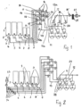
- Fig. 1 shows a system for conveying bulk materials.
- the system has, for example, five transmitters A to E, which are designed as silos where the bulk material is located.
- Bulk goods are understood to mean all flowable materials that can be transported using a gaseous medium, in particular air, such as granules, powders and the like.
- the transmitters A, B have a smaller capacity than the transmitters C to E. All transmitters can have the same capacity or different capacity.
- Each transmitter A to E has, for example, a cylindrical jacket 1, which merges into a jacket 2 that tapers downwards at the lower end. At the lower end of the jacket 2 there is an outlet opening 3, which can be closed by a valve 4. Such training is intended for pressure conveying of the bulk material.
- the jacket 2 has no outlet opening. Instead, a suction pipe protrudes through the jacket 2 into its interior, with which the bulk material can be sucked out.
- a transmitter line 5 to 9 is connected to the outlet opening 3 or to the suction pipe of each transmitter A to E. They can be connected to receiver lines 10 to 12 in order to supply the bulk material in transmitters A to E to receivers 1 to 3. For example, they sit on processing machines with which the supplied bulk material is processed accordingly.
- the transmitter lines 5 to 9 are firmly fluidly connected to the receiver lines 10 to 12. These lines are coupled together in such a way that receivers 1 to 3 can be coupled to different transmitters A to E.
- the transmitter line 5 is connected to the receiver line 12.
- a cross line 13 branches off from the transmitter line 5 and connects the transmitter line 5 to the receiver line 10.
- the transmitter line 6 is connected to the receiver line 12.
- the transmitter line 6 is also connected to the receiver lines 11, 10 via cross lines 15, 16.
- the transmitter line 7 is connected to the receiver line 11.
- the valve 14 is located in the transmitter line 7.
- the transmitter line 8 is connected to the receiver line 11 and to the receiver line 10 via a cross line 17. There is a valve 14 in the cross line 17 and in the transmitter line 8.
- the transmitter line 9 finally connects to the receiver line 10 and is provided with the valve 14.
- valves 14 it is easily possible to fill the receivers 1 to 3 with the desired bulk material from the transmitters A to E.
- receiver 1 is assigned to transmitters A, B, D and E.
- the bulk material can be fed from the transmitter A with the valve 14 open via the transmitter line 9 and the receiver line 10.
- the bulk material in the transmitter B can be conveyed via the transmitter line 8 and the cross line 17 into the receiver line 10 and from there to the receiver 1 with the valve open. In this case, of course, the valve 14 located in the transmitter line 9 is closed.
- the bulk material from the transmitter D can be fed to the receiver 1 via the transmitter line 6 and the cross line 16.
- the valve 14 located in the cross line 16 is open.
- the bulk material from the transmitter E can be conveyed via the transmitter line 5 and the cross line 13 into the receiver line 10 and from there to the receiver 1, with the valve 14 located in the cross line 13 being opened.
- the receiver 2 is assigned to the transmitters B, C and D.
- the bulk material in the transmitter B can reach the receiver line 11 via line 8 and from there into the receiver 2.
- the valve 14 located in the transmitter line 8 is open.
- the bulk material in the transmitter C can also be fed to the receiver 2 via the receiver line 11 via the transmitter line 7 with the valve 14 open.
- the transmitter D can also be fluidly connected to the receiver line 11 and thus to the receiver 2 via the transmitter line 6 and the cross line 15.
- the receiver 3 is assigned to the transmitters D and E.
- the bulk material from the transmitter D can be fed to the receiver 3 via the transmitter line 6 and the receiver line 12.
- the transmitter E can also be connected to the receiver 3 via the transmitter line 5 and the receiver line 12.
- the conveying function of the system is simple.
- the corresponding transmitters A to E are assigned to the receivers 1 to 3 by opening the corresponding valve 14.
- a suction line 18 to 20 is connected to each receiver 1 to 3 and is connected to a suction source 21. There is a valve 14 in each of the suction lines 18 to 20, so that the receivers 1 to 3 can optionally be separated from the suction source 21.
- the suction source 21 is preceded by a valve 14 ', with which the suction connection between the suction source 21 and all receivers 1 to 3 can be separated in the closed position.
- At least one filter 22 can be connected upstream of the suction source 21.
- the bulk material is sucked out of the respective transmitters A to E and fed to the respective receivers 1 to 3.
- the corresponding assigned valve 14 is opened.
- the corresponding valves 14 are switched so that the other material from the desired transmitter A to E can be fed to the corresponding receiver 1 to 3.
- the air flow is interrupted in a known manner.
- receiver lines 10 to 12 run upwards, vertically in the exemplary embodiment, in the area in which the transmitter lines or the cross lines connect (Receiver manifolds 10a to 12a), so that the bulk material in this area is conveyed from top to bottom.
- the vertically extending receiver manifolds 10a to 12a are composed of modules, each of which has a vertically extending pipe section, a vertically extending pipe section connected thereto and the valve 14, which is arranged in this transversely extending pipe section. These modules are explained in more detail below.
- the receiver manifolds 10a to 12a can also run obliquely and accordingly be arranged at an angle to the vertical.
- the number of these modules determines the desired number of transmitters A to E, whose material is to be assigned to receivers 1 to 3.
- the system according to Fig. 2 is designed in the same way as the system according to the linking of the transmitters A to E with the receivers 1 to 3 Fig. 1 .
- a pressure delivery system in which a pressure source 23 is used instead of a suction source. It conveys the bulk material from transmitters A to E under pressure through the corresponding lines to receivers 1 to 3.
- the transmitter lines 5 to 9 are each connected to the pressure source 23, which is preferably a compressed air source.
- the pressure source 23 which is preferably a compressed air source.
- each transmitter line 5 to 9 there is a valve 14, with which each transmitter line 5 to 9 can be separated from the pressure source 23.
- the valves 14 are located in the area between the respective outlet opening 3 of the transmitters A to E and the pressure source 23.
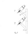
- the systems according to the 3 and 4 are basically designed in the same way as the systems according to Fig. 1 and 2 .
- planting according to Fig. 3 It is a suction conveyor system and the system is in accordance with Fig. 4 about a pressure conveyor system.
- a module 24 is marked with a dashed line, which is based on the Fig. 6 and 7 will be described in detail.
- the modules 24 are plugged together in a fluid-tight manner when the system is constructed.
- the systems are according to 3 and 4 For example, it is constructed in such a way that the receiver 1 is assigned the transmitters A, B, D and E, the receiver 2 is assigned the transmitters B, C, and D and the receiver 3 is assigned the transmitters D and E.
- valves 14 are located in oblique sections of the transverse lines 13, 15 to 17.
- the transverse lines 13, 15 to 17 each have a line section 13', 15' to 17' running parallel to the transmitter line 5 to 9, which runs via a line section running perpendicular to it into the line section 13a, 15a which runs obliquely downward and has the valve 14 to 17a passes.
- the transmitter line 9 with the associated line section 17 'of the cross line 17 forms a transmitter distribution line 25 that is oriented from bottom to top, which in Fig. 3 is represented by a dash-dotted line. All other transmitter lines 5 to 8 with the cross lines 13 ', 15', 16' each form another transmitter distribution line oriented from bottom to top.
- receiver lines 10 to 12 with the oblique line sections adjoining them and having the valves 14 each form a receiver manifold 26, as is indicated for the receiver line 10 with the oblique line sections connected to it by a dash-dotted line. Since three receiver lines 10 to 12 are provided in the exemplary embodiment, three receiver bus lines are also present.
- the receiver lines 10 to 12 are each provided with an empty suction module 27 at the free end.
- Each empty suction module 27 has a valve 14 that can be opened for the empty suction process and is not connected to a transmitter line.
- the transmitter distribution lines 25 and the receiver bus line 26 are provided in the same way. As in the previous embodiment, only one distribution or collecting line is shown.
- An exhaust air line 28 leads from each of the receivers 1 to 3 to the outside, via which the exhaust air can be removed.
- the exhaust air lines 28 are advantageously connected to a common collecting line 29.
- the exhaust air lines 28, 29 can, if necessary, be provided with valves or non-return flaps in order to be able to close these lines if necessary.
- connection between the transmitters A to E and the receivers 1 to 3 is essentially the same as in the system according to Fig. 3 . Since the facility according to Fig. 4 is a pressure conveying system, in contrast to the suction conveying system Fig. 3 no empty suction modules provided. While at the plant after Fig. 3 the bulk material in transmitters A to E is sucked off by means of the suction source 21 and fed to the receivers 1 to 3, according to the embodiment Fig. 4 the bulk material is fed to receivers 1 to 3 through a pressure medium.
- the suction conveyor system can be adjusted Fig. 3 After each suction process (conveying cycle), the receiver lines 10 to 12 must be vacuumed empty to the separator of the receiver 1 to 3 and thus cleaned. This is especially necessary when changing materials.
- the bulk material is conveyed in the receiver lines 26 from top to bottom.
- a conveyance from top to bottom is understood to mean both vertical conveyance and conveyance occurring at an angle obliquely to the vertical. This ensures that the remaining bulk material that is on Whatever remains in the pipes at the end of the conveying process is taken away during the next conveying cycle. In this way, the corresponding lines are prevented from becoming blocked by residual material left behind after the conveying cycle has been completed.
- Fig. 5 shows an example of a first embodiment of a module 24. It has a pipe section 30, from which a cross piece 31 branches off obliquely upwards. At the free end it merges into an end section 32 which runs perpendicular to the pipe section 30 and in which the valve 14 is arranged.
- the pipe sections 30 form parts of the receiver manifolds 26 in the system.
- the module 24 according to Fig. 6 and 7 also has the pipe section 30, which runs vertically in the installed position, from which the cross piece 31 branches off obliquely upwards.
- the valve 14 is located at the free end of this cross piece 31.
- This type of module is used in the systems according to 3 and 4 used.
- the modules 24 are plugged onto one another using the pipe sections 30 ( Fig. 7 ), which is the receiver bus line 26 ( 3 and 4 ) form.
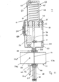
- the valve 14 is based on the Fig. 8 to 12 described in detail. It has a housing 33 which has side walls 34, 35 lying parallel to one another. At the upper end in the drawings, the side walls 34, 35 are connected to one another by an upper wall 36.
- the side walls 34, 35 are angled in such a way that they merge into bottom sections 37, 38, which are at the same height and parallel to the wall 36 and perpendicular to the side walls 34, 35.
- the bottom sections 37, 38 merge into holding parts 39, 40 which extend downwards at right angles and which run parallel to one another at a distance.
- the upper wall 36 is advantageously connected to the side walls 34, 35 as a separate component.
- the wall 36 is advantageously bent in a U-shape and its legs 41, 42 rest against the inside of the side walls 34, 35 and are firmly connected to them, for example screwed.
- a drive 43 is attached to the wall 36, with which a plate-shaped slide 44 can be adjusted to open and close the corresponding line 57.
- the slide 44 has a passage opening 44a, the diameter of which corresponds to the inner diameter of the line 57.
- the drive 43 has a housing 45 which projects through the wall 36 into the housing 33.
- the cylindrical housing 45 is fastened, preferably screwed, to the outside of the wall 36 with an annular flange 46.
- the annular flange 46 is part of a holding bushing 47, which passes through an opening 48 ( Fig. 11 ) in the wall 36 protrudes into the housing 33.
- the holding bushing 47 is attached to the outside of the housing 45.
- a piston 49 is slidably mounted in the cylindrical housing 45 ( Fig. 11 ).
- the slide 44 is firmly connected to the piston 49 via a connecting piece 50.
- An arm 51 protrudes transversely from the connecting piece 50, which protrudes close to the side wall 34 of the housing 33 and interacts with two limit switches 52, 53 which are provided on the inside of the side wall 34.
- the limit switches 52, 53 can differ from the illustrated embodiment on a circuit board 73 ( Fig. 8 and 9 ) may be arranged, which is arranged, for example, on the side wall 35 of the housing 33.
- a solenoid valve 54 is accommodated in the housing 33 of the valve 14 and is fastened in a suitable manner, for example, on the base section 37.
- the solenoid valve 54 is connected to the respective delivery line through a connecting hose 56 as a pressure transmission line, which is in the Fig. 8 to 12 is designated 57.
- the connecting hose 56 is fluidly connected to the interior of the delivery line 57, which has an opening 58 ( Fig. 11 ), to which the connecting hose 56 is connected. It is held on the delivery line 57, for example, by means of a clamp 59 ( Fig. 11 ).
- the solenoid valve 54 is fluidly connected to a cylinder space 61 in the housing 45 via a further connecting hose 60 as a pressure transmission line.
- the cylinder chamber 61 is located in the area between the piston 49 and a cover 62, which seals the cylinder chamber 61 in an airtight manner.
- the air inlet 63 is located near the underside of the lid 62 ( Fig. 11 ).
- the piston 49 also closes the cylinder space 61 in an almost airtight manner, so that it can be moved downwards without any problems.
- At least one compression spring 64 is accommodated in the cylinder chamber 61, which loads the piston 49 in the direction of the closed position of the slide 44 and which is supported on the cover 62.
- the compression spring 64 or a corresponding other pressure medium is not required for the function of the valve 14 if the valve 14 is installed in a vertical or almost vertical position. Then the piston 49 arrives due to its weight and the weight of the connecting piece 50 connected to it and the slide 44 down into the in Fig. 11 End position shown, in which the slide 44 closes the passage of the bulk material through the delivery line 57.
- annular sealing elements 65, 66 on both sides of the slide 44, which are formed, for example, by O-rings and seal the passage in the delivery line 57 for the slide 44 in an airtight manner.
- the sealing elements 65, 66 rest between the holding parts 39, 40 on the ends of the pipe sections 57a, 57b located between the holding parts 39, 40.
- a pipe section 57a, 57b is attached to the outer sides of the holding parts 39, 40 facing away from one another.
- the slider 44 is provided at the lower end with a stop 67 passing through it transversely ( Fig. 11 ). It is, for example, pin-shaped and projects into longitudinal slots 68, 69, which are provided in the two holding parts 39, 40. They are located at a distance on both sides of the slide 44, so that its displacement movement is not affected by the holding parts 39, 40.
- the stop 68 rests on the lower end of the longitudinal slots 68, 69 ( Fig. 8 and 11 ).
- the slide 44 is pulled up before the material delivery begins.
- the connecting line 56, 54, 60 from the delivery line 57 to the cylinder chamber 61, there is practically no air flow during the delivery process, since the negative pressure in the delivery line 57 is the same as the negative pressure in the cylinder chamber 61 as a result of the flow connection described.
- valve 14 If the valve 14 is activated during pressure delivery ( Fig. 2 and 4 ) is used, then the function is the same as with the suction conveying described. Only the valve 14 is then installed in the opposite position, as compared to Fig. 1 and 2 or 3 and 4 respectively.
- pressure conveying Fig. 1 and 3
- the valves 14 When pressure conveying ( Fig. 1 and 3 ), the valves 14 extend upwards from the respective line.
- pressure conveying Fig. 2 and 4
- the valves 14 extend downwards from the respective line.
- the pressure in the delivery line 57 which is effective in the cylinder chamber 61 via the described connecting line 56, 60, ensures that the piston 49 is displaced so that the slide 44 assumes its open position.
- the passage opening 44a is located at a different location on the slide 44 so that it can release or close the line 57. While the passage opening 44a is provided on the area of the slide 44 facing away from the piston 49 when used for suction delivery, the passage opening 44a is located on the area of the slide 44 adjacent to the piston 49 when the valve 14 is used for pressure delivery.
- the two end positions of the slide 44 are ensured in a simple manner by the stop 67 coming into contact with the two ends of the longitudinal slots 68, 69.
- the arm 51 which projects transversely from the connecting piece 50, interacts with the respective limit switches 52, 53 in the open and closed positions. They are advantageously designed as proximity switches with which it can be monitored whether the valve 14 is open or closed. In the respective end position of the slide 44, a corresponding switching signal is delivered via the limit switches 52, 53, based on which it can be reliably determined that the slide 44 assumes its open or closed position.
- the compression spring 64 is not required when the valve 14 is installed vertically because the slide 44 always reaches its closed position when the solenoid valve 54 is not opened due to the described weight. Since the compression spring 64 is compressed in the open position of the slide 44 ( Fig. 12 ), it supports the downward movement of the piston 49 when the slide 44 is to be moved into its closed position.
- the compression spring 64 ensures that the piston 49 is reliably moved in order to move the slide 44 from its open position to its closed position. In particular if the valve 14 should be installed horizontally, the compression spring 64 is required.
- the compression spring 64 is advantageously slightly pretensioned when the piston 49 is in a position in which the slide 44 closes the delivery line 57. The spring force is adjusted so that the piston 49 can be moved in any case when the slide 44 needs to be moved into its closed position.
- any other suitable pressure medium can also be used, for example pneumatic medium.
- valves 14 can be actuated in a simple manner, so that the bulk material from the respective transmitter A to E can be sent to the Recipients 1 to 3 can be funded.
- the required valves 14 can be opened in the manner described. Only those valves 14 are opened that are required to convey the bulk material from the selected transmitters A to E to the selected receivers 1 to 3. In this way, it is particularly easy to change the transmitter and/or the receiver and/or the type of bulk material.
- the valve 14 has a simple structural design and can be manufactured inexpensively.
- By means of the connecting hoses 56, 60 a simple yet reliable flow connection between the cylinder chamber 61 and the delivery line 57 is ensured when the solenoid valve 54 is open.
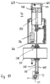
- Fig. 13 shows another embodiment of a valve. It is designed in such a way that it can be installed obliquely or horizontally in the respective delivery line without using a pressure medium, such as the compression spring 64 of the previous exemplary embodiment.
- the slide 44 is connected to at least one return element 70, which in the exemplary embodiment is a pull rope that is deflected via a deflection roller 71.
- the return element 70 is, for example, provided with a weight (not shown) with which a restoring force is exerted on the slide 44 when it is in its position Fig. 13 shown open position.
- the restoring force can also be generated by the restoring element 30 being a rubber rope or the like, which is under tension in the open position of the slide 44.
- the deflection roller 71 is rotatably mounted on a carrier 72 which is attached to the free lower end of the holding parts 39, 40.
- valve 14 is designed in the same way as the previous embodiment.
- Fig. 13 shows the piston 49 in its upper position within the housing 43.
- the delivery line 57 is released by the slide 44 so that the bulk material can be conveyed.
- the bulk material is transported by a suction conveying process. It is transferred in the manner described as a result of the negative pressure in the delivery line 57 into the in Fig. 13 shown upper position shifted.
- the same pressure acts in the cylinder chamber 61 via the connecting hoses 56, 60 as in the delivery line 57, which is a negative pressure in the case of suction delivery. In the manner described, it causes the piston 49 to be moved into the upper position.
- the restoring force acting on the slide 44 and thus on the piston 49 via the return element 70 is adjusted so that the piston 49 can be displaced by the negative pressure effect.
- the return element 50 reliably ensures that the piston 49 is pushed back and the slide 4 reaches its closed position.
Landscapes
- Engineering & Computer Science (AREA)
- General Engineering & Computer Science (AREA)
- Mechanical Engineering (AREA)
- Filling Or Emptying Of Bunkers, Hoppers, And Tanks (AREA)
- Multiple-Way Valves (AREA)
- Sliding Valves (AREA)
- Fluid-Driven Valves (AREA)
Applications Claiming Priority (1)
| Application Number | Priority Date | Filing Date | Title |
|---|---|---|---|
| DE102022002961.8A DE102022002961A1 (de) | 2022-08-10 | 2022-08-10 | Schieberventil, Modul mit einem Ventil und Anlage zum Fördern von Schüttgut mit Ventilen |
Publications (1)
| Publication Number | Publication Date |
|---|---|
| EP4321780A1 true EP4321780A1 (fr) | 2024-02-14 |
Family
ID=87571393
Family Applications (1)
| Application Number | Title | Priority Date | Filing Date |
|---|---|---|---|
| EP23000110.9A Pending EP4321780A1 (fr) | 2022-08-10 | 2023-08-07 | Soupape à tiroir, module comprenant une soupape et installation pour transporter des produits en vrac à soupapes |
Country Status (5)
| Country | Link |
|---|---|
| US (1) | US20240051771A1 (fr) |
| EP (1) | EP4321780A1 (fr) |
| JP (1) | JP2024025720A (fr) |
| CN (1) | CN117585458A (fr) |
| DE (1) | DE102022002961A1 (fr) |
Citations (4)
| Publication number | Priority date | Publication date | Assignee | Title |
|---|---|---|---|---|
| US4269225A (en) * | 1977-12-16 | 1981-05-26 | Technomatic Ag | Safety valve assembly |
| DE102016107407A1 (de) * | 2015-11-03 | 2017-05-04 | Festo Ag & Co. Kg | Applikationsbasierte Steuerung einer Ventilscheibe |
| WO2017207101A1 (fr) * | 2016-06-03 | 2017-12-07 | Walter Kramer | Installation de manutention destinée à des produits en vrac, notamment des granulés plastique, et procédé de manutention de produits en vrac, notamment de granulés plastique |
| US20210341955A1 (en) * | 2020-04-30 | 2021-11-04 | Shandong Keyuan Water Supply And Drainage Equipment Engineering Co. Ltd. | Safety Device For Hydrodynamic Pressure Regulating Pipe Network |
Family Cites Families (3)
| Publication number | Priority date | Publication date | Assignee | Title |
|---|---|---|---|---|
| DE1108728B (de) | 1953-10-10 | 1961-06-15 | Mannesmann Ag | Selbsttaetige, druckluftbetaetigte Schalt-einrichtung fuer das Entleeren von Foerderwagen in einer Wagenkippvorrichtung |
| DE2219962C3 (de) | 1972-04-24 | 1974-11-14 | Franz Hoernstein Hebebuehnen, 7101 Biberach | Druckmittelbetätigtes Ventil zum Absperren einer Rohrleitung |
| DE4118560C1 (fr) | 1991-06-06 | 1992-09-10 | Alb. Klein Gmbh & Co. Kg, 5241 Niederfischbach, De |
-
2022
- 2022-08-10 DE DE102022002961.8A patent/DE102022002961A1/de active Pending
-
2023
- 2023-08-07 EP EP23000110.9A patent/EP4321780A1/fr active Pending
- 2023-08-08 US US18/446,307 patent/US20240051771A1/en active Pending
- 2023-08-08 JP JP2023129114A patent/JP2024025720A/ja active Pending
- 2023-08-10 CN CN202311004016.5A patent/CN117585458A/zh active Pending
Patent Citations (4)
| Publication number | Priority date | Publication date | Assignee | Title |
|---|---|---|---|---|
| US4269225A (en) * | 1977-12-16 | 1981-05-26 | Technomatic Ag | Safety valve assembly |
| DE102016107407A1 (de) * | 2015-11-03 | 2017-05-04 | Festo Ag & Co. Kg | Applikationsbasierte Steuerung einer Ventilscheibe |
| WO2017207101A1 (fr) * | 2016-06-03 | 2017-12-07 | Walter Kramer | Installation de manutention destinée à des produits en vrac, notamment des granulés plastique, et procédé de manutention de produits en vrac, notamment de granulés plastique |
| US20210341955A1 (en) * | 2020-04-30 | 2021-11-04 | Shandong Keyuan Water Supply And Drainage Equipment Engineering Co. Ltd. | Safety Device For Hydrodynamic Pressure Regulating Pipe Network |
Also Published As
| Publication number | Publication date |
|---|---|
| CN117585458A (zh) | 2024-02-23 |
| US20240051771A1 (en) | 2024-02-15 |
| JP2024025720A (ja) | 2024-02-26 |
| DE102022002961A1 (de) | 2024-02-15 |
Similar Documents
| Publication | Publication Date | Title |
|---|---|---|
| CH638748A5 (de) | Rohrpoststation. | |
| EP3082406B1 (fr) | Vanne de sécurité | |
| DE102006045450B4 (de) | Spritzvorrichtung zum Versprühen von Spritzmitteln sowie Verfahren zum Betreiben einer solchen Spritzvorrichtung | |
| DE2611537A1 (de) | Muellsauganlage | |
| DE102013012868A1 (de) | Kupplungspunkt sowie Kupplungsstation für eine pneumatische Förderanlage zur Förderung von Schüttgut | |
| DE2453950A1 (de) | Pneumatische foerderanlage | |
| EP2592026B1 (fr) | Installation d'acheminement par aspiration | |
| EP0379628B1 (fr) | Procédé de transport pneumatique de matières et dispositif de réglage de l'alimentation d'air | |
| DE2628811A1 (de) | Pneumatische foerderanlage fuer pulverfoermige und koernige gueter | |
| DE3323739C2 (de) | Vorrichtung zur Pfropfenförderung von Schüttgut | |
| DE3637701C2 (de) | Saugförderanlage | |
| DE2253751A1 (de) | Ventilanordnung | |
| DE4243327A1 (de) | Vorrichtung zum pneumatischen Fördern von Schüttgut | |
| EP3753877A1 (fr) | Installation de transport par aspiration pour matériau en vrac, en particulier granulés en matière plastique | |
| DE4118560C1 (fr) | ||
| EP4321780A1 (fr) | Soupape à tiroir, module comprenant une soupape et installation pour transporter des produits en vrac à soupapes | |
| EP0555821B1 (fr) | Dispositif de séparation de particules métalliques | |
| DE102009040320B4 (de) | Leersaugventil | |
| EP1719720B1 (fr) | Dispositif de contrôle pour une ventouse de préhension | |
| DE102020004386A1 (de) | Fördergerät für den Einsatz im Kunststoffbereich | |
| DE19752005A1 (de) | Vorrichtung und Verfahren zur Vermischung eines ersten Fluids mit einem zweiten Fluid | |
| EP0816266B1 (fr) | Procédé et dispositif pour remplir une conduite de transport en courant épais | |
| CH417469A (de) | Steuerung für pneumatische Fördervorrichtung | |
| EP3263957B1 (fr) | Soupape en ligne pouvant être raclée | |
| EP1050496B1 (fr) | Méthode et dispositif pour l'ouverture et la fermeture d'un tuyau de transport |
Legal Events
| Date | Code | Title | Description |
|---|---|---|---|
| STAA | Information on the status of an ep patent application or granted ep patent |
Free format text: STATUS: UNKNOWN |
|
| PUAI | Public reference made under article 153(3) epc to a published international application that has entered the european phase |
Free format text: ORIGINAL CODE: 0009012 |
|
| STAA | Information on the status of an ep patent application or granted ep patent |
Free format text: STATUS: THE APPLICATION HAS BEEN PUBLISHED |
|
| AK | Designated contracting states |
Kind code of ref document: A1 Designated state(s): AL AT BE BG CH CY CZ DE DK EE ES FI FR GB GR HR HU IE IS IT LI LT LU LV MC ME MK MT NL NO PL PT RO RS SE SI SK SM TR |