EP4318924A1 - Steuerungsverfahren, -vorrichtung und -system sowie speichermedium - Google Patents
Steuerungsverfahren, -vorrichtung und -system sowie speichermedium Download PDFInfo
- Publication number
- EP4318924A1 EP4318924A1 EP22806640.3A EP22806640A EP4318924A1 EP 4318924 A1 EP4318924 A1 EP 4318924A1 EP 22806640 A EP22806640 A EP 22806640A EP 4318924 A1 EP4318924 A1 EP 4318924A1
- Authority
- EP
- European Patent Office
- Prior art keywords
- load
- control device
- control
- control signal
- power supply
- Prior art date
- Legal status (The legal status is an assumption and is not a legal conclusion. Google has not performed a legal analysis and makes no representation as to the accuracy of the status listed.)
- Pending
Links
Images

Classifications
-
- H—ELECTRICITY
- H02—GENERATION; CONVERSION OR DISTRIBUTION OF ELECTRIC POWER
- H02M—APPARATUS FOR CONVERSION BETWEEN AC AND AC, BETWEEN AC AND DC, OR BETWEEN DC AND DC, AND FOR USE WITH MAINS OR SIMILAR POWER SUPPLY SYSTEMS; CONVERSION OF DC OR AC INPUT POWER INTO SURGE OUTPUT POWER; CONTROL OR REGULATION THEREOF
- H02M1/00—Details of apparatus for conversion
- H02M1/42—Circuits or arrangements for compensating for or adjusting power factor in converters or inverters
- H02M1/4208—Arrangements for improving power factor of AC input
- H02M1/4216—Arrangements for improving power factor of AC input operating from a three-phase input voltage
-
- H—ELECTRICITY
- H02—GENERATION; CONVERSION OR DISTRIBUTION OF ELECTRIC POWER
- H02H—EMERGENCY PROTECTIVE CIRCUIT ARRANGEMENTS
- H02H3/00—Emergency protective circuit arrangements for automatic disconnection directly responsive to an undesired change from normal electric working condition with or without subsequent reconnection ; integrated protection
- H02H3/20—Emergency protective circuit arrangements for automatic disconnection directly responsive to an undesired change from normal electric working condition with or without subsequent reconnection ; integrated protection responsive to excess voltage
-
- H—ELECTRICITY
- H02—GENERATION; CONVERSION OR DISTRIBUTION OF ELECTRIC POWER
- H02H—EMERGENCY PROTECTIVE CIRCUIT ARRANGEMENTS
- H02H1/00—Details of emergency protective circuit arrangements
- H02H1/0007—Details of emergency protective circuit arrangements concerning the detecting means
-
- H—ELECTRICITY
- H02—GENERATION; CONVERSION OR DISTRIBUTION OF ELECTRIC POWER
- H02H—EMERGENCY PROTECTIVE CIRCUIT ARRANGEMENTS
- H02H7/00—Emergency protective circuit arrangements specially adapted for specific types of electric machines or apparatus or for sectionalised protection of cable or line systems, and effecting automatic switching in the event of an undesired change from normal working conditions
- H02H7/16—Emergency protective circuit arrangements specially adapted for specific types of electric machines or apparatus or for sectionalised protection of cable or line systems, and effecting automatic switching in the event of an undesired change from normal working conditions for capacitors
-
- H—ELECTRICITY
- H02—GENERATION; CONVERSION OR DISTRIBUTION OF ELECTRIC POWER
- H02J—ELECTRIC POWER NETWORKS; CIRCUIT ARRANGEMENTS OR SYSTEMS FOR SUPPLYING OR DISTRIBUTING ELECTRIC POWER; SYSTEMS FOR STORING ELECTRIC ENERGY
- H02J9/00—Circuit arrangements for emergency or stand-by power supply, e.g. for emergency lighting
- H02J9/04—Circuit arrangements for emergency or stand-by power supply, e.g. for emergency lighting in which the distribution system is disconnected from the normal source and connected to a standby source
- H02J9/06—Circuit arrangements for emergency or stand-by power supply, e.g. for emergency lighting in which the distribution system is disconnected from the normal source and connected to a standby source with automatic change-over, e.g. UPS systems
- H02J9/062—Circuit arrangements for emergency or stand-by power supply, e.g. for emergency lighting in which the distribution system is disconnected from the normal source and connected to a standby source with automatic change-over, e.g. UPS systems for AC powered loads
-
- H—ELECTRICITY
- H02—GENERATION; CONVERSION OR DISTRIBUTION OF ELECTRIC POWER
- H02M—APPARATUS FOR CONVERSION BETWEEN AC AND AC, BETWEEN AC AND DC, OR BETWEEN DC AND DC, AND FOR USE WITH MAINS OR SIMILAR POWER SUPPLY SYSTEMS; CONVERSION OF DC OR AC INPUT POWER INTO SURGE OUTPUT POWER; CONTROL OR REGULATION THEREOF
- H02M1/00—Details of apparatus for conversion
- H02M1/08—Circuits specially adapted for the generation of control voltages for semiconductor devices incorporated in static converters
- H02M1/088—Circuits specially adapted for the generation of control voltages for semiconductor devices incorporated in static converters for the simultaneous control of series or parallel connected semiconductor devices
-
- H—ELECTRICITY
- H02—GENERATION; CONVERSION OR DISTRIBUTION OF ELECTRIC POWER
- H02M—APPARATUS FOR CONVERSION BETWEEN AC AND AC, BETWEEN AC AND DC, OR BETWEEN DC AND DC, AND FOR USE WITH MAINS OR SIMILAR POWER SUPPLY SYSTEMS; CONVERSION OF DC OR AC INPUT POWER INTO SURGE OUTPUT POWER; CONTROL OR REGULATION THEREOF
- H02M1/00—Details of apparatus for conversion
- H02M1/32—Means for protecting converters other than automatic disconnection
-
- H—ELECTRICITY
- H02—GENERATION; CONVERSION OR DISTRIBUTION OF ELECTRIC POWER
- H02M—APPARATUS FOR CONVERSION BETWEEN AC AND AC, BETWEEN AC AND DC, OR BETWEEN DC AND DC, AND FOR USE WITH MAINS OR SIMILAR POWER SUPPLY SYSTEMS; CONVERSION OF DC OR AC INPUT POWER INTO SURGE OUTPUT POWER; CONTROL OR REGULATION THEREOF
- H02M1/00—Details of apparatus for conversion
- H02M1/0083—Converters characterised by their input or output configuration
- H02M1/009—Converters characterised by their input or output configuration having two or more independently controlled outputs
-
- H—ELECTRICITY
- H02—GENERATION; CONVERSION OR DISTRIBUTION OF ELECTRIC POWER
- H02M—APPARATUS FOR CONVERSION BETWEEN AC AND AC, BETWEEN AC AND DC, OR BETWEEN DC AND DC, AND FOR USE WITH MAINS OR SIMILAR POWER SUPPLY SYSTEMS; CONVERSION OF DC OR AC INPUT POWER INTO SURGE OUTPUT POWER; CONTROL OR REGULATION THEREOF
- H02M7/00—Conversion of AC power input into DC power output; Conversion of DC power input into AC power output
- H02M7/02—Conversion of AC power input into DC power output without possibility of reversal
- H02M7/04—Conversion of AC power input into DC power output without possibility of reversal by static converters
- H02M7/12—Conversion of AC power input into DC power output without possibility of reversal by static converters using discharge tubes with control electrode or semiconductor devices with control electrode
- H02M7/21—Conversion of AC power input into DC power output without possibility of reversal by static converters using discharge tubes with control electrode or semiconductor devices with control electrode using devices of a triode or transistor type requiring continuous application of a control signal
- H02M7/217—Conversion of AC power input into DC power output without possibility of reversal by static converters using discharge tubes with control electrode or semiconductor devices with control electrode using devices of a triode or transistor type requiring continuous application of a control signal using semiconductor devices only
-
- H—ELECTRICITY
- H02—GENERATION; CONVERSION OR DISTRIBUTION OF ELECTRIC POWER
- H02M—APPARATUS FOR CONVERSION BETWEEN AC AND AC, BETWEEN AC AND DC, OR BETWEEN DC AND DC, AND FOR USE WITH MAINS OR SIMILAR POWER SUPPLY SYSTEMS; CONVERSION OF DC OR AC INPUT POWER INTO SURGE OUTPUT POWER; CONTROL OR REGULATION THEREOF
- H02M7/00—Conversion of AC power input into DC power output; Conversion of DC power input into AC power output
- H02M7/42—Conversion of DC power input into AC power output without possibility of reversal
- H02M7/44—Conversion of DC power input into AC power output without possibility of reversal by static converters
- H02M7/48—Conversion of DC power input into AC power output without possibility of reversal by static converters using discharge tubes with control electrode or semiconductor devices with control electrode
- H02M7/483—Converters with outputs that each can have more than two voltages levels
- H02M7/487—Neutral point clamped inverters
Definitions
- the present application relates to the technical field of power supply detection, and in particular to a control method, a control device, a control system and a storage medium.
- the three-phase power supply circuit can provide operating voltage for inverter compressors by means of full-bus loads and for direct current (DC) fans by means of half-bus loads.
- DC direct current
- the full-bus load and the half-bus load are working, if the full-bus load suddenly fails, the half-bus load cannot be controlled in time to stop working, this results in a serious shift in the mid-point potential of the capacitor in the working circuit, with the effect that the capacitor is prone to the over-voltage phenomenon, which will further cause damage to the storage capacitor.
- embodiments of the present application aim to provide a control method, circuit, system and device, which solves the current problem of being unable to quickly and timely control the half-bus load to stop operation when the full-bus load suddenly fails, and realizes a control method of quickly and timely controlling the half-bus load to stop operation, such that the probability of damage of the storage capacitor in the three-phase power supply circuit due to the over-voltage phenomenon is effectively reduced, the control efficiency of the three-phase four-wire power supply circuit is improved, and the fault rate of the power supply control circuit is reduced.
- a first aspect provides a control method, wherein the control method is applied to a first control device for managing a three-phase three-level power supply circuit, including:
- a second aspect provides a first control device, wherein the first control device includes: a processor and a target communication channel, wherein:
- a third aspect provides a control system, wherein the system includes: a three-phase three-level power supply circuit, a first load, a second load, a first control device and a second control device; wherein:
- a fourth aspect provides an air conditioning device, the air conditioning device includes a control system as mentioned above; the first load is a direct current fan load and the second load is a compressor load.
- a fifth aspect provides a storage medium, on which a control program is stored, the control program when executed by a processor implements any one of the control methods as mentioned above.
- the first control device determines a first control signal for instructing the first load connected to the three-phase three-level power supply circuit to stop operation when a target type of fault is monitored, and sends the first control signal to the second control device via the target communication channel.
- the first control device sends the first control signal for instructing the first load to stop operation to the second control device via the target communication channel, so as to cause the second control device to control the first load to stop operation, thereby solving the current problem of unable to quickly and timely control the half-bus load to stop operation when the full-bus load suddenly fails, and realizing a control method of quickly and timely controlling the half-bus load to stop operation, such that the probability of damage of the storage capacitor in the three-phase power supply circuit due to the over-voltage phenomenon is effectively reduced, the control efficiency of the three-phase four-wire power supply circuit is improved, and the fault rate of the power supply control circuit is reduced.
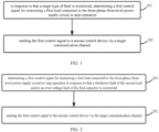
- Embodiments of the present application provide a control method, and as shown in FIG. 1 , the method is applied to a first control device for managing a three-phase three-level power supply circuit, the method includes: Step 101, in response to monitoring a target type of fault, determining a first control signal for instructing a first load connected to the three-phase three-level power supply circuit to stop operation.
- the first load is connected to one bus of the three-phase three-level power supply circuit, and the target type of fault has a correlation with a second load connected to two buses of the three-phase three-level power supply circuit.
- the target type of fault refers to a fault that would cause over-voltage or damage to an energy storage capacitor in the three-phase three-level power supply circuit.
- the first load may refer to a half-bus load, i.e., the first load is supplied with operating power from one bus in the three-phase three-level power supply circuit.
- a first control signal for controlling the first load to stop operation is generated immediately when the target type of fault is monitored.
- Step 102 sending the first control signal to a second control device via a target communication channel.
- the first control signal is configured to instruct the second control device to control the first load to stop operation.
- the target communication channel is a specific channel for sending the first control signal, which may be the original communication channel between the first control device and the second control device, or may be a dedicated communication channel for sending the first control signal.
- the second control device receives the first control signal and controls the first load to stop operation in response to the first control signal.
- the first control device determines a first control signal for instructing the first load connected to the three-phase three-level power supply circuit to stop operation when a target type of fault is monitored, and sends the first control signal to the second control device via the target communication channel.
- the first control device sends the first control signal for instructing the first load to stop operation to the second control device via the target communication channel, so as to cause the second control device to control the first load to stop operation, thereby solving the current problem of unable to quickly and timely control the half-bus load to stop operation when the full-bus load suddenly fails, and realizing a control method of quickly and timely controlling the half-bus load to stop operation, such that the probability of damage of the storage capacitor in the three-phase power supply circuit due to the over-voltage phenomenon is effectively reduced, the control efficiency of the three-phase four-wire power supply circuit is improved, and the fault rate of the power supply control circuit is reduced.
- the embodiment of the present application provides a control method, and as shown in FIG. 2 , the method is applied to a first control device for managing a three-phase three-level power supply circuit, and the method includes:
- Step 201 determining a first control signal for instructing a first load connected to the three-phase three-level power supply circuit to stop operation in response to that a shutdown fault of the second load and/or an over-voltage fault of the first capacitor is monitored.
- the first load is connected to one bus of the three-phase three-level power supply circuit
- the target type of fault has an association with the second load connected to two buses of the three-phase three-level power supply circuit
- the first capacitor is an energy storage capacitor in the three-phase three-level power supply circuit in addition to the second capacitor connected in parallel with the first load.
- the shutdown fault of the second load refers to that the second load has a sudden shutdown during normal operation
- the over-voltage fault of the first capacitor refers to a situation in which the voltage of the first capacitor is higher than the maximum withstand range of the first capacitor. Since the occurrence of the shutdown fault of the first load and/or the over-voltage fault of the first capacitor will lead to such as over-voltage or damage of the second capacitor, therefore, in order to protect the second capacitor, it is necessary to control the first load connected in parallel with the second capacitor to quickly stop operation, and thus cause the first load to stop consuming the voltage corresponding to the second capacitor, so as to ensure that the second capacitor does not experience an over-voltage or damage.
- Step 202 sending the first control signal to the second control device via the target communication channel.
- the first control signal is configured to instruct the second control device to control the first load to stop operation.
- the first control device quickly sends the generated first control signal to the second control device via the target communication channel between the first control device and the second control device, so that the second control device quickly responds to the first control signal to control the first load to stop operation.
- the target communication channel includes a wired communication channel or a wireless communication channel.
- the wireless communication channel may be realized by setting a matching wireless communication module in the first control device and the second control device.
- the circuit diagram of the three-phase three-level power supply circuit can be referred to as shown in FIG. 3 , specifically including: an alternating current (AC) input terminal 31, an inductor module 32, a rectifier module 33, and an energy storage module 34.
- AC alternating current
- the AC input terminal 31 includes: a first-phase AC input terminal A, a second-phase AC input terminal B, and a third-phase AC input terminal C, and the AC input terminal 31 connects to an externally input AC utility power;
- the inductor module 32 includes: three inductors L1, L2, and L3;
- the rectifier module 33 includes: six diodes D1, D2, D3, D4, D5, and D6, and six bi-directional switching tubes T1, T2, T3, T4, T5, and T6;
- the energy storage module 34 includes: two capacitors C1 and C2; and the bus E1 and the bus E2.
- the inductor module 32 transmits an AC voltage signal inputted from the AC input terminal 31 to the rectifier module 33, and the rectifier module 33 rectifies the received AC voltage signal to obtain a DC signal, and the DC signal is stored in the energy storage module 34.
- FIG. 4 A schematic diagram of the circuit connection between the three-phase three-level power supply circuit, the first control device, the second control device, the first load and the second load is shown in FIG. 4 or FIG. 5 , the first load is connected in parallel with the capacitor C1, the second load is connected in parallel with the capacitors C1 and C2, and the three-phase three-level power supply circuit provides the first load and the second load with the DC voltage.
- the first control device is used to monitor the three-phase three-level power supply circuit and manage and control the operating parameter of the second load, and control the second control device to control the operating parameter of the first load.
- FIG. 4 shows only one communication path F1 between the first control device and the second control device
- FIG. 5 shows two communication paths F2 and F3 between the first control device and the second control device.
- the communication path F2 is a dedicated channel for transmitting the first control signal
- the corresponding communication path F3 is configured for transmitting the second control signal that is sent from the first control device to the second control device to control the operating parameter of the first load.
- the capacitor C1 is the aforementioned first capacitor and the capacitor C2 is the aforementioned second capacitor.
- the first control signal is sent to the second control device via the target communication channel, which effectively improves the transmission efficiency of the first control signal, and ensures that the second control device can quickly receive the first control signal and respond to the first control signal to control the first load to stop operation, so that the first capacitor will not be over-voltage or damaged.
- the first control device determines a first control signal for instructing the first load connected to the three-phase three-level power supply circuit to stop operation when a target type of fault is monitored, and sends the first control signal to the second control device via the target communication channel.
- the first control device sends the first control signal for instructing the first load to stop operation to the second control device via the target communication channel, so as to cause the second control device to control the first load to stop operation, thereby solving the current problem of unable to quickly and timely control the half-bus load to stop operation when the full-bus load suddenly fails, and realizing a control method of quickly and timely controlling the half-bus load to stop operation, such that the probability of damage of the storage capacitor in the three-phase power supply circuit due to the over-voltage phenomenon is effectively reduced, the control efficiency of the three-phase four-wire power supply circuit is improved, and the fault rate of the power supply control circuit is reduced.
- the embodiment of the present application provides a control method, as shown in FIG. 6 , the method is applied to a first control device for managing a three-phase three-level power supply circuit, a transmission channel for transmitting a second control signal and a target communication channel are included between the first control device and the second control device, and the second control signal is a parameter of the first control device for controlling an operating parameter of a first load, the method includes:
- Step 401 determining a first control signal for instructing the first load connected to the three-phase three-level power supply circuit to stop operation in response to that a shutdown fault of the second load and/or an over-voltage fault of the first capacitor is monitored.
- the first load is connected to one bus of the three-phase three-level power supply circuit
- the target type of fault has a correlation with the second load connected to two buses of the three-phase three-level power supply circuit
- the first capacitor is an energy storage capacitor in the three-phase three-level power supply circuit in addition to the second capacitor connected in parallel with the first load.
- Step 402 in response to that the first control signal is in a form of a data frame, sending the first control signal to the second control device via the target communication channel according to a preset time interval.
- the preset time interval is less than a time period required for which a minimum operating voltage required by the first load is, when the first load is at its maximum, reduced to a minimum voltage permitted by a second capacitor connected in parallel with the first load, the first control signal is configured to instruct the second control device to control the first load to stop operation.
- the first control signal in the form of the data frame may be sent to the second control device via one target communication channel F2 that is used only for transmitting the first control signal, and the target communication channel F2 transmits the first control signal at a higher frequency.
- the preset time interval may be an empirical value obtained based on a large number of experiments that is less than the time period required for which the minimum operating voltage required by the first load is, when the first load is maximized, reduced to the minimum voltage permitted by the second capacitor connected in parallel with the first load, or a value obtained by a user based on the time period required for which the minimum operating voltage required for the first load is, when the first load is maximized, reduced to the minimum voltage permitted by the second capacitor connected in parallel with the first load.
- Both the first control device and the second control device may be a control chip, which may be, for example, a Microcontroller Unit (MCU).
- MCU Microcontroller Unit
- the first control signal may also be one form of: a high and low level signal and a voltage signal form.
- the form of the first control signal generated by the first control device may be at least one high and low level signal in addition to the form of a data frame, e.g., to illustrate as an example with a high level of 1 and a low level of 0.
- the first control device outputs a continuous high and low regularly changing level of 1010 whil to be sent to the second control device via a target communication channel, and the second control device receives the regular change level and immediately controls the first load to stop operation.
- the form of the voltage signal may be in the form of a voltage threshold, for example, when the second load, the second capacitor, and the first load are all working normally, the first control device may continuously output a high voltage threshold signal, for example, a voltage signal of 4V, via the target communication channel, and when the first control device monitors that there is a shutdown fault of the second load and/or an over-voltage fault of the first capacitor, the first control device turns the voltage signal output from the target communication channel into a low voltage threshold signal, such as a voltage signal of 1V, such that the first load is immediately controlled to stop operation when the second control device receives the voltage signal of 1V.
- a high voltage threshold signal for example, a voltage signal of 4V
- the target communication channel includes a wired communication channel or a wireless communication channel.
- the first control signal may be sent by the first control device to the second control device in the form of a wired form or a wireless signal.
- the use of a separately added target communication channel for transmitting various forms of the first control signal effectively ensures the efficiency of transmitting the first control signal, so that the first control signal can be quickly transmitted to the second control device, and the second control device can quickly control the first load to stop operation, and the first capacitor is effectively protected.
- the embodiment of the present application provides an application embodiment, which includes: a three-level rectifier circuit (namely, the foregoing three-phase three-level power supply circuit), a full-bus load (namely, the foregoing second load), a half-bus load (namely, the foregoing first load), a controller 1 (namely, the foregoing first control device), and a controller 2 (namely, the foregoing second control device); the controller 1 controls the full-bus load and the three-level rectifier circuit, and the controller 2 controls the half-bus load under the control of the controller 1.
- a three-level rectifier circuit namely, the foregoing three-phase three-level power supply circuit
- a full-bus load namely, the foregoing second load
- a half-bus load namely, the foregoing first load
- a controller 1 namely, the foregoing first control device
- a controller 2 namely, the foregoing second control device
- the controller 1 and the controller 2 have two communication lines 1 and 2.
- the communication line 1 is an additional communication line between the controller 1 and the controller 2, i.e. the aforementioned target communication channel.
- a time difference between adjacent data frames sent is less than a time interval 1; the time interval is less than the time required for the half-bus voltage to fall from the lowest control half-bus voltage to the lowest permissible voltage when the half-bus load is at its maximum.
- the communication line 1 is used only for transmitting signals for controlling the on-off of the half-bus load, such as the aforementioned first control signal for controlling the half-bus load to stop operation.
- the communication line 1 may be comprised of one or more communication lines.
- the first control signal be comprised of one or a set of high and low levels, or the first control signal may be distinguished by two voltage representations or two voltage thresholds, such as when the first control signal is less than 1V, it indicates that the half-bus load needs to be controlled to stop operation.
- the communication line 1 may be wireless communication.
- the communication line 2 is used to transmit other information such as speed control, speed feedback, etc. for controlling the half-bus load.
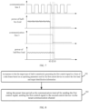
- the corresponding work timing diagram between the communication line 1, the communication line 2, the full-bus load, and the half-bus load may be shown as shown in FIG. 7 .
- the full-bus load has a shutdown fault at the moment 11
- the timing of sending the second control signal in the communication line 2 in the first control device does not change in any way, and the first control device generates the first control signal at the moment t2, and at the moment t2, the first control signal is sent to the second control device, and the second control device controls the half-bus load to stop operation when it receives the first control signal at the moment t3.
- the first control device determines a first control signal for instructing the first load connected to the three-phase three-level power supply circuit to stop operation when a target type of fault is monitored, and sends the first control signal to the second control device via the target communication channel.
- the first control device sends the first control signal for instructing the first load to stop operation to the second control device via the target communication channel, so as to cause the second control device to control the first load to stop operation, thereby solving the current problem of unable to quickly and timely control the half-bus load to stop operation when the full-bus load suddenly fails, and realizing a control method of quickly and timely controlling the half-bus load to stop operation, such that the probability of damage of the storage capacitor in the three-phase power supply circuit due to the over-voltage phenomenon is effectively reduced, the control efficiency of the three-phase four-wire power supply circuit is improved, and the fault rate of the power supply control circuit is reduced.
- embodiments of the present application provide a control method, as shown in FIG. 8 , the method is applied to manage a first control device of the three-phase three-level power supply circuit, and the target communication channel is also used to transmit an operating parameter of the first control device for controlling a first load, the method includes:
- Step 501 in response to monitoring the target type of fault, generating the first control signal in a form of a data frame based on an operating parameter of the first control device for controlling the first load and target identification information.
- the target identification information is used to instruct the second control device to control the second load to stop operation, and the target type of fault includes at least one of: a shutdown fault of the second load and an over-voltage fault of the first capacitor.
- the first capacitor is an energy storage capacitor in the three-phase three-level power supply circuit in addition to the second capacitor that is connected in parallel with the first load.
- the first control device monitors that neither the second load nor the first capacitor has a fault, i.e., they are working normally, the first control device generates a second control signal based on the operating parameter that controls the first load, and sends the second control signal to the second control device via the target communication channel according to a certain frequency of sending data frames, so that the second control device controls the operating parameter of the first load based on the operating parameters indicated by the second control signal.
- the first control device monitors a shutdown fault of the second load and/or an over-voltage fault of the first capacitor, the first control device generates the first control signal in the form of a data frame based on the operating parameter of the first load and the target identification information, which can be achieved specifically by that the first control device generates the second control signal based on the operating parameter of the first load, and adds the target identification information to a header or other position of the data frame of the second control signal to send the target identification information to the second control device.
- Step 502 taking the preset time period as the communication interval for sending the first control signal, sending the first control signal to the second control device via the target communication channel.
- the preset time period is less than a time period required for which a minimum operating voltage required by the first load is, when the first load is at its maximum, reduced to a minimum voltage permitted by a second capacitor connected in parallel with the first load, the first control signal is used to instruct the second control device to control the first load to stop operation.
- the preset period is an empirical value obtained based on a large number of experiments that is less than the time period required for which the minimum operating voltage required by the first load is, when the first load is at its maximum, reduced to the minimum voltage permitted by the second capacitor connected in parallel with the first load, and the preset period may also be a value of time determined by the user based on which the minimum operating voltage required by the first load is, when the first load is at its maximum, reduced to the minimum voltage permitted by the second capacitor connected in parallel with the first load.
- the preset time period is less than the sending interval for the first control device to send the second control signal, so that the first control device can quickly send the first control signal to the second control device to enable the second control device to quickly control the first load to stop operation, and the voltage between the first capacitor and the second capacitor is balanced before the second capacitor becomes over-voltage or damaged.
- the target communication channel includes a wired communication channel or a wireless communication channel.
- the first control signal can be quickly transmitted to the second control device by the target communication channel and the reduction of the transmission interval, so that the second control device can quickly control the first load to stop operation, the first capacitor is effectively protected.
- embodiments of the present application provide an application embodiment, which includes: a three-level rectifier circuit (namely, the foregoing three-phase three-level power supply circuit), a full-bus load (namely, the foregoing second load), a half-bus load (namely, the foregoing first load), a controller 1 (namely, the foregoing first control device), and a controller 2 (namely, the foregoing second control device); the controller 1 controls the full-bus load and the three-level rectifier circuit, and the controller 2 controls the half-bus load under the control of the controller 1.
- a three-level rectifier circuit namely, the foregoing three-phase three-level power supply circuit
- a full-bus load namely, the foregoing second load
- a half-bus load namely, the foregoing first load
- a controller 1 namely, the foregoing first control device
- a controller 2 namely, the foregoing second control device
- indication information for indicating the half-bus load to stop operation i.e. the aforementioned target identification information
- the controller 1 sends the first control signal to the controller 2 via the communication line 3 by a high baud rate and a short communication frame interval, so that the time for the controller 1 to send the longest frame is less than the time required for the half-bus voltage to fall from the lowest control half-bus voltage to the lowest permissible voltage when the half-bus load is at its maximum.
- the first control device determines a first control signal for instructing the first load connected to the three-phase three-level power supply circuit to stop operation when a target type of fault is monitored, and sends the first control signal to the second control device via the target communication channel.
- the first control device sends the first control signal for instructing the first load to stop operation to the second control device via the target communication channel, so as to cause the second control device to control the first load to stop operation, thereby solving the current problem of unable to quickly and timely control the half-bus load to stop operation when the full-bus load suddenly fails, and realizing a control method of quickly and timely controlling the half-bus load to stop operation, such that the probability of damage of the storage capacitor in the three-phase power supply circuit due to the over-voltage phenomenon is effectively reduced, the control efficiency of the three-phase four-wire power supply circuit is improved, and the fault rate of the power supply control circuit is reduced.
- embodiments of the present application provide a control method, as shown in FIG. 9 , the method is applied to a first control device that manages a three-phase three-level power supply circuit, and the target communication channel is also used to transmit an operating parameter of the first control device for controlling a first load, and the method includes:
- Step 601 in response to monitoring the target type of fault, generating the first control signal in a form of a data frame based on target identification information.
- the target identification information is used to instruct the second control device to control the second load to stop operation, the target type of fault includes at least one of: a shutdown fault of the second load and an over-voltage fault of the first capacitor, the first capacitor is an energy storage capacitor in the three-phase three-level power supply circuit in addition to the second capacitor connected in parallel with the first load.
- the first control device monitors that neither the second load nor the first capacitor has a fault, i.e., they are working normally, the first control device generates a second control signal based on the operating parameter of the first load, and sends the second control signal to the second control device via a target communication channel according to a certain frequency of sending data frames, so that the second control device controls the operating parameter of the first load based on the operating parameter indicated by the second control signal.
- the first control device monitors a shutdown fault of the second load and/or an over-voltage fault of the first capacitor, the first control device generates, based on the target identification information, the first control signal having only the target identification information, i.e., the first control device generates a separate control signal for instructing the second control device to control the first load to stop operation.
- Step 602 suspending the sending the second control signal via the target communication channel based on priorities of the first control signal and the second control signal.
- the sending priority of the first control signal is higher than the sending priority of the second control signal.
- the sending priority of the first control signal is set to the highest, and when the first control device generates the first control signal, the second control signal sent via the target communication channel is suspended due to the highest priority of the first control signal.
- Step 603 taking a preset time period as a communication interval for sending the first control signal, sending the first control signal to the second control device via the target communication channel.
- the preset time interval is less than a time period required for which a minimum operating voltage required by the first load is, when the first load is at its maximum, reduced to a minimum voltage permitted by a second capacitor connected in parallel with the first load, the first control signal is used to instruct the second control device to control the first load to stop operation.
- the first control device after the first control device suspends sending the second control signal, it sends the first control signal to the second control device via the target communication channel according to a preset time period communication interval.
- the target communication channel includes a wired communication channel or a wireless communication channel.
- the first control signal can be quickly transmitted to the second control device by the target communication channel and the reduction of the transmission interval, so that the second control device can quickly control the first load to stop operation, the first capacitor is effectively protected.
- embodiments of the present application provide an application embodiment, which includes: a three-level rectifier circuit (namely, the foregoing three-phase three-level power supply circuit), a full-bus load (namely, the foregoing second load), a half-bus load (namely, the foregoing first load), a controller 1 (namely, the foregoing first control device), and a controller 2 (namely, the foregoing second control device); the controller 1 controls the full-bus load and the three-level rectifier circuit, and the controller 2 controls the half-bus load under the control of the controller 1.
- a three-level rectifier circuit namely, the foregoing three-phase three-level power supply circuit
- a full-bus load namely, the foregoing second load
- a half-bus load namely, the foregoing first load
- a controller 1 namely, the foregoing first control device
- a controller 2 namely, the foregoing second control device
- indication information for indicating the half-bus load to stop operation i.e. the aforementioned target identification information
- the controller 1 sends the first control signal to the controller 2 via the communication line 3 by a high baud rate and a short communication frame interval, so that the time for the controller 1 to send the longest frame is less than the time required for the half-bus voltage to fall from the lowest control half-bus voltage to the lowest permissible voltage when the half-bus load is at its maximum.
- the first control device determines a first control signal for instructing the first load connected to the three-phase three-level power supply circuit to stop operation when a target type of fault is monitored, and sends the first control signal to the second control device via the target communication channel.
- the first control device sends the first control signal for instructing the first load to stop operation to the second control device via the target communication channel, so as to cause the second control device to control the first load to stop operation, thereby solving the current problem of unable to quickly and timely control the half-bus load to stop operation when the full-bus load suddenly fails, and realizing a control method of quickly and timely controlling the half-bus load to stop operation, such that the probability of damage of the storage capacitor in the three-phase power supply circuit due to the over-voltage phenomenon is effectively reduced, the control efficiency of the three-phase four-wire power supply circuit is improved, and the fault rate of the power supply control circuit is reduced.
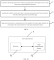
- the first control device 7 may include: a processor 71 and a target communication channel 72.
- the processor 71 is configured for in response to monitoring a target type of fault, determining a first control signal for instructing a first load connected to the three-phase three-level power supply circuit to stop operation; the first load is connected to one bus of the three-phase three-level power supply circuit, and the target type of fault has a correlation with a second load connected to two buses of the three-phase three-level power supply circuit.
- the target communication channel 72 is configured for communicating with a second control device to transmit the first control signal to the second control device; the first control signal is configured to instruct the second control device to control the second load to stop operation.
- the target type of fault includes at least one of: a shutdown fault of the second load and an over-voltage fault of the first capacitor; the first capacitor is an energy storage capacitor in the three-phase three-level power supply circuit in addition to the second capacitor connected in parallel with the first load.
- a transmission channel for transmitting a second control signal and a target communication channel are included between the first control device and the second control device, the second control signal includes an operating parameter of the first control device for controlling the first load, and the processor performs the step of sending the first control signal to the second control device via the target communication channel:
- the first control signal in response to that the first control signal is in a form of a data frame, sending the first control signal to the second control device via the target communication channel according to a preset time interval; the preset time interval is less than a time period required for which a minimum operating voltage required by the first load is, when the first load is at its maximum, reduced to a minimum voltage permitted by a second capacitor connected in parallel with the first load.
- the first control device and the second control device include a transmission channel and a target communication channel for transmitting the second control signal
- the second control signal includes an operating parameter of the first control device for controlling the first load
- the first control signal is further in one form of: a high and low level signal and a voltage signal form.
- the processor performing the step of determining the first control signal for instructing the first load connected to the three-phase three-level power supply circuit to stop operation in response to monitoring a target type of fault, which may be realized by the following steps:
- the processor when the processor performs the step of determining the first control signal for instructing the first load connected to the three-phase three-level power supply circuit to stop operation in response to monitoring the target type of fault, which may be realized by the following steps:
- the preset time period is less than a time period required for which a minimum operating voltage required by the first load is, when the first load is at its maximum, reduced to a minimum voltage permitted by a second capacitor connected in parallel with the first load.
- the target communication channel includes a wired communication channel or a wireless communication channel.
- the first control device determines a first control signal for instructing the first load connected to the three-phase three-level power supply circuit to stop operation when a target type of fault is monitored, and sends the first control signal to the second control device via the target communication channel.
- the first control device sends the first control signal for instructing the first load to stop operation to the second control device via the target communication channel, so as to cause the second control device to control the first load to stop operation, thereby solving the current problem of unable to quickly and timely control the half-bus load to stop operation when the full-bus load suddenly fails, and realizing a control method of quickly and timely controlling the half-bus load to stop operation, such that the probability of damage of the storage capacitor in the three-phase power supply circuit due to the over-voltage phenomenon is effectively reduced, the control efficiency of the three-phase four-wire power supply circuit is improved, and the fault rate of the power supply control circuit is reduced.
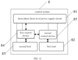
- control system 8 may include: a three-phase three-level power supply circuit 81, a first load 82, a second load 83, a first control device 84, and a second control device 85.
- the three-phase three-level power supply circuit 81 is configured to rectify the input AC electric signal to obtain a DC electric signal, and to provide an operating power supply for the first load 82 connected to one bus of the three-phase three-level power supply circuit, the second load 83 connected to two buses of the three-phase three-level power supply circuit, the first control device 84, and the second control device 85.
- the first control device 84 is configured to monitor the three-phase three-level power supply circuit and the first load, to realize the process of the method as shown in FIGS. 1-2 , FIGS. 6 , and FIGS. 8-9 , which will not be described in detail herein.
- a second control device 85 configured for managing and controlling the second load.
- the first control device 84 is the same device as the aforementioned first control device 7.
- the second control device 85 is usually under the control of the first control device 84 for performing management control of the second load.
- embodiments of the present application provide an air-conditioning device, the air-conditioning device is an air-conditioner including the control system shown in FIG. 11 , the first load is a DC fan load and the second load is a compressor load, which will not be described in detail herein.
- the second load i.e., the compressor load
- the first load i.e., the DC fan load
- the compressor load is operated with a power of 3,000 watts (W)
- the DC fan load is operated with a power of 100W. Since the power consumed by the DC fan load is much smaller compared to the power consumed by the compressor load. Therefore, in the case where the full-bus voltage supplies power to the main load, i.e., the compressor load, and the lower half-bus supplies power to the small load, i.e., the DC fan, the electrolytic capacitors C1 and C2 can both provide a power of 1,650 W.
- the upper half-bus capacitor i.e., the electrolytic capacitor C1
- the lower half-bus capacitor C2 can supply power of 1,550 W to the main load, i.e., the compressor load, while supplying power of 1,050 W to the DC fan load, at this time, a difference between the supply powers of the electrolytic capacitors C1 and C2 is smaller, the mid-point potential between the electrolytic capacitors C1 and C2 balances, the their respective voltages of the electrolytic capacitors C1 and C2 are also in their corresponding withstand voltage range.
- the first control device determines that the second load has stopped operation, it informs the second controller via the target communication channel that the second load has stopped operation and that the first load needs to be controlled to stop operation immediately, so that there is no load on both the upper half-bus and the lower half-bus, and the electrolytic capacitors C1 and C2 share the full-bus voltage equally, thereby ensuring that the electrolytic capacitors C1 will not be damaged. Due to the use of the target communication channel and the fast communication speed of the target communication channel, the master control responds in a timely manner, thereby ensuring that the capacitors are protected from damage.
- embodiments of the present application provide a computer-readable storage medium, referred to as a storage medium, which stores one or more programs, which can be executed by one or more processors to realize the control method provided by embodiments corresponding to FIGS. 1-2 , 6 , and 8-9 , which will not be repeated herein.
- Embodiments of the present application provide a control method device, system, and storage medium, the method includes: in response to monitoring a target type of fault, determining a first control signal for instructing a first load connected to the three-phase three-level power supply circuit to stop operation; the first load is connected to one bus of the three-phase three-level power supply circuit, and the target type of fault has a correlation with a second load connected to two buses of the three-phase three-level power supply circuit; sending the first control signal to a second control device via a target communication channel; the first control signal is configured to instruct the second control device to control the first load to stop operation.
- the first control device sends the first control signal for instructing the first load to stop operation to the second control device via the target communication channel, so as to cause the second control device to control the first load to stop operation, thereby solving the current problem of unable to quickly and timely control the half-bus load to stop operation when the full-bus load suddenly fails, and realizing a control method of quickly and timely controlling the half-bus load to stop operation, such that the probability of damage of the storage capacitor in the three-phase power supply circuit due to the over-voltage phenomenon is effectively reduced, the control efficiency of the three-phase four-wire power supply circuit is improved, and the fault rate of the power supply control circuit is reduced.
Landscapes
- Engineering & Computer Science (AREA)
- Power Engineering (AREA)
- Business, Economics & Management (AREA)
- Emergency Management (AREA)
- Remote Monitoring And Control Of Power-Distribution Networks (AREA)
Applications Claiming Priority (2)
| Application Number | Priority Date | Filing Date | Title |
|---|---|---|---|
| CN202110517405.2A CN115347808B (zh) | 2021-05-12 | 2021-05-12 | 一种控制方法、设备、系统及存储介质 |
| PCT/CN2022/091402 WO2022237674A1 (zh) | 2021-05-12 | 2022-05-07 | 一种控制方法、设备、系统及存储介质 |
Publications (2)
| Publication Number | Publication Date |
|---|---|
| EP4318924A1 true EP4318924A1 (de) | 2024-02-07 |
| EP4318924A4 EP4318924A4 (de) | 2024-10-02 |
Family
ID=83946945
Family Applications (1)
| Application Number | Title | Priority Date | Filing Date |
|---|---|---|---|
| EP22806640.3A Pending EP4318924A4 (de) | 2021-05-12 | 2022-05-07 | Steuerungsverfahren, -vorrichtung und -system sowie speichermedium |
Country Status (4)
| Country | Link |
|---|---|
| US (1) | US12525786B2 (de) |
| EP (1) | EP4318924A4 (de) |
| CN (1) | CN115347808B (de) |
| WO (1) | WO2022237674A1 (de) |
Families Citing this family (1)
| Publication number | Priority date | Publication date | Assignee | Title |
|---|---|---|---|---|
| CN115347808B (zh) * | 2021-05-12 | 2025-10-03 | 佛山市顺德区美的电子科技有限公司 | 一种控制方法、设备、系统及存储介质 |
Family Cites Families (28)
| Publication number | Priority date | Publication date | Assignee | Title |
|---|---|---|---|---|
| DE4435255A1 (de) * | 1994-10-01 | 1996-04-04 | Abb Management Ag | Verfahren zur Fehlerbehebung in einer Stromrichterschaltungsanordnung |
| US5805394A (en) * | 1997-06-17 | 1998-09-08 | Sundstrand Corporation | Overvoltage protection circuit for a generating system utilizing a fault current sensing Circuit in combination with a shunting circuit |
| KR100430930B1 (ko) * | 2000-02-25 | 2004-05-12 | 가부시끼가이샤 도시바 | Pwm 제어형 전력 변환 장치 |
| US8570779B2 (en) * | 2007-03-13 | 2013-10-29 | Siemens Aktiengesellschaft | Method for limiting damage to a converter having power semiconductors in the case of a short circuit in the DC voltage intermediate circuit |
| JP4431604B2 (ja) * | 2007-08-07 | 2010-03-17 | 日立アプライアンス株式会社 | コンバータ装置 |
| US8269451B2 (en) * | 2008-01-10 | 2012-09-18 | Mitsubishi Electric Corporation | Power conversion device |
| EP2355329B1 (de) * | 2008-12-01 | 2018-10-03 | Mitsubishi Electric Corporation | Wechselstrom - gleichstrom wandler und elektromotor treiber |
| US8203814B2 (en) * | 2009-08-31 | 2012-06-19 | Eaton Corporation | Electrical switching apparatus including a plurality of Rogowski coils and method of calibrating the same |
| CN105610312A (zh) * | 2011-11-11 | 2016-05-25 | 台达电子企业管理(上海)有限公司 | 一种级联型变频器及功率单元 |
| JP6032393B2 (ja) * | 2012-04-06 | 2016-11-30 | 富士電機株式会社 | 整流回路 |
| US20140347898A1 (en) * | 2012-05-31 | 2014-11-27 | General Electric Company | Modular multi-level power conversion system with dc fault current limiting capability |
| JP2013255317A (ja) | 2012-06-06 | 2013-12-19 | Meidensha Corp | 3レベルインバータの制御装置 |
| CN104253554A (zh) | 2013-06-26 | 2014-12-31 | 艾默生网络能源有限公司 | 一种逆变器和逆变器拓扑 |
| CN103837827B (zh) * | 2014-03-22 | 2017-01-18 | 中国科学院电工研究所 | 一种柔性直流输电阀的故障运行试验装置 |
| CN103983891B (zh) * | 2014-05-30 | 2018-10-09 | 台达电子企业管理(上海)有限公司 | 逆变器电路的短路故障检测装置及方法 |
| US10135237B2 (en) * | 2014-07-30 | 2018-11-20 | Abb Schweiz Ag | Systems and methods for exploiting current capability in static ups |
| KR101502578B1 (ko) * | 2014-10-15 | 2015-03-16 | 충남대학교산학협력단 | 전력선 통신 기반 부하 조절 장치 |
| US9797940B2 (en) * | 2014-12-29 | 2017-10-24 | Eaton Corporation | Arc fault detection system and method and circuit interrupter employing same |
| JP6659190B2 (ja) * | 2017-01-23 | 2020-03-04 | 三菱電機株式会社 | 電力変換装置、および電力変換システム |
| CN107499159A (zh) | 2017-08-14 | 2017-12-22 | 中国重汽集团济南动力有限公司 | 一种纯电动空压机的控制系统和控制方法 |
| EP3739347B1 (de) * | 2018-01-12 | 2024-03-13 | Hitachi Industrial Equipment Systems Co., Ltd. | Verfahren zur beurteilung eines spannungsungleichgewichts und stromwandler |
| CN210720695U (zh) * | 2019-08-08 | 2020-06-09 | 华侨大学 | T型三电平逆变器开路故障信息提取电路和故障诊断系统 |
| US11228243B2 (en) * | 2020-06-12 | 2022-01-18 | Dialog Semiconductor (Uk) Limited | Power converter with reduced RMS input current |
| CN212305171U (zh) * | 2020-09-30 | 2021-01-05 | 重庆美的制冷设备有限公司 | 电子电路和空调器 |
| CN112271700A (zh) | 2020-10-14 | 2021-01-26 | 珠海格力电器股份有限公司 | 母线电容的硬件保护装置、保护方法和一种用电电路 |
| CN115347808B (zh) * | 2021-05-12 | 2025-10-03 | 佛山市顺德区美的电子科技有限公司 | 一种控制方法、设备、系统及存储介质 |
| CN117353317A (zh) * | 2022-06-29 | 2024-01-05 | 佛山市顺德区美的电子科技有限公司 | 家电设备中全母线负载放电控制方法及相关装置 |
| CN117937918A (zh) * | 2022-10-24 | 2024-04-26 | 广州华凌制冷设备有限公司 | 电压控制方法、装置、家电设备及存储介质 |
-
2021
- 2021-05-12 CN CN202110517405.2A patent/CN115347808B/zh active Active
-
2022
- 2022-05-07 WO PCT/CN2022/091402 patent/WO2022237674A1/zh not_active Ceased
- 2022-05-07 US US18/289,529 patent/US12525786B2/en active Active
- 2022-05-07 EP EP22806640.3A patent/EP4318924A4/de active Pending
Also Published As
| Publication number | Publication date |
|---|---|
| CN115347808B (zh) | 2025-10-03 |
| US20240235178A1 (en) | 2024-07-11 |
| EP4318924A4 (de) | 2024-10-02 |
| CN115347808A (zh) | 2022-11-15 |
| US12525786B2 (en) | 2026-01-13 |
| WO2022237674A1 (zh) | 2022-11-17 |
Similar Documents
| Publication | Publication Date | Title |
|---|---|---|
| EP3487035A1 (de) | Stromversorgungssystem und -verfahren | |
| US9309887B2 (en) | System and method of remotely connecting and disconnecting the auxiliary power supply of a frequency inverter for variable capacity compressor employed in cooling systems | |
| US12126214B2 (en) | Uninterruptible power system and driving method for uninterruptible power system | |
| EP2755298A2 (de) | Energiesystem für Datenzentrum | |
| US12176751B2 (en) | Non-current equalization UPS apparatus, current distribution method, and parallel UPS system | |
| KR20150141315A (ko) | 인버터의 순간 정전 보상 방법 | |
| EP4318924A1 (de) | Steuerungsverfahren, -vorrichtung und -system sowie speichermedium | |
| CN114576796A (zh) | 用于控制空调系统的方法及装置、空调系统、存储介质 | |
| US20240186799A1 (en) | Power unit and solid-state transformer | |
| CN118868647A (zh) | 电源电路、电源控制方法及电子设备 | |
| CN109787292A (zh) | 一种多模块并机集中控制的光伏逆变器系统和控制方法 | |
| US9583974B1 (en) | Uninterruptible power supply for an electric apparatus | |
| CN209963947U (zh) | 一种空调器的供电电路、空调器电路及空调器 | |
| CN114123161B (zh) | 功率管理方法以及对应的控制装置和电气设备 | |
| CN223729497U (zh) | 一种切换电路及电源系统 | |
| US10073485B2 (en) | Method for compensating instantaneous power failure in medium voltage inverter and medium voltage inverter system using the same | |
| CN115395558B (zh) | 一种多类型变流器交流耦合系统 | |
| CN219937962U (zh) | 新能源控制系统 | |
| US12126175B2 (en) | Power supply control system and control method thereof | |
| CN217824739U (zh) | 一种开关电源的控制电路及空调器 | |
| CN211908370U (zh) | 数据中心供电系统 | |
| RU2813336C2 (ru) | Способ и устройство гибернации для источника питания, способ и устройство гибернации источника питания и аппарат гибернации | |
| CN114665787A (zh) | 变频器的能耗制动控制电路、变频器及能耗制动控制方法 | |
| CN104753323A (zh) | 一种变频器、变频器控制方法和控制装置 | |
| CN115241916A (zh) | 一种兼容多输入电压的变流装置及其自适应算法 |
Legal Events
| Date | Code | Title | Description |
|---|---|---|---|
| STAA | Information on the status of an ep patent application or granted ep patent |
Free format text: STATUS: THE INTERNATIONAL PUBLICATION HAS BEEN MADE |
|
| PUAI | Public reference made under article 153(3) epc to a published international application that has entered the european phase |
Free format text: ORIGINAL CODE: 0009012 |
|
| STAA | Information on the status of an ep patent application or granted ep patent |
Free format text: STATUS: REQUEST FOR EXAMINATION WAS MADE |
|
| 17P | Request for examination filed |
Effective date: 20231102 |
|
| AK | Designated contracting states |
Kind code of ref document: A1 Designated state(s): AL AT BE BG CH CY CZ DE DK EE ES FI FR GB GR HR HU IE IS IT LI LT LU LV MC MK MT NL NO PL PT RO RS SE SI SK SM TR |
|
| DAV | Request for validation of the european patent (deleted) | ||
| DAX | Request for extension of the european patent (deleted) | ||
| REG | Reference to a national code |
Ref country code: DE Ref legal event code: R079 Free format text: PREVIOUS MAIN CLASS: H02M0007483000 Ipc: H02H0007160000 |
|
| A4 | Supplementary search report drawn up and despatched |
Effective date: 20240904 |
|
| RIC1 | Information provided on ipc code assigned before grant |
Ipc: H02J 9/06 20060101ALI20240829BHEP Ipc: H02M 7/483 20070101ALI20240829BHEP Ipc: H02M 7/487 20070101ALI20240829BHEP Ipc: H02M 1/42 20070101ALI20240829BHEP Ipc: H02M 1/32 20070101ALI20240829BHEP Ipc: H02H 7/16 20060101AFI20240829BHEP |