EP4318080A2 - Optisches system für eine kopfmontierte anzeige - Google Patents
Optisches system für eine kopfmontierte anzeige Download PDFInfo
- Publication number
- EP4318080A2 EP4318080A2 EP23216531.6A EP23216531A EP4318080A2 EP 4318080 A2 EP4318080 A2 EP 4318080A2 EP 23216531 A EP23216531 A EP 23216531A EP 4318080 A2 EP4318080 A2 EP 4318080A2
- Authority
- EP
- European Patent Office
- Prior art keywords
- head
- lens element
- mounted display
- quarter wave
- polarizer
- Prior art date
- Legal status (The legal status is an assumption and is not a legal conclusion. Google has not performed a legal analysis and makes no representation as to the accuracy of the status listed.)
- Granted
Links
Images




Classifications
-
- G—PHYSICS
- G02—OPTICS
- G02B—OPTICAL ELEMENTS, SYSTEMS OR APPARATUS
- G02B17/00—Systems with reflecting surfaces, with or without refracting elements
- G02B17/08—Catadioptric systems
- G02B17/0856—Catadioptric systems comprising a refractive element with a reflective surface, the reflection taking place inside the element, e.g. Mangin mirrors
-
- G—PHYSICS
- G02—OPTICS
- G02B—OPTICAL ELEMENTS, SYSTEMS OR APPARATUS
- G02B27/00—Optical systems or apparatus not provided for by any of the groups G02B1/00 - G02B26/00, G02B30/00
- G02B27/01—Head-up displays
- G02B27/017—Head mounted
- G02B27/0172—Head mounted characterised by optical features
-
- G—PHYSICS
- G02—OPTICS
- G02B—OPTICAL ELEMENTS, SYSTEMS OR APPARATUS
- G02B27/00—Optical systems or apparatus not provided for by any of the groups G02B1/00 - G02B26/00, G02B30/00
- G02B27/28—Optical systems or apparatus not provided for by any of the groups G02B1/00 - G02B26/00, G02B30/00 for polarising
- G02B27/283—Optical systems or apparatus not provided for by any of the groups G02B1/00 - G02B26/00, G02B30/00 for polarising used for beam splitting or combining
-
- G—PHYSICS
- G02—OPTICS
- G02B—OPTICAL ELEMENTS, SYSTEMS OR APPARATUS
- G02B27/00—Optical systems or apparatus not provided for by any of the groups G02B1/00 - G02B26/00, G02B30/00
- G02B27/0018—Optical systems or apparatus not provided for by any of the groups G02B1/00 - G02B26/00, G02B30/00 with means for preventing ghost images
-
- G—PHYSICS
- G02—OPTICS
- G02B—OPTICAL ELEMENTS, SYSTEMS OR APPARATUS
- G02B27/00—Optical systems or apparatus not provided for by any of the groups G02B1/00 - G02B26/00, G02B30/00
- G02B27/28—Optical systems or apparatus not provided for by any of the groups G02B1/00 - G02B26/00, G02B30/00 for polarising
- G02B27/286—Optical systems or apparatus not provided for by any of the groups G02B1/00 - G02B26/00, G02B30/00 for polarising for controlling or changing the state of polarisation, e.g. transforming one polarisation state into another
-
- G—PHYSICS
- G09—EDUCATION; CRYPTOGRAPHY; DISPLAY; ADVERTISING; SEALS
- G09G—ARRANGEMENTS OR CIRCUITS FOR CONTROL OF INDICATING DEVICES USING STATIC MEANS TO PRESENT VARIABLE INFORMATION
- G09G3/00—Control arrangements or circuits, of interest only in connection with visual indicators other than cathode-ray tubes
- G09G3/001—Control arrangements or circuits, of interest only in connection with visual indicators other than cathode-ray tubes using specific devices not provided for in groups G09G3/02 - G09G3/36, e.g. using an intermediate record carrier such as a film slide; Projection systems; Display of non-alphanumerical information, solely or in combination with alphanumerical information, e.g. digital display on projected diapositive as background
- G09G3/003—Control arrangements or circuits, of interest only in connection with visual indicators other than cathode-ray tubes using specific devices not provided for in groups G09G3/02 - G09G3/36, e.g. using an intermediate record carrier such as a film slide; Projection systems; Display of non-alphanumerical information, solely or in combination with alphanumerical information, e.g. digital display on projected diapositive as background to produce spatial visual effects
-
- G—PHYSICS
- G02—OPTICS
- G02B—OPTICAL ELEMENTS, SYSTEMS OR APPARATUS
- G02B27/00—Optical systems or apparatus not provided for by any of the groups G02B1/00 - G02B26/00, G02B30/00
- G02B27/01—Head-up displays
- G02B27/0101—Head-up displays characterised by optical features
- G02B2027/0138—Head-up displays characterised by optical features comprising image capture systems, e.g. camera
Definitions
- This relates generally to optical systems and, more particularly, to optical systems for head- mounted displays.
- Head-mounted displays such as virtual reality glasses use lenses to display images for a user.
- a microdisplay may create images for each of a user's eyes.
- a lens may be placed between each of the user's eyes and a portion of the microdisplay so that the user may view virtual reality content.
- a head-mounted display may be cumbersome and tiring to wear.
- Optical systems for head-mounted displays may use arrangements of lenses that are bulky and heavy. Extended use of a head-mounted display with this type of optical system may be uncomfortable.
- a head-mounted display may include a display system and an optical system.
- the display system and optical system may be supported by a housing that is worn on a user's head.
- the head-mounted display may use the display system and optical system to present images to the user while the housing is being worn on the user's head.
- the display system may have a pixel array that produces image light associated with the images.
- the display system may also have a linear polarizer through which image light from the pixel array passes and a quarter wave plate through which the light passes after passing through the linear polarizer.
- the optical system may be a catadioptric optical system having one or more lens elements formed from clear materials such as glass or plastic and having reflective structures.
- the lens elements may include a plano-convex lens element and a planoconcave lens element.
- the plano-convex lens element may have a convex surface and an opposing planar surface.
- the plano-concave lens element may have a concave surface and an opposing planar surface that faces the planar surface of the convex lens element.
- a partially reflective mirror may be formed on a convex surface of the plano-convex lens element.
- a reflective polarizer may be formed on the planar surface of the plano-convex lens or the concave surface of the plano-concave lens.
- An additional quarter wave plate may be located between the reflective polarizer and the partially reflective mirror.
- Head-mounted displays may be used for virtual reality and augmented reality systems.
- a pair of virtual reality glasses that is worn on the head of a user may be used to provide a user with virtual reality content.
- FIG. 1 An illustrative system in which a head-mounted display such as a pair of virtual reality glasses is used in providing a user with virtual reality content is shown in FIG. 1 .
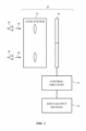
- virtual reality glasses (head-mounted display) 10 may include a display system such as display system 40 that creates images and may have an optical system such as optical system 20 through which a user (see, e.g., user's eyes 46) may view the images produced by display system 40 by looking in direction 48.
- Display system 40 may be based on a liquid crystal display, an organic light-emitting diode display, an emissive display having an array of crystalline semiconductor light-emitting diode dies, and/or displays based on other display technologies. Separate left and right displays may be included in system 40 for the user's left and right eyes or a single display may span both eyes.
- Visual content (e.g., image data for still and/or moving images) maybe provided to display system (display) 40 using control circuitry 42 that is mounted in glasses (head-mounted display) 10 and/or control circuitry that is mounted outside of glasses 42 (e.g., in an associated portable electronic device, laptop computer, or other computing equipment).
- Control circuitry 42 may include storage such as hard-disk storage, volatile and non-volatile memory, electrically programmable storage for forming a solid-state drive, and other memory.
- Control circuitry 42 may also include one or more microprocessors, microcontrollers, digital signal processors, graphics processors, baseband processors, application-specific integrated circuits, and other processing circuitry.
- Communications circuits in circuitry 42 may be used to transmit and receive data (e.g., wirelessly and/or over wired paths).
- Control circuitry 42 may use display system 40 to display visual content such as virtual reality content (e.g., computer-generated content associated with a virtual world), pre-recorded video for a movie or other media, or other images.
- virtual reality content e.g., computer-generated content associated with a virtual world
- pre-recorded video for a movie or other media e.g., pre-recorded video for a movie or other media, or other images.
- Illustrative configurations in which control circuitry 42 provides a user with virtual reality content using display system 40 may sometimes be described herein as an example. In general, however, any suitable content may be presented to a user by control circuitry 42 using display system 40 and optical system 20 of glasses 10.
- Input-output devices 44 may be coupled to control circuitry 42. Input-output devices 44 may be used to gather user input from a user, may be used to make measurements on the environment surrounding glasses 10, may be used to provide output to a user, and/or may be used to supply output to external electronic equipment.
- Input-output devices 44 may include buttons, joysticks, keypads, keyboard keys, touch sensors, track pads, displays, touch screen displays, microphones, speakers, light-emitting diodes for providing a user with visual output, sensors (e.g., a force sensors, temperature sensors, magnetic sensor, accelerometers, gyroscopes, and/or other sensors for measuring orientation, position, and/or movement of glasses 10, proximity sensors, capacitive touch sensors, strain gauges, gas sensors, pressure sensors, ambient light sensors, and/or other sensors). If desired, input-output devices 44 may include one or more cameras (e.g., cameras for capturing images of the user's surroundings, cameras for performing gaze detection operations by viewing eyes 46, and/or other cameras).
- sensors e.g., a force sensors, temperature sensors, magnetic sensor, accelerometers, gyroscopes, and/or other sensors for measuring orientation, position, and/or movement of glasses 10
- proximity sensors e.g., capacitive touch sensors, strain gauges, gas
- FIG. 2 is a cross-sectional side view of glasses 10 showing how optical system 20 and display system 40 may be supported by head-mounted support structures such as housing 12 for glasses 10.
- Housing 12 may have the shape of a frame for a pair of glasses (e.g., glasses 10 may resemble eyeglasses), may have the shape of a helmet (e.g., glasses 10 may form a helmet-mounted display), may have the shape of a pair of goggles, or may have any other suitable housing shape that allows housing 12 to be worn on the head of a user.
- Configurations in which housing 12 supports optical system 20 and display system 40 in front of a user's eyes (e.g., eyes 46) as the user is viewing system 20 and display system 40 in direction 48 may sometimes be described herein as an example. If desired, housing 12 may have other suitable configuration.
- Housing 12 may be formed from plastic, metal, fiber-composite materials such as carbon-fiber materials, wood and other natural materials, glass, other materials, and/or combinations of two or more of these materials.
- Input-output devices 44 and control circuitry 42 may be mounted in housing 12 with optical system 20 and display system 40 and/or portions of input-output devices 44 and control circuitry 42 may be coupled to glasses 10 using a cable, wireless connection, or other signal paths.
- Display system 40 and the optical components of glasses 10 may be configured to display images for user 46 using a lightweight and compact arrangement.
- Optical system 10 may, for example, be based on catadioptric lenses.
- Display system 40 may include a source of images such as pixel array 14.
- Pixel array 14 may include a two-dimensional array of pixels P that emits image light (e.g., organic light-emitting diode pixels, light-emitting diode pixels formed from semiconductor dies, liquid crystal display pixels with a backlight, liquid-crystal-on-silicon pixels with a frontlight, etc.).
- a polarizer such as linear polarizer 16 may be placed in front of pixel array 14 and/or may be laminated to pixel array 14 to provide polarized image light.
- Linear polarizer 16 may have a pass axis aligned with the X-axis of FIG. 2 (as an example).
- Display system 40 may also include a wave plate such as quarter wave plate 18 to provide circularly polarized image light.
- the fast axis of quarter wave plate 18 may be aligned at 45 degrees to the pass axis of linear polarizer 16.
- Quarter wave plate 18 may be mounted in front of polarizer 16 (between polarizer 16 and optical system 20). If desired, quarter wave plate 18 may be attached to polarizer 16 (and display 14).
- Optical system 20 may include lens elements such as lens elements 26 and 32.
- Lens element 26 may be a plano-convex lens (lens element) with a convex surface facing display system 40.
- Optional lens element 32 may be a plano-concave lens (lens element) with a concave surface S3 facing the user (eyes 46).
- Optical structures such as partially reflective coatings, wave plates, reflective polarizers, linear polarizers, antireflection coatings, and/or other optical components may be incorporated into glasses 10 (e.g., system 20, etc.). These optical structures may allow light rays from display system 40 to pass through and/or reflect from surfaces in optical system 20 such as surfaces SI, S2, and S3, thereby providing optical system 20 with a desired lens power.
- image light ray Rl As image light ray Rl exits display 14 and passes through linear polarizer 16, ray Rl becomes linearly polarized in alignment with the pass axis of linear polarizer 16.
- the pass axis of linear polarizer 16 may be, for example, aligned with the X- axis of FIG. 2 .
- a partially reflective mirror e.g., a metal mirror coating or other mirror coating such as a dielectric multilayer coating with a 50% transmission and a 50% reflection
- partially reflective mirror 22 may be formed on the convex surface of lens element 26.
- a portion of ray Rl will pass through partially reflective mirror 22 to become reduced-intensity ray R2.
- Ray R2 will be refracted (partially focused) by the shape of convex surface S 1 of lens element 26.
- Ray R2 is circularly polarized.
- a second quarter wave plate such as quarter wave plate 28 may be included in optical system 20 to convert the circular polarization of ray R2 into linear polarization.
- Quarter wave plate 28 may, for example, convert circularly polarized ray R2 into a ray R3 with a linear polarization aligned with the Y-axis of FIG. 2 .
- Reflective polarizer 30 may be formed adjacent to quarter wave plate 28.
- reflective polarizer 30 and quarter wave plate 28 are planar layers and may be formed on the planer surface of lens element 26.
- Reflective polarizer 30 may have orthogonal reflection and pass axes. Light that is polarized parallel to the reflection axis of reflective polarizer 30 will be reflected by reflective polarizer 30. Light that is polarized perpendicular to the reflection axis and therefore parallel to the pass axis of reflective polarizer 30 will pass through reflective polarizer 30.
- reflective polarizer 30 has a reflection axis that is aligned with the Y-axis, so ray R3 will reflect from reflective polarizer 30 at surface S2 as reflected ray R4.
- Reflected ray R4 has a linear polarization aligned with the Y-axis. After passing through quarter wave plate 28, the linear polarization of ray R4 will be converted into circular polarization (i.e., ray R4 will become circularly polarized ray R 5 ).
- Circularly polarized ray R5 will travel through lens element 26 and a portion of ray R5 will be reflected in the Z direction by the partially reflective mirror 22 on the convex surface S 1 of lens element 26 as reflected ray R6.
- the reflection from the curved shape of surface S 1 provides optical system 20 with additional optical power.
- the portion of ray R5 that is transmitted by partially reflective mirror 22 is converted from circularly polarized light to linearly polarized light by quarter wave plate 18.
- This linearly polarized light has a polarization aligned with the Y axis so that it is absorbed by linear polarizer 16. As a result, contrast degradation and stray light artifacts from the transmitted portion of ray R5 are prevented in the image viewed by the user.
- Ray R6 is circularly polarized. After passing back through lens element 26 and quarter wave plate 28, ray R6 will become linearly polarized (ray R7), where the linear polarization of ray R7 is aligned with the X-axis of FIG. 2 , which is parallel to the pass axis of reflective polarizer 30. Accordingly, ray R7 will pass through reflective polarizer 30 to provide a viewable image to the user.
- glasses 10 may include an additional linear polarizer such as clean-up linear polarizer 34.
- Clean-up linear polarizer 34 has a pass axis aligned with the pass axis of reflective polarizer 30 (i.e., parallel to the X-axis in this example) and will therefore remove any residual non-X-axis polarization from ray R7 before ray R7 reaches viewers eye 46.
- an additional lens element such as element 32 with an additional lens element surface (surface S3) may be incorporated into optical system 20.
- Surface S3 may be concave and/or convex and may be used for additional focusing, distortion correction, etc.
- Element 32 may have a planar surface facing lens element 26 and a curved surface (S3) facing viewer 46.
- Surface S3 may be concave, convex, aspherical, freeform, concave in parts and convex in parts, or may have other suitable shapes.
- Curved surfaces in system 20 such as surfaces SI and/or S3 may be aspherical to improve sharpness or reduce distortion in the image presented to the user.
- Lens element 32 may, for example, be placed with its planar surface adjacent to reflective polarizer 30, quarter wave plate 28, and the planar surface of element 26 (i.e., reflective polarizer 30 and quarter wave plate 28 may be sandwiched between the planar surfaces of lens elements 32 and 26 without an air gap).
- quarter wave plate 28 need not be located on the planar surface of element 26, but rather may be located at any position between partially reflective mirror 22 and reflective polarizer 30. For example, quarter wave plate 28 may be moved to position 24 between curved partially reflective mirror 22 and the convex surface of element 26.
- FIG. 3 is a cross-sectional side view of glasses 10 in an illustrative configuration in which optical system includes plano-convex lens element 26 and piano-curved lens element 32 (e.g., plano-concave, plano-aspherical, etc.) and in which reflective polarizer 30 is formed on curved surface S3 of lens element 32. Because surface S3 is curved, additional optical power and/or distortion correction capabilities or a larger display field of view may be provided by allowing image light to reflect from reflective polarizer 30 when reflective polarizer 30 has been curved to the shape of surface S3. If desired, quarter wave plate 28 may be moved from the position shown in FIG. 3 to a position adjacent to reflective polarizer 30 of FIG. 3 (e.g., in location 50) or may be moved to position 24 of FIG. 2 .
- the configuration of FIG. 3 is merely illustrative.
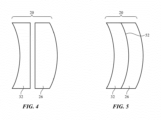
- FIG. 4 shows how lens elements 32 and 26 may, if desired, be separated by an air gap in system 20.
- Antireflection coatings may be provided on the planar surfaces of element 32 and/or 26 to reduce reflections, if desired.
- system 20 is formed from lens elements with additional curved surfaces.
- elements 32 and 26 are meniscus lenses and meet at curved mating surface 52.
- the optical systems of FIGS. 4 and 5 may include quarter wave plates, partially reflecting mirrors, and reflective polarizers to form catadioptric lenses as described in connection with catadioptric lens systems (lenses) 20 of FIGS. 2 and 3 .
- reflective polarizer 30 has been formed on the surface of additional lens element 54.
- Reflective polarizer 30 and lens element 54 may be attached to the adjacent curved surface of lens element 32 using optically clear adhesive (as an example).
- the surface of lens element 54 facing user 46 may have a curved surface.
- the thickness of lens element 54 may, if desired, be constant (e.g., the thickness of element 54 may vary by less than 10% or less than 5% or other suitable amount across its diameter).
- linear polarizer 34 may be formed on the curved surface of lens element 54 that faces user 46 to help suppress reflections of stray ambient light.
- Linear polarizer 34 may be oriented so that the pass axis of linear polarizer 34 is aligned with the X axis so that rays of image light such as light ray R7 of FIG. 2 will pass to user 46 for viewing while ambient light rays passing through polarizer 34 (in the -Z direction) will become X-polarized due to the X-axis pass axis orientation of linear polarizer 34 and will therefore not be reflected by reflective polarizer 30 (which has a reflective axis oriented with the Y axis). Obliquely oriented ambient light rays will also tend to be reflected away from user 46 due to the curved surfaces of the lens elements in system 20. The presence of linear polarizer 34 will therefore help to reduce stray light reflections toward user 46 from the inwardly facing side of system 20.
- Outwardly facing surface S4 of lens element 54 may be curved (e.g., convex) and opposing mating inwardly facing surface S5 of lens element 32 may be correspondingly curved (e.g., concave).
- surfaces S4 and S5 may be rotationally symmetric about the Z axis of FIG. 6 (e.g., lens elements 54 and 32 may be dome lenses and surfaces S4 and S5 may be dome lens surfaces). This allows lens element 54 to be rotated relative to lens element 32 (e.g., to align reflective polarizer 30 to quarter wave plate 28, etc.).
- surfaces S6 and S7 are planar. This helps avoid imposing undesired stresses on quarter wave plate 28 (which may, as an example, be formed from a birefringent stretched film).
- FIG. 7 Another illustrative arrangement for minimizing quarter wave plate stress is shown in FIG. 7 .
- surfaces S6 and S7 have a cylindrical curved shape (S6 is convex and S7 is concave so that these cylindrical shapes mate).
- quarter wave plate 28 of FIG. 7 is curved, quarter wave plate 28 is only bent (curved) about a single axis (the Y axis) and is not bent about the X axis.
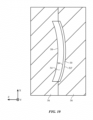
- FIGS. 8 and 9 show cross-sectional side views of lens elements 32 and 26 of FIG. 7 .
- FIG. 8 is a cross-sectional side view viewed along the Y axis.
- Quarter wave plate 28 is interposed between cylindrical surface S6 of lens element 32 and cylindrical surface S7 of lens element 26 and is bent about an axis parallel to the Y axis as shown in FIG. 8.
- FIG. 9 which is a cross-sectional side view of lens elements 32 and 26 of FIG. 7 viewed along the X axis, shows how surfaces S6 and S7 do not bend about the X axis. Because surfaces S6 and S7 have this cylindrical shape, quarter wave plate 28 does not exhibit compound curvature and is not exposed to undesired amounts of stress so that a relatively uniform retardance is provided by the quarter wave plate 28 across the lens assembly.
- FIG. 10 shows how lens elements such as lens element 54 may be formed by injection molding of plastic (polymer) or other material into mold 56.
- Reflective polarizer 30 may be placed in mold 56 so that the reflective surface of reflective polarizer 30 bears against mold surface S5' as plastic is injected into the interior cavity of mold 56 to form lens element 54.
- Mold surface S5' can be machined with high accuracy, so pressing reflective polarizer 30 against surface S5 ' during molding operations will help enhance the smoothness and accuracy of the reflective surface of reflective polarizer 30.
- reflective polarizer 30 can be formed by molding reflective polarizer 30 against opposing surface 58 during injection molding operations.
- the lens elements used in optical system 20 may be relatively thin and formed of light-weight materials (e.g., plastic) and/or may be formed from materials such as glass. Reductions in weight may help provide user 46 with a comfortable viewing experience. It may be easier to mold the lens element(s) with uniform optical properties including low birefringence when lens elements such as element 54 have a uniform thickness.
- quarter wave plate 28 may be interposed between lens elements 32 and 26 when elements 32 and 26 are bonded together (e.g., using adhesive layers on opposing sides of quarter wave plate 28).
- Surfaces S6 and S7 may be planar (e.g., element 32 may be a plano-concave element and element 26 may be a plano-convex element), as described in connection with FIG. 6 , or surfaces S6 and S7 may be curved (see, e.g., FIG. 7 ).
- surfaces S6 and S7 can be cylindrical surfaces (surfaces bent around one axis). In this type of configuration, quarter wave plate 28 may bend along only one axis (e.g., quarter wave plate 28 may not have any compound curves), thereby reducing distortion in quarter wave plate 28 and helping to ensure that the retardation provided by quarter wave plate 28 is uniform.
- a planar piece of quarter wave film may be placed between elements 32 and 26 with optical adhesive on either side of the quarter wave film. Elements 32 and 26 may then be forced together to distribute the adhesive and bend the quarter wave film about axis Y (an axis parallel to axis Y).
- Providing a cylindrically curved shape for surfaces S6 and S7 can enable the thickness of lens elements 32 and 26 to be reduced.
- the use of cylindrically curved shapes for surfaces S6 and S7 can help make for a more uniform thickness across the lens elements and thereby improve lens element moldability.
- uniformity of thickness in the mold cavity can help improve uniformity of flow of the molten plastic as it is being injected into the mold and the melt front flows across the mold cavity.
- the presence of a uniform flow during molding can be important for preventing flow lines in the molded lens, particularly when the lens element is thicker at the edge than the center. More uniform flow can also result in a lower birefringence in the molded lens elements.
- low birefringence in the lens elements helps to maintain control of the polarization state of the image light, so that stray light and ghosts are reduced and so user 46 is thereby provided with a high contrast image without stray light artifacts.
- quarter wave plate 28 may help ensure that light rays in system 20 pass through quarter wave plate 28 with an angle that is closer to normal incidence than with planar wave plate configurations.
- the retardation provided by quarter wave plate 28 may be more uniform across the lens element and the image provided to user 46 may as a result be more uniform in contrast with fewer ghost artifacts.
- image light is converted from unpolarized light to linearly polarized light, to circularly polarized light, then back to linearly polarized light, back to circularly polarized light and finally back to linearly polarized light.
- image light is converted from unpolarized light to linearly polarized light, to circularly polarized light, then back to linearly polarized light, back to circularly polarized light and finally back to linearly polarized light.
- quarter wave plates 28 and 18 may be accurately oriented relative to the polarization axis of the polarizers.
- the fast axis of the quarter wave plate 18 may be desirable to accurately orient the fast axis of the quarter wave plate 18 at 45 degrees to the polarization axis (pass axis) of linear polarizer 16 and the fast axis of quarter wave plate 28 at 45 degrees to the polarization axis (pass axis) of reflective polarizer 30.
- the fast axes of the quarter wave plates may, for example, be oriented at 45 degrees to the polarization axes of the respective polarizers within +/- 1.5 degrees or other suitable alignment tolerance.
- Accurate alignment of the quarter wave plates to the polarization axes of the polarizers helps ensure that light does not have a mixed polarization state (is not elliptically polarized). Accurate alignment therefore prevents portions of the image light from following unintended paths that form ghost images that degrade contrast and present stray light artifacts.
- Linear polarizer 16 and quarter wave plate 18 may be aligned during lamination. For example, rolls of polarizer film and quarter wave film can be accurately aligned to one another in a rewinding process and laminated together with optically clear adhesive so that the alignment is maintained. The laminated polarizer/quarter wave film can then be attached to a substrate for mounting into the optical system or attached directly to a cover glass or other structure associated with pixel array 14. Emissive displays such as organic light-emitting diode displays and light-emitting diode displays formed from arrays of crystalline semiconductor light-emitting diode dies may provide unpolarized image light so that attaching a laminated polarizer/quarter wave film to the pixel array allows the display system to emit circularly polarized light.
- Quarter wave plate 28 can also be accurately aligned with reflective polarizer 30.
- Reflective polarizer 30 can be formed in a curved shape (e.g., by thermoforming with heat and differential pressure or pressure forming), either directly to the concave surface of the lens element 32 or to a mold that matches the concave surface of the lens element 32 (e.g., mold 56 of FIG. 10 ). Either the quarter wave plate 28 or reflective polarizer 30 can then be aligned during an assembly process in which two lens elements 32 and 54 are bonded with reflective polarizer 30 and curved quarter wave plate 28.
- Either reflective polarizer 30 or the curved quarter wave plate 28 may, for example, be bonded to one of lens elements 32 or 54 and the remaining elements of system 20 may be oriented with a desired alignment accuracy.
- a polarimeter can be used to measure through optical system 20 during alignment to determine how much ellipticity is present and to use this information in guiding the alignment during assembly.
- the interface between lens elements 32 and 26 is planar.
- quarter wave plate 28 can be bonded to the planar side of plano-convex lens element 26 and reflective polarizer 30 can be bonded to the concave side of plano-concave lens element 32.
- Lens elements 32 and 26 can then be rotated relative to one another while polarization ellipticity is measured. Once it is determined that the quarter wave plate 28 is aligned satisfactorily to reflective polarizer 30, the components of optical system 20 can be bonded together to preserve alignment.
- dome optics may be used to facilitate alignment of polarizer 30 and quarter wave plate 28.
- convex surface may be used to facilitate alignment of polarizer 30 and quarter wave plate 28.
- linear polarizer 34 may be formed on the eye side (concave surface S8) of element 54 to help prevent spurious reflections of light from the environment.
- Linear polarizer 34 can be a separate layer, either flat or curved, positioned between optical system 20 and user's eye 46.
- Linear polarizer 34 can also be attached to surface S8 of lens element 54 (e.g., an inner dome lens surface) or can be laminated to reflective polarizer 30 before polarizer 30 is formed on surface S4 of lens element 54.
- Linear polarizer 34 may be aligned relative to reflective polarizer 30 so the pass axes of the two polarizers are aligned.
- linear polarizer 34 absorbs light from the environment that has the polarization state that would be reflected by reflective polarizer 30.
- Light from the environment that has the polarization state that is transmitted by both linear polarizer 34 and reflective polarizer 30 passes through quarter wave plate 28 and quarter wave plate 18 ending with a linear polarization state that is absorbed by linear polarizer 16.
- This helps reduce stray light reflections, because reflective polarizer 30 reflects light of this polarization state with a high reflectivity, which has the potential to create distracting reflections of light entering device 10 from behind or to the side of user 46.
- linear polarizer 34 is aligned so the transmission axis of the linear polarizer 34 is parallel to the transmission axis of reflective polarizer 30 and thereby helps enable linear polarizer 34 to serve as a cleanup polarizer to improve the quality of images from pixel array 14 while reducing the brightness of the image light presented to the eye of the user by a relatively small amount (e.g., ⁇ 20% if linear polarizer 34 has a transmission of 40% and ⁇ 10% if linear polarizer 34 has a transmission of 45%).
- Linear polarizer 34 may be a high transmission polarizer with a transmission of at least 40%, at least 43%, or at least 45% compared to unpolarized light.
- quarter wave plates in system 28 may be formed from multiple layers of retarder films laminated together.
- the layers of retarder films may be oriented at angles to one another so that together they act as a quarter wave plate with reduced variation in retardation as measured in waves over a broader spectral bandwidth, also known as an achromatic quarter wave.
- the retardation of quarter wave plates 18 and/or 28 may be within + / - 1.5° over a wavelength range of 450-650 nm).
- a primer e.g., an adhesion promoting polymer
- a primer may be applied to one or more surfaces of reflective polarizer 30 prior to insert molding of dome lens element 54. This may help increase the bond strength between reflective polarizer 30 and dome lens element 54 after molding.
- Reflective polarizer 30 may, if desired, have a substrate formed from a material such as polycarbonate or cyclic olefin that matches the thermal expansion of the lens elements in system 20 (e.g. acrylate or cyclic olefin lens elements), thereby reducing interfacial stress when optical system 20 is exposed to heat either from display system 40 or the environment.
- a material such as polycarbonate or cyclic olefin that matches the thermal expansion of the lens elements in system 20 (e.g. acrylate or cyclic olefin lens elements), thereby reducing interfacial stress when optical system 20 is exposed to heat either from display system 40 or the environment.
- lens element 26, which is interposed between the other lens elements of system 20 and display system 40 may be made from glass (which may have lower thermal expansion and higher heat resistance capabilities than plastic) to help resist heat effects from display system 20.
- a soft adhesive or an optical grease may be used to cement quarter wave plate 28 between lens elements 54 and 32 to enable some differential thermal expansion with reduced interfacial stress between the two lens elements and quarter wave plate 28.
- a head-mounted display configured to display images viewable by a user
- the head-mounted display includes an additional linear polarizer through which the light passes after passing through the reflective polarizer.
- the second planar quarter wave plate is formed at the planar surface of the plano-convex lens element.
- the head-mounted display includes a planoconcave lens element having a concave surface and an opposing planar surface, the planar surface of the plano-concave element is parallel to the planar surface of the plano-convex lens element.
- planar surface of the plano-convex lens element faces the planar surface of the plano-concave lens element.
- the reflective polarizer is formed at the concave surface of the plano-concave lens.
- the head-mounted includes an additional lens element, the reflective polarizer is interposed between the additional lens element and the plano-concave lens element.
- the head-mounted display includes an additional linear polarizer at a surface of the additional lens element, the additional lens element is interposed between the additional linear polarizer and the reflective polarizer.
- the head-mounted display includes control circuitry that is configured to supply image data to the array of pixels, and input-output devices coupled to the control circuitry.
- the input-output devices include a camera.
- ahead-mounted display configured to display images viewable by a user
- the head-mounted display includes an additional linear polarizer at the sixth surface through which the light passes after passing through the reflective polarizer.
- the first surface is a convex surface and the second surface is a planar surface.
- the third surface is a planar surface
- the fourth surface is a concave surface
- the fifth surface is a convex surface
- the sixth surface is a concave surface
- the second surface is a concave surface and the third surface is a convex surface.
- the first surface is a convex surface
- the second surface is a concave surface
- the third surface is a convex surface
- the second and third surfaces have cylindrical shapes.
- the fourth and fifth surfaces are dome-shaped surfaces.
- a head-mounted device configured to present images to a user
- the catadioptric system includes a first lens element having a first surface that is convex and having an opposing second surface, a partially reflecting mirror on the first surface, a quarter wave plate at the second surface, a second lens element having a having a third surface at the quarter wave plate and an opposing fourth surface that is concave, a reflective polarizer at the fourth surface having a reflection axis and having a pass axis that is perpendicular to the reflection axis, and a third lens element having a fifth surface that is convex at the reflective polarizer and an opposing sixth surface that is concave.
- the head-mounted device includes a linear polarizer on the sixth surface.
- the second and third surfaces are planar and the quarter wave plate is planar.
- the second and third surfaces have mating cylindrical shapes.
- the head-mounted display defined in embodiment 1 further comprising: control circuitry that is configured to supply image data to the array of input-output devices coupled to the control circuitry.
- a head-mounted display configured to display images viewable by a user, comprising:
- the head-mounted display defined in embodiment 11 further comprising an additional linear polarizer at the sixth surface through which the light passes after passing through the reflective polarizer.
- first surface is a convex surface
- second surface is a concave surface
- third surface is a convex surface
- second and third surfaces have cylindrical shapes.
- a head-mounted device configured to present images to a user, comprising:
Landscapes
- Physics & Mathematics (AREA)
- General Physics & Mathematics (AREA)
- Optics & Photonics (AREA)
- Engineering & Computer Science (AREA)
- Computer Hardware Design (AREA)
- Theoretical Computer Science (AREA)
- Polarising Elements (AREA)
Applications Claiming Priority (5)
| Application Number | Priority Date | Filing Date | Title |
|---|---|---|---|
| US201662370170P | 2016-08-02 | 2016-08-02 | |
| US201662383911P | 2016-09-06 | 2016-09-06 | |
| US15/434,623 US10203489B2 (en) | 2016-08-02 | 2017-02-16 | Optical system for head-mounted display |
| PCT/US2017/044247 WO2018026633A1 (en) | 2016-08-02 | 2017-07-27 | Optical system for head-mounted display |
| EP17749077.8A EP3479164B1 (de) | 2016-08-02 | 2017-07-27 | Optisches system für eine kopfmontierte anzeige |
Related Parent Applications (2)
| Application Number | Title | Priority Date | Filing Date |
|---|---|---|---|
| EP17749077.8A Division EP3479164B1 (de) | 2016-08-02 | 2017-07-27 | Optisches system für eine kopfmontierte anzeige |
| EP17749077.8A Division-Into EP3479164B1 (de) | 2016-08-02 | 2017-07-27 | Optisches system für eine kopfmontierte anzeige |
Publications (3)
| Publication Number | Publication Date |
|---|---|
| EP4318080A2 true EP4318080A2 (de) | 2024-02-07 |
| EP4318080A3 EP4318080A3 (de) | 2024-04-10 |
| EP4318080B1 EP4318080B1 (de) | 2025-12-24 |
Family
ID=61071438
Family Applications (2)
| Application Number | Title | Priority Date | Filing Date |
|---|---|---|---|
| EP23216531.6A Active EP4318080B1 (de) | 2016-08-02 | 2017-07-27 | Optisches system für eine kopfmontierte anzeige |
| EP17749077.8A Active EP3479164B1 (de) | 2016-08-02 | 2017-07-27 | Optisches system für eine kopfmontierte anzeige |
Family Applications After (1)
| Application Number | Title | Priority Date | Filing Date |
|---|---|---|---|
| EP17749077.8A Active EP3479164B1 (de) | 2016-08-02 | 2017-07-27 | Optisches system für eine kopfmontierte anzeige |
Country Status (6)
| Country | Link |
|---|---|
| US (6) | US10203489B2 (de) |
| EP (2) | EP4318080B1 (de) |
| JP (1) | JP6687805B2 (de) |
| KR (1) | KR102185156B1 (de) |
| AU (1) | AU2017307221B2 (de) |
| WO (1) | WO2018026633A1 (de) |
Families Citing this family (151)
| Publication number | Priority date | Publication date | Assignee | Title |
|---|---|---|---|---|
| US10203489B2 (en) | 2016-08-02 | 2019-02-12 | Apple Inc. | Optical system for head-mounted display |
| KR102723417B1 (ko) * | 2016-12-26 | 2024-10-28 | 엘지디스플레이 주식회사 | 헤드 장착형 디스플레이 |
| CN106932904A (zh) * | 2017-02-27 | 2017-07-07 | 阿里巴巴集团控股有限公司 | 虚拟现实头戴设备 |
| US11543669B2 (en) | 2017-03-08 | 2023-01-03 | Meta Platforms Technologies, Llc | Wide angle variable neutral density filter |
| WO2018211405A2 (en) * | 2017-05-16 | 2018-11-22 | 3M Innovative Properties Company | Optical system |
| EP3642666A4 (de) | 2017-07-17 | 2021-04-14 | Gary Sharp Innovations, LLC | Weitwinkelkompensation von einachsigen retarderstapeln |
| US12013559B2 (en) * | 2017-10-09 | 2024-06-18 | 3M Innovative Properties Company | Optical components and optical systems |
| CN107589546B (zh) * | 2017-10-23 | 2024-05-24 | 北京小米移动软件有限公司 | 光学系统及增强现实眼镜 |
| US11054622B1 (en) * | 2017-11-20 | 2021-07-06 | Facebook Technologies, Llc | Folded viewing optics with an optical retarder on a simple surface |
| CN107797325A (zh) * | 2017-11-22 | 2018-03-13 | 维沃移动通信有限公司 | 一种柔性液晶屏模组以及一种柔性液晶屏模组的组装方法 |
| JP2019101181A (ja) * | 2017-11-30 | 2019-06-24 | キヤノン株式会社 | 撮像装置 |
| CN107861247B (zh) * | 2017-12-22 | 2020-08-25 | 联想(北京)有限公司 | 光学部件及增强现实设备 |
| CN112219140A (zh) | 2018-01-29 | 2021-01-12 | 加里夏普创新有限责任公司 | 中空三通光学元件 |
| US11249355B2 (en) | 2018-01-29 | 2022-02-15 | Gary Sharp Innovations, Llc | Color switch for reduced color cross-talk |
| CN115685432A (zh) | 2018-03-02 | 2023-02-03 | 加里夏普创新有限责任公司 | 用于偏振基向量转换的延迟器堆栈对 |
| US11243397B2 (en) * | 2018-05-18 | 2022-02-08 | Facebook Technologies, Llc | Optical assembly with polarization volume holographic element |
| US10670861B2 (en) * | 2018-06-04 | 2020-06-02 | Facebook Technologies, Llc | Optical assembly with waveplate configuration for ghost image reduction |
| US11226483B2 (en) | 2018-06-07 | 2022-01-18 | Facebook Technologies, Llc | Reverse-order crossed pancake lens with a shaped polarizer |
| US11378811B2 (en) * | 2018-06-18 | 2022-07-05 | Facebook Technologies, Llc | Optical assembly with curved reflective polarizer for head mounted display |
| CN110161692A (zh) * | 2018-07-16 | 2019-08-23 | 上海视涯信息科技有限公司 | 一种虚拟现实显示装置 |
| US10778963B2 (en) * | 2018-08-10 | 2020-09-15 | Valve Corporation | Head-mounted display (HMD) with spatially-varying retarder optics |
| US11022784B1 (en) | 2018-08-17 | 2021-06-01 | Facebook Technologies, Llc | Use of folded optics to reduce volume in a virtual-reality system |
| US11885959B1 (en) | 2018-08-31 | 2024-01-30 | Apple Inc. | Optical system with ghost image mitigation |
| CN111694157B (zh) | 2018-08-31 | 2025-07-04 | 华为技术有限公司 | 一种光学成像系统 |
| US11237413B1 (en) | 2018-09-10 | 2022-02-01 | Apple Inc. | Multi-focal display based on polarization switches and geometric phase lenses |
| US10852553B2 (en) * | 2018-09-21 | 2020-12-01 | Apple Inc. | Electronic device with a tunable lens |
| US11086161B2 (en) * | 2018-09-26 | 2021-08-10 | Facebook Technologies, Llc | Active alignment of pancake lens based display assemblies |
| WO2020072635A1 (en) * | 2018-10-02 | 2020-04-09 | Gary Sharp Innovations, Llc | Polarization folded path device with complementary angle filtering |
| US11372239B1 (en) | 2018-11-01 | 2022-06-28 | Facebook Technologies, Llc | Enabling eye tracking in pancake lens optics |
| KR102706916B1 (ko) * | 2019-01-02 | 2024-09-20 | 삼성디스플레이 주식회사 | 증강 현실 제공 장치 |
| CN109709675B (zh) * | 2019-02-26 | 2021-11-19 | 京东方科技集团股份有限公司 | 增强现实显示设备和增强现实眼镜 |
| CN109765691B (zh) * | 2019-03-08 | 2023-09-01 | 歌尔光学科技有限公司 | 一种光学系统及显示设备 |
| US11169354B2 (en) * | 2019-03-15 | 2021-11-09 | Facebook Technologies, Llc | System and method for automatic lens assembling and testing |
| US11156755B2 (en) * | 2019-03-28 | 2021-10-26 | Facebook Technologies, Llc | Aligning a polarization device using a spatially variant polarization element |
| US11366260B1 (en) * | 2019-05-20 | 2022-06-21 | Facebook Technologies, Llc | Optical system with polarization volume hologram |
| CN110208951A (zh) * | 2019-07-19 | 2019-09-06 | 业成科技(成都)有限公司 | 头戴虚拟现实显示装置之薄轻光学系统 |
| CN110426853B (zh) | 2019-07-31 | 2020-10-16 | 华为技术有限公司 | 镜片和头戴式显示装置 |
| CN114467049B (zh) * | 2019-08-15 | 2024-08-30 | 奇跃公司 | 具有像素阵列的透视显示器中的重影图像减轻 |
| US11327316B2 (en) * | 2019-08-20 | 2022-05-10 | Apple Inc. | Particle control for head-mount able device |
| US11822081B2 (en) * | 2019-08-29 | 2023-11-21 | Apple Inc. | Optical module for head-mounted device |
| US11885965B1 (en) | 2019-09-23 | 2024-01-30 | Apple Inc. | Head-mounted display and display modules thereof |
| WO2021102148A1 (en) * | 2019-11-22 | 2021-05-27 | Valve Corporation | Head-mounted display (hmd) with spatially-varying retarder optics |
| CN111025659B (zh) * | 2019-12-31 | 2022-04-19 | 合肥视涯技术有限公司 | 一种增强现实光学模组及增强现实设备 |
| CN118068574A (zh) | 2020-01-15 | 2024-05-24 | 富士胶片株式会社 | 光学系统 |
| US11209657B2 (en) | 2020-01-24 | 2021-12-28 | Valve Corporation | Position tracking system for head-mounted display systems that includes angle sensitive detectors |
| US11073906B1 (en) | 2020-01-27 | 2021-07-27 | Valve Corporation | Eye tracking system for head-mounted display devices |
| US11243399B2 (en) | 2020-01-31 | 2022-02-08 | Microsoft Technology Licensing, Llc | Head mounted display device with double faceted optics |
| US11435503B2 (en) * | 2020-01-31 | 2022-09-06 | Microsoft Technology Licensing, Llc | Head mounted display device with double faceted optics |
| US11320692B2 (en) | 2020-02-03 | 2022-05-03 | Valve Corporation | Spatially varying polarizer for display backlight |
| JP7708516B2 (ja) * | 2020-02-06 | 2025-07-15 | バルブ コーポレーション | ヘッドマウントディスプレイシステムのワイヤグリッド偏光子向け偏光補償 |
| CN114787672A (zh) | 2020-02-06 | 2022-07-22 | 威尔乌集团 | 用于显示系统的校正偏振补偿光学部件 |
| KR20220136422A (ko) | 2020-02-06 | 2022-10-07 | 밸브 코포레이션 | 공간적으로 변화하는 편광기들을 사용하는 시야 기반 광학 교정 |
| WO2021158971A1 (en) | 2020-02-06 | 2021-08-12 | Valve Corporation | Micro-lens array polarization recycling optic for illumination optics |
| WO2021158804A1 (en) | 2020-02-06 | 2021-08-12 | Valve Corporation | Position tracking system for head-mounted display systems |
| WO2021158554A1 (en) | 2020-02-06 | 2021-08-12 | Valve Corporation | Polarization-multiplexed optics for head-mounted display systems |
| KR20220131341A (ko) | 2020-02-06 | 2022-09-27 | 밸브 코포레이션 | 스캔 빔 시스템들에 대한 공간적으로 및 시간 변화하는 편광 교정 광학부 |
| US11526036B2 (en) | 2020-02-06 | 2022-12-13 | Valve Corporation | Variable optical correction using spatially varying polarizers |
| WO2021162781A1 (en) | 2020-02-11 | 2021-08-19 | Valve Corporation | Polarimetry camera for high fidelity surface characterization measurements |
| WO2021162989A1 (en) | 2020-02-11 | 2021-08-19 | Valve Corporation | Camera device employing spatially varying polarizers |
| JP7679940B2 (ja) | 2020-02-11 | 2025-05-20 | バルブ コーポレーション | 照明オプティクスのための回折素子の偏光ベース多重化 |
| WO2021174220A1 (en) * | 2020-02-29 | 2021-09-02 | Gary Sharp Innovations, Llc | Preserving in-plane function of polarization laminates in a forming process |
| US11719936B2 (en) * | 2020-03-23 | 2023-08-08 | Apple Inc. | Optical system for head-mounted display |
| US11366311B2 (en) | 2020-04-01 | 2022-06-21 | Panasonic Intellectual Property Management Co., Ltd. | Display device |
| JP7427077B2 (ja) | 2020-04-01 | 2024-02-02 | 富士フイルム株式会社 | 光学素子、画像表示ユニットおよびヘッドマウントディスプレイ |
| WO2021246286A1 (ja) * | 2020-06-01 | 2021-12-09 | 富士フイルム株式会社 | 光学要素、画像表示装置、仮想現実表示装置、電子ファインダー、偏光子の製造方法 |
| US11656500B2 (en) * | 2020-06-10 | 2023-05-23 | Meta Platforms Technologies, Llc | Switchable multilayer cholesteric liquid crystal reflective polarizer |
| CN115698822A (zh) * | 2020-06-30 | 2023-02-03 | 谷歌有限责任公司 | 自由形式偏振光导 |
| US11906736B1 (en) | 2020-08-03 | 2024-02-20 | Raytrx, Llc | Wearable pupil-forming display apparatus |
| US11353711B1 (en) | 2020-08-03 | 2022-06-07 | Raytrx, Llc | Wearable pupil-forming display apparatus |
| US12681281B2 (en) * | 2020-09-11 | 2026-07-14 | 3M Innovative Properties Company | Catadioptric lens assembly having two or more lens components |
| TWI736431B (zh) * | 2020-09-25 | 2021-08-11 | 宏碁股份有限公司 | 頭戴式顯示裝置 |
| WO2022075264A1 (ja) * | 2020-10-09 | 2022-04-14 | 富士フイルム株式会社 | ヘッドマウントディスプレイ用光学系の製造方法 |
| CN112198665B (zh) * | 2020-10-27 | 2022-10-18 | 北京耐德佳显示技术有限公司 | 一种阵列波导近眼显示装置 |
| CN112596240B (zh) * | 2020-12-21 | 2022-09-20 | 歌尔光学科技有限公司 | 成像光路和头戴显示设备 |
| CN112666708B (zh) * | 2020-12-24 | 2023-06-27 | 业成科技(成都)有限公司 | 复合式光学装置及其制造方法 |
| CN114690415A (zh) * | 2020-12-29 | 2022-07-01 | 华为技术有限公司 | 光学模组及电子设备 |
| WO2022164625A1 (en) * | 2021-02-01 | 2022-08-04 | Perdix Systems Llc | Wave plate arrangements for an optical system |
| JP7696108B2 (ja) | 2021-02-26 | 2025-06-20 | パナソニックIpマネジメント株式会社 | 接眼光学系および表示装置 |
| TWI858237B (zh) | 2021-03-05 | 2024-10-11 | 大立光電股份有限公司 | 頭戴裝置 |
| GB2604894B (en) * | 2021-03-17 | 2023-04-26 | Trulife Optics Ltd | Encapsulation of thin films within eyeglass lenses |
| WO2022229749A1 (en) * | 2021-04-29 | 2022-11-03 | 3M Innovative Properties Company | Optical system |
| CN117242387A (zh) * | 2021-04-29 | 2023-12-15 | 元平台技术有限公司 | 高效率薄饼透镜 |
| US11493773B2 (en) | 2021-06-07 | 2022-11-08 | Panamorph, Inc. | Near-eye display system |
| US12204096B2 (en) | 2021-06-07 | 2025-01-21 | Panamorph, Inc. | Near-eye display system |
| WO2022266181A1 (en) * | 2021-06-15 | 2022-12-22 | Meta Platforms Technologies, Llc | Dual-reflector optical component |
| JP7514588B2 (ja) * | 2021-06-30 | 2024-07-11 | パナソニックオートモーティブシステムズ株式会社 | 表示装置 |
| CN117581148A (zh) * | 2021-07-02 | 2024-02-20 | 苹果公司 | 具有透镜模块的电子设备 |
| TWM621801U (zh) | 2021-08-16 | 2022-01-01 | 大立光電股份有限公司 | 頭戴裝置 |
| US20230093721A1 (en) * | 2021-09-23 | 2023-03-23 | Valve Corporation | Head-mounted display system with compact optics |
| JP7731752B2 (ja) * | 2021-09-30 | 2025-09-01 | キヤノン株式会社 | 接眼光学系及び画像表示装置 |
| CN116027551A (zh) * | 2021-10-26 | 2023-04-28 | 广州视源电子科技股份有限公司 | 一种短焦折叠光学系统以及虚拟现实显示设备 |
| EP4399564A1 (de) * | 2021-11-01 | 2024-07-17 | Apple Inc. | Linsenmodul mit zwei durch einen luftspalt getrennten linsenelementen |
| TWM623420U (zh) | 2021-11-10 | 2022-02-11 | 大立光電股份有限公司 | 光學系統與頭戴裝置 |
| WO2023091322A1 (en) * | 2021-11-16 | 2023-05-25 | Kokanee Research Llc | Tunable lens controlled by an actuator |
| CN114236865A (zh) * | 2021-11-23 | 2022-03-25 | 青岛歌尔声学科技有限公司 | 光学模组及头戴显示设备 |
| CN118541628A (zh) * | 2022-01-18 | 2024-08-23 | 3M创新有限公司 | 光学膜和包括光学膜的光学透镜 |
| CN118575116A (zh) * | 2022-01-21 | 2024-08-30 | 威尔乌集团 | 用于头戴式显示系统的紧凑型光学器件 |
| GB2616020B (en) * | 2022-02-23 | 2024-08-14 | Spectralics Ltd | An efficient ghost-less reflector exploiting P-polarization |
| WO2023176655A1 (ja) * | 2022-03-14 | 2023-09-21 | 日東電工株式会社 | レンズ部および積層フィルム |
| JP2024095087A (ja) * | 2022-12-28 | 2024-07-10 | 日東電工株式会社 | 表示システムおよび積層フィルム |
| JP7898375B2 (ja) * | 2022-12-28 | 2026-07-31 | 日東電工株式会社 | 表示システムおよび積層フィルム |
| WO2023176658A1 (ja) * | 2022-03-14 | 2023-09-21 | 日東電工株式会社 | レンズ部および積層フィルム |
| JP2024095147A (ja) * | 2022-12-28 | 2024-07-10 | 日東電工株式会社 | 表示システム、表示方法、表示体および表示体の製造方法 |
| JP2024095082A (ja) * | 2022-12-28 | 2024-07-10 | 日東電工株式会社 | レンズ部および積層フィルム |
| KR20240157671A (ko) * | 2022-03-14 | 2024-11-01 | 닛토덴코 가부시키가이샤 | 표시 시스템 및 적층 필름 |
| JP2024122667A (ja) * | 2023-02-28 | 2024-09-09 | 日東電工株式会社 | 表示システム、表示方法、表示体および表示体の製造方法 |
| KR20240154570A (ko) * | 2022-03-14 | 2024-10-25 | 닛토덴코 가부시키가이샤 | 표시 시스템 및 적층 필름 |
| JP7898374B2 (ja) * | 2022-12-28 | 2026-07-31 | 日東電工株式会社 | 表示システムおよび積層フィルム |
| WO2023176628A1 (ja) * | 2022-03-14 | 2023-09-21 | 日東電工株式会社 | 光学積層体および表示システム |
| JP2024095148A (ja) * | 2022-12-28 | 2024-07-10 | 日東電工株式会社 | 表示システム、表示方法、表示体および表示体の製造方法 |
| JP2024095086A (ja) * | 2022-12-28 | 2024-07-10 | 日東電工株式会社 | 表示システムおよび積層フィルム |
| KR20240156381A (ko) * | 2022-03-14 | 2024-10-29 | 닛토덴코 가부시키가이샤 | 표시 시스템, 표시 방법, 표시체 및 표시체의 제조 방법 |
| WO2023176656A1 (ja) * | 2022-03-14 | 2023-09-21 | 日東電工株式会社 | レンズ部および積層フィルム |
| JP2024095149A (ja) * | 2022-12-28 | 2024-07-10 | 日東電工株式会社 | 光学積層体および表示システム |
| WO2023176626A1 (ja) * | 2022-03-14 | 2023-09-21 | 日東電工株式会社 | 表示システム、表示方法、表示体および表示体の製造方法 |
| WO2023176692A1 (ja) * | 2022-03-14 | 2023-09-21 | 日東電工株式会社 | 表示システム、表示方法、表示体および表示体の製造方法 |
| JP2024122666A (ja) * | 2023-02-28 | 2024-09-09 | 日東電工株式会社 | 表示システム、表示方法、表示体および表示体の製造方法 |
| EP4495670A4 (de) * | 2022-03-14 | 2026-03-18 | Nitto Denko Corp | Anzeigesystem und laminierter film |
| JP7547456B2 (ja) * | 2022-12-28 | 2024-09-09 | 日東電工株式会社 | レンズ部、表示体および表示方法 |
| KR20240161120A (ko) * | 2022-03-14 | 2024-11-12 | 닛토덴코 가부시키가이샤 | 렌즈부 및 적층 필름 |
| KR20240155226A (ko) * | 2022-03-14 | 2024-10-28 | 닛토덴코 가부시키가이샤 | 표시 시스템, 표시 방법, 표시체 및 표시체의 제조 방법 |
| JP7880810B2 (ja) * | 2022-12-28 | 2026-06-26 | 日東電工株式会社 | レンズ部および積層フィルム |
| KR20240154571A (ko) * | 2022-03-14 | 2024-10-25 | 닛토덴코 가부시키가이샤 | 표시 시스템 및 적층 필름 |
| US20250189809A1 (en) * | 2022-03-14 | 2025-06-12 | Nitto Denko Corporation | Display system, display method, display body, and method for manufacturing display body |
| US12591147B1 (en) * | 2022-04-08 | 2026-03-31 | Meta Platforms Technologies, Llc | Curved surface lamination |
| JP2023159715A (ja) | 2022-04-20 | 2023-11-01 | シャープディスプレイテクノロジー株式会社 | 表示装置及びヘッドマウントディスプレイ |
| CN114706226B (zh) * | 2022-04-29 | 2023-12-12 | 业成科技(成都)有限公司 | 虚拟现实显示系统及头戴式显示设备 |
| TWI844025B (zh) | 2022-05-27 | 2024-06-01 | 大立光電股份有限公司 | 光學系統與頭戴裝置 |
| CN114967214B (zh) * | 2022-05-30 | 2023-10-27 | 京东方科技集团股份有限公司 | 显示装置和显示装置的控制方法 |
| CN119546998A (zh) * | 2022-07-04 | 2025-02-28 | 三星电子株式会社 | 包括透镜组件的可穿戴电子设备 |
| US12650546B2 (en) | 2022-08-02 | 2026-06-09 | Apple Inc. | Lens assembly including wave plate |
| TWI913504B (zh) | 2022-08-19 | 2026-02-01 | 大根光學工業股份有限公司 | 光學系統與頭戴裝置 |
| US12607868B2 (en) * | 2022-09-07 | 2026-04-21 | Apple Inc. | Catadioptric lens module |
| US20240111157A1 (en) * | 2022-09-29 | 2024-04-04 | Meta Platforms Technologies, Llc | Methods of manufacture for pancake optics |
| CN118050896A (zh) | 2022-11-17 | 2024-05-17 | 中强光电股份有限公司 | 光学镜头模块、光机模块以及头戴式显示装置 |
| TWI829434B (zh) * | 2022-11-17 | 2024-01-11 | 中強光電股份有限公司 | 光學鏡頭模組、光機模組以及頭戴式顯示裝置 |
| CN116224578B (zh) * | 2023-01-18 | 2025-09-16 | 业桓科技(成都)有限公司 | 显示系统及其消色散透镜组合 |
| JP7902764B2 (ja) * | 2023-02-16 | 2026-08-10 | 日東電工株式会社 | 表示システムの製造方法および光学フィルム群 |
| US20240361497A1 (en) * | 2023-04-28 | 2024-10-31 | Meta Platforms Technologies, Llc | Hybrid lens and casting method |
| US20240369835A1 (en) * | 2023-05-04 | 2024-11-07 | Tencent America LLC | Reflective polarizer including a fresnel optical element for near eye display |
| EP4682617A4 (de) * | 2023-06-28 | 2026-06-24 | Samsung Electronics Co Ltd | Tragbare elektronische vorrichtung mit linsenanordnung |
| CN116736492B (zh) * | 2023-08-09 | 2023-12-05 | 江西联昊光电有限公司 | 光学系统及光学设备 |
| JP2025037611A (ja) * | 2023-09-06 | 2025-03-18 | 日東電工株式会社 | 光学積層体の管理方法および表示システムの製造方法 |
| WO2025057648A1 (ja) * | 2023-09-14 | 2025-03-20 | 日東電工株式会社 | 光学積層体および表示システム |
| KR20260061183A (ko) * | 2023-09-14 | 2026-05-06 | 닛토덴코 가부시키가이샤 | 광학 적층체 및 표시 시스템 |
| US20250208403A1 (en) * | 2023-12-22 | 2025-06-26 | Genius Electronic Optical Co., Ltd. | Ocular optical system and mass production manufacturing method thereof |
| WO2025159289A1 (ko) * | 2024-01-23 | 2025-07-31 | 삼성전자주식회사 | 제1 렌즈 어셈블리 및 제2 렌즈 어셈블리를 포함하는 웨어러블 전자 장치 |
| JP2026013157A (ja) * | 2024-07-16 | 2026-01-28 | キヤノン株式会社 | 光学素子、光学系、光学機器、表示装置及び撮像装置 |
| JP7799763B1 (ja) | 2024-07-22 | 2026-01-15 | キヤノン株式会社 | 光学系および表示装置 |
| GB2643950A (en) | 2024-09-10 | 2026-03-11 | Trulife Optics Ltd | Optical eye tracking system |
| JP2026052795A (ja) * | 2024-09-12 | 2026-03-25 | 株式会社ジャパンディスプレイ | 表示装置およびヘッドアップディスプレイ |
Family Cites Families (35)
| Publication number | Priority date | Publication date | Assignee | Title |
|---|---|---|---|---|
| US3947760A (en) | 1973-11-14 | 1976-03-30 | Hewlett-Packard Company | Integrating component measuring device |
| US5303085A (en) | 1992-02-07 | 1994-04-12 | Rallison Richard D | Optically corrected helmet mounted display |
| US5357372A (en) | 1992-04-07 | 1994-10-18 | Hughes Aircraft Company | Ultra-compact, wide field of view virtual image display optical system |
| JPH07261088A (ja) | 1994-03-18 | 1995-10-13 | Olympus Optical Co Ltd | 共心光学系 |
| US7262919B1 (en) | 1994-06-13 | 2007-08-28 | Canon Kabushiki Kaisha | Head-up display device with curved optical surface having total reflection |
| JP3295583B2 (ja) | 1994-12-19 | 2002-06-24 | シャープ株式会社 | 光学装置および該光学装置を用いた頭部搭載型ディスプレイ |
| JPH08223509A (ja) * | 1995-02-14 | 1996-08-30 | Olympus Optical Co Ltd | 頭部装着型映像表示装置 |
| US5715023A (en) * | 1996-04-30 | 1998-02-03 | Kaiser Electro-Optics, Inc. | Plane parallel optical collimating device employing a cholesteric liquid crystal |
| US6204974B1 (en) * | 1996-10-08 | 2001-03-20 | The Microoptical Corporation | Compact image display system for eyeglasses or other head-borne frames |
| US6271969B1 (en) | 1998-12-11 | 2001-08-07 | Agilent Technolgoies, Inc. | Folded optical system having improved image isolation |
| US6075651A (en) * | 1999-01-28 | 2000-06-13 | Kaiser Electro-Optics, Inc. | Compact collimating apparatus |
| JP2000249984A (ja) * | 1999-02-26 | 2000-09-14 | Minolta Co Ltd | 反射透過偏光子を用いた光学系 |
| EP1110118A1 (de) * | 1999-07-02 | 2001-06-27 | Koninklijke Philips Electronics N.V. | Am kopf montierte anzeige |
| JP2001042257A (ja) * | 1999-07-30 | 2001-02-16 | Yaku Tsutsumi | 視野闘争の少ない立体画像表示装置 |
| US6400493B1 (en) | 1999-10-26 | 2002-06-04 | Agilent Technologies, Inc. | Folded optical system adapted for head-mounted displays |
| JP2002131693A (ja) * | 2000-10-26 | 2002-05-09 | Mixed Reality Systems Laboratory Inc | 画像観察装置 |
| US6853491B1 (en) | 2003-11-26 | 2005-02-08 | Frank Ruhle | Collimating optical member for real world simulation |
| EP1892543A1 (de) | 2006-08-23 | 2008-02-27 | JDS Uniphase Corporation | Kartesische Polarisatoren mit lichtausgerichteten Flüssigkristallen |
| US8488246B2 (en) | 2010-02-28 | 2013-07-16 | Osterhout Group, Inc. | See-through near-eye display glasses including a curved polarizing film in the image source, a partially reflective, partially transmitting optical element and an optically flat film |
| AU2011220382A1 (en) | 2010-02-28 | 2012-10-18 | Microsoft Corporation | Local advertising content on an interactive head-mounted eyepiece |
| US8983038B1 (en) | 2011-04-19 | 2015-03-17 | West Corporation | Method and apparatus of processing caller responses |
| WO2013033608A2 (en) | 2011-09-01 | 2013-03-07 | Wil Mccarthy | Thermotropic optical shutter incorporating coatable polarizers |
| TWI534475B (zh) | 2012-12-21 | 2016-05-21 | 財團法人工業技術研究院 | 虛像顯示裝置 |
| US9977246B2 (en) | 2014-03-18 | 2018-05-22 | 3M Innovative Properties Company | Low profile image combiner for near-eye displays |
| WO2015151004A1 (en) | 2014-03-31 | 2015-10-08 | Crt Technology, Inc. | Additive manufacturing of molds and methods of making molds and devices therefrom |
| JP6368579B2 (ja) | 2014-08-05 | 2018-08-01 | 株式会社日立エルジーデータストレージ | 映像投射装置及びこれを用いたヘッドマウントディスプレイ |
| US10139627B2 (en) | 2014-08-13 | 2018-11-27 | 3M Innovative Properties Company | Head-mounted display system and components |
| TWI551887B (zh) * | 2014-11-26 | 2016-10-01 | 中強光電股份有限公司 | 虛像顯示裝置 |
| JP6457636B2 (ja) * | 2015-09-03 | 2019-01-23 | スリーエム イノベイティブ プロパティズ カンパニー | 光学積層体及び光学システム |
| US9897778B2 (en) * | 2016-01-12 | 2018-02-20 | Omnivision Technologies, Inc. | Four-surface narrow field-of-view compound lens |
| US11054648B2 (en) | 2016-02-04 | 2021-07-06 | Google Llc | Compact near-eye display optics for higher optical performance |
| WO2017213912A2 (en) | 2016-06-09 | 2017-12-14 | 3M Innovative Properties Company | Optical system |
| US10203489B2 (en) | 2016-08-02 | 2019-02-12 | Apple Inc. | Optical system for head-mounted display |
| US11119321B2 (en) | 2018-09-10 | 2021-09-14 | Apple Inc. | Electronic device with a display attached to a lens element |
| US11467535B2 (en) | 2019-05-08 | 2022-10-11 | Samsung Electronics Co., Ltd. | Multi-image display apparatus providing holographic image |
-
2017
- 2017-02-16 US US15/434,623 patent/US10203489B2/en active Active
- 2017-07-27 KR KR1020197003157A patent/KR102185156B1/ko active Active
- 2017-07-27 EP EP23216531.6A patent/EP4318080B1/de active Active
- 2017-07-27 AU AU2017307221A patent/AU2017307221B2/en active Active
- 2017-07-27 WO PCT/US2017/044247 patent/WO2018026633A1/en not_active Ceased
- 2017-07-27 EP EP17749077.8A patent/EP3479164B1/de active Active
- 2017-07-27 JP JP2019505194A patent/JP6687805B2/ja active Active
-
2018
- 2018-12-18 US US16/224,561 patent/US10591707B2/en active Active
-
2020
- 2020-01-30 US US16/776,750 patent/US10928613B2/en active Active
-
2021
- 2021-01-15 US US17/150,919 patent/US11740446B2/en active Active
-
2023
- 2023-06-26 US US18/341,562 patent/US12140741B2/en active Active
-
2024
- 2024-10-02 US US18/905,011 patent/US20250028158A1/en active Pending
Also Published As
| Publication number | Publication date |
|---|---|
| US20200166738A1 (en) | 2020-05-28 |
| WO2018026633A1 (en) | 2018-02-08 |
| EP4318080B1 (de) | 2025-12-24 |
| US10591707B2 (en) | 2020-03-17 |
| EP3479164A1 (de) | 2019-05-08 |
| KR20190020826A (ko) | 2019-03-04 |
| EP4318080A3 (de) | 2024-04-10 |
| US10203489B2 (en) | 2019-02-12 |
| US20210132349A1 (en) | 2021-05-06 |
| AU2017307221A1 (en) | 2019-01-24 |
| US20190146198A1 (en) | 2019-05-16 |
| KR102185156B1 (ko) | 2020-12-01 |
| AU2017307221B2 (en) | 2019-08-29 |
| US12140741B2 (en) | 2024-11-12 |
| US20230333359A1 (en) | 2023-10-19 |
| US10928613B2 (en) | 2021-02-23 |
| EP3479164B1 (de) | 2024-05-08 |
| JP6687805B2 (ja) | 2020-04-28 |
| US20250028158A1 (en) | 2025-01-23 |
| US20180039052A1 (en) | 2018-02-08 |
| US11740446B2 (en) | 2023-08-29 |
| JP2019526075A (ja) | 2019-09-12 |
Similar Documents
| Publication | Publication Date | Title |
|---|---|---|
| US12140741B2 (en) | Optical system for head-mounted display | |
| CN110268301B (zh) | 用于头戴式显示器的光学系统 | |
| US11378811B2 (en) | Optical assembly with curved reflective polarizer for head mounted display | |
| US10901222B2 (en) | Optical system | |
| US20240111169A1 (en) | Electronic Device with a Lens Module | |
| US20240094455A1 (en) | Wave Plate Arrangements for an Optical System | |
| US20240264425A1 (en) | Lens Module Including Two Lens Elements Separated by an Air Gap | |
| US20240045128A1 (en) | Lens Assembly Including Wave Plate | |
| US12607868B2 (en) | Catadioptric lens module | |
| US20250028157A1 (en) | Strain-Insensitive Wave Plate Arrangements |
Legal Events
| Date | Code | Title | Description |
|---|---|---|---|
| PUAI | Public reference made under article 153(3) epc to a published international application that has entered the european phase |
Free format text: ORIGINAL CODE: 0009012 |
|
| STAA | Information on the status of an ep patent application or granted ep patent |
Free format text: STATUS: REQUEST FOR EXAMINATION WAS MADE |
|
| 17P | Request for examination filed |
Effective date: 20231214 |
|
| AC | Divisional application: reference to earlier application |
Ref document number: 3479164 Country of ref document: EP Kind code of ref document: P |
|
| AK | Designated contracting states |
Kind code of ref document: A2 Designated state(s): AL AT BE BG CH CY CZ DE DK EE ES FI FR GB GR HR HU IE IS IT LI LT LU LV MC MK MT NL NO PL PT RO RS SE SI SK SM TR |
|
| RIN1 | Information on inventor provided before grant (corrected) |
Inventor name: BORDEN JOHN N. Inventor name: CHENG WEIBO Inventor name: ANDERSON TYLER Inventor name: BOLLMANN BEN J. Inventor name: MYHRE GRAHAM B. Inventor name: ZHU NAN Inventor name: KHAN SAJJAD A. |
|
| REG | Reference to a national code |
Free format text: PREVIOUS MAIN CLASS: G02B0027010000 Ref country code: DE Ref legal event code: R079 Ref document number: 602017093323 Country of ref document: DE Ipc: G02B0027280000 |
|
| PUAL | Search report despatched |
Free format text: ORIGINAL CODE: 0009013 |
|
| AK | Designated contracting states |
Kind code of ref document: A3 Designated state(s): AL AT BE BG CH CY CZ DE DK EE ES FI FR GB GR HR HU IE IS IT LI LT LU LV MC MK MT NL NO PL PT RO RS SE SI SK SM TR |
|
| RIC1 | Information provided on ipc code assigned before grant |
Ipc: G02B 27/01 20060101ALI20240305BHEP Ipc: G02B 27/28 20060101AFI20240305BHEP |
|
| GRAP | Despatch of communication of intention to grant a patent |
Free format text: ORIGINAL CODE: EPIDOSNIGR1 |
|
| STAA | Information on the status of an ep patent application or granted ep patent |
Free format text: STATUS: GRANT OF PATENT IS INTENDED |
|
| INTG | Intention to grant announced |
Effective date: 20250723 |
|
| RIN1 | Information on inventor provided before grant (corrected) |
Inventor name: KHAN, SAJJAD A. Inventor name: ZHU, NAN Inventor name: MYHRE, GRAHAM B. Inventor name: BOLLMANN, BEN J. Inventor name: ANDERSON, TYLER Inventor name: CHENG, WEIBO Inventor name: BORDEN, JOHN N. |
|
| GRAS | Grant fee paid |
Free format text: ORIGINAL CODE: EPIDOSNIGR3 |
|
| GRAA | (expected) grant |
Free format text: ORIGINAL CODE: 0009210 |
|
| STAA | Information on the status of an ep patent application or granted ep patent |
Free format text: STATUS: THE PATENT HAS BEEN GRANTED |
|
| AC | Divisional application: reference to earlier application |
Ref document number: 3479164 Country of ref document: EP Kind code of ref document: P |
|
| AK | Designated contracting states |
Kind code of ref document: B1 Designated state(s): AL AT BE BG CH CY CZ DE DK EE ES FI FR GB GR HR HU IE IS IT LI LT LU LV MC MK MT NL NO PL PT RO RS SE SI SK SM TR |
|
| REG | Reference to a national code |
Ref country code: CH Ref legal event code: F10 Free format text: ST27 STATUS EVENT CODE: U-0-0-F10-F00 (AS PROVIDED BY THE NATIONAL OFFICE) Effective date: 20251224 Ref country code: GB Ref legal event code: FG4D |
|
| REG | Reference to a national code |
Ref country code: DE Ref legal event code: R096 Ref document number: 602017093323 Country of ref document: DE |
|
| P01 | Opt-out of the competence of the unified patent court (upc) registered |
Free format text: CASE NUMBER: UPC_APP_0017396_4318080/2025 Effective date: 20251212 |
|
| REG | Reference to a national code |
Ref country code: LT Ref legal event code: MG9D |
|
| PG25 | Lapsed in a contracting state [announced via postgrant information from national office to epo] |
Ref country code: NO Free format text: LAPSE BECAUSE OF FAILURE TO SUBMIT A TRANSLATION OF THE DESCRIPTION OR TO PAY THE FEE WITHIN THE PRESCRIBED TIME-LIMIT Effective date: 20260324 |
|
| PG25 | Lapsed in a contracting state [announced via postgrant information from national office to epo] |
Ref country code: FI Free format text: LAPSE BECAUSE OF FAILURE TO SUBMIT A TRANSLATION OF THE DESCRIPTION OR TO PAY THE FEE WITHIN THE PRESCRIBED TIME-LIMIT Effective date: 20251224 Ref country code: HR Free format text: LAPSE BECAUSE OF FAILURE TO SUBMIT A TRANSLATION OF THE DESCRIPTION OR TO PAY THE FEE WITHIN THE PRESCRIBED TIME-LIMIT Effective date: 20251224 |
|
| PG25 | Lapsed in a contracting state [announced via postgrant information from national office to epo] |
Ref country code: RS Free format text: LAPSE BECAUSE OF FAILURE TO SUBMIT A TRANSLATION OF THE DESCRIPTION OR TO PAY THE FEE WITHIN THE PRESCRIBED TIME-LIMIT Effective date: 20260324 |
|
| PG25 | Lapsed in a contracting state [announced via postgrant information from national office to epo] |
Ref country code: LV Free format text: LAPSE BECAUSE OF FAILURE TO SUBMIT A TRANSLATION OF THE DESCRIPTION OR TO PAY THE FEE WITHIN THE PRESCRIBED TIME-LIMIT Effective date: 20251224 |
|
| REG | Reference to a national code |
Ref country code: NL Ref legal event code: MP Effective date: 20251224 |
|
| PG25 | Lapsed in a contracting state [announced via postgrant information from national office to epo] |
Ref country code: BG Free format text: LAPSE BECAUSE OF FAILURE TO SUBMIT A TRANSLATION OF THE DESCRIPTION OR TO PAY THE FEE WITHIN THE PRESCRIBED TIME-LIMIT Effective date: 20251224 |
|
| REG | Reference to a national code |
Ref country code: AT Ref legal event code: MK05 Ref document number: 1871283 Country of ref document: AT Kind code of ref document: T Effective date: 20251224 |
|
| PG25 | Lapsed in a contracting state [announced via postgrant information from national office to epo] |
Ref country code: NL Free format text: LAPSE BECAUSE OF FAILURE TO SUBMIT A TRANSLATION OF THE DESCRIPTION OR TO PAY THE FEE WITHIN THE PRESCRIBED TIME-LIMIT Effective date: 20251224 |
|
| PG25 | Lapsed in a contracting state [announced via postgrant information from national office to epo] |
Ref country code: LT Free format text: LAPSE BECAUSE OF FAILURE TO SUBMIT A TRANSLATION OF THE DESCRIPTION OR TO PAY THE FEE WITHIN THE PRESCRIBED TIME-LIMIT Effective date: 20251224 |
|
| PG25 | Lapsed in a contracting state [announced via postgrant information from national office to epo] |
Ref country code: SM Free format text: LAPSE BECAUSE OF FAILURE TO SUBMIT A TRANSLATION OF THE DESCRIPTION OR TO PAY THE FEE WITHIN THE PRESCRIBED TIME-LIMIT Effective date: 20251224 |
|
| PG25 | Lapsed in a contracting state [announced via postgrant information from national office to epo] |
Ref country code: ES Free format text: LAPSE BECAUSE OF FAILURE TO SUBMIT A TRANSLATION OF THE DESCRIPTION OR TO PAY THE FEE WITHIN THE PRESCRIBED TIME-LIMIT Effective date: 20251224 |
|
| PG25 | Lapsed in a contracting state [announced via postgrant information from national office to epo] |
Ref country code: PL Free format text: LAPSE BECAUSE OF FAILURE TO SUBMIT A TRANSLATION OF THE DESCRIPTION OR TO PAY THE FEE WITHIN THE PRESCRIBED TIME-LIMIT Effective date: 20251224 |
|
| PGFP | Annual fee paid to national office [announced via postgrant information from national office to epo] |
Ref country code: GB Payment date: 20260610 Year of fee payment: 10 |
|
| PG25 | Lapsed in a contracting state [announced via postgrant information from national office to epo] |
Ref country code: IT Free format text: LAPSE BECAUSE OF FAILURE TO SUBMIT A TRANSLATION OF THE DESCRIPTION OR TO PAY THE FEE WITHIN THE PRESCRIBED TIME-LIMIT Effective date: 20251224 |
|
| PG25 | Lapsed in a contracting state [announced via postgrant information from national office to epo] |
Ref country code: AT Free format text: LAPSE BECAUSE OF FAILURE TO SUBMIT A TRANSLATION OF THE DESCRIPTION OR TO PAY THE FEE WITHIN THE PRESCRIBED TIME-LIMIT Effective date: 20251224 |
|
| PG25 | Lapsed in a contracting state [announced via postgrant information from national office to epo] |
Ref country code: EE Free format text: LAPSE BECAUSE OF FAILURE TO SUBMIT A TRANSLATION OF THE DESCRIPTION OR TO PAY THE FEE WITHIN THE PRESCRIBED TIME-LIMIT Effective date: 20251224 |
|
| PG25 | Lapsed in a contracting state [announced via postgrant information from national office to epo] |
Ref country code: IS Free format text: LAPSE BECAUSE OF FAILURE TO SUBMIT A TRANSLATION OF THE DESCRIPTION OR TO PAY THE FEE WITHIN THE PRESCRIBED TIME-LIMIT Effective date: 20260424 Ref country code: PT Free format text: LAPSE BECAUSE OF FAILURE TO SUBMIT A TRANSLATION OF THE DESCRIPTION OR TO PAY THE FEE WITHIN THE PRESCRIBED TIME-LIMIT Effective date: 20260424 |
|
| PG25 | Lapsed in a contracting state [announced via postgrant information from national office to epo] |
Ref country code: CZ Free format text: LAPSE BECAUSE OF FAILURE TO SUBMIT A TRANSLATION OF THE DESCRIPTION OR TO PAY THE FEE WITHIN THE PRESCRIBED TIME-LIMIT Effective date: 20251224 |
|
| PG25 | Lapsed in a contracting state [announced via postgrant information from national office to epo] |
Ref country code: SK Free format text: LAPSE BECAUSE OF FAILURE TO SUBMIT A TRANSLATION OF THE DESCRIPTION OR TO PAY THE FEE WITHIN THE PRESCRIBED TIME-LIMIT Effective date: 20251224 |
|
| PG25 | Lapsed in a contracting state [announced via postgrant information from national office to epo] |
Ref country code: SE Free format text: LAPSE BECAUSE OF FAILURE TO SUBMIT A TRANSLATION OF THE DESCRIPTION OR TO PAY THE FEE WITHIN THE PRESCRIBED TIME-LIMIT Effective date: 20251224 |