EP4314686B1 - Wärmetauscher für gasphasenpolymerisierung - Google Patents
Wärmetauscher für gasphasenpolymerisierung Download PDFInfo
- Publication number
- EP4314686B1 EP4314686B1 EP22731706.2A EP22731706A EP4314686B1 EP 4314686 B1 EP4314686 B1 EP 4314686B1 EP 22731706 A EP22731706 A EP 22731706A EP 4314686 B1 EP4314686 B1 EP 4314686B1
- Authority
- EP
- European Patent Office
- Prior art keywords
- heat exchanger
- tubes
- tube
- reactor
- polymerization
- Prior art date
- Legal status (The legal status is an assumption and is not a legal conclusion. Google has not performed a legal analysis and makes no representation as to the accuracy of the status listed.)
- Active
Links
Images


Classifications
-
- F—MECHANICAL ENGINEERING; LIGHTING; HEATING; WEAPONS; BLASTING
- F28—HEAT EXCHANGE IN GENERAL
- F28D—HEAT-EXCHANGE APPARATUS, NOT PROVIDED FOR IN ANOTHER SUBCLASS, IN WHICH THE HEAT-EXCHANGE MEDIA DO NOT COME INTO DIRECT CONTACT
- F28D7/00—Heat-exchange apparatus having stationary tubular conduit assemblies for both heat-exchange media, the media being in contact with different sides of a conduit wall
- F28D7/16—Heat-exchange apparatus having stationary tubular conduit assemblies for both heat-exchange media, the media being in contact with different sides of a conduit wall the conduits being arranged in parallel spaced relation
- F28D7/163—Heat-exchange apparatus having stationary tubular conduit assemblies for both heat-exchange media, the media being in contact with different sides of a conduit wall the conduits being arranged in parallel spaced relation with conduit assemblies having a particular shape, e.g. square or annular; with assemblies of conduits having different geometrical features; with multiple groups of conduits connected in series or parallel and arranged inside common casing
-
- C—CHEMISTRY; METALLURGY
- C08—ORGANIC MACROMOLECULAR COMPOUNDS; THEIR PREPARATION OR CHEMICAL WORKING-UP; COMPOSITIONS BASED THEREON
- C08F—MACROMOLECULAR COMPOUNDS OBTAINED BY REACTIONS ONLY INVOLVING CARBON-TO-CARBON UNSATURATED BONDS
- C08F2/00—Processes of polymerisation
- C08F2/34—Polymerisation in gaseous state
-
- F—MECHANICAL ENGINEERING; LIGHTING; HEATING; WEAPONS; BLASTING
- F28—HEAT EXCHANGE IN GENERAL
- F28D—HEAT-EXCHANGE APPARATUS, NOT PROVIDED FOR IN ANOTHER SUBCLASS, IN WHICH THE HEAT-EXCHANGE MEDIA DO NOT COME INTO DIRECT CONTACT
- F28D1/00—Heat-exchange apparatus having stationary conduit assemblies for one heat-exchange medium only, the media being in contact with different sides of the conduit wall, in which the other heat-exchange medium is a large body of fluid, e.g. domestic or motor car radiators
- F28D1/02—Heat-exchange apparatus having stationary conduit assemblies for one heat-exchange medium only, the media being in contact with different sides of the conduit wall, in which the other heat-exchange medium is a large body of fluid, e.g. domestic or motor car radiators with heat-exchange conduits immersed in the body of fluid
- F28D1/04—Heat-exchange apparatus having stationary conduit assemblies for one heat-exchange medium only, the media being in contact with different sides of the conduit wall, in which the other heat-exchange medium is a large body of fluid, e.g. domestic or motor car radiators with heat-exchange conduits immersed in the body of fluid with tubular conduits
- F28D1/053—Heat-exchange apparatus having stationary conduit assemblies for one heat-exchange medium only, the media being in contact with different sides of the conduit wall, in which the other heat-exchange medium is a large body of fluid, e.g. domestic or motor car radiators with heat-exchange conduits immersed in the body of fluid with tubular conduits the conduits being straight
-
- F—MECHANICAL ENGINEERING; LIGHTING; HEATING; WEAPONS; BLASTING
- F28—HEAT EXCHANGE IN GENERAL
- F28F—DETAILS OF HEAT-EXCHANGE AND HEAT-TRANSFER APPARATUS, OF GENERAL APPLICATION
- F28F1/00—Tubular elements; Assemblies of tubular elements
- F28F1/006—Tubular elements; Assemblies of tubular elements with variable shape, e.g. with modified tube ends, with different geometrical features
-
- F—MECHANICAL ENGINEERING; LIGHTING; HEATING; WEAPONS; BLASTING
- F28—HEAT EXCHANGE IN GENERAL
- F28F—DETAILS OF HEAT-EXCHANGE AND HEAT-TRANSFER APPARATUS, OF GENERAL APPLICATION
- F28F9/00—Casings; Header boxes; Auxiliary supports for elements; Auxiliary members within casings
- F28F9/02—Header boxes; End plates
- F28F9/04—Arrangements for sealing elements into header boxes or end plates
-
- F—MECHANICAL ENGINEERING; LIGHTING; HEATING; WEAPONS; BLASTING
- F28—HEAT EXCHANGE IN GENERAL
- F28F—DETAILS OF HEAT-EXCHANGE AND HEAT-TRANSFER APPARATUS, OF GENERAL APPLICATION
- F28F9/00—Casings; Header boxes; Auxiliary supports for elements; Auxiliary members within casings
- F28F9/02—Header boxes; End plates
- F28F2009/0285—Other particular headers or end plates
- F28F2009/029—Other particular headers or end plates with increasing or decreasing cross-section, e.g. having conical shape
Definitions
- the present disclosure provides a heat exchanger which can be employed in the gas-phase polymerization of olefins.
- the present disclosure provides in particular a heat exchanger which comprises a bundle of tubes which have an enlarged diameter at the inlet of the tubes.
- the present disclosure further provides an apparatus for the gas-phase polymerization of olefins comprising the heat exchanger and a process for preparing an olefin polymer, the process being carried out in the apparatus.
- a heat exchanger is a widely used system to transfer heat between two gases or fluids and can be used in both cooling and heating processes.
- a common design is a shell and tube heat exchanger which is mostly employed in oil refineries and other large chemical processes which are operated under high pressure.
- This type of heat exchanger consists of a shell, usually a large pressure vessel, with a bundle of tubes inside. The tubes contain a first fluid which needs to be either cooled or heated. A second fluid runs over the tubes that are being heated or cooled so that it can either provide the heat or absorb the heat as needed.
- Gas-phase polymerization processes are economical processes for the production of polyolefins.
- Suitable reactors for carrying out such gas-phase polymerizations are, for example, fluidized-bed reactors, stirred gas-phase reactors or multizone circulating reactors with two distinct interconnected gas-phase polymerization zones.
- These processes are usually carried out in a gas phase comprising monomers and comonomers and often additionally also other gaseous components such as polymerization diluents, for example nitrogen or alkanes, or hydrogen as molecular weight modifier or low-molecular weight reaction products.
- the obtained products are generally solid polyolefin particles which are formed by polymerization catalyst systems usually comprising particulate catalyst solids.
- Olefin gas-phase polymerization processes are characterized in that large amounts of gas are withdrawn from the reaction zone, passed through a heat-exchanger for removing the heat of polymerization and then returned to the polymerization zone.
- the returned reaction gas In fluidized-bed reactors, the returned reaction gas further serves to maintain the polyolefin particles in fluidized state.
- the circulation between the reactor zones is effected by the returned reaction gas.
- the recycle lines for the reaction gas are commonly equipped with a centrifugal compressor.
- the equipment used to carrying out the gas-phase polymerization, in particular the heat exchanger is prone to fouling.
- Fouling occurs when solid particles, such as polymer particles or other impurities, deposit on the surface of the heat exchanger, resulting in a reduction of thermal efficiency, a decrease in heat flux, an increase of temperature on the hot side and a decrease in temperature on the cold side. Such accumulation of solids may also induce under-deposit corrosion and thus reduce not only the efficiency of the process but also the life-time of the employed equipment.
- US 4,588,790 discloses a continuous gas fluidized bed process for the production of polymers wherein a gaseous stream comprising monomer is passed through a fluidized bed in a reactor zone, the polymer particles are withdrawn from the reactor zone and the stream comprising unreacted monomer and solid particles is cooled to condense a portion thereof and formed into a liquid-containing mixture wherein the weight ratio of liquid to solid particles is not less than two to one.
- the mixture is re-introduced into the reaction zone wherein the liquid in the mixture is vaporized. This way, formation of wet agglomerate solid particles which accumulate in regions of low velocity is avoided.
- WO 00/61278 A1 provides a polymerization process and a polymerization apparatus equipped with means which are intended to limit or prevent deposition, accumulation or build-up of particles in a heat exchanger.
- an apparatus for the gas-phase polymerization of olefins which comprises a fluidized-bed reactor fed with olefins and with a catalyst, and a recycling loop comprising at least one first pipe for conveying a recycling gas stream withdrawn at the top of the reactor, at least one heat exchanger for cooling the recycling gas stream, at least one compressor for moving the recycling gas stream and at least one second pipe for conveying the recycling gas stream in order to introduce it into the bottom part of the reactor, the heat exchanger being a multitubular exchanger which successively and jointly comprises an inlet chamber, a bundle of tubes with a horizontal longitudinal axis encased in a horizontal cylindrical shell and an outlet chamber, the outlet chamber being equipped with a discharge orifice, the wall of the outlet chamber extending along an oblique trun
- KR 200 406 359 Y1 discloses a heat exchanger for high temperature used to recycle high heat of waste gas emitted from power plants, steel mills and the like.
- a plurality of tubes are densely installed inside the upper and lower ends are fixed inside a soft socket.
- EP 2 662 459 A2 concerns a flue gas cooler for cooling raw hot flue gas from an electric arc furnace of an iron and steel production plant.
- Each flue gas cooler has a gas inlet chamber, a gas outlet chamber and a matrix of gas cooling tubes extending between and into the inlet chamber and the outlet chamber.
- Each gas cooling tube has a bell-shaped inlet end comprising an aerodynamically curved gas-accelerating profile effective to facilitate streamlined flow of flue gas into the gas cooling tube.
- WO 2007/082515 A1 relates to a tube bundle heat exchanger having tubes which are held at each side in tube plates and are connected to these in each case by means of a weld seam.
- the connection of the inlet side tube plate is formed in each case by means of a conical and/or trumpet-shaped transition piece, whose cross section reduces in the gas flow direction.
- US 2014/0000850 A1 concerns a heat exchanger having an outer pipe section in which a plurality of inner pipe sections with channels for the fluid to be cooled are disposed. At least one cooling fluid channel is disposed in the outer pipe section. The at least one cooling fluid channel and the at least one channel for the fluid to be cooled are in heat contact and fluidically separated from each other.
- a plurality of inner pipe sections open on both ends form of a pipe bundle having ends fixed tightly in a corresponding lead-through opening of and upstream end body and fixed tightly with the other end in a corresponding lead through opening of a downstream end body.
- CH 276 825 A deals with a heat exchanger comprising a bundle of finned tubes extending between tube plates with headers secured thereto for the passage of a heat exchange medium through the tubes.
- the evaporating apparatus comprises at least one delivery chamber that is provided with a perforated bottom, a shell-and-tube heat exchanger which is connected thereto and encompasses vertical tubes and a degassing chamber located adjacent thereto.
- the present disclosure provides a multitubular heat exchanger for cooling a gas stream, the heat exchanger comprising an inlet chamber, a bundle of tubes encased in a shell structure and an outlet chamber, with each tube comprising an inlet, a longitudinal middle part and an outlet, wherein the diameter d1 of the inlet of each tube is larger than the diameter d2 of the corresponding longitudinal middle part of said tube.
- the inlets of the tubes of the heat exchanger of the present disclosure are integrated in the tube sheet separating the inlet chamber from the volume within the shell structure and the upper surface of the tube sheet between two tubes is three-dimensionally shaped so that the tube sheet forms an apex in the middle between two neighboring tubes.
- the ratio of the diameter d1 to the diameter d2 is from 1.75:1 to 1.5:1, more preferably from 1.4:1 to 1.3:1.
- the inlet of each tube has a conical shape.
- the diameter d1 of the inlet of each tube is 25 to 45 mm, preferably 30 to 40 mm.
- the diameter d2 of the longitudinal middle part of the tube is 10 to 30 mm, preferably 15 to 25 mm.
- the tubes are arranged in a triangular packed pattern within the shell structure.
- the tubes are arranged in a square packed pattern within the shell structure.
- the bundle of tubes comprises at least 500, preferably 500 to 6000 tubes.
- the distance between the middle parts of neighboring tubes is 25 to 45 mm, preferably 30 to 35 mm, measured from tube axis to tube axis.
- the angle between the cone area and the central axis of the tube is preferably in the range from 20° to 60°, more preferably from 30° to 50°, and in particular 45°.
- the tube sheet may comprise a hole for each tube, wherein the tube is partly received in the respective hole.
- the hole may taper out towards the upper surface forming the inlets of the tubes and forming a pointy apex between neighboring tubes.
- At least the part of the upper surface of the tube sheet does not comprise any flat sections between the holes extending in a plane perpendicular to an axial direction of the tube.
- At least the part of the upper surface of the tube sheet may be ribbed having axially protruding ribs extending between the holes, which taper towards their free end forming the apex.
- the apex may confine an angle of 40° to 120°, more preferably from 60° to 100°, and in particular 90°.
- the apex may be symmetrical forming a slope on each side extending to neighboring holes.
- the tubes may be welded to the tube sheet inside the respective hole, wherein a fillet weld is formed between a front face of the tube and the inner surface of the hole.
- the inner surface of the tubes and/or the surfaces of the inlet chamber and the outlet chamber have a surface roughness R a of less than 7 ⁇ m, preferably less than 3 ⁇ m, in particular less than 2 ⁇ m, determined according to ASME B46.1.
- the inner surface of the tubes and/or the surfaces of the inlet chamber and the outlet chamber are made of stainless steel.
- Another embodiment of the present disclosure provides an apparatus for the gas-phase polymerization of olefins, the apparatus comprising
- the heat exchanger is arranged horizontally or vertically.
- the reactor further comprises a butterfly valve arranged downstream of the heat exchanger.
- the reactor is a fluidized-bed reactor.
- the reactor is a multizone circulating reactor, wherein in a first polymerization zone, growing polyolefin particles flow upwards under fast fluidization or transport conditions and wherein in a second polymerization zone, growing polyolefin particles flow downward in a densified form, wherein the first polymerization zone and the second polymerization zone are interconnected and polyolefin particles leaving the first polymerization zone enter the second polymerization zone and polyolefin particles leaving the second polymerization zone enter the first polymerization zone, thus establishing a circulation of polyolefin particles through the first and second polymerization zones.
- the reactor is part of a series of reactors.
- a further embodiment provides a process for preparing an olefin polymer comprising homopolymerizing an olefin or copolymerizing an olefin and one or more other olefins at temperatures from 20 to 200°C and pressures of 0.5 to 10 MPa in the presence of a polymerization catalyst, characterized in that the process is carried out in the reactor of the present disclosure.
- the process is carried out at a reaction gas stream velocity of from 5 m/s to 25 m/s, preferably from 15 m/s to 20 m/s.
- the present disclosure provides a heat exchanger for cooling a gas stream wherein the heat exchanger comprises an inlet chamber, a bundle of tubes encased in a shell structure and an outlet chamber. Each tube comprises an inlet, a longitudinal middle part and an outlet.
- the heat exchanger of the present disclosure is a one-pass straight-tube heat exchanger.
- the general concept of such heat exchangers is well known to the those skilled in the art.
- the tubes which are passed by the gas to be cooled are fully surrounded by a circulating cooling medium.
- the tubes of the heat exchanger of the present disclosure are preferably fixedly connected to the tube sheets which separate the inlet chamber and the outlet chamber from the volume within the shell structure filled with the circulating cooling medium.
- the end of the tubes are put through holes in the tubes sheets before being fixedly connected to the tube sheets.
- the heat exchanger of the present disclosure has been designed to avoid any dead zones where solid particles may accumulate, polymerize, grow and end up plugging the heat exchanger.
- the diameter d1 of the inlet of each tube is larger than the diameter d2 of the corresponding longitudinal middle part of said tube. This way, any solid particles entrained in the gas stream are easily swept into the pipes and carried back into the reactor for further polymerization and growth.
- the ratio of the dimeter d1 to the diameter d2 is in the ratio from 1.75:1 to 1.5:1, more preferably from 1.4:1 to 1.3:1.
- the inlet of each tube has a conical shape, wherein the angle between the cone area and the central axis of the tube is preferably in the range from 20° to 60°, more preferably from 30° to 50°, and in particular 45°.
- the conical shape of the inlet part of the tube may be manufactured with the help of a grinding tool, preferably a rotating grinding tool having a conical shape.
- a grinding tool preferably a rotating grinding tool having a conical shape.
- the cone angel of the rotating grinding tool is preferably in the range from 40° to 120°, more preferably from 60° to 100°, and in particular 90°.
- the slope of the inlet of the tubes is in particular designed so that solid particles cannot stop on its surface but are swept into the tube.
- the inlet of each tube has a diameter d1 of from 25 mm to 45 mm, more preferably from 30 mm to 40 mm.
- Diameter within the course of the present disclosure is the inner diameter and is defined for the inlets of the tubes as any straight line segment that passes through the center of the circle defined by the periphery of the tube inlet at its broadest expansion and whose end points lay in said circle.
- the diameter d2 of the longitudinal middle part of each tube i.e. the inner diameter of the longitudinal middle part of each tube, is from 10 mm to 30 mm, more preferably from 15 to 25 mm, with the diameter as defined above and determined at the broadest expanse of the middle part of the tube.
- the longitudinal middle part of the tubes has a constant diameter.
- the tubes of the heat exchanger of the present disclosure are arranged in the form of a bundle encased in a shell structure.
- the tubes may be arranged within said bundle in a way to provide for efficient utilization of space while at the same time providing sufficient room for the cooling medium to pass around the tubes.
- the tubes are arranged in a regular manner, more preferably in a square packed pattern or a triangular packed pattern.
- the tubes are arranged within the shell structure in a triangular packed pattern. This way, the available space within the shell of the heat-exchanger can be utilized in an optimum manner, providing nonetheless for a highly efficient cooling effect.
- the bundle of tubes encased in the shell structure comprises at least 500 tubes and more preferably from 500 to 6000 tubes.
- the cooling medium needs to be able to easily flow around the tubes passed by the gas stream but the total size of the heat exchanger should not be too large to reduce construction costs.
- efficient heat transfer can be achieved if the distance between the outsides of the tubes defining the space occupied by the cooling medium is not below 5 mm.
- the distance between the middle parts of neighboring tubes is therefore from 25 to 45 mm and preferably from 30 to 35 mm, measured from tube axis to tube axis, respectively, with the axis passing through the center of the tubes along the longitudinal direction of the tube.
- the inlets of the tubes of the heat exchanger of the present disclosure are integrated in the tube sheet separating the inlet chamber from the volume within the shell structure.
- the inlets of the tubes have a conical form and have been formed by partly removing tube sheet material so that the upper surface of the tube sheet between two tubes is three-dimensionally shaped.
- the tube sheet forms an apex in the middle between two neighboring tubes.
- the upper surface of the tube sheet represents the surface of the tube sheet facing upstream. Consequently, the upper surface of the tube sheet faces away from the volume within the shell structure and is exposed to the gas stream and in particular the solids in the gas stream.
- the tube sheet may comprise holes for each tube, wherein the tube is partly received in the respective hole and wherein the hole tapers out towards the upper surface forming the inlets of the tubes and forming a pointy apex between neighboring tubes.
- the apex may be symmetrical confining an angle of from 40° to 120°, more preferably from 60° to 100°, and in particular 90°. Each side of the apex may thus form a slope extending into the hole and leading towards the respective tube received in the hole.
- the inlets may be formed by sloped surface of the hole.
- the hole may taper out towards the upper surface starting from a height beyond a front end of the tube received in the hole.
- the tubes may be partly received in the respective holes, wherein the tubes do not extend through the entirety of the hole.
- a gap may be provided between the upper surface of the tube sheet and the front end of the tube.
- the tube may be welded to the tube sheet.
- a fillet weld seam may be formed between the front end of the tube and an inner surface of the hole.
- the fillet weld seam may form a sloped surface along which particles glide into the tube.
- the fillet weld seam may form a continuation of the slope leading to the apex formed in the tube sheet.
- At least the part of the upper surface of the tube sheet, which comes into contact with the gas flow does not comprise any flat sections extending in a plane perpendicular to an axial direction of the tube.
- the heat exchanger may be deployed in gas-phase polymerization apparatuses with a high reliability even without installing a gas/solid separation device such as a cyclone.
- a gas/solid separation device may lead to a loss of material as the solid particles, such as catalyst, will be removed from the apparatus.
- apparatuses comprising a gas/solid separation device are not suitable for polymerizing polymer particles having a small size, as they may be entrained from the reactor and removed from the apparatus by the gas/solid separation device.
- the heat exchanger of the present disclosure broadens the flexibility of operating the apparatus.
- circulation of the small particles through the recycle line is allowed lightening the requirement to mitigate the entrainment of small particles into the recycle line.
- the recycle line is not equipped with a cyclone.
- the recycle line can be not equipped with a cyclone upstream of the compressor and/or heat-exchanger.
- the flow of the gas stream can be further improved by providing a certain finishing of those parts of the tubes coming into contact with the gas stream.
- the inner surface of the tubes and/or the surface of the connecting means have a surface roughness R a of less than 7 ⁇ m, preferably less than 3 ⁇ m, in particular less than 2 ⁇ m, determined according to ASME B46.1. This way, accumulation of any solid particles present in the gas stream on the inner surface of the tubes or on the connecting means can be reduced, allowing a constant and homogenous gas flow through the heat exchanger.
- a suitable material which allows for the achievement of the specific surface roughness was found to be stainless steel which additionally provides an inert material able to withstand the reaction conditions of gas-phase polymerization. Therefore, in preferred embodiments, the inner surface of the tubes and/or the surface of the connecting means is made of stainless steel.
- a particular preferred material in this regard is AISI 304 Stainless Steel.
- the heat exchanger does not have any protrusions on the surfaces coming into contact with the reaction gas, for example originating from welding together elements of the heat exchanger, which exceed a height of 1.5 mm.
- the heat exchanger of the present disclosure may be employed in a number of applications but is in particular designed for employment in olefin gas-phase polymerization processes. Therefore, in other embodiments, the present disclosure provides an apparatus for the gas-phase polymerization of olefins under employment of the heat exchanger of the present disclosure.
- the apparatus preferably comprises a reactor comprising at least one polymerization zone, recycle line for withdrawing reaction gas from the reactor and feeding the reaction gas back into the reactor, compressor for conveying the reaction gas along the recycle line, and a heat exchanger for cooling the reaction gas.
- the heat exchanger can be arranged at various positions of the recycle line.
- the heat exchanger may be arranged horizontally or vertically. In preferred embodiments, the heat exchanger is arranged vertically.
- the reactor of the present disclosure further comprises a butterfly valve arranged downstream of the heat exchanger.
- the butterfly valve may be utilized as a further instrument for controlling the flow rate of the gas stream which allows to establish a variable pressure drop in the recycle line while the device itself has a low risk for fouling in line with the spirit of the present disclosure.
- the recycling loop may further be equipped with a cyclone upstream of the compressor and the heat exchanger to minimize any carry-over of solid particles.
- the reactor of the present disclosure is a fluidized-bed reactor.
- Fluidized-bed reactors are reactors in which the polymerization takes place in a bed of polyolefin particles which is maintained in a fluidized state by feeding a reaction gas mixture into a reactor at the lower end of the reactor, usually below a gas distribution grid having the function of dispensing the gas flow, and withdrawing the gas again at the top of the fluidized-bed reactor.
- the reaction gas mixture is then returned to the lower end of the reactor via a recycle line equipped with a compressor and a heat exchanger for removing the heat of polymerization.
- the flow rate of the reaction gas mixture has to be sufficiently high firstly to fluidize the bed of finely divided polymer particles present in the polymerization zone and secondly to remove the heat of polymerization effectively.
- Suitable reactors are, for example, described in WO 2007/071527 A1 .
- the reactor of the present disclosure is a multizone circulating reactor wherein, in a first polymerization zone, growing polyolefin particles flow upward under fast fluidization or transport conditions and, in a second polymerization zone, growing polyolefin particles flow downward in a densified for, wherein the first polymerization zone and the second polymerization zone are interconnected and polyolefin particles leaving the first polymerization zone enter the second polymerization zone and polyolefin particles leaving the second polymerization zone enter the first polymerization zone, thus establishing a circulation of polyolefin particles through the first and second polymerization zone.
- Conducting the polymerization in a reactor as described was found to allow good control of polymer properties, in particular molecular weight distribution.
- Multizone circulating reactors are, for example, described in WO 97/04015 A1 and WO 00/02929 A1 and have two interconnected polymerization zones, a riser, in which the growing polyolefin particles flow upward under fast fluidization or transport conditions and a downcomer, in which the growing polyolefin particles flow downward in a densified form under the action of gravity.
- the polyolefin particles leaving the riser enter the downcomer and the polyolefin particles leaving the downcomer are reintroduced into the riser, thus establishing a circulation of polymer between the two polymerization zones and the polymer is passed alternately a plurality of times through these two zones.
- a solid/gas separator is arranged above the downcomer to separate the polyolefin and reaction gaseous mixture coming from the riser.
- the growing polyolefin particles enter the downcomer and the separated reaction gas mixture of the riser is continuously recycled through a gas recycle line to one or more points of reintroduction into the polymerization reactor.
- the major part of the recycle gas is recycled to the bottom of the riser.
- the recycle line is equipped with a centrifugal compressor and a heat exchanger for removing the heat of polymerization.
- a line for feeding catalyst or a line for feeding polyolefin particles coming from an upstream reactor is arranged at the riser and a polymer discharge system is located in the bottom portion of the downcomer.
- the introduction of make-up monomers, comonomers, hydrogen and/or inert components may occur at various points along the riser and the downcomer.
- the reactor of the present disclosure is part of a series of reactors.
- the series comprises a first gas-phase apparatus and a subsequent second gas-phase apparatus.
- inventions of the present disclosure provides a process for preparing an olefin polymer comprising homopolymerizing an olefin or copolymerizing an olefin and one or more other olefins at temperatures from 20 to 200°C and pressures from 0.5 to 10 MPa in the presence of a polymerization catalyst, the process being carried out in the apparatus of the present disclosure.
- the process of the present disclosure is especially suitable for the polymerization of olefins, especially 1-olefins, i.e. hydrocarbons having terminal double bonds, without being restricted thereto.
- olefins especially 1-olefins, i.e. hydrocarbons having terminal double bonds, without being restricted thereto.
- Particularly preferred 1-olefins are linear or branched C 2 -C 12 -1-alkenes, in particular linear C 2 -C 10 -1-alkenes such as ethylene, propylene, 1-butene, 1-pentene, 1-hexene, 1-heptene, 1-octene, 1-decene or branched C 2 -C 10 -1-alkenes such as 4-methyl-1-pentene, conjugated and nonconjugated dienes such as 1,3-butadiene, 1,4-hexadiene or 1,7-octadiene.
- Suitable olefins also include ones in which the double bond is part of a cyclic structure which can have one or more ring systems. Examples are cyclopentene, norbornene, tetracy-clododecene or methylnorbornene or dienes such as 5-ethylidene-2-norbornene, norbornadiene or ethylnorbornadiene.
- the apparatuses are in particular suitable for the homopolymerization or copolymerization of ethylene or propylene and especially preferred for the homopolymerization or copolymerization of ethylene.
- Preferred comonomers in propylene polymerization are up to 40 wt.% of ethylene, 1-butene and/or 1-hexene, preferably from 0.5 wt.% to 35 wt.% of ethylene, 1-butene and/or 1-hexene.
- comonomers in ethylene polymerization preference is given to using up to 20 wt.%, more preferably from 0.01 wt.% to 15 wt.% and especially from 0.05 wt.% to 12 wt.% of C 3 -C 8 -1-alkenes, in particular 1-butene, 1-pentene, 1-hexene and/or 1-octene. Particular preference is given to polymerizations in which ethylene is copolymerized with from 0.1 wt.% to 12 wt.% of 1-hexene and/or 1-butene.
- the process of the present disclosure may be carried out at pressures of from 0.5 MPa to 10 MPa, preferably from 1.0 MPa to 8 MPa and in particular from 1.5 MPa to 4 MPa, wherein these pressures, as all pressures given in the present disclosure, have to be understood as being absolute pressures, i.e. pressure having the dimension MPa (abs).
- the polymerization is preferably carried out at temperatures of from 30°C to 160°C, particularly preferably from 65°C to 125°C, with temperatures in the upper part of this range being preferred for preparing ethylene copolymers of relatively high density and temperatures in the lower part of this range being preferred for preparing ethylene copolymers of lower density.
- the process may also be carried out in a condensing or super-condensing mode, in which part of the circulating reaction gas mixture is cooled to below the dew point and returned to the reactor either separately as a liquid and a gas-phase or together as a two-phase mixture in order to make additional use of the enthalpy of vaporization for cooling the reaction gas.
- a condensing or super-condensing mode in which part of the circulating reaction gas mixture is cooled to below the dew point and returned to the reactor either separately as a liquid and a gas-phase or together as a two-phase mixture in order to make additional use of the enthalpy of vaporization for cooling the reaction gas.
- the process of the present disclosure is preferably carried out in a fluidized-bed reactor.
- the polymerization is carried out in the presence of an inert gas such as nitrogen or an alkane having from 1 to 10 carbon atoms such as methane, ethane, propane, n-butane, isobutane, n-pentane, isopentane or n-hexane or mixtures thereof.
- an inert gas such as nitrogen or an alkane having from 1 to 10 carbon atoms such as methane, ethane, propane, n-butane, isobutane, n-pentane, isopentane or n-hexane or mixtures thereof.
- nitrogen or propane as inert gas, if appropriate in combination with further alkanes, is preferred.
- the polymerization is carried out in the presence of a C 3 -C 5 alkane as polymerization diluent and most preferably in the presence of propane, especially in the case of homo polymerization or copolymerization of ethylene.
- the reaction gas mixtures within the reactor then additionally comprise the olefins to be polymerized, i.e. a main monomer and one or more optional comonomers.
- the reaction gas mixture has a content of inert components from 30 to 99 vol.%, more preferably from 40 to 95 vol.%, and especially from 45 to 85 vol.%.
- the main monomer is propylene, no or only minor amounts of inert diluent are added.
- the reaction gas mixture may further comprise additional components such as antistatic agents or molecular weight regulators like hydrogen.
- the components of the reaction gas mixture may be fed into the gas-phase polymerization reactor or into the recycle line in gaseous form or as liquid which then vaporizes within the reactor or the recycle line.
- the polymerization of olefins can be carried out using all customary olefin polymerization catalysts. That means the polymerization can be carried out using Phillips catalysts based on chromium oxide, using Ziegler- or Ziegler-Natta-catalysts, or using single-site catalysts.
- single-site catalysts are catalysts based on chemically uniform transition metal coordination compounds.
- mixtures of two or more of these catalysts for the polymerization of olefins are often designated as hybrid catalysts.
- the preparation and use of these catalysts for olefin polymerization are generally known.
- Preferred catalysts are of the Ziegler type preferably comprising a compound of titanium or vanadium, a compound of magnesium and optionally an electron donor compound and/or a particulate inorganic oxide as a support material.
- Catalysts of the Ziegler type are usually polymerized in the presence of a cocatalyst.
- Preferred cocatalysts are organometallic compounds of metals of Groups 1, 2, 12, 13 or 14 of the Periodic Table of Elements, in particular organometallic compounds of metals of Group 13 and especially organoaluminum compounds.
- Preferred cocatalysts are for example organometallic alkyls, organometallic alkoxides, or organometallic halides.
- organometallic compounds comprise lithium alkyls, magnesium or zinc alkyls, magnesium alkyl halides, aluminum alkyls, silicon alkyls, silicon alkoxides and silicon alkyl halides. More preferably, the organometallic compounds comprise aluminum alkyls and magnesium alkyls. Still more preferably, the organometallic compounds comprise aluminum alkyls, most preferably trialkylaluminum compounds or compounds of this type in which an alkyl group is replaced by a halogen atom, for example by chlorine or bromine. Examples of such aluminum alkyls are trimethylaluminum, triethylaluminum, tri-isobutylaluminum, tri-n-hexylaluminum or diethylaluminum chloride or mixtures thereof.
- Preferred catalysts are also Phillips-type chromium catalyst, which are preferably prepared by applying a chromium compound to an inorganic support and subsequently activating the obtained catalyst precursor at temperatures in the range from 350 to 1000°C, resulting in chromium present in valences lower than six being converted into the hexavalent state.
- further elements such as magnesium, calcium, boron, aluminum, phosphorus, titanium, vanadium, zirconium or zinc can also be used. Particular preference is given to the use of titanium, zirconium or zinc. Combinations of the abovementioned elements are also possible.
- the catalyst precursor can be doped with fluoride prior to or during activation.
- Suitable support materials can be obtained by modifying the pore surface area, e.g. by means of compounds of the elements boron, aluminum, silicon or phosphorus. Preference is given to using a silica gel. Preference is given to spherical or granular silica gels, with the former also being able to be spray dried.
- the activated chromium catalysts can subsequently be prepolymerized or prereduced. The prereduction is usually carried out by means of cobalt or else by means of hydrogen at 250°C to 500°C, preferably at 300°C to 400°C, in an activator.
- the polymerization is a polymerization in a gas-phase reactor which a part of a cascade of polymerization reactors, wherein also one or more polymerizations in other gas-phase reactors of the cascade of polymerization reactors may be polymerizations according to the present disclosure.
- Suitable combinations of such polymerizations reactors include a fluidized-bed reactor followed by a multizone circulating reactor, a multizone circulating reactor followed by a fluidized-bed reactor, a cascade of two or three fluidized-bed reactors, and one or two loop reactors followed by one or two fluidized-bed reactors.
- the velocity of the reaction gas stream in the process of the present disclosure may be adapted.
- the process is carried out at a reaction gas stream velocity of from 5 m/s to 25 m/s, more preferably from 15 m/s to 20 m/s.
- the fluidization velocity in the polymerization zone is 0.3 to 1.5 m/s, preferably 0.5 to 1.2 m/s.
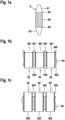
- Figure 1a shows schematically a heat exchanger of the present disclosure.
- Heat exchanger (6) shown in Figure 1a has an inlet chamber (61), a bundle of tubes (62) encased in a shell structure and an outlet chamber (63).
- the inlet chamber (61) and the outlet chamber (63) are separated from the shell structure filled with cooling medium by tube sheets (64) and (65).
- FIGS. 1b and 1c show schematically details of a heat exchanger of the present disclosure.
- Figure 1b shows schematically a cross section through the inlets of three tubes (62) of the heat exchanger (6). Shown are the conical inlets (621) of the tubes (62) and upper regions of the longitudinal middled parts (622) of the tubes (62).
- the tubes (62) are fastened within the heat exchanger (6) by being fixedly connected to tube sheet (64) at the upper ends of the tubes (62).
- the conical inlets (621) of the tubes (62) have been formed by partly removing tube sheet material so that the upper surface of tube sheet (64) between two tubes (62) is three-dimensionally shaped and forms an apex (641) in the middle between two neighboring tubes (62) .
- the ends of the tubes (62) may be welded to the tubes (62) forming a fillet shaped weld seam (642).
- the fillet weld may extend from a front end of the tubes (62) to an inner surface of the respective holes formed on the tube sheet.
- the fillet weld seam (642) may form a continuation of the slope leading to the apex (641). Thus, accumulation of solid particles on the front end of the tubes may be prevented.
- Figure 1c shows schematically a cross section through the outlets of three tubes (62) of the heat exchanger (6). Shown are the even outlets (623) of the tubes (62) and lower regions of the longitudinal middled parts (622) of the tubes (62).
- the tubes (62) are fastened within the heat exchanger (6) by being fixedly connected to tube sheet (65) at the lower ends of the tubes (62).
- the outlets (623) of the tubes (62) are arrange slightly below the lower surface of tube sheet (65).
- Figure 2 shows schematically an apparatus comprising a fluidized bed reactor and a heat exchanger of the present disclosure for carrying out a process for preparing an olefin polymer.
- Fluidized-bed reactor (1) comprises a fluidized bed (11) of polyolefin particles, a gas distribution grid (12) and a velocity reduction zone (13) having an increased diameter compared to the diameter of the fluidized bed portion of the reactor.
- the polyolefin bed is kept in a fluidization state by an upwardly flow of gas fed through the gas distribution grid (12) placed at the bottom of reactor (1).
- the gaseous stream of the reaction gas leaving the top of the velocity reduction zone (13) via the recycle line (3) is compressed by the compressor (4) comprising variable guide vanes (5), transferred to a heat exchanger (6), in which it is cooled, and then recycled to the bottom of the fluidized-bed reactor (1) at a point below the gas distribution grid (12).
- the recycle line (3) further comprises, downstream from the heat exchanger (6), a butterfly valve (7).
- Make-up monomer, molecular weight regulators, and optional inert gases and/or process additives can be fed into the reactor (1) at various positions, for example via line (8) upstream of the compressor (4).
- the fluidized-bed reactor (1) is provided with a continuous pneumatic recycle of polyolefin particles by means of a circulation loop (14) connecting the gas distribution grid (12) to the upper region of the fluidized-bed reactor (1).
- the circulation loop (14) comprises a settling pipe (15) and a pneumatic conveyor pipe (16).
- the settling pipe (15) is integrated with its upper opening into the gas distribution grid (12) and is preferably arranged substantially vertical.
- the gas distribution grid (12) is endowed with a cone shape in such a way that its downward inclination towards the settling pipe (15) fosters the entry of the polyolefin particles into the settling pipe (15) due to gravity.
- the upper opening of the settling pipe (15) is preferably located in a central position with respect to the gas distribution grid (12).
- the carrier gas fed via line (17) for transporting the polyolefin particles through the pneumatic conveyor pipe (16) is taken from the gas recycle line at a point downstream of the compressor (4) and upstream the heat exchanger (6).
- the discharge of polyolefin particles from the fluidized-bed reactor (1) occurs from the settling pipe (15) through discharge conduit (9).
- Figure 3 shows schematically an apparatus comprising a multizone circulating reactor and a heat exchanger of the present disclosure for carrying out a process for preparing an olefin polymer
- the multizone circulating reactor (2) comprises a riser (21) as first reaction zone and a downcomer (22) as second reaction zone.
- the riser (21) and the downcomer (22) are repeatedly passed by the polyolefin particles.
- the polyolefin particles flow upward under fast fluidization conditions and within the downcomer (22), the polyolefin particles flow downward under the action of gravity.
- the riser (21) and the downcomer (22) are appropriately interconnected by the interconnection bends (23) and (24).
- the polyolefin particles and the reaction gas mixture After flowing through the riser (21), the polyolefin particles and the reaction gas mixture leave riser (21) and are conveyed to a solid/gas separation zone (25).
- This solid/gas separation can be effected by using conventional separation means such as, for example, a centrifugal separator like a cyclone. From the separation zone (25) the polyolefin particles move downwards into the downcomer (22).
- a barrier fluid for preventing the reaction gas mixture of the riser (21) from entering the downcomer (22) can be fed into a top part of the downcomer (22) via line (26).
- the reaction gas mixture leaving the separation zone (25) is recycled to the bottom of the riser (21) by means of a recycle line (3), equipped with a compressor (4) comprising variable guide vanes (5) to establish fast fluidization conditions the riser (21).
- the recycle line (3) further comprises a heat exchanger 6) and a butterfly valve (7) downstream of heat exchanger (6).
- Make-up monomers, make-up comonomers, and optionally inert gases and/or process additives can be can be fed into the reactor (2) at various positions, for example via line (8) into the recycle line (3).
- a line (27) branches off and conveys a part of the recycle gas into the interconnection bend (24) for transporting the polyolefin particle from the downcomer (22) to the rise (21).
- the bottom of the downcomer (22) is equipped with a butterfly valve (28) having an adjustable opening for adjusting the flow of polyolefin particles from downcomer (22) through interconnection bend (24) into the riser (21).
- a butterfly valve (28) having an adjustable opening for adjusting the flow of polyolefin particles from downcomer (22) through interconnection bend (24) into the riser (21).
- amounts of a recycle gas mixture coming from the recycle line (3) through lines (26) and (29) are introduced as dosing gas into the downcomer (22) to facilitate the flow of the polyolefin particles through butterfly valve (28).
- the discharge of polyolefin particles from the multizone circulating reactor (2) occurs from the downcomer (22) through discharge conduit (9).
Landscapes
- Engineering & Computer Science (AREA)
- Physics & Mathematics (AREA)
- Thermal Sciences (AREA)
- Mechanical Engineering (AREA)
- General Engineering & Computer Science (AREA)
- Chemical & Material Sciences (AREA)
- Geometry (AREA)
- Health & Medical Sciences (AREA)
- Chemical Kinetics & Catalysis (AREA)
- Medicinal Chemistry (AREA)
- Polymers & Plastics (AREA)
- Organic Chemistry (AREA)
- Polymerisation Methods In General (AREA)
- Heat-Exchange Devices With Radiators And Conduit Assemblies (AREA)
Claims (15)
- Mehrrohriger Wärmetauscher (6) zum Kühlen eines Gasstroms, wobei der Wärmetauscher (6) umfasst:- eine Einlasskammer (61);- ein Bündel von Rohren (62), eingehaust in einer Mantelstruktur; und- eine Auslasskammer (63);wobei jedes Rohr (62) umfasst:- einen Einlass (621);- ein längsgerichtetes Mittelteil (622); und- einen Auslass (623);wobei der Durchmesser d1 des Einlasses (621) von jedem Rohr (62) größer als der Durchmesser d2 des entsprechenden längsgerichteten Mittelteils (622) des Rohrs ist, wobei die Einlässe (621) der Rohre (62) des Wärmetauschers in einen Rohrboden (64) integriert sind, der die Einlasskammer (61) von dem Volumen innerhalb der Mantelstruktur trennt, dadurch gekennzeichnet, dass eine obere Oberfläche des Rohrbodens (64) zwischen zwei Rohren dreidimensional geformt ist, so dass der Rohrboden (64) in der Mitte zwischen zwei benachbarten Rohren einen Scheitel (641) bildet.
- Wärmetauscher (6) nach Anspruch 1, wobei das Verhältnis des Durchmessers d1 zu dem Durchmesser d2 1,75:1 bis 1,5:1, bevorzugter 1,4:1 bis 1,3:1 beträgt.
- Wärmetauscher nach einem der Ansprüche 1 oder 2, wobei der Einlass (621) von jedem Rohr (62) eine konische Form hat.
- Wärmetauscher (6) nach einem der vorhergehenden Ansprüche, wobei der Durchmesser d1 des Einlasses (621) von jedem Rohr (62) 25 bis 45 mm, vorzugsweise 30 bis 40 mm beträgt.
- Wärmetauscher (6) nach einem der vorhergehenden Ansprüche, wobei der Durchmesser d2 des längsgerichteten Mittelteils (622) des Rohrs (62) 10 bis 30 mm, vorzugsweise 15 bis 25 mm beträgt.
- Wärmetauscher (6) nach einem der vorhergehenden Ansprüche, wobei das Bündel von Rohren mindestens 500, vorzugsweise 500 bis 6000 Rohre (62) umfasst.
- Wärmetauscher (6) nach einem der vorhergehenden Ansprüche, wobei der Abstand zwischen den Mittelteilen (622) benachbarter Rohre (62) 25 bis 45 mm, vorzugsweise 30 bis 35 mm beträgt, gemessen von Rohrachse zu Rohrachse.
- Wärmetauscher (6) nach einem der vorhergehenden Ansprüche, wobei der Winkel zwischen dem Konusbereich und der Zentralachse des Rohrs vorzugsweise im Bereich von 20° bis 60°, bevorzugter 30° bis 50° liegt und insbesondere 45° beträgt.
- Wärmetauscher (6) nach einem der vorhergehenden Ansprüche, wobei der Rohrboden (64) ein Loch für jedes Rohr (62) umfasst, wobei das Rohr (62) teilweise in dem jeweilige Loch aufgenommen wird, und wobei das Loch mindestens teilweise in Richtung der oberen Oberfläche zuläuft, die die Einlässe (621) der Rohre (62) bildet, und einen spitz zulaufenden Scheitel (641) zwischen benachbarten Rohren (62) bildet.
- Wärmetauscher (6) nach einem der vorhergehenden Ansprüche, wobei die innere Oberfläche der Rohre (62) und/oder die Oberflächen der Einlasskammer (61) und der Auslasskammer (63) eine Oberflächenrauheit Ra von weniger als 7 µm, vorzugsweise weniger als 3 µm, insbesondere weniger als 2 µm hat/haben, bestimmt gemäß ASTM B46.1.
- Vorrichtung zur Gasphasenpolymerisation von Olefinen, wobei die Vorrichtung umfasst:- einen Reaktor (1, 2), umfassend mindestens eine Polymerisationszone;- eine Recyclingleitung (3) zum Abziehen von Reaktionsgas aus dem Reaktor (1, 2) und Rückspeisen des Reaktionsgases in den Reaktor (1, 2);- einen Kompressor (4) zum Fördern des Reaktionsgases entlang der Recyclingleitung (3); und- einen Wärmetauscher (6) zum Kühlen des Reaktionsgases,wobei der Wärmetauscher (6) der Wärmetauscher gemäß einem der Ansprüche 1 bis 10 ist.
- Vorrichtung nach Anspruch 11, wobei die Vorrichtung des Weiteren ein Drosselventil (7) umfasst, das nachgeordnet zu dem Wärmetauscher (6) angeordnet ist.
- Vorrichtung nach Anspruch 11 oder 12, wobei der Reaktor ein Wirbelbettreaktor ist.
- Vorrichtung nach Anspruch 11 oder 12, wobei der Reaktor ein mehrzoniger Umlaufreaktor (2) ist, wobei in einer ersten Polymerisationszone (21) wachsende Polyolefinpartikel unter raschen Verwirbelungs- oder Transportbedingungen aufwärts fließen, und wobei in einer zweiten Polymerisationszone (22) wachsende Polyolefinpartikel in einer verdichteten Form abwärts fließen, wobei die erste Polymerisationszone (21) und die zweite Polymerisationszone (22) miteinander verbunden sind, und Polyolefinpartikel, die die erste Polymerisationszone (21) verlassen, in die zweite Polymerisationszone (22) eintreten, und Polyolefinpartikel, die die zweite Polymerisationszone (22) verlassen, in die erste Polymerisationszone (21) eintreten, wodurch eine Zirkulation von Polyolefinpartikeln durch die erste und die zweite Polymerisationszone (21, 22) errichtet wird.
- Verfahren zur Herstellung eines Olefinpolymers, umfassend Homopolymerisieren eines Olefins oder Copolymeriseren eines Olefins und eines oder mehrerer anderer Olefine bei Temperaturen von 20 bis 200 °C und Drücken von 0,5 bis 10 MPa in Gegenwart eines Polymerisationskatalysators, wobei das Verfahren in der Vorrichtung nach einem der Ansprüche 11 bis 14 durchgeführt wird.
Applications Claiming Priority (2)
| Application Number | Priority Date | Filing Date | Title |
|---|---|---|---|
| EP21178380.8A EP4102166A1 (de) | 2021-06-08 | 2021-06-08 | Wärmetauscher für gasphasenpolymerisierung |
| PCT/EP2022/065432 WO2022258633A1 (en) | 2021-06-08 | 2022-06-07 | Heat exchanger for gas phase polymerization |
Publications (2)
| Publication Number | Publication Date |
|---|---|
| EP4314686A1 EP4314686A1 (de) | 2024-02-07 |
| EP4314686B1 true EP4314686B1 (de) | 2024-08-21 |
Family
ID=76355315
Family Applications (2)
| Application Number | Title | Priority Date | Filing Date |
|---|---|---|---|
| EP21178380.8A Withdrawn EP4102166A1 (de) | 2021-06-08 | 2021-06-08 | Wärmetauscher für gasphasenpolymerisierung |
| EP22731706.2A Active EP4314686B1 (de) | 2021-06-08 | 2022-06-07 | Wärmetauscher für gasphasenpolymerisierung |
Family Applications Before (1)
| Application Number | Title | Priority Date | Filing Date |
|---|---|---|---|
| EP21178380.8A Withdrawn EP4102166A1 (de) | 2021-06-08 | 2021-06-08 | Wärmetauscher für gasphasenpolymerisierung |
Country Status (8)
| Country | Link |
|---|---|
| US (1) | US20240271876A1 (de) |
| EP (2) | EP4102166A1 (de) |
| JP (1) | JP7693843B2 (de) |
| KR (1) | KR102720291B1 (de) |
| CN (1) | CN117597562A (de) |
| BR (1) | BR112023025158A2 (de) |
| SA (1) | SA523451793B1 (de) |
| WO (1) | WO2022258633A1 (de) |
Family Cites Families (22)
| Publication number | Priority date | Publication date | Assignee | Title |
|---|---|---|---|---|
| CH276825A (de) * | 1949-10-27 | 1951-07-31 | Escher Wyss Ag | Wärmeaustauscher. |
| US4588790A (en) | 1982-03-24 | 1986-05-13 | Union Carbide Corporation | Method for fluidized bed polymerization |
| JPS59122898A (ja) * | 1982-12-27 | 1984-07-16 | Toshiba Corp | 熱交換器 |
| IT1275573B (it) | 1995-07-20 | 1997-08-07 | Spherilene Spa | Processo ed apparecchiatura per la pomimerizzazione in fase gas delle alfa-olefine |
| JPH09133491A (ja) * | 1995-11-06 | 1997-05-20 | Sanyo Electric Co Ltd | 熱交換器の製造方法 |
| JPH09273703A (ja) * | 1996-04-03 | 1997-10-21 | Hitachi Ltd | 発電プラントの流路管 |
| CN1137142C (zh) | 1998-07-08 | 2004-02-04 | 蒙特尔技术有限公司 | 气相聚合的方法和设备 |
| FR2791983B1 (fr) | 1999-04-12 | 2001-05-18 | Bp Chemicals Snc | Appareil et procede de polymerisation en phase gazeuse d'olefine |
| US7377039B2 (en) * | 2003-05-29 | 2008-05-27 | Saudi Arabian Oil Company | Anti-corrosion protection for heat exchanger tube sheet and method of manufacture |
| DE10333577A1 (de) * | 2003-07-24 | 2005-02-24 | Bayer Technology Services Gmbh | Verfahren und Vorrichtung zur Entfernung von flüchtigen Substanzen aus hochviskosen Medien |
| DE102004041375A1 (de) * | 2004-03-24 | 2005-10-13 | Coperion Waeschle Gmbh & Co. Kg | Vorrichtung zum Temperieren von Schüttgut |
| KR200406359Y1 (ko) * | 2005-10-12 | 2006-01-20 | 범우이엔지 주식회사 | 열교환기의 튜브 구조 |
| BRPI0621073B1 (pt) | 2005-12-23 | 2017-12-05 | Basell Poliolefine Italia S.R.L. | Gas phase process and apparatus for polymerization of olefins |
| DE102006003317B4 (de) * | 2006-01-23 | 2008-10-02 | Alstom Technology Ltd. | Rohrbündel-Wärmetauscher |
| DE102007015060A1 (de) * | 2007-03-26 | 2008-10-02 | Coperion Waeschle Gmbh & Co. Kg | Vorrichtung zum Kühlen und/oder Heizen von Schüttgut |
| US20130300038A1 (en) * | 2012-05-10 | 2013-11-14 | Alstom Technology Ltd | Integrated gas cooling system for electric arc furnace |
| DE102012012939A1 (de) * | 2012-06-29 | 2014-04-24 | Mann + Hummel Gmbh | Wärmetauscher zur Kühlung eines Fluids einer Brennkraftmaschine, Anordnung mit wenigstens einem Wärmetauscher und Verfahren zur Herstellung eines Wärmetauschers |
| CN204461187U (zh) | 2015-01-30 | 2015-07-08 | 永胜机械工业(昆山)有限公司 | 热交换器换热管板接头 |
| US9829214B2 (en) * | 2015-04-22 | 2017-11-28 | Ronald Paul Taylor | Cylindrical tubular heat exchanger type 1 |
| DE102015013517A1 (de) * | 2015-10-20 | 2017-04-20 | Borsig Gmbh | Wärmeübertrager |
| EP3499171A1 (de) * | 2017-12-15 | 2019-06-19 | ALFA LAVAL OLMI S.p.A. | Erosionsschutzvorrichtung für eine mantel-rohr-ausrüstung |
| EP3524343A1 (de) * | 2018-02-07 | 2019-08-14 | Basell Polyolefine GmbH | Verfahren zur polymerisation von olefinen in der gasphase |
-
2021
- 2021-06-08 EP EP21178380.8A patent/EP4102166A1/de not_active Withdrawn
-
2022
- 2022-06-07 WO PCT/EP2022/065432 patent/WO2022258633A1/en not_active Ceased
- 2022-06-07 BR BR112023025158A patent/BR112023025158A2/pt unknown
- 2022-06-07 KR KR1020237042745A patent/KR102720291B1/ko active Active
- 2022-06-07 JP JP2023573580A patent/JP7693843B2/ja active Active
- 2022-06-07 CN CN202280038888.0A patent/CN117597562A/zh active Pending
- 2022-06-07 EP EP22731706.2A patent/EP4314686B1/de active Active
- 2022-06-07 US US18/568,147 patent/US20240271876A1/en active Pending
-
2023
- 2023-12-03 SA SA523451793A patent/SA523451793B1/ar unknown
Also Published As
| Publication number | Publication date |
|---|---|
| EP4314686A1 (de) | 2024-02-07 |
| KR102720291B1 (ko) | 2024-10-21 |
| CN117597562A (zh) | 2024-02-23 |
| EP4102166A1 (de) | 2022-12-14 |
| US20240271876A1 (en) | 2024-08-15 |
| BR112023025158A2 (pt) | 2024-02-27 |
| JP7693843B2 (ja) | 2025-06-17 |
| KR20230172614A (ko) | 2023-12-22 |
| JP2024520110A (ja) | 2024-05-21 |
| SA523451793B1 (ar) | 2025-01-07 |
| WO2022258633A1 (en) | 2022-12-15 |
Similar Documents
| Publication | Publication Date | Title |
|---|---|---|
| EP3723898B1 (de) | Verfahren zur polymerisation von olefinen in der gasphase | |
| EP2723781B1 (de) | Verfahren und vorrichtung zum austragen eines polymers aus einem gasphasenreaktor | |
| TW200836837A (en) | Gas distribution grid for a polymerization apparatus | |
| US9410001B2 (en) | Recycle gas cooler systems for gas-phase polymerization processes | |
| CN101268104B (zh) | 用于烯烃聚合反应的气相方法 | |
| EP4314686B1 (de) | Wärmetauscher für gasphasenpolymerisierung | |
| KR102904906B1 (ko) | 기상 중합 장치 | |
| US12337310B2 (en) | Apparatus and process for the gas-phase polymerization | |
| EP4438168A1 (de) | Wirbelschichtreaktor zur gasphasenpolymerisation von olefinen | |
| RU2786067C1 (ru) | Устройство и способ для газофазной полимеризации | |
| JP2023554278A (ja) | オレフィン気相重合用反応器 | |
| EP2745927A1 (de) | Fließbettreaktor mit interner Wanderbettreaktionseinheit |
Legal Events
| Date | Code | Title | Description |
|---|---|---|---|
| STAA | Information on the status of an ep patent application or granted ep patent |
Free format text: STATUS: UNKNOWN |
|
| STAA | Information on the status of an ep patent application or granted ep patent |
Free format text: STATUS: THE INTERNATIONAL PUBLICATION HAS BEEN MADE |
|
| PUAI | Public reference made under article 153(3) epc to a published international application that has entered the european phase |
Free format text: ORIGINAL CODE: 0009012 |
|
| STAA | Information on the status of an ep patent application or granted ep patent |
Free format text: STATUS: REQUEST FOR EXAMINATION WAS MADE |
|
| 17P | Request for examination filed |
Effective date: 20231101 |
|
| AK | Designated contracting states |
Kind code of ref document: A1 Designated state(s): AL AT BE BG CH CY CZ DE DK EE ES FI FR GB GR HR HU IE IS IT LI LT LU LV MC MK MT NL NO PL PT RO RS SE SI SK SM TR |
|
| GRAP | Despatch of communication of intention to grant a patent |
Free format text: ORIGINAL CODE: EPIDOSNIGR1 |
|
| STAA | Information on the status of an ep patent application or granted ep patent |
Free format text: STATUS: GRANT OF PATENT IS INTENDED |
|
| INTG | Intention to grant announced |
Effective date: 20240418 |
|
| GRAS | Grant fee paid |
Free format text: ORIGINAL CODE: EPIDOSNIGR3 |
|
| GRAA | (expected) grant |
Free format text: ORIGINAL CODE: 0009210 |
|
| STAA | Information on the status of an ep patent application or granted ep patent |
Free format text: STATUS: THE PATENT HAS BEEN GRANTED |
|
| DAV | Request for validation of the european patent (deleted) | ||
| DAX | Request for extension of the european patent (deleted) | ||
| AK | Designated contracting states |
Kind code of ref document: B1 Designated state(s): AL AT BE BG CH CY CZ DE DK EE ES FI FR GB GR HR HU IE IS IT LI LT LU LV MC MK MT NL NO PL PT RO RS SE SI SK SM TR |
|
| REG | Reference to a national code |
Ref country code: GB Ref legal event code: FG4D |
|
| REG | Reference to a national code |
Ref country code: CH Ref legal event code: EP |
|
| REG | Reference to a national code |
Ref country code: DE Ref legal event code: R096 Ref document number: 602022005525 Country of ref document: DE |
|
| REG | Reference to a national code |
Ref country code: IE Ref legal event code: FG4D |
|
| P01 | Opt-out of the competence of the unified patent court (upc) registered |
Free format text: CASE NUMBER: APP_47024/2024 Effective date: 20240814 |
|
| REG | Reference to a national code |
Ref country code: LT Ref legal event code: MG9D |
|
| REG | Reference to a national code |
Ref country code: NL Ref legal event code: MP Effective date: 20240821 |
|
| PG25 | Lapsed in a contracting state [announced via postgrant information from national office to epo] |
Ref country code: NO Free format text: LAPSE BECAUSE OF FAILURE TO SUBMIT A TRANSLATION OF THE DESCRIPTION OR TO PAY THE FEE WITHIN THE PRESCRIBED TIME-LIMIT Effective date: 20241121 |
|
| REG | Reference to a national code |
Ref country code: AT Ref legal event code: MK05 Ref document number: 1715860 Country of ref document: AT Kind code of ref document: T Effective date: 20240821 |
|
| PG25 | Lapsed in a contracting state [announced via postgrant information from national office to epo] |
Ref country code: PL Free format text: LAPSE BECAUSE OF FAILURE TO SUBMIT A TRANSLATION OF THE DESCRIPTION OR TO PAY THE FEE WITHIN THE PRESCRIBED TIME-LIMIT Effective date: 20240821 Ref country code: FI Free format text: LAPSE BECAUSE OF FAILURE TO SUBMIT A TRANSLATION OF THE DESCRIPTION OR TO PAY THE FEE WITHIN THE PRESCRIBED TIME-LIMIT Effective date: 20240821 Ref country code: NL Free format text: LAPSE BECAUSE OF FAILURE TO SUBMIT A TRANSLATION OF THE DESCRIPTION OR TO PAY THE FEE WITHIN THE PRESCRIBED TIME-LIMIT Effective date: 20240821 Ref country code: GR Free format text: LAPSE BECAUSE OF FAILURE TO SUBMIT A TRANSLATION OF THE DESCRIPTION OR TO PAY THE FEE WITHIN THE PRESCRIBED TIME-LIMIT Effective date: 20241122 Ref country code: PT Free format text: LAPSE BECAUSE OF FAILURE TO SUBMIT A TRANSLATION OF THE DESCRIPTION OR TO PAY THE FEE WITHIN THE PRESCRIBED TIME-LIMIT Effective date: 20241223 |
|
| PG25 | Lapsed in a contracting state [announced via postgrant information from national office to epo] |
Ref country code: BG Free format text: LAPSE BECAUSE OF FAILURE TO SUBMIT A TRANSLATION OF THE DESCRIPTION OR TO PAY THE FEE WITHIN THE PRESCRIBED TIME-LIMIT Effective date: 20240821 |
|
| PG25 | Lapsed in a contracting state [announced via postgrant information from national office to epo] |
Ref country code: LV Free format text: LAPSE BECAUSE OF FAILURE TO SUBMIT A TRANSLATION OF THE DESCRIPTION OR TO PAY THE FEE WITHIN THE PRESCRIBED TIME-LIMIT Effective date: 20240821 |
|
| PG25 | Lapsed in a contracting state [announced via postgrant information from national office to epo] |
Ref country code: AT Free format text: LAPSE BECAUSE OF FAILURE TO SUBMIT A TRANSLATION OF THE DESCRIPTION OR TO PAY THE FEE WITHIN THE PRESCRIBED TIME-LIMIT Effective date: 20240821 Ref country code: IS Free format text: LAPSE BECAUSE OF FAILURE TO SUBMIT A TRANSLATION OF THE DESCRIPTION OR TO PAY THE FEE WITHIN THE PRESCRIBED TIME-LIMIT Effective date: 20241221 |
|
| PG25 | Lapsed in a contracting state [announced via postgrant information from national office to epo] |
Ref country code: HR Free format text: LAPSE BECAUSE OF FAILURE TO SUBMIT A TRANSLATION OF THE DESCRIPTION OR TO PAY THE FEE WITHIN THE PRESCRIBED TIME-LIMIT Effective date: 20240821 |
|
| PG25 | Lapsed in a contracting state [announced via postgrant information from national office to epo] |
Ref country code: ES Free format text: LAPSE BECAUSE OF FAILURE TO SUBMIT A TRANSLATION OF THE DESCRIPTION OR TO PAY THE FEE WITHIN THE PRESCRIBED TIME-LIMIT Effective date: 20240821 Ref country code: RS Free format text: LAPSE BECAUSE OF FAILURE TO SUBMIT A TRANSLATION OF THE DESCRIPTION OR TO PAY THE FEE WITHIN THE PRESCRIBED TIME-LIMIT Effective date: 20241121 |
|
| PG25 | Lapsed in a contracting state [announced via postgrant information from national office to epo] |
Ref country code: RS Free format text: LAPSE BECAUSE OF FAILURE TO SUBMIT A TRANSLATION OF THE DESCRIPTION OR TO PAY THE FEE WITHIN THE PRESCRIBED TIME-LIMIT Effective date: 20241121 Ref country code: PT Free format text: LAPSE BECAUSE OF FAILURE TO SUBMIT A TRANSLATION OF THE DESCRIPTION OR TO PAY THE FEE WITHIN THE PRESCRIBED TIME-LIMIT Effective date: 20241223 Ref country code: PL Free format text: LAPSE BECAUSE OF FAILURE TO SUBMIT A TRANSLATION OF THE DESCRIPTION OR TO PAY THE FEE WITHIN THE PRESCRIBED TIME-LIMIT Effective date: 20240821 Ref country code: NO Free format text: LAPSE BECAUSE OF FAILURE TO SUBMIT A TRANSLATION OF THE DESCRIPTION OR TO PAY THE FEE WITHIN THE PRESCRIBED TIME-LIMIT Effective date: 20241121 Ref country code: NL Free format text: LAPSE BECAUSE OF FAILURE TO SUBMIT A TRANSLATION OF THE DESCRIPTION OR TO PAY THE FEE WITHIN THE PRESCRIBED TIME-LIMIT Effective date: 20240821 Ref country code: LV Free format text: LAPSE BECAUSE OF FAILURE TO SUBMIT A TRANSLATION OF THE DESCRIPTION OR TO PAY THE FEE WITHIN THE PRESCRIBED TIME-LIMIT Effective date: 20240821 Ref country code: IS Free format text: LAPSE BECAUSE OF FAILURE TO SUBMIT A TRANSLATION OF THE DESCRIPTION OR TO PAY THE FEE WITHIN THE PRESCRIBED TIME-LIMIT Effective date: 20241221 Ref country code: HR Free format text: LAPSE BECAUSE OF FAILURE TO SUBMIT A TRANSLATION OF THE DESCRIPTION OR TO PAY THE FEE WITHIN THE PRESCRIBED TIME-LIMIT Effective date: 20240821 Ref country code: GR Free format text: LAPSE BECAUSE OF FAILURE TO SUBMIT A TRANSLATION OF THE DESCRIPTION OR TO PAY THE FEE WITHIN THE PRESCRIBED TIME-LIMIT Effective date: 20241122 Ref country code: FI Free format text: LAPSE BECAUSE OF FAILURE TO SUBMIT A TRANSLATION OF THE DESCRIPTION OR TO PAY THE FEE WITHIN THE PRESCRIBED TIME-LIMIT Effective date: 20240821 Ref country code: ES Free format text: LAPSE BECAUSE OF FAILURE TO SUBMIT A TRANSLATION OF THE DESCRIPTION OR TO PAY THE FEE WITHIN THE PRESCRIBED TIME-LIMIT Effective date: 20240821 Ref country code: BG Free format text: LAPSE BECAUSE OF FAILURE TO SUBMIT A TRANSLATION OF THE DESCRIPTION OR TO PAY THE FEE WITHIN THE PRESCRIBED TIME-LIMIT Effective date: 20240821 Ref country code: AT Free format text: LAPSE BECAUSE OF FAILURE TO SUBMIT A TRANSLATION OF THE DESCRIPTION OR TO PAY THE FEE WITHIN THE PRESCRIBED TIME-LIMIT Effective date: 20240821 |
|
| PG25 | Lapsed in a contracting state [announced via postgrant information from national office to epo] |
Ref country code: DK Free format text: LAPSE BECAUSE OF FAILURE TO SUBMIT A TRANSLATION OF THE DESCRIPTION OR TO PAY THE FEE WITHIN THE PRESCRIBED TIME-LIMIT Effective date: 20240821 Ref country code: SM Free format text: LAPSE BECAUSE OF FAILURE TO SUBMIT A TRANSLATION OF THE DESCRIPTION OR TO PAY THE FEE WITHIN THE PRESCRIBED TIME-LIMIT Effective date: 20240821 Ref country code: RO Free format text: LAPSE BECAUSE OF FAILURE TO SUBMIT A TRANSLATION OF THE DESCRIPTION OR TO PAY THE FEE WITHIN THE PRESCRIBED TIME-LIMIT Effective date: 20240821 |
|
| PG25 | Lapsed in a contracting state [announced via postgrant information from national office to epo] |
Ref country code: EE Free format text: LAPSE BECAUSE OF FAILURE TO SUBMIT A TRANSLATION OF THE DESCRIPTION OR TO PAY THE FEE WITHIN THE PRESCRIBED TIME-LIMIT Effective date: 20240821 |
|
| PG25 | Lapsed in a contracting state [announced via postgrant information from national office to epo] |
Ref country code: CZ Free format text: LAPSE BECAUSE OF FAILURE TO SUBMIT A TRANSLATION OF THE DESCRIPTION OR TO PAY THE FEE WITHIN THE PRESCRIBED TIME-LIMIT Effective date: 20240821 |
|
| PG25 | Lapsed in a contracting state [announced via postgrant information from national office to epo] |
Ref country code: SK Free format text: LAPSE BECAUSE OF FAILURE TO SUBMIT A TRANSLATION OF THE DESCRIPTION OR TO PAY THE FEE WITHIN THE PRESCRIBED TIME-LIMIT Effective date: 20240821 Ref country code: IT Free format text: LAPSE BECAUSE OF FAILURE TO SUBMIT A TRANSLATION OF THE DESCRIPTION OR TO PAY THE FEE WITHIN THE PRESCRIBED TIME-LIMIT Effective date: 20240821 |
|
| REG | Reference to a national code |
Ref country code: DE Ref legal event code: R097 Ref document number: 602022005525 Country of ref document: DE |
|
| PLBE | No opposition filed within time limit |
Free format text: ORIGINAL CODE: 0009261 |
|
| STAA | Information on the status of an ep patent application or granted ep patent |
Free format text: STATUS: NO OPPOSITION FILED WITHIN TIME LIMIT |
|
| PGFP | Annual fee paid to national office [announced via postgrant information from national office to epo] |
Ref country code: DE Payment date: 20250509 Year of fee payment: 4 |
|
| PGFP | Annual fee paid to national office [announced via postgrant information from national office to epo] |
Ref country code: BE Payment date: 20250513 Year of fee payment: 4 |
|
| PGFP | Annual fee paid to national office [announced via postgrant information from national office to epo] |
Ref country code: FR Payment date: 20250512 Year of fee payment: 4 |
|
| 26N | No opposition filed |
Effective date: 20250522 |
|
| PG25 | Lapsed in a contracting state [announced via postgrant information from national office to epo] |
Ref country code: SE Free format text: LAPSE BECAUSE OF FAILURE TO SUBMIT A TRANSLATION OF THE DESCRIPTION OR TO PAY THE FEE WITHIN THE PRESCRIBED TIME-LIMIT Effective date: 20240821 |
|
| REG | Reference to a national code |
Ref country code: CH Ref legal event code: H13 Free format text: ST27 STATUS EVENT CODE: U-0-0-H10-H13 (AS PROVIDED BY THE NATIONAL OFFICE) Effective date: 20260127 |
|
| PG25 | Lapsed in a contracting state [announced via postgrant information from national office to epo] |
Ref country code: MC Free format text: LAPSE BECAUSE OF FAILURE TO SUBMIT A TRANSLATION OF THE DESCRIPTION OR TO PAY THE FEE WITHIN THE PRESCRIBED TIME-LIMIT Effective date: 20240821 |
|
| PG25 | Lapsed in a contracting state [announced via postgrant information from national office to epo] |
Ref country code: LU Free format text: LAPSE BECAUSE OF NON-PAYMENT OF DUE FEES Effective date: 20250607 |
|
| PG25 | Lapsed in a contracting state [announced via postgrant information from national office to epo] |
Ref country code: IE Free format text: LAPSE BECAUSE OF NON-PAYMENT OF DUE FEES Effective date: 20250607 |