EP4313841B1 - Anlage für sicheren zugang zu einem oberen teil eines fahrzeugs - Google Patents
Anlage für sicheren zugang zu einem oberen teil eines fahrzeugs Download PDFInfo
- Publication number
- EP4313841B1 EP4313841B1 EP22715072.9A EP22715072A EP4313841B1 EP 4313841 B1 EP4313841 B1 EP 4313841B1 EP 22715072 A EP22715072 A EP 22715072A EP 4313841 B1 EP4313841 B1 EP 4313841B1
- Authority
- EP
- European Patent Office
- Prior art keywords
- platform
- installation
- longitudinal
- support
- movable
- Prior art date
- Legal status (The legal status is an assumption and is not a legal conclusion. Google has not performed a legal analysis and makes no representation as to the accuracy of the status listed.)
- Active
Links
Images


Classifications
-
- B—PERFORMING OPERATIONS; TRANSPORTING
- B66—HOISTING; LIFTING; HAULING
- B66F—HOISTING, LIFTING, HAULING OR PUSHING, NOT OTHERWISE PROVIDED FOR, e.g. DEVICES WHICH APPLY A LIFTING OR PUSHING FORCE DIRECTLY TO THE SURFACE OF A LOAD
- B66F11/00—Lifting devices specially adapted for particular uses not otherwise provided for
- B66F11/04—Lifting devices specially adapted for particular uses not otherwise provided for for movable platforms or cabins, e.g. on vehicles, permitting workmen to place themselves in any desired position for carrying out required operations
-
- E—FIXED CONSTRUCTIONS
- E04—BUILDING
- E04G—SCAFFOLDING; FORMS; SHUTTERING; BUILDING IMPLEMENTS OR AIDS, OR THEIR USE; HANDLING BUILDING MATERIALS ON THE SITE; REPAIRING, BREAKING-UP OR OTHER WORK ON EXISTING BUILDINGS
- E04G1/00—Scaffolds primarily resting on the ground
- E04G1/18—Scaffolds primarily resting on the ground adjustable in height
- E04G1/20—Scaffolds comprising upright members and provision for supporting cross-members or platforms at different positions therealong
-
- E—FIXED CONSTRUCTIONS
- E04—BUILDING
- E04G—SCAFFOLDING; FORMS; SHUTTERING; BUILDING IMPLEMENTS OR AIDS, OR THEIR USE; HANDLING BUILDING MATERIALS ON THE SITE; REPAIRING, BREAKING-UP OR OTHER WORK ON EXISTING BUILDINGS
- E04G1/00—Scaffolds primarily resting on the ground
- E04G1/18—Scaffolds primarily resting on the ground adjustable in height
- E04G1/22—Scaffolds having a platform on an extensible substructure, e.g. of telescopic type or with lazy-tongs mechanism
Definitions
- This invention relates to an installation for secure access to an upper part of a vehicle, said installation comprising, a fixed frame arranged along a line of passage for said vehicle, a vertically movable support structure, movable relative to the fixed frame, at least one longitudinal platform supported by said movable support structure, a first actuating device having one fixed part fixed relative to the fixed frame and a movable part attached to said movable support structure, to arrange for vertical movement, of the movable support structure, a second actuating device having one part attached to a first fixing means fixated to said movable support structure and another part attached to a second fixing means attached to said longitudinal platform, to arrange for horizontal movement of the longitudinal platform.
- At least one laterally extending platform/"bridge which enables staff to easily move from a longitudinal platform arranged along one side of a vehicle to the other side of the vehicle without the need to first move down to the ground floor. Furthermore, such an installation provides the possibility to merely use one stair way application instead of two as is needed with conventional installations.
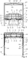
- FIG. 1 there is shown a perspective view of a bus service workshop 1 proved with two installations 2, 2' in accordance with one embodiment of the invention.
- the two installations 2, 2' have the same design and are arranged parallelly in order to provide for the possibility to service two vehicles B at the same time.
- the installations 2, 2' are arranged with movable platforms 5, 6, 5', 6', which are shown to be positioned on different heights in the figure, to clearly show that the platforms 5, 6, 5', 6' are adjustably positioned on any desired height within a given range provided by the installation 2, 2'.
- the installation 2 includes a fixed frame structure 3.
- the fixed frame structure 3 comprises four uprights 30 positioned at each end of a rectangular area that is created by the frame structure of the installation 2, when seen from above.
- At the top of the uprights 30 there are arranged two parallel longitudinal frame works 31 and also two parallel lateral frame works 32. Accordingly, the frame works 31, 32 are interconnected via the uprights 30 to form a rectangle at the top of the uprights 30.
- the height h of the uprights are sufficiently high to provide for entry of a vehicle to easily pass underneath the platforms 5, 6 when the platforms 5, 6 are positioned in their uppermost position.
- the top end of the uprights 30 are positioned at a level within the range of 6-7 m above the ground floor GF, i.e. the ground floor for a vehicle to drive into and out of the installation along a line of passage C.
- the width W of the installation 2 is defined by the outer sides of the uprights 30, which preferably positioned such that the width W is in the range of 5-6 m which provides for sufficient space for vehicles to enter into the installation 2.
- the length L of the installation between two longitudinally uprights 30 may be relatively large, which provides for the advantage that there will be provided an open space between each pair of the longitudinal uprights.
- the distance L between two longitudinally uprights is at least 10 m, preferably in the range of 13-23 m.
- the clearance width between a pair of uprights is preferably at least 4,5 m, more preferred 4,8-5,4 m.
- Maximal clearance width between the two longitudinal platforms 5 is at least 3 m, preferably in the range of 3,1-3,5 m. Adjustable clearance height below the platforms 5, 6 is preferably within the range of 1-5 m, more preferred within 1,2-4,2 m.
- the movable support structure 4 includes two horizontally extending support beams 40. Each support beam 40 extends transversally in relation to the line of passage C, between a pair of uprights 30. An anchoring device 41 is arranged at each end 40A of the support beams 40 that provides for the ability to move the support beams 40 vertically along the uprights 30 and that fixates the support beams 40 in any other direction, i.e. provides a stable guidance to merely provide vertical movement.
- each platform 5 is arranged with flooring 52 for staff to move on longitudinally along the installation 2. Further there are arranged support fences 51 to safeguard staff moving on the platform 5, to not fall down. Also, there are cushioning members 83, 84 positioned at the inner edges of the longitudinal platforms 5 that enable the platforms to be positioned in contact with a vehicle B without damaging the vehicle and also closing the space between the platform and the vehicle B so that there exists no gap.
- Each anchoring mechanism 41 interacts with guide rails 412, 413 (see Fig. 6 ) within each upright 30, such that vertical movement is facilitated at the same time as the anchoring mechanism 41 is fixed in other directions.
- the anchoring mechanism 41 includes a cardanic joint 46, such that bending forces from the support beams 40 onto the anchoring mechanism 41will not transfer any bending forces into the guiding members 411, 414, 412, 413 of the anchoring mechanism 41.
- Fig. 1 there may also be arranged upper transversal support beams 33 provided at an angle, forming V-shapes along the upper top side of the fixed support structure 3.
- These additional support members 33 are preferably provided in connection with having a crane beam 9 arranged within the installation 2.
- a hoist (not shown) that is movably arranged along the crane beam 9 such that the hoist may be moved from one side to the other within the installation 2.
- the crane beam 9 may be provided with low friction members 90 (e.g. rollers) at each end to be movably arranged along the longitudinal frame works 31, such that the crane beam 9 may be moved and positioned at any desired location in the longitudinal direction within the installation 2.
- Fig. 2 there is shown alternatively arranged installations 2, 2' in a service workshop 1 basically providing the same function as described in connection with Fig. 1 .
- the difference compared to Fig. 1 is that the two installations 2, 2' shown in Fig.2 may be provided with a crane beam (not shown) that extends across both installations 2, 2'. This may be achieved by not using any longitudinal frame work members 31 at the central part of the joint installations 2, 2', such that a hoist not shown may be moved in between the outer two longitudinal frame work member 31, 31' of the two installations 2, 2'.
- FIGs. 1 and 2 shown perspective views of stairways 7 that may form a part of the concept according to the invention. It is how that the stairway comprises a lower static part 7A and an upper adjustable part 7B. At the top of the upper part 7B there is a platform 72. The platform 72 may be adjustably positioned on different vertical heights by means of a hydraulic cylinder 70 (see Fig. 11 ).
- the stairway 7 includes two stairway uprights 71 that include guiding members for controlled guided movement of the upper part 7B of the stairway 7.
- support legs 76 e.g. in the form of an up and down turned U.
- Fig. 3 there is shown a front view of an installation according to the invention as shown in Fig. 1 .
- a preferred structure of the frame work which includes an upper frame work beam 320, a lower frame work beam 323 and intermediate frame work members 321, 322 interconnecting the upper and lower frame work beams 321, 323.
- the height h3 of each frame work 32 is in the range of 0,4-0,7 m and each frame work beam preferably has a hollow cross- sectional shape, preferably square tube, having a maximum outer cross-sectional width within the range of 80 to 140 mm (i.e. sides of a square tube within 50-100 mm).
- each upright 30 is arranged with longitudinal holes 305, which provide for the ability to securely attach guide members 412, 413 (see Fig. 6 ) within the uprights 30.
- each carrying member 50 is arranged with an attachment member 43 that provides attachment of one end of a hydraulic cylinder 42.
- the other end of the hydraulic cylinder 42 is attached to a first fixing member 44 that is fixed onto support beam 40.
- the actuating device 42 here hydraulic cylinder
- the actuating device 42 has one fixed part 420 and one movable part 421. (see Fig. 6 )
- the transversal platform 6 comprises two parts 6A, 6B, which are telescopically arranged such that when transversal movement of a longitudinal platform 5 is performed, the size of the transversal platform 6 will adapt to the transversal distance between the two platforms 5.
- a central part 60 that is telescopically interacting with outer parts 633, 643, preferably by means of wheel/rollers (not shown) to minimize friction.
- outer parts 633, 643 preferably by means of wheel/rollers (not shown) to minimize friction.
- Each longitudinal platform 5, at its outer side, is arranged with a supporting longitudinal wall 53, which fulfil more than one function.
- a first function is that it will provide sufficient strength to make the platform 5 self-supporting, resulting in the advantage that no external support is needed at any intermediate position between the two support beams 40 for the platform 5.
- the longitudinal wall 53 is provided with sufficient height h5 (see Fig. 8 ), at least 0,3 m.
- the height is at least 0,35 m, more preferred in the range of 0,4 - 1 m and the thickness is preferably less than 3% in relation to the height h5, e.g. in the range of 8-15 mm for steel plate.
- the height h5 of the side plate 53 is larger adjacent the middle of the platform 5 than adjacent the ends, which provides the advantage that sufficient strength may be achieved at a lower total weight than if a straight upper edge 53A is used.
- a second function of the height of the side plate 53 is that it hinders objects to fall down from the platform 5 out over the edge, which otherwise may cause injury, by having its lower end 53B at or below the level of the floor 52 of the platform 5.
- a similar function is achieved by the transversal side plates 54 arranged at the end of each platform 5, which also protrude above the floor area 52 of the platform 5.
- Fig. 4 there is shown a front view of an installation 2 according to the invention where one side of each upright 30 has been removed.
- the hydraulic cylinder 45 has a fixed cylinder part 450, which is fixedly attached in relation to the fixed frame 3. As shown in Fig. 4 this may be achieved by positioning the lower end 451 of the cylinder 450 to form the fixed part, e.g. to be positioned onto ground floor GF.
- the hydraulic cylinder 45 has a movable part, i.e. a piston 452 that in a known manner may move up and down to position the movable platform 4 at a desired level.
- the cylinders are synchronized by a master and slave system (not shown) or by a sensor (e.g. laser) bases system (not shown) and a control unit (not shown) to achieve the same exact movement of all cylinders in real time.
- the hydraulic pump/s and other hard ware od such a system may preferably be placed under neath a fixed part (e.g. the fixed platform 74 of the stairs 7.
- the platforms 5, 6 have been positioned at a top level within the installation 2.
- a first actuating device 45 e.g. in the form a piston 452 that connects with the anchoring device 41 to transmit vertical movement.
- a hydraulic piston 452 which at the top has an attachment arrangement 453 that fixates the upper end of the piston 452 to the anchoring device 41, which movably supports the movable support beams 40.
- the anchoring device 41 preferably provides both guidance for vertical movement of the support beams 40 and anchoring of the ends 40A in other directions, i.e. anchoring in all horizontal directions.
- the anchoring device 41 includes an anchoring frame 410, that preferably is detachably attached to each end 40A of the support beams 40.
- the anchoring frame 410 is suitably positioned within the hollow space of each upright 30.
- the anchoring frame 410 has a substantial vertical extension, e.g. about 0,5 -1 m, to provide for rigidity.
- the attachment arrangement 453 for the piston 452 is arranged at the top of the anchoring frame 410.
- the movable support beam 40 is attached at the lower end of the anchoring frame 410.
- movable support beam 40 is attached to the anchoring frame 410 via a separate joint 46, preferably a cardan joint 46 (see Fig. 7 ).
- connection between the support beam 40 and the anchoring frame 410 may be arranged for via a vertically extending passage/slot 300 in each upright 30.
- the anchoring device 41 guides the support beams 4 in a controlled manner along the uprights 3. Control signals and power may be supplied via a cable arrangement 47.
- Fig. 5 there is shown a partial view of what is shown in Fig. 4 . It is shown that the platforms 5, 6 are positioned in the uppermost position within the fixed frame 3 showing merely one of the uprights 30. The view presents in more detail that there may be rollers 650 arranged to enable easy telescopic action of the two parts 6A, 6B of the transversal platform 6. Moreover, it is shown a gripping member 66 which when activated activates a brake mechanism that locks the transversal platform 6 in a fixed longitudinal position such that movement of the transversal platform 6 is then not possible, which otherwise would cause a safety problem.
- low friction devices 630 preferably in the form of a pair of wheel members 630A, 630B on each side of a gap to enable easy, low friction movement in a longitudinal direction of each transversal platform 6.
- the gap in between the wheels 630A, 630B is used to guide the transversal platform 6 along a guide rail 55 attached to the longitudinal platform 5.
- the guide rail 55 preferably comprises a horizontal support part 550 attached to an inner wall of the longitudinal platform 5 which has a upwardly protruding rail member 551 extending parallelly with the direction of the longitudinal platform 5, fitting into the gap and providing support for the low friction devices 630.
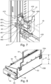
- Fig. 6 there is shown partly a cross-sectional horizontal view from above of a corner of an installation according to the invention, wherein one upright 30 is shown, such that there is also shown a part of the longitudinal frame work 31, a part of one longitudinal platform 5 with bumper 83 and a part of one transversal platform 6.
- the hydraulic piston 42 for movement of the longitudinal platform in a transversal direction, is shown in more detail clearly presenting the two attachment members 43, 44.
- a cross-section of the hollow carrying member 50 which exposes the positioning of the support beam 40 within the hollow space of the hollow carrying member 50. At the end of the support beam 40 it is connected to an anchoring mechanism 41, as mentioned above.
- the anchoring frame 410 has connected thereto a lower (not shown) and an upper shaft 415. At each end of each shaft there are arranged rollers 414, 411 that are guided within U-shaped guide rails 412, 413 attached on each inner side of the upright 30. Accordingly, there are arranged two U-shaped guide rails 412, 413 opposing each other within the upright 30.
- the rollers 411, 414 fit into the U-shaped guide rails to more or less without friction guide each end of the support beam 40 vertically along a desired path.
- connection between the end of the support beam and the anchoring mechanism 41 includes a cardan joint 46 such that bending forces will not be transmitted from the support beams 40 platform to the anchoring mechanism 41, as is explained in more detail in connection with Fig. 7 .
- Fig. 7 there is shown in more detail a perspective view of a exemplary arrangement of the anchoring mechanism 41.
- the cardan joint 46 comprises an inner attachment body 460 that is fixated within the hollow support beam 40.
- a first pivot shaft 461 is mounted with an inner end in the inner attachment body 460 and an outer end in a first pivot member 462. Hence, this facilitates pivoting of the support beam 40 about the axis of the first pivot shaft 461.
- the first pivot member 462 is pivotally arranged about a second pivot shaft 463.
- a limit stop switch 416 that may assist in controlling that the movable structure 4 does not pass by a set end position and also that a bracket 417 for a cable guide 418 may be arranged below the support beam 40.
- Fig. 8 there is shown a perspective view of an end part of a longitudinal platform. It is shown that the hollow carrying member 50 is fixedly attached to an end face plate 54. The end face plate 54 protrudes a distance above the actual platform floor 52. Also the rear wall 53 of the longitudinal platform 5 extends a distance h5 above the floor of the platform 5, as has been described above to both eliminate the risk of tools falling down from the platform and to provide sufficient strength to make the longitudinal platform self-supporting.
- Fig. 9 there is shown a perspective view of a transversal platform 6. It is shown that the transversal platform 6 is arranged with a pair of wheel members 630 at each outer end, which provides for precise guiding of the platform in a longitudinal direction along the rails 55 on the longitudinal platforms 5. Further, it is shown in more detail that there is an intermediate part 60 that may telescopically move into the fixed parts 633, 643 arranged with space for occupying the intermediate part 60 when the transversal platform 6 is telescoping to be shorter . To provide for extra guidance and also eliminate objects to fall down from the floor surface 62 of the platform there are arranged upwardly protruding telescoping wall parts 642, 632. Preferably a first wall part 642 presents a flat plate shape and the other part 632 presenting a bent plate 63 with a U-shaped upper portion that may ride on top of the first wall part 642.
- Fig. 10 there is shown a view from above of a transversal platform 6 according to the invention, wherein the brake mechanism 66, is shown in more detail. It is shown that there is arranged a long telescopic pivot rod 662 that extends along the whole back side of the platform 6 that is pivotally supported by brackets 663.
- the brake gripping member 660 is fixedly attached to the pivot rod 662. At each end of the pivot rod 662 it connects with a movable brake part 664, which at its outer end is arranged with a brake member 665.
- the movable brake part 664 is arranged with a radially protruding shaft device (e.g.
- a perspective view of a stairway 7 that may form a part of the concept according to the invention. It is how that the stairway comprises a lower static part 7A and an upper adjustable part 7B. At the top of the upper part 7B there is a platform 72. The platform 72 may be adjustably positioned on different vertical heights by means of a hydraulic cylinder 70 that can move the upper part 7B from the lowermost position to the uppermost position.
- the stairway 7 includes two stairway uprights 71 that include guiding members for controlled guided movement of the upper part 7B of the stairway 7.
- the upper part includes a stairway portion 73 that includes two parallel attachment members 730, 731 for adapted positioning of each step 732 in the stairway 73 to be positioned horizontally in every position.
- an intermediate platform 74A At the top of the fixed stairway part 7A there is an intermediate platform 74A.
- Fixed stairway part 75 lead to the intermediate platform 74.
- safety fences 728, 748 arranged to provide for safe climbing of the stairway, (in Figs 11-13 the safety fence part along the upper stairway portion 73 is not shown but merely in Fig. 14 ).
- the piston 70 is arranged centrally between the uprights 71 of the stairway 7.
- support legs 76 At the intermediate platform 74 there is arranged support legs 76, preferably in the form of an up and down turned U.
- a guiding arrangement 78 attached to the platform and extending along a side support 79 that is attached underneath the upper platform 72.
- a separate platform (not shown) to have the hydraulic pump/machinery for the stairway positioned at a level above the ground floor GF to provide sufficient space to enable walking underneath it or it may also be positioned together with the other hydraulic devices, e.g. under the fixed platform 74.
- Fig. 12 and 13 there are shown side views of a stairway shown in Fig. 11 wherein it is shown in an upper position in Fig. 12 and in a lower position in Fig. 13 .
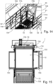
- Fig. 14 there is a perspective view from above showing a part of a workshop 1 in between two installations 2, 2' with focus on the upper part of a stairway 7 according to the invention.
- the upper platform 72 of the stairway is in level with a platform 52 of the closest installation 2 and also a platform 52' of an installation 2' further away.
- telescopic side platforms 720, 721 may be extended to be in contact with each one of the longitudinal platforms 52, 52'. Accordingly, a person may move from the platform 72 via a side platform 720, 721 to enter onto any of the platforms 52, 52'.
- the safety fence 728 around the platform 72 is arranged with two doors 77A, 77B, each one providing opening to one of the side platforms 720, 721. It should be noted that in the shown figure the framework parts 31 have been omitted, such that there is shown a gap in between the upper angled lateral support beams 33 and the rest of the structure.
- Fig. 15 there is shown a cross-sectional view from below of an upper part of a stairway 7 according to the invention.
- a piston part 70 of the hydraulic cylinder that may move the upper platform 72 up and down.
- the side platforms 720, 721 have been extended sideways and that there may be rollers 722 arranged to provide for low friction movement of the side platforms 720, 720.
- each stairway upright 71 is arranged with protruding ruler 710 that acts as a guide element for the upper platform 72, by means of having gripping members 720 that guide along the rulers 710 on both sides.
- the platform may be equipped with a flexible cable support 723.
- chains 730 on each side at the top of the upper the safety fence 728 of the upper platform 72 which chains will extend and form safety fences when the stairway is in its upper position, and which chains in the lower position of the upper platform 72 will merely flex and hang down along each side.
- Fig. 16 there is shown a further possible embodiment of a part of a workshop 1 having two installations 2, 2', arranged in series, i.e. along the same path of passage C, where two vehicles B, B' may be serviced simultaneously according to the invention.
- the installation 2 may advantagely be used in connection with lifters 100, that may lift the vehicle B up into a higher level, such that service may be performed from the underside of the vehicle B.
- service may also be performed on the roof by means of positioning the platforms 5, 6 at an appropriate level for simultaneous service at that level.
- the invention may be combined with using equipment installed below the ground floor level GF , e.g. lifters 100, service pits, etc.
- the figure shows that in some workshops 1 it may be an advantage to use two installations of different length, e.g. a longer one 2' followed by a shorter one 2, such that simultaneously a first vehicle of a first size may be serviced in the front installation and a second vehicle of a shorter kind may be serviced in the rear installation.
- the installation is basically similar to what has been described above.
- the invention is not limited by the examples described above but may be varied within the scope of the appended claims.
- the invention may be used in connection with numerous, various stabilizing structures for the fixed structure.
- the installations use the basic structure as suggested by means of having two parallel longitudinal frame works 31, in order to provide for an easy installation of crane beam 9.
- many different guiding arrangements may be used both for guiding of the vertical anchoring members 41 and for guidance of the transversal platforms in a longitudinal direction and also for the longitudinal platforms for guidance in a transversal direction.
- the stabilizing rear wall 53 of the longitudinal platform 5 may be made in many different materials that can provide sufficient strength and also sufficient hinder for larger objects not to fall outside from the floor 52 of the platform 5.
- different kind of actuating devices other than hydraulic cylinders may be used, e.g. linear actuator, rack and pinion devices, which for instance may be powered by electric motors.
- separate parts of the invention may be the subject for divisional applications, e.g. the configuration of the stairways 7, the arrangement of a self-supporting longitudinal platform, etc.
Landscapes
- Engineering & Computer Science (AREA)
- Structural Engineering (AREA)
- Life Sciences & Earth Sciences (AREA)
- Geology (AREA)
- Mechanical Engineering (AREA)
- Float Valves (AREA)
- Vehicle Step Arrangements And Article Storage (AREA)
- Fittings On The Vehicle Exterior For Carrying Loads, And Devices For Holding Or Mounting Articles (AREA)
- Refuge Islands, Traffic Blockers, Or Guard Fence (AREA)
- Conveying And Assembling Of Building Elements In Situ (AREA)
Claims (15)
- Vorrichtung (2) für einen sicheren Zugang zu einem oberen Teil eines Fahrzeugs (B), wobei die Vorrichtung umfasst:einen befestigten Rahmen (3), der entlang einer Durchgangslinie (C) für das Fahrzeug (B) angeordnet ist, wobei der befestigte Rahmen (3) wenigstens vier, bevorzugt lediglich vier, Ständer (30) umfasst, die an ihren oberen Enden durch sich längs und quer erstreckende Stützstrukturen (31, 35, 32, 36) miteinander verbunden sind,eine vertikal bewegliche Stützstruktur (4), die relativ zu dem befestigten Rahmen (3) beweglich ist, und wobei die vertikal bewegliche Stützstruktur (4) ein Paar von Querstützbalken (40) umfasst, die sich quer zwischen einem Paar der Ständer (30) erstrecken, die auf jeder Seite der Durchgangslinie (C) positioniert sind,wenigstens eine Längsplattform (5), die von der beweglichen Stützstruktur (4) gestützt ist,eine erste Betätigungsvorrichtung (45) mit einem befestigten Teil (450), das relativ zu dem befestigten Rahmen (3) befestigt ist, und einem beweglichen Teil (452), das an der beweglichen Stützstruktur (4) angebracht ist, um eine vertikale Bewegung der beweglichen Stützstruktur (4) zu ermöglichen, wobeiangrenzend an jedes Ende der Querstützbalken (40) eine bewegliche Verankerungsvorrichtung (41) angeordnet ist, die durch die Ständer (30) geführt ist, um eine vertikale Bewegung, aber in anderen Richtungen eine feste Positionierung zu ermöglichen,gekennzeichnet durch eine zweite Betätigungsvorrichtung (42), die ein Teil (420) aufweist, das an einem ersten Befestigungselement (44) angebracht ist, das an der beweglichen Stützstruktur (4) befestigt ist, und ein anderes Teil (421), das an einem zweiten Befestigungselement (43) angebracht ist, das an der Längsplattform (5) angebracht ist, um eine horizontale Bewegung der Längsplattform (5) auf den Stützbalken (40) zu ermöglichen.
- Vorrichtung (2) nach Anspruch 1, dadurch gekennzeichnet, dass wenigstens eine in einer Längsrichtung bewegliche Querplattform (6) angeordnet ist, wobei bevorzugt wenigstens ein Ende von der Längsplattform (5) beweglich gestützt ist.
- Vorrichtung (2) nach Anspruch 2, dadurch gekennzeichnet, dass ein Paar parallel angeordneter Längsplattformen (5) vorhanden ist, wobei bevorzugt zwei Querplattformen (6) vorhanden sind, die an jedem Ende beweglich von dem Paar Längsplattformen (5) gestützt ist.
- Vorrichtung (2) nach einem der Ansprüche 1 bis 3, dadurch gekennzeichnet, dass die Stützstrukturen (31, 35, 32, 36) wenigstens ein längs verlaufendes Rahmenelement (31, 35), bevorzugt zwei parallele längs verlaufende Rahmenelemente (31, 35), umfassen.
- Vorrichtung (2) nach Anspruch 4, dadurch gekennzeichnet, dass die Stützstrukturen (31, 35, 32, 36) wenigstens ein Querrahmenelement (32, 36), bevorzugt zwei Querrahmenelemente (32, 36), umfassen.
- Vorrichtung (2) nach einem der Ansprüche 2-3, dadurch gekennzeichnet, dass die Querplattform/en (6) zwei Teile (6A, 6B) umfasst/en, die teleskopartig zusammenwirken.
- Vorrichtung (2) nach einem der Ansprüche 1-6, dadurch gekennzeichnet, dass die Längsplattform (5) einen Boden (52) aufweist, der entlang einer äußeren Längsseite durch eine Stützwand (53) begrenzt ist, wobei die Stützwand (53) dazu angeordnet ist, für Festigkeit zu sorgen und auch zu verhindern, dass Gegenstände von dem Boden (52) herunterfallen, indem die Stützwand (53) eine beträchtliche Höhe (h5) aufweist und die Stützwand (53) so befestigt ist, dass ihre Unterkante (53B) auf oder unter dem Niveau des Bodens (52) liegt und ihre Oberkante (53A) deutlich über dem Niveau des Bodens (52) liegt.
- Vorrichtung (2) nach Anspruch 7, dadurch gekennzeichnet, dass die Höhe (h5) wenigstens 250 mm beträgt, bevorzugt im Bereich von 300 bis 1000 liegt, und mehr bevorzugt, dass die Höhe (h5) in der Mitte zwischen den kurzen Endwänden (54) der Plattform (5) größer ist als angrenzend an die kurzen Endwände der Plattform.
- Vorrichtung (2) nach einem der Ansprüche 1 bis 8, dadurch gekennzeichnet, dass die Längsplattform (5) kurze Endwände (54) aufweist und an jeder kurzen Endwand (54) ein hohles Trägerelement (50) angebracht ist, wobei die hohlen Trägerelemente (50) eine Stütze und einen quer verlaufenden offenen Raum zur Aufnahme der Stützbalken (40) bereitstellen, um eine Querbewegung der Längsplattform (5) zu ermöglichen.
- Vorrichtung (2) nach Anspruch 9, dadurch gekennzeichnet, dass an dem hohlen Stützelement (50), bevorzugt an seiner Außenseite, das zweite Befestigungselement (43) angebracht ist, wobei bevorzugt das erste Befestigungselement (44) an dem Stützbalken (40) angebracht ist.
- Vorrichtung (2) nach einem der Ansprüche 4 bis 10, dadurch gekennzeichnet, dass ein Paar paralleler Längsrahmenelemente (31, 31'), entweder in einer Vorrichtung (2) oder in zwei parallelen benachbarten Vorrichtungn (2, 2'), einen quer angeordneten Kranbalken (9) stützen, der dazu angeordnet ist, in Längsrichtung beweglich zu sein.
- Vorrichtung (2) nach einem der Ansprüche 1 bis 11, wobei eine erste Betätigungsvorrichtung (45) an der beweglichen Verankerungsvorrichtung (41) angebracht ist, wobei bevorzugt die bewegliche Verankerungsvorrichtung (41) einen Verankerungsrahmen (410) umfasst.
- Vorrichtung (2) nach Anspruch 12, dadurch gekennzeichnet, dass die bewegliche Verankerungsvorrichtung (41) mit dem Stützbalken (40) über ein Kardangelenk (46) verbunden ist, bevorzugt angrenzend an oder an jedem Ende (40A) jedes Stützbalkens (40) und an einem Führungsrahmenelement (410).
- Vorrichtung (2) nach einem der Ansprüche 1 bis 13, dadurch gekennzeichnet, dass sie wenigstens eine Treppenanordnung (7) mit einem unteren festen Treppenteil (7A) und einem oberen beweglichen Treppenteil (7B) umfasst, der eine obere Plattform (72) umfasst, die mittels einer Betätigungsvorrichtung (70) auf verschiedenen Ebenen positioniert werden kann.
- Vorrichtung (2) nach Anspruch 14, dadurch gekennzeichnet, dass die obere Plattform (72) wenigstens eine, bevorzugt zwei, teleskopische Seitenplattform/en (720, 721) umfasst, die dazu angeordnet ist/sind, einen erweiterten Boden an einer Seite oder an beiden Seiten der oberen Plattform (72) bereitzustellen.
Applications Claiming Priority (2)
| Application Number | Priority Date | Filing Date | Title |
|---|---|---|---|
| SE2150411A SE544679C2 (en) | 2021-03-31 | 2021-03-31 | Installation for secure access to an upper part of a vehicle |
| PCT/EP2022/056794 WO2022207318A1 (en) | 2021-03-31 | 2022-03-16 | Installation for secure access to an upper part of a vehicle |
Publications (3)
| Publication Number | Publication Date |
|---|---|
| EP4313841A1 EP4313841A1 (de) | 2024-02-07 |
| EP4313841C0 EP4313841C0 (de) | 2025-04-16 |
| EP4313841B1 true EP4313841B1 (de) | 2025-04-16 |
Family
ID=81325572
Family Applications (1)
| Application Number | Title | Priority Date | Filing Date |
|---|---|---|---|
| EP22715072.9A Active EP4313841B1 (de) | 2021-03-31 | 2022-03-16 | Anlage für sicheren zugang zu einem oberen teil eines fahrzeugs |
Country Status (3)
| Country | Link |
|---|---|
| EP (1) | EP4313841B1 (de) |
| SE (1) | SE544679C2 (de) |
| WO (1) | WO2022207318A1 (de) |
Families Citing this family (1)
| Publication number | Priority date | Publication date | Assignee | Title |
|---|---|---|---|---|
| EP4671192A1 (de) * | 2024-06-24 | 2025-12-31 | OTech GmbH | Fertigungsanlage |
Family Cites Families (10)
| Publication number | Priority date | Publication date | Assignee | Title |
|---|---|---|---|---|
| US4776429A (en) * | 1987-06-01 | 1988-10-11 | Osborn Vernon E | Loading and inspection platform |
| US5685392A (en) * | 1994-11-03 | 1997-11-11 | Vertex Systems Group, Inc. | Multiple lift platform with lateral movement |
| SE522680C2 (sv) * | 2000-01-27 | 2004-02-24 | Scania Cv Ab | Plattformsarrangemang |
| ITFI20010096U1 (it) * | 2001-12-04 | 2003-06-04 | Ricci Francesco | Piattaforma mobile plurifunzionale per la manutenzione di carrozze ferroviarie ed elementi rotabili in genere |
| DE202004011076U1 (de) * | 2004-07-15 | 2004-11-25 | Neuero Technology Gmbh | Arbeitsbühne für Schienenfahrzeuge |
| CA2633824C (en) * | 2008-05-28 | 2009-04-28 | Faham Hanif | Movable platform apparatus for accessing large vehicles |
| FR2957044B1 (fr) * | 2010-03-04 | 2012-03-30 | Techni Metal Systemes | Atelier de maintenance de rames de transport ferroviaire |
| FR2996542B1 (fr) | 2012-10-08 | 2015-04-03 | Tecmeca Pacquet | Installation d'acces securise a une partie superieure d'un vehicule |
| CN202866341U (zh) | 2012-10-31 | 2013-04-10 | 江西凯马百路佳客车有限公司 | 龙门式太阳能辅助能源客车顶棚维修清扫装置 |
| ES2627789B1 (es) * | 2016-01-29 | 2018-05-21 | Transports De Barcelona, S.A. | Conjunto de plataforma móvil para el acceso a vehículos de grandes dimensiones con fines de inspección y mantenimiento, método y programa de ordenador para controlar al conjunto |
-
2021
- 2021-03-31 SE SE2150411A patent/SE544679C2/en unknown
-
2022
- 2022-03-16 WO PCT/EP2022/056794 patent/WO2022207318A1/en not_active Ceased
- 2022-03-16 EP EP22715072.9A patent/EP4313841B1/de active Active
Also Published As
| Publication number | Publication date |
|---|---|
| EP4313841A1 (de) | 2024-02-07 |
| WO2022207318A1 (en) | 2022-10-06 |
| SE2150411A1 (en) | 2022-10-01 |
| SE544679C2 (en) | 2022-10-11 |
| EP4313841C0 (de) | 2025-04-16 |
Similar Documents
| Publication | Publication Date | Title |
|---|---|---|
| ES2968201T3 (es) | Accionamiento de elevación para un sistema trepador guiado por carriles y procedimiento para el trepado de un sistema trepador guiado por carriles | |
| EP3368730B1 (de) | Kletterausrüstung zum bau von gebäuden | |
| US5645395A (en) | Building crane apparatus climbable on building walls | |
| AU2013201212A1 (en) | Motorized height access device for tower cranes | |
| US20090173574A1 (en) | Guide shoe and climbing system for use in the building sector | |
| US20190194957A1 (en) | Telescoping Break-Away Canopy Assembly | |
| CN112777455B (zh) | 电梯轿厢 | |
| EP1723066B1 (de) | Aufzugssystem | |
| EP1509473B1 (de) | Sicherheitsumzäunung auf aufzugskabine | |
| CN210561776U (zh) | 一种桥梁防撞护栏外挂平台 | |
| KR20140082972A (ko) | 승강기 | |
| CA2834094C (en) | Self-contained, portable and self-supporting scaffolding kit | |
| EP4313841B1 (de) | Anlage für sicheren zugang zu einem oberen teil eines fahrzeugs | |
| US20050230194A1 (en) | Safety fence at upper part of cab | |
| US20090071751A1 (en) | Portable aerial platform | |
| JPH0530758B2 (de) | ||
| WO2003002447A1 (en) | Lift especially for mounting on a substantially vertical building and security arrangement for said lift | |
| NL2007349C2 (nl) | Transportinrichting en -systeem, alsmede werkwijze voor de toepassing daarvan. | |
| RU210356U1 (ru) | Площадка передвижная с лестницей для входа в кабину машиниста и обслуживания подвижного состава | |
| CN214059798U (zh) | 一种电梯安装辅助装置 | |
| US20250237072A1 (en) | Telescopic climbing scaffold | |
| US20260085529A1 (en) | Deck for use in construction | |
| SU883293A1 (ru) | Опорно-ходовое устройство дл передвижных лесов | |
| ITBO20090185A1 (it) | Piattaforma transelevatrice per interventi di manutenzione sull'imperiale di locomotori posti su due binari affiancati, uno dei quali puo' rimanere elettricamente servito. | |
| NL2023549B1 (nl) | Werkwijze voor het bouwen van een voor personen toegankelijk gebouw |
Legal Events
| Date | Code | Title | Description |
|---|---|---|---|
| STAA | Information on the status of an ep patent application or granted ep patent |
Free format text: STATUS: UNKNOWN |
|
| STAA | Information on the status of an ep patent application or granted ep patent |
Free format text: STATUS: THE INTERNATIONAL PUBLICATION HAS BEEN MADE |
|
| PUAI | Public reference made under article 153(3) epc to a published international application that has entered the european phase |
Free format text: ORIGINAL CODE: 0009012 |
|
| STAA | Information on the status of an ep patent application or granted ep patent |
Free format text: STATUS: REQUEST FOR EXAMINATION WAS MADE |
|
| 17P | Request for examination filed |
Effective date: 20230707 |
|
| AK | Designated contracting states |
Kind code of ref document: A1 Designated state(s): AL AT BE BG CH CY CZ DE DK EE ES FI FR GB GR HR HU IE IS IT LI LT LU LV MC MK MT NL NO PL PT RO RS SE SI SK SM TR |
|
| DAV | Request for validation of the european patent (deleted) | ||
| DAX | Request for extension of the european patent (deleted) | ||
| GRAP | Despatch of communication of intention to grant a patent |
Free format text: ORIGINAL CODE: EPIDOSNIGR1 |
|
| STAA | Information on the status of an ep patent application or granted ep patent |
Free format text: STATUS: GRANT OF PATENT IS INTENDED |
|
| INTG | Intention to grant announced |
Effective date: 20241218 |
|
| GRAS | Grant fee paid |
Free format text: ORIGINAL CODE: EPIDOSNIGR3 |
|
| GRAA | (expected) grant |
Free format text: ORIGINAL CODE: 0009210 |
|
| STAA | Information on the status of an ep patent application or granted ep patent |
Free format text: STATUS: THE PATENT HAS BEEN GRANTED |
|
| AK | Designated contracting states |
Kind code of ref document: B1 Designated state(s): AL AT BE BG CH CY CZ DE DK EE ES FI FR GB GR HR HU IE IS IT LI LT LU LV MC MK MT NL NO PL PT RO RS SE SI SK SM TR |
|
| REG | Reference to a national code |
Ref country code: GB Ref legal event code: FG4D |
|
| REG | Reference to a national code |
Ref country code: CH Ref legal event code: EP |
|
| REG | Reference to a national code |
Ref country code: IE Ref legal event code: FG4D |
|
| REG | Reference to a national code |
Ref country code: DE Ref legal event code: R096 Ref document number: 602022013247 Country of ref document: DE |
|
| U01 | Request for unitary effect filed |
Effective date: 20250429 |
|
| U07 | Unitary effect registered |
Designated state(s): AT BE BG DE DK EE FI FR IT LT LU LV MT NL PT RO SE SI Effective date: 20250507 |
|
| PG25 | Lapsed in a contracting state [announced via postgrant information from national office to epo] |
Ref country code: ES Free format text: LAPSE BECAUSE OF FAILURE TO SUBMIT A TRANSLATION OF THE DESCRIPTION OR TO PAY THE FEE WITHIN THE PRESCRIBED TIME-LIMIT Effective date: 20250416 |
|
| PG25 | Lapsed in a contracting state [announced via postgrant information from national office to epo] |
Ref country code: GR Free format text: LAPSE BECAUSE OF FAILURE TO SUBMIT A TRANSLATION OF THE DESCRIPTION OR TO PAY THE FEE WITHIN THE PRESCRIBED TIME-LIMIT Effective date: 20250717 Ref country code: NO Free format text: LAPSE BECAUSE OF FAILURE TO SUBMIT A TRANSLATION OF THE DESCRIPTION OR TO PAY THE FEE WITHIN THE PRESCRIBED TIME-LIMIT Effective date: 20250716 |
|
| PG25 | Lapsed in a contracting state [announced via postgrant information from national office to epo] |
Ref country code: PL Free format text: LAPSE BECAUSE OF FAILURE TO SUBMIT A TRANSLATION OF THE DESCRIPTION OR TO PAY THE FEE WITHIN THE PRESCRIBED TIME-LIMIT Effective date: 20250416 |
|
| PG25 | Lapsed in a contracting state [announced via postgrant information from national office to epo] |
Ref country code: HR Free format text: LAPSE BECAUSE OF FAILURE TO SUBMIT A TRANSLATION OF THE DESCRIPTION OR TO PAY THE FEE WITHIN THE PRESCRIBED TIME-LIMIT Effective date: 20250416 |
|
| PG25 | Lapsed in a contracting state [announced via postgrant information from national office to epo] |
Ref country code: RS Free format text: LAPSE BECAUSE OF FAILURE TO SUBMIT A TRANSLATION OF THE DESCRIPTION OR TO PAY THE FEE WITHIN THE PRESCRIBED TIME-LIMIT Effective date: 20250716 |
|
| PG25 | Lapsed in a contracting state [announced via postgrant information from national office to epo] |
Ref country code: IS Free format text: LAPSE BECAUSE OF FAILURE TO SUBMIT A TRANSLATION OF THE DESCRIPTION OR TO PAY THE FEE WITHIN THE PRESCRIBED TIME-LIMIT Effective date: 20250816 |
|
| PG25 | Lapsed in a contracting state [announced via postgrant information from national office to epo] |
Ref country code: SM Free format text: LAPSE BECAUSE OF FAILURE TO SUBMIT A TRANSLATION OF THE DESCRIPTION OR TO PAY THE FEE WITHIN THE PRESCRIBED TIME-LIMIT Effective date: 20250416 |
|
| PG25 | Lapsed in a contracting state [announced via postgrant information from national office to epo] |
Ref country code: CZ Free format text: LAPSE BECAUSE OF FAILURE TO SUBMIT A TRANSLATION OF THE DESCRIPTION OR TO PAY THE FEE WITHIN THE PRESCRIBED TIME-LIMIT Effective date: 20250416 |
|
| PG25 | Lapsed in a contracting state [announced via postgrant information from national office to epo] |
Ref country code: SK Free format text: LAPSE BECAUSE OF FAILURE TO SUBMIT A TRANSLATION OF THE DESCRIPTION OR TO PAY THE FEE WITHIN THE PRESCRIBED TIME-LIMIT Effective date: 20250416 |
|
| PLBE | No opposition filed within time limit |
Free format text: ORIGINAL CODE: 0009261 |
|
| STAA | Information on the status of an ep patent application or granted ep patent |
Free format text: STATUS: NO OPPOSITION FILED WITHIN TIME LIMIT |
|
| REG | Reference to a national code |
Ref country code: CH Ref legal event code: L10 Free format text: ST27 STATUS EVENT CODE: U-0-0-L10-L00 (AS PROVIDED BY THE NATIONAL OFFICE) Effective date: 20260225 |
|
| 26N | No opposition filed |
Effective date: 20260119 |