EP4309976B1 - Lenksteuerungssystem und lenksteuerungsverfahren - Google Patents
Lenksteuerungssystem und lenksteuerungsverfahren Download PDFInfo
- Publication number
- EP4309976B1 EP4309976B1 EP23186285.5A EP23186285A EP4309976B1 EP 4309976 B1 EP4309976 B1 EP 4309976B1 EP 23186285 A EP23186285 A EP 23186285A EP 4309976 B1 EP4309976 B1 EP 4309976B1
- Authority
- EP
- European Patent Office
- Prior art keywords
- steering
- correction information
- turning
- state
- angle
- Prior art date
- Legal status (The legal status is an assumption and is not a legal conclusion. Google has not performed a legal analysis and makes no representation as to the accuracy of the status listed.)
- Active
Links
Images


Classifications
-
- B—PERFORMING OPERATIONS; TRANSPORTING
- B62—LAND VEHICLES FOR TRAVELLING OTHERWISE THAN ON RAILS
- B62D—MOTOR VEHICLES; TRAILERS
- B62D15/00—Steering not otherwise provided for
- B62D15/02—Steering position indicators ; Steering position determination; Steering aids
-
- B—PERFORMING OPERATIONS; TRANSPORTING
- B62—LAND VEHICLES FOR TRAVELLING OTHERWISE THAN ON RAILS
- B62D—MOTOR VEHICLES; TRAILERS
- B62D15/00—Steering not otherwise provided for
- B62D15/02—Steering position indicators ; Steering position determination; Steering aids
- B62D15/021—Determination of steering angle
-
- B—PERFORMING OPERATIONS; TRANSPORTING
- B62—LAND VEHICLES FOR TRAVELLING OTHERWISE THAN ON RAILS
- B62D—MOTOR VEHICLES; TRAILERS
- B62D5/00—Power-assisted or power-driven steering
- B62D5/04—Power-assisted or power-driven steering electrical, e.g. using an electric servo-motor connected to, or forming part of, the steering gear
- B62D5/0457—Power-assisted or power-driven steering electrical, e.g. using an electric servo-motor connected to, or forming part of, the steering gear characterised by control features of the drive means as such
- B62D5/046—Controlling the motor
- B62D5/0463—Controlling the motor calculating assisting torque from the motor based on driver input
-
- B—PERFORMING OPERATIONS; TRANSPORTING
- B62—LAND VEHICLES FOR TRAVELLING OTHERWISE THAN ON RAILS
- B62D—MOTOR VEHICLES; TRAILERS
- B62D6/00—Arrangements for automatically controlling steering depending on driving conditions sensed and responded to, e.g. control circuits
-
- B—PERFORMING OPERATIONS; TRANSPORTING
- B62—LAND VEHICLES FOR TRAVELLING OTHERWISE THAN ON RAILS
- B62D—MOTOR VEHICLES; TRAILERS
- B62D15/00—Steering not otherwise provided for
- B62D15/02—Steering position indicators ; Steering position determination; Steering aids
- B62D15/021—Determination of steering angle
- B62D15/0245—Means or methods for determination of the central position of the steering system, e.g. straight ahead position
-
- B—PERFORMING OPERATIONS; TRANSPORTING
- B62—LAND VEHICLES FOR TRAVELLING OTHERWISE THAN ON RAILS
- B62D—MOTOR VEHICLES; TRAILERS
- B62D5/00—Power-assisted or power-driven steering
- B62D5/04—Power-assisted or power-driven steering electrical, e.g. using an electric servo-motor connected to, or forming part of, the steering gear
- B62D5/0457—Power-assisted or power-driven steering electrical, e.g. using an electric servo-motor connected to, or forming part of, the steering gear characterised by control features of the drive means as such
- B62D5/0481—Power-assisted or power-driven steering electrical, e.g. using an electric servo-motor connected to, or forming part of, the steering gear characterised by control features of the drive means as such monitoring the steering system, e.g. failures
Definitions
- the present invention relates to a steering control system and a steering control method.
- JP 2021-195086 A also published as EP 3 935 863 A1 , describes a steer-by-wire steering device that is installed in a vehicle.
- the steer-by-wire steering device has a structure in which a power transmission path between a steering wheel of the vehicle and turning wheels of the vehicle is cut off.
- Such a steer-by-wire steering device includes a steering control system that controls the steering device as a target.
- steering angle midpoint information that serves as a reference when calculating a steering angle of the steering wheel to be used for control is stored in a memory.
- the steering angle midpoint information having been stored in the memory can disappear, for example, when a battery is removed from the vehicle.
- the steering control system is configured to execute a process for storing the steering angle midpoint information in the memory once again when the steering angle midpoint information has disappeared.
- an abnormality in the memory can occur, for example, due to an abnormality in writing into the memory or to writing of steering angle midpoint information that is abnormal in the first place.
- an abnormality in the memory occurs, the steering angle of the steering wheel to be used for control will be obtained with reference only to abnormal steering angle midpoint information. This leads to deviation from an actual state of the steering device.
- a steering control system controls a steering device of a vehicle.
- the steering device has a structure in which a power transmission path between a steering unit having an operation member and a turning unit configured to turn turning wheels is cut off.
- the steering control system has a storage unit that stores information relating to control of the steering device, and a control unit configured to make a state transition to a normal control state via a start-up state after a power source system of the vehicle is started.
- the start-up state is a state where the control unit executes a correction information storing process of acquiring correction element information using a state variable obtained from the steering device and further writing correction information obtained based on the acquired correction element information into the storage unit.
- the normal control state is a state where the control unit executes a normal process of controlling the steering device using a control variable that is obtained by correcting the state variable based on the correction information.
- the control unit is configured to execute, in the start-up state, an abnormal condition determination process of determining whether an abnormal condition indicating that the correction information having been written into the storage unit through the correction information storing process is abnormal is met.
- the correction information storing process is a process that is re-executed when the abnormal condition is met.
- the abnormal condition determination process is a process that is executed at least either before or after the correction information storing process.
- a steering control method is a method of controlling a steering device of a vehicle.
- the steering device has a structure in which a power transmission path between a steering unit having an operation member and a turning unit configured to turn turning wheels is cut off.
- the steering control method includes storing information relating to control of the steering device, and making a state transition to a normal control state via a start-up state after a power source system of the vehicle is started.
- the start-up state is a state where a correction information storing process is executed, the correction information storing process acquires correction element information using a state variable obtained from the steering device and further stores correction information obtained based on the acquired correction element information.
- the normal control state is a state where a normal process is executed, the normal process controls the steering device using a control variable that is obtained by correcting the state variable based on the correction information.
- the method includes executing, in the start-up state, an abnormal condition determination process of determining whether an abnormal condition indicating that the correction information having been stored through the correction information storing process is abnormal is met.
- the correction information storing process is a process that is re-executed when the abnormal condition is met.
- the abnormal condition determination process is a process that is executed at least either before or after the correction information storing process.
- the control unit can use the correct correction information by re-executing the correction information storing process.
- the control unit can create a situation where the state variable can be corrected based on the correction information. Therefore, the control variable is less likely to deviate from the actual state of the steering device.
- control unit may be configured to execute, in the start-up state, an abnormality information storing process of writing abnormal condition information into the storage unit when writing of the correction information into the storage unit has failed to be completed.
- the abnormal condition determination process may be a process that is executed before the correction information storing process, and may include a process of determining that the abnormal condition is met when the abnormal condition information has been written in the storage unit.
- the control unit can correct the state variable based on the correct correction information.
- control unit may be configured to execute, in the start-up state, a battery replacement condition determination process of determining whether a battery replacement condition indicating a state after a battery belonging to the power source system of the vehicle has been removed and replaced is met.
- the correction information storing process may be a process that is executed when the battery replacement condition is met and may be a process that is not executed when the battery replacement condition is not met.
- the abnormal condition determination process may be a process that is executed before the battery replacement condition determination process.
- the control unit can appropriately respond to an abnormality in the storage unit relating to the correction information having been written into the storage unit through the correction information storing process.
- the reliability of the accuracy of the correction information can be increased.
- the steering device may include a sensor that detects an actually measured value corresponding to the control variable obtained by correction based on the correction information.
- the abnormal condition determination process may be a process that is executed after the correction information storing process, and may include a process of determining whether the abnormal condition is met based on a result of comparing the control variable obtained by correction based on the correction information and the actually measured value obtained from the sensor.
- the control unit can correct the state variable based on the correct correction information.
- the correction information may include steering-side correction information and turning-side correction information.
- the steering-side correction information may be information for correcting a control variable for steering that is used when controlling the steering unit
- the turning-side correction information may be information for correcting a control variable for turning that is used when controlling the turning unit.
- the correction information storing process may include a steering-side correction information storing process and a turning-side correction information storing process.
- the steering-side correction information storing process may be a process of acquiring steering-side correction element information using a state variable obtained from the steering unit and further writing the steering-side correction information obtained based on the acquired steering-side correction element information into the storage unit.
- the turning-side correction information storing process may be a process of acquiring turning-side correction element information using a state variable obtained from the turning unit and further writing the turning-side correction information obtained based on the acquired turning-side correction element information into the storage unit.
- the abnormal condition determination process may include a process of determining whether an abnormal condition indicating that the steering-side correction information having been written into the storage unit through the steering-side correction information storing process is abnormal is met, and a process of determining whether an abnormal condition indicating that the turning-side correction information having been written into the storage unit through the turning-side correction information storing process is abnormal is met.
- the steering control system can correct the state variables relating respectively to the steering unit and the turning unit. Therefore, the control variables used to respectively control the steering unit and the turning unit are less likely to deviate from the actual states of the respective units.
- the present invention can reduce the likelihood of deviation from the actual state of the steering device.
- a steering control device 1 controls a steering device 2 as a target.
- the steering device 2 is configured as a steer-by-wire vehicle steering device.
- the steering device 2 includes a steering unit 4 and a turning unit 6.
- the steering unit 4 is steered by a driver through a steering wheel 3 of the vehicle that is an operation member.
- the turning unit 6 turns left and right turning wheels 5 of the vehicle according to steering input into the steering unit 4 by the driver.
- the steering device 2 of this embodiment has, for example, a structure in which a power transmission path between the steering unit 4 and the turning unit 6 is always mechanically cut off. In this structure, a power transmission path between a steering actuator 12, to be described later, and a turning actuator 31, to be described later, is always mechanically cut off.
- the steering unit 4 includes a steering shaft 11 and the steering actuator 12.
- the steering shaft 11 is coupled to the steering wheel 3.
- An end portion 11a of the steering shaft 11 on the opposite side from the side coupled to the steering wheel 3 has a stopper mechanism 11b.
- the stopper mechanism 11b defines a rotation range of the steering shaft 11.
- a rotation range of the steering wheel 3 that rotates integrally with the steering shaft 11 is defined by the stopper mechanism 11b.
- the steering wheel 3 can rotate between a rightward rotation limit position 3a and a leftward rotation limit position 3b as the rotation range.
- the steering actuator 12 has a steering-side motor 13 that is a driving source, and a steering-side speed reduction mechanism 14.
- the steering-side motor 13 is a reaction force motor that applies a steering reaction force, which is a force acting against steering, to the steering wheel 3 through the steering shaft 11.
- the steering-side motor 13 is coupled to the steering shaft 11 through the steering-side speed reduction mechanism 14 that is formed by, for example, a worm and wheel.
- the steering-side motor 13 of this embodiment for example, a three-phase brushless motor is adopted.
- the turning unit 6 includes a pinion shaft 21, a rack shaft 22 as a turning shaft, and a rack housing 23.
- the pinion shaft 21 and the rack shaft 22 are coupled together at a predetermined intersection angle.
- Pinion teeth 21a formed on the pinion shaft 21 and rack teeth 22a formed on the rack shaft 22 are meshed with each other to form a rack-and-pinion mechanism 24.
- the pinion shaft 21 corresponds to a rotating shaft of which the angle can be converted into a turning angle ⁇ i that is a turning position of the turning wheels 5.
- the rack housing 23 houses the rack-and-pinion mechanism 24.
- One end of the pinion shaft 21 on the opposite side from the side coupled to the rack shaft 22 protrudes from the rack housing 23.
- the reason for providing the pinion shaft 21 is to support the rack shaft 22 inside the rack housing 23 along with the pinion shaft 21.
- a support mechanism (not shown) provided in the steering device 2
- the rack shaft 22 is supported so as to be movable along its axial direction as well as is pressed toward the pinion shaft 21.
- the rack shaft 22 is supported inside the rack housing 23.
- another support mechanism that supports the rack shaft 22 in the rack housing 23 without using the pinion shaft 21 may be provided.
- the steering-side motor 13 and the turning-side motor 32 are connected to the steering control device 1.
- the steering control device 1 controls operation of the steering-side motor 13 and the turning-side motor 32.
- Detection results of various sensors are input into the steering control device 1.
- the various sensors are connected to the steering control device 1.
- the various sensors include, for example, a torque sensor 41, a steering-side rotation angle sensor 42, a turning-side rotation angle sensor 43, a vehicle speed sensor 44, and a pinion absolute angle sensor 45.
- the torque sensor 41 detects the steering torque Th that is a value indicating a torque having been applied to the steering shaft 11 by the driver's steering operation.
- the steering-side rotation angle sensor 42 detects a rotation angle ⁇ a that is an angle of a rotating shaft of the steering-side motor 13 within a range of 360°.
- the turning-side rotation angle sensor 43 detects a rotation angle ⁇ b that is an angle of a rotating shaft of the turning-side motor 32 within a range of 360°.
- the vehicle speed sensor 44 detects a vehicle speed V that is a travel speed of the vehicle.
- the pinion absolute angle sensor 45 detects a pinion absolute rotation angle ⁇ abp that is an actually measured value of the angle of a rotational axis of the pinion shaft 21 within a range exceeding 360°.
- the torque sensor 41 is provided on the steering shaft 11, at a part closer to the steering wheel 3 than the steering-side speed reduction mechanism 14 is.
- the torque sensor 41 detects the steering torque Th based on twisting of a torsion bar 41a that is provided at an intermediate portion of the steering shaft 11.
- the steering torque Th is detected, for example, as a positive value when the vehicle is steered rightward and as a negative value when the vehicle is steered leftward.
- the steering-side rotation angle sensor 42 is provided in the steering-side motor 13.
- the rotation angle ⁇ a of the steering-side motor 13 is used to calculate a steering angle ⁇ s.
- the steering-side motor 13 and the steering shaft 11 operate in conjunction with each other through the steering-side speed reduction mechanism 14.
- there is a correlation between the rotation angle ⁇ a of the steering-side motor 13 and the steering angle ⁇ s that is a rotation angle indicating the rotational position of the steering wheel 3. Therefore, the steering angle ⁇ s can be calculated based on the rotation angle ⁇ a of the steering-side motor 13.
- the rotation angle ⁇ a is detected, for example, as a positive value when the vehicle is steered rightward and as a negative value when the vehicle is steered leftward.
- the turning-side rotation angle sensor 43 is provided in the turning-side motor 32.
- the rotation angle ⁇ b of the turning-side motor 32 is used to calculate a pinion angle ⁇ p.
- the turning-side motor 32 and the pinion shaft 21 operate in conjunction with each other through the transmission mechanism 33, the conversion mechanism 34, and the rack-and-pinion mechanism 24.
- the pinion angle ⁇ p can be obtained based on the rotation angle ⁇ b of the turning-side motor 32.
- the pinion shaft 21 is meshed with the rack shaft 22.
- the pinion angle ⁇ p is angle information indicating the turning state of the turning wheels 5 and is a value reflecting the turning angle ⁇ i that is the turning position of the turning wheels 5.
- the rotation angle ⁇ b is detected, for example, as a positive value when the vehicle is steered rightward and as a negative value when the vehicle is steered leftward.
- the pinion absolute angle sensor 45 is provided on the pinion shaft 21.
- the pinion absolute rotation angle ⁇ abp of the pinion shaft 21 is used to calculate the pinion angle ⁇ p.
- the pinion absolute rotation angle ⁇ abp is detected, for example, as a positive value when the vehicle is steered rightward and as a negative value when the vehicle is steered leftward.
- the pinion absolute angle sensor 45 is an example of the sensor that detects an actually measured value of the pinion angle ⁇ p.
- a power source system 46 is connected to the steering control device 1.
- the power source system 46 has a battery 47.
- the battery 47 is a secondary battery installed in the vehicle, and serves as an electric power source of electric power that is supplied for the steering-side motor 13 and the turning-side motor 32 to operate. Further, the battery 47 serves as an electric power source of electric power that is supplied for the steering control device 1 to operate.
- a start switch 48 (“SW" in FIG. 1 ) of the vehicle, such as an ignition switch, is provided between the steering control device 1 and the battery 47.
- the start switch 48 is provided at an intermediate point of the power supply line L2 that branches off from the power supply line L1.
- the start switch 48 is operated when starting various functions to operate a travel driving source of the vehicle, such as an engine, and allow the vehicle to operate. Conduction of the power supply line L2 is turned on and off through operation of the start switch 48.
- the operation state of the steering device 2 is linked to the operation state of the vehicle.
- conduction of the power supply line L1 is basically always on, and is indirectly turned on and off as a function of the steering device 2 according to the operation state of the steering device 2.
- the operation state of the steering device 2 is linked to on and off states of conduction of the power supply lines L1, L2 that are supply states of electric power of the battery 47.
- the steering control device 1 includes a central processing unit (hereinafter referred to as a "CPU") 49a and a memory 49b.
- the steering control device 1 executes various processes as the CPU 49a executes programs stored in the memory 49b on a predetermined arithmetic operation cycle.
- the CPU 49a and the memory 49b constitute a microcomputer that is a processing circuit.
- the memory 49b includes computer-readable media, such as a random-access memory (RAM) and a read-only memory (ROM).
- RAM random-access memory
- ROM read-only memory
- the processing circuit belonging to the steering control device 1 may be configured such that at least some of the processes are realized by a hardware circuit, such as a logic circuit.
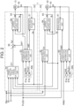
- FIG. 2 shows some of the processes executed by the steering control device 1.
- the processes shown in FIG. 2 are some of the processes that are realized as the CPU 49a executes programs stored in the memory 49b, and these processes are depicted according to the kind of process to be realized.
- the steering control device 1 has a steering-side control unit 50 and a turning-side control unit 60.
- the steering-side control unit 50 controls power supply to the steering-side motor 13.
- the steering-side control unit 50 has a steering-side current sensor 55.
- the steering-side current sensor 55 detects a steering-side actual current value Ia that is obtained from a value of a current in each phase of the steering-side motor 13 that flows through a connection line between the steering-side control unit 50 and a motor coil in each phase of the steering-side motor 13.
- the steering-side current sensor 55 acquires, as a current, a voltage drop of a shunt resistor that is connected to a source side of each switching element in an inverter (not shown) that is provided so as to correspond to the steering-side motor 13.
- connection lines in the respective phases and the current sensors in the respective phases are collectively shown as one connection line and one current sensor.
- the steering-side control unit 50 is one example of the control unit that controls the steering device 2 through control of the operation of the steering-side motor 13.
- the turning-side control unit 60 controls power supply to the turning-side motor 32.
- the turning-side control unit 60 has a turning-side current sensor 65.
- the turning-side current sensor 65 detects a turning-side actual current value Ib that is obtained from a value of a current in each phase of the turning-side motor 32 that flows through a connection line between the turning-side control unit 60 and a motor coil in each phase of the turning-side motor 32.
- the turning-side current sensor 65 acquires, as a current, a voltage drop of a shunt resistor that is connected to a source side of each switching element in an inverter (not shown) that is provided so as to correspond to the turning-side motor 32.
- an inverter not shown
- connection lines in the respective phases and the current sensors in the respective phases are collectively shown as one connection line and one current sensor.
- the turning-side control unit 60 is one example of the control unit that controls the steering device 2 through control of the operation of the turning-side motor 32.
- the steering torque Th, the vehicle speed V, the rotation angle ⁇ a, the turning-side actual current value Ib, the pinion angle ⁇ p, a start signal Sig, and battery replacement information FLG2 are input into the steering-side control unit 50.
- the steering-side control unit 50 controls power supply to the steering-side motor 13.
- the start signal Sig is a signal indicating an on or off state of the start switch 48.
- the battery replacement information FLG2 is information indicating whether the vehicle is in a state after the battery 47 belonging to the power source system 46 has been removed and replaced.
- the power source system 46 sets a value "1" as the battery replacement information FLG2.
- the battery replacement information FLG2 of the value "1" indicates that the power source is started for the first time since battery replacement.
- the power source system 46 sets a value "0" as the battery replacement information FLG2.
- the battery replacement information FLG2 of the value "0” indicates that the power source is started not for the first time since battery replacement.
- the battery replacement information FLG2 thus obtained is output to the steering-side control unit 50 and the turning-side control unit 60 through dedicated signal lines.
- the steering-side control unit 50 has a steering angle calculation unit 51, a target reaction force torque calculation unit 52, a steering-side correction information calculation unit 53, and a current application control unit 54.
- the rotation angle ⁇ a and a set steering angle ⁇ s0 are input into the steering angle calculation unit 51.
- the steering angle calculation unit 51 converts the rotation angle ⁇ a into an integrated angle from steering-side midpoint information ⁇ ns that is stored in a storage unit 51a.
- the integrated angle is a value converted to within a range exceeding 360°, by counting the number of revolutions of the steering-side motor 13 from the steering-side midpoint information ⁇ ns.
- the set steering angle ⁇ s0 is calculated by the steering-side correction information calculation unit 53.
- the steering-side midpoint information ⁇ ns is, for example, information indicating a steering neutral position that is the position of the steering wheel 3 when the vehicle is moving straight ahead.
- the storage unit 51a is a predetermined storage area of the memory 49b.
- the steering angle calculation unit 51 calculates the steering angle ⁇ s by multiplying the integrated angle, obtained by conversion, by a conversion factor based on a rotation speed ratio of the steering-side speed reduction mechanism 14.
- the steering angle calculation unit 51 calculates the steering angle ⁇ s as an absolute angle relative to the steering neutral position.
- the steering angle ⁇ s thus obtained is output to the target reaction force torque calculation unit 52 and the turning-side control unit 60.
- the steering torque Th, the vehicle speed V, the turning-side actual current value Ib, the steering angle ⁇ s, and the pinion angle ⁇ p are input into the target reaction force torque calculation unit 52.
- the target reaction force torque calculation unit 52 calculates a target reaction force torque TT*.
- the target reaction force torque TT* is a control amount serving as a target of a steering reaction force for the steering wheel 3 that should be generated through the steering-side motor 13.
- the target reaction force torque TT* thus obtained is output to an adder 56.
- the rotation angle ⁇ a, the steering-side actual current value Ia, the steering-side midpoint information ⁇ ns, abnormal condition information FLG1, and the battery replacement information FLG2 are input into the steering-side correction information calculation unit 53.
- the steering-side correction information calculation unit 53 calculates the steering-side midpoint information ⁇ ns, the abnormal condition information FLG1, and the set steering angle ⁇ s0.
- the steering-side midpoint information ⁇ ns thus obtained is written into the storage unit 51a.
- the abnormal condition information FLG1 is written into a storage unit 51b.
- the set steering angle ⁇ s0 is output to the steering angle calculation unit 51.
- the steering-side midpoint information ⁇ ns is information that the steering-side correction information calculation unit 53 sets in the storage unit 51a.
- the steering-side correction information calculation unit 53 includes a steering-side correction information storing process of acquiring steering-side correction element information ⁇ cs and further writing the steering-side midpoint information ⁇ ns into the storage unit 51a.
- To acquire the steering-side correction element information ⁇ cs the rotation angle ⁇ a obtained from the steering unit 4 is used.
- the steering-side midpoint information ⁇ ns is obtained based on the acquired steering-side correction element information ⁇ cs.
- the steering-side correction information storing process includes a process of calculating the set steering angle ⁇ s0. The steering-side correction information storing process will be described in detail later.
- the abnormal condition information FLG1 is information that the steering-side correction information calculation unit 53 sets in the storage unit 51b.
- the steering-side correction information storing process includes a process of setting the abnormal condition information FLG1 in the storage unit 51b.
- the steering-side correction information calculation unit 53 When the steering-side correction information calculation unit 53 has failed to complete writing of the steering-side midpoint information ⁇ ns, it writes the abnormal condition information FLG1 of the value "1" into the storage unit 51b.
- the abnormal condition information FLG1 of the value "1" indicates that the steering-side midpoint information ⁇ ns stored in the storage unit 51a cannot be normally used.
- the steering-side correction information calculation unit 53 When the steering-side correction information calculation unit 53 has successfully completed writing of the steering-side midpoint information ⁇ ns, it writes the abnormal condition information FLG1 of the value "0" into the storage unit 51b.
- the abnormal condition information FLG1 of the value "0" indicates that the steering-side midpoint information ⁇ ns stored in the storage unit 51a can be normally used.
- the abnormal condition information FLG1 of the value "0" is stored as an initial value. For example, when the contents of the storage unit 51b are cleared after battery replacement, the abnormal condition information FLG1 of the value "0" that is the initial value is stored therein.
- the storage unit 51b is a predetermined storage area of the memory 49b.
- the storage unit 51b is one of the storage areas of the memory 49b that is different from the storage unit 51a.
- the steering-side correction information calculation unit 53 calculates a target rotation torque RT* based on the rotation angle ⁇ a and the steering-side actual current value Ia.
- the target rotation torque RT* is a control amount serving as a target of a rotation force for the steering wheel 3 that should be generated through the steering-side motor 13.
- the target rotation torque RT* thus obtained is output to the adder 56.
- the target reaction force torque TT* and the target rotation torque RT* are input into the adder 56.
- the adder 56 calculates a steering-side motor torque command value Ts* by adding up the target reaction force torque TT* and the target rotation torque RT*.
- a value other than "0" is calculated when giving the driver an appropriate sense of resistance according to a road surface reaction force in the case where a normal process for turning the turning wheels 5 according to the driver's steering operation is executed.
- As the value of the target rotation torque RT* a value other than "0" is calculated when applying a rotation torque for rotating the steering wheel 3 in the case where the steering-side correction information storing process for acquiring the steering-side correction element information ⁇ cs is executed.
- the steering-side motor torque command value Ts* is the target reaction force torque TT* in the case where the normal process is executed.
- the steering-side motor torque command value Ts* is the target rotation torque RT* in the case where the steering-side correction information storing process is executed.
- the steering-side motor torque command value Ts* thus obtained is output to the current application control unit 54.
- the steering-side motor torque command value Ts*, the rotation angle ⁇ a, and the steering-side actual current value Ia are input into the current application control unit 54.
- the current application control unit 54 calculates a current command value Ia* for the steering-side motor 13.
- the current application control unit 54 obtains a difference between the current command value Ia* and a current value in a dq coordinate system that is obtained by converting the steering-side actual current value Ia based on the rotation angle ⁇ a, and controls power supply to the steering-side motor 13 so as to eliminate this difference.
- the steering-side motor 13 generates a torque according to the steering-side motor torque command value Ts*.
- the vehicle speed V, the rotation angle ⁇ b, the pinion absolute rotation angle ⁇ abp, the steering angle ⁇ s, the start signal Sig, and the battery replacement information FLG2 are input into the turning-side control unit 60.
- the turning-side control unit 60 controls power supply to the turning-side motor 32.
- the turning-side control unit 60 has a pinion angle calculation unit 61, a pinion angle feedback control unit ("PINION ANGLE F/B CONTROL UNIT" in FIG. 2 ) 62, a turning-side correction information calculation unit 63, and a current application control unit 64.
- the rotation angle ⁇ b and the set pinion angle ⁇ p0 are input into the pinion angle calculation unit 61.
- the pinion angle calculation unit 61 converts the rotation angle ⁇ b into an integrated angle from turning-side midpoint information ⁇ nt that is stored in a storage unit 61a.
- the integrated angle is a value converted within a range exceeding 360°, by counting the number of revolutions of the turning-side motor 32 from the turning-side midpoint information ⁇ nt.
- the set pinion angle ⁇ p0 is calculated by the turning-side correction information calculation unit 63.
- the turning-side midpoint information ⁇ nt is, for example, information indicating a rack neutral position that is the position of the rack shaft 22 when the vehicle is moving straight ahead.
- the storage unit 61a is a predetermined storage area of the memory 49b.
- the pinion angle calculation unit 61 calculates the pinion angle ⁇ p that is the actual rotation angle of the pinion shaft 21 by multiplying the integrated angle, obtained by conversion, by a conversion factor based on a rotation speed ratio of the transmission mechanism 33, a lead of the conversion mechanism 34, and a rotation speed ratio of the rack-and-pinion mechanism 24.
- the pinion angle calculation unit 61 calculates the pinion angle ⁇ p as an absolute angle relative to the rack neutral position.
- the pinion angle ⁇ p thus obtained is output to the pinion angle feedback control unit 62 and the steering-side control unit 50.
- the vehicle speed V, the steering angle ⁇ s, and the pinion angle ⁇ p are input into the pinion angle feedback control unit 62.
- the pinion angle feedback control unit 62 calculates a turning-side motor torque command value Tt* through feedback control of the pinion angle ⁇ p so as to adapt the pinion angle ⁇ p to the pinion target angle ⁇ p*.
- the pinion target angle ⁇ p* is calculated as an angle converted into the scale of the pinion angle ⁇ p taking into account a steering angle ratio that is a ratio between the steering angle ⁇ s and the pinion angle ⁇ p relative to the steering angle ⁇ s.
- the pinion angle feedback control unit 62 changes the steering angle ratio according to the vehicle speed V
- the pinion angle feedback control unit 62 changes the steering angle ratio such that the pinion angle ⁇ p changes in response to a change in the steering angle ⁇ s by a greater amount when the vehicle speed V is low than when it is high.
- a conversion calculation is performed such that the positional relationship with the steering angle ⁇ s meets a predetermined correspondence relationship.
- the value of the turning-side motor torque command value Tt* a value other than "0" is calculated when turning the turning wheels 5 in the case where the normal process for turning the turning wheels 5 according to the driver's steering operation is executed.
- a value "0" is calculated in the case where the turning-side correction information storing process for acquiring turning-side correction element information ⁇ ct, to be described later, is executed.
- the turning-side motor torque command value Tt* thus obtained is output to the current application control unit 64.
- the rotation angle ⁇ b, the turning-side midpoint information ⁇ nt, the pinion absolute rotation angle ⁇ abp, the abnormal condition information FLG1, and the battery replacement information FLG2 are input into the turning-side correction information calculation unit 63.
- the turning-side correction information calculation unit 63 calculates the turning-side midpoint information ⁇ nt, the abnormal condition information FLG1, and the set pinion angle ⁇ p0.
- the turning-side midpoint information ⁇ nt thus obtained is written into the storage unit 61a.
- the abnormal condition information FLG1 is written into the storage unit 61b.
- the set pinion angle ⁇ p0 is output to the pinion angle calculation unit 61.
- the turning-side midpoint information ⁇ nt is information that the turning-side correction information calculation unit 63 sets in the storage unit 61a.
- the turning-side correction information calculation unit 63 includes a turning-side correction information storing process of acquiring the turning-side correction element information ⁇ ct and further writing the turning-side midpoint information ⁇ nt into the storage unit 61a.
- To acquire the turning-side correction element information ⁇ ct the pinion absolute rotation angle ⁇ abp obtained from the turning unit 6 is used.
- the turning-side midpoint information ⁇ nt is obtained based on the acquired turning-side correction element information ⁇ ct.
- the turning-side correction information storing process includes a process of calculating the set pinion angle ⁇ p0. The turning-side correction information storing process will be described in detail later.
- the abnormal condition information FLG1 is information that the turning-side correction information calculation unit 63 sets in the storage unit 61b.
- the turning-side correction information storing process includes a process of setting the abnormal condition information FLG1 in the storage unit 61b.
- the turning-side correction information calculation unit 63 When the turning-side correction information calculation unit 63 has failed to complete writing of the turning-side midpoint information ⁇ nt, it writes the abnormal condition information FLG1 of the value "1" into the storage unit 61b.
- the abnormal condition information FLG1 of the value "1" indicates that the turning-side midpoint information ⁇ nt stored in the storage unit 61a cannot be normally used.
- the turning-side correction information calculation unit 63 When the turning-side correction information calculation unit 63 has successfully completed writing of the turning-side midpoint information ⁇ nt, it writes the abnormal condition information FLG1 of the value "0" into the storage unit 61b.
- the abnormal condition information FLG1 of the value "0" indicates that the turning-side midpoint information ⁇ nt stored in the storage unit 61a can be normally used.
- the abnormal condition information FLG1 of the value "0" is stored as an initial value. For example, when the contents of the storage unit 61a are cleared after battery replacement, the abnormal condition information FLG1 of the value "0" that is the initial value is stored therein.
- the storage unit 61b is a predetermined storage area of the memory 49b.
- the storage unit 61b is one of the storage areas of the memory 49b that is different from the storage unit 61a.
- the turning-side motor torque command value Tt*, the rotation angle ⁇ b, and the turning-side actual current value Ib are input into the current application control unit 64.
- the current application control unit 64 calculates a current command value Ib* for the turning-side motor 32.
- the current application control unit 64 obtains a difference between the current command value Ib* and a current value in a dq coordinate system that is obtained by converting the turning-side actual current value Ib based on the rotation angle ⁇ b, and controls power supply to the turning-side motor 32 so as to eliminate this difference.
- the turning-side motor 32 rotates by an angle according to the turning-side motor torque command value Tt* only.
- the steering control device 1 makes a state transition to a normal control state via a start-up state.
- the steering-side control unit 50 makes a state transition to a start-up state to execute the steering-side correction information storing process.
- the turning-side control unit 60 makes a state transition to a start-up state to execute the turning-side correction information storing process. In the start-up state, the vehicle is stationary.
- the steering control device 1 is in a state of not executing the normal process for turning the turning wheels 5 according to the driver's steering operation. Therefore, during the period of the start-up state, the turning wheels 5 maintain a state at the time of start-up of the power source.
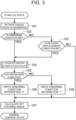
- the steering-side correction information calculation unit 53 retrieves various pieces of information from the memory 49b (step 101).
- the steering-side correction information calculation unit 53 retrieves pieces of information including the steering-side midpoint information ⁇ ns and the abnormal condition information FLG1.
- the steering-side correction information calculation unit 53 retrieves the steering-side midpoint information ⁇ ns from the storage unit 51a and retrieves the abnormal condition information FLG1 from the storage unit 51b.
- step 102 the steering-side correction information calculation unit 53 determines whether an abnormal condition is met (step 102).
- step 102 the steering-side correction information calculation unit 53 determines whether writing of the steering-side midpoint information ⁇ ns has been successfully completed based on whether the abnormal condition information FLG1 retrieved in step 101 is "0." In this embodiment, that writing of the steering-side midpoint information ⁇ ns has failed to be completed is one example of the abnormal condition.
- the process of step 102 is one example of the abnormal condition determination process.
- step 104 the steering-side correction information calculation unit 53 acquires the steering-side correction element information ⁇ cs and further writes the steering-side midpoint information ⁇ ns into the storage unit 51a through the steering-side correction information storing process.
- the steering-side correction element information ⁇ cs is one example of the correction element information.
- the steering-side midpoint information ⁇ ns is one example of the correction information.
- step 103 when the steering-side correction information calculation unit 53 retrieves the abnormal condition information FLG1 of the value "0" and determines that the abnormal condition is not met (step 102: NO), it determines whether a battery replacement condition is met (step 103).
- the steering-side correction information calculation unit 53 determines that the power source has been started for the first time since battery replacement.
- the battery replacement information FLG2 is not input, the steering-side correction information calculation unit 53 determines that the power source has been started not for the first time since battery replacement. In this embodiment, that the power source is started for the first time since battery replacement is one example of the battery replacement condition.
- the process of step 103 is one example of the battery replacement condition determination process.
- rewritable contents are cleared and initialized in association with battery replacement.
- the contents stored in the storage unit 51a and the storage unit 51b each correspond to rewritable contents and are cleared and initialized in association with battery replacement.
- the steering-side correction information calculation unit 53 determines that the contents stored in the storage unit 51a and the storage unit 51b have been cleared and initialized.
- the steering-side correction information calculation unit 53 determines that the contents stored in the storage unit 51a and the storage unit 5 1b have not been cleared and initialized.
- step 104 when the steering-side correction information calculation unit 53 determines that the battery replacement condition is met (step 103: YES), it executes the steering-side correction information storing process (step 104).
- step 104 in this case, as in the case where the determination result of step 102 is YES, the steering-side correction information calculation unit 53 acquires the steering-side correction element information ⁇ cs and further writes the steering-side midpoint information ⁇ ns into the storage unit 51a through the steering-side correction information storing process.
- the steering-side correction information calculation unit 53 determines whether writing of the steering-side midpoint information ⁇ ns into the storage unit 51a through the steering-side correction information storing process executed in step 104 has been completed (step 105).
- the steering-side correction information calculation unit 53 uses, for example, a verification function.
- the verification function is a function of retrieving the steering-side midpoint information ⁇ ns that has been written into the storage unit 51a by the process of step 104 and determining whether the retrieved steering-side midpoint information ⁇ ns matches the contents having been written by the process of step 104.
- the steering-side correction information calculation unit 53 determines that writing of the steering-side midpoint information ⁇ ns into the storage unit 51a has been completed.
- the steering-side correction information calculation unit 53 determines that writing of the steering-side midpoint information ⁇ ns into the storage unit 51a has failed to be completed.
- step 106 when the steering-side correction information calculation unit 53 determines that writing of the steering-side midpoint information ⁇ ns into the storage unit 51a has been completed (step 105: YES), it writes the abnormal condition information FLG1 of the value "0" into the storage unit 51b (step 106).
- the steering-side correction information calculation unit 53 calculates the set steering angle ⁇ s0 (step 107), and sets completion of the process to be executed in the start-up state.
- the steering-side correction information calculation unit 53 calculates the set steering angle ⁇ s0 that is obtained by correcting the rotation angle ⁇ a based on the steering-side midpoint information ⁇ ns having been written by the process of step 104.
- the set steering angle ⁇ s0 is an absolute angle relative to the steering neutral position, and is used as the steering angle ⁇ s to be used when executing the normal process.
- the steering-side control unit 50 After completion of the process to be executed in the start-up state is set, the steering-side control unit 50 makes a state transition to the normal control state where the steering-side control unit 50 executes the normal process for turning the turning wheels 5 according to the driver's steering operation.
- the rotation angle ⁇ a is one example of the state variable obtained from the steering unit 4.
- the steering angle ⁇ s i.e., the set steering angle ⁇ s0 is one example of the control variable for steering that is used when executing the normal process.
- step 105 when the steering-side correction information calculation unit 53 determines in step 105 that writing of the steering-side midpoint information ⁇ ns into the storage unit 51a has failed to be completed (step 105: NO), it writes the abnormal condition information FLG1 of the value "1" into the storage unit 51b (step 108).
- the process of step 108 is one example of the abnormality information storing process.
- the steering-side correction information calculation unit 53 calculates the set steering angle ⁇ s0 (step 107) and sets completion of the process to be executed in the start-up state.
- the steering-side correction information calculation unit 53 calculates the set steering angle ⁇ s0 that is obtained by correcting the rotation angle ⁇ a based on the steering-side midpoint information ⁇ ns having been written by the process of step 104. Even when writing fails to be completed by the process of step 104 (step 105: NO), the value of the steering-side midpoint information ⁇ ns itself has been determined to be a normal value.
- the steering-side control unit 50 makes a state transition to the normal control state where the steering-side control unit 50 executes the normal process for turning the turning wheels 5 according to the driver's steering operation.
- step 107 the steering-side correction information calculation unit 53 calculates the set steering angle ⁇ s0 that is obtained by correcting the rotation angle ⁇ a based on the steering-side midpoint information ⁇ ns having been retrieved by the process of step 101.
- step 104 the steering-side correction information calculation unit 53 does not execute the steering-side correction information storing process.
- the turning-side control unit 60 executes, through the turning-side correction information calculation unit 63, a process corresponding to the process that the steering-side correction information calculation unit 53 executes.
- the turning-side correction information calculation unit 63 retrieves various pieces of information from the memory 49b after the start signal Sig is input.
- the turning-side correction information calculation unit 63 retrieves the turning-side midpoint information ⁇ nt from the storage unit 61a and retrieves the abnormal condition information FLG1 from the storage unit 61b.
- the turning-side correction information calculation unit 63 determines whether the abnormal condition is met.
- the turning-side correction information calculation unit 63 retrieves the abnormal condition information FLG1 of the value "1" and determines that the abnormal condition is met, it executes the turning-side correction information storing process as a process corresponding to step 104.
- the turning-side correction information calculation unit 63 retrieves the abnormal condition information FLG1 of the value "0" and determines that the abnormal condition is not met, it determines whether the battery replacement condition is met as a process corresponding to step 103. When the turning-side correction information calculation unit 63 determines that the battery replacement condition is met, it executes the turning-side correction information storing process as a process corresponding to step 104.
- the turning-side correction information calculation unit 63 acquires the turning-side correction element information ⁇ ct and further writes the turning-side midpoint information ⁇ nt into the storage unit 61a through the turning-side correction information storing process.
- the turning-side correction element information ⁇ ct is one example of the correction element information.
- the turning-side midpoint information ⁇ nt is one example of the correction information.
- the turning-side correction information calculation unit 63 determines whether writing of the turning-side midpoint information ⁇ nt into the storage unit 61a has been completed through the turning-side correction information storing process. In this case, like the steering-side correction information calculation unit 53, the turning-side correction information calculation unit 63 determines, using a verification function, whether writing of the turning-side midpoint information ⁇ nt into the storage unit 61a has been completed.
- the turning-side correction information calculation unit 63 determines that writing of the turning-side midpoint information ⁇ nt into the storage unit 61a has been completed, it writes the abnormal condition information FLG1 of the value "0" into the storage unit 61b as a process corresponding to step 106.
- the turning-side correction information calculation unit 63 calculates the set pinion angle ⁇ p0 and sets completion of the process to be executed in the start-up state.
- the turning-side correction information calculation unit 63 calculates the set pinion angle ⁇ p0 that is obtained by correcting the rotation angle ⁇ b based on the turning-side midpoint information ⁇ nt having been written by the turning-side correction information storing process.
- the set pinion angle ⁇ p0 is an absolute angle relative to the rack neutral position and used as a pinion angle ⁇ p to be used when executing the normal process.
- the turning-side control unit 60 makes a state transition to the normal control state where the turning-side control unit 60 executes the normal process for turning the turning wheels 5 according to the driver's steering operation.
- the rotation angle ⁇ b is one example of the state variable that is obtained from the turning unit 6.
- the pinion angle ⁇ p i.e., the set pinion angle ⁇ p0 is one example of the control variable for turning that is used when executing the normal process.
- the turning-side correction information calculation unit 63 determines that writing of the turning-side midpoint information ⁇ nt into the storage unit 61a has failed to be completed, it writes the abnormal condition information FLG1 of the value " 1" into the storage unit 61b as a process corresponding to step 108.
- the turning-side correction information calculation unit 63 calculates the set pinion angle ⁇ p0 and sets completion of the process to be executed in the start-up state.
- the turning-side correction information calculation unit 63 calculates the set pinion angle ⁇ p0 that is obtained by correcting the rotation angle ⁇ b based on the turning-side midpoint information ⁇ nt having been written by the turning-side correction information storing process.
- the turning-side control unit 60 makes a state transition to the normal control state where the turning-side control unit 60 executes the normal process for turning the turning wheels 5 according to the driver's steering operation.
- the turning-side correction information calculation unit 63 determines that the battery replacement condition is not met, it calculates the set pinion angle ⁇ p0 and sets completion of the process to be executed in the start-up state as a process corresponding to step 107. In this case, the turning-side correction information calculation unit 63 calculates the set pinion angle ⁇ p0 that is obtained by correcting the rotation angle ⁇ b based on the turning-side midpoint information ⁇ nt having been retrieved by the process corresponding to step 101. When the turning-side correction information calculation unit 63 determines that the battery replacement condition is not met, it does not execute the turning-side correction information storing process.
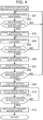
- the steering-side correction information calculation unit 53 rotates the steering wheel 3 rightward that is one of leftward and rightward directions (step 201).
- the steering-side correction information calculation unit 53 calculates the target rotation torque RT* for rotating the steering wheel 3 rightward.
- the steering-side correction information calculation unit 53 calculates the target rotation torque RT* through feedback control of a temporary steering angle ⁇ si such that the temporary steering angle ⁇ si adapts to the steering target angle ⁇ s*.
- the temporary steering angle ⁇ si is an integrated angle that is obtained using the position of the rotation angle ⁇ a at the start-up of the power source as a temporary reference value.
- the steering target angle ⁇ s* is a value that is updated so as to change gradually from the value of the temporary steering angle ⁇ si at the start of the steering-side correction information storing process to beyond the rightward rotation limit position 3a in the rotation range of the steering wheel 3.
- the steering-side correction information calculation unit 53 determines whether the steering wheel 3 has reached the rightward rotation limit position 3a (step 202).
- the steering-side correction information calculation unit 53 monitors the steering-side actual current value Ia.
- the steering-side actual current value Ia does not undergo a great change during a period until the steering wheel 3 reaches the rightward rotation limit position 3a.
- the absolute value of the steering-side actual current value Ia increases sharply when the steering wheel 3 reaches the rightward rotation limit position 3a. This is because rotation of the steering-side motor 13 is restricted as rotation of the steering shaft 11 is restricted through the stopper mechanism 11b.
- the target rotation torque RT* increases sharply and also the steering-side actual current value Ia increases sharply as the steering-side correction information calculation unit 53 tries to further rotate the steering-side motor 13 while rotation of the steering-side motor 13 is restricted.
- the steering-side correction information calculation unit 53 determines that the steering wheel 3 has reached the rightward rotation limit position 3a.
- the absolute value of the steering-side actual current value Ia is smaller than the current threshold value Iath, the steering-side correction information calculation unit 53 determines that the steering wheel 3 has not reached the rightward rotation limit position 3a.
- the current threshold value Iath is set to a value within a range that is experimentally obtained such that rotation of the steering-side motor 13 is restricted as rotation of the steering shaft 11 is restricted through the stopper mechanism 11b.
- step 202 when the steering-side correction information calculation unit 53 determines that the steering wheel 3 has not reached the rightward rotation limit position 3a (step 202: NO), it repeatedly executes the processes of step 201 and step 202.
- step 202: YES when the steering-side correction information calculation unit 53 determines that the steering wheel 3 has reached the rightward rotation limit position 3a (step 202: YES), it temporarily stores a temporary right limit position ⁇ rl (step 203).
- step 203 the steering-side correction information calculation unit 53 temporarily stores, as the temporary right limit position ⁇ rl, the temporary steering angle ⁇ si of the time when it has been determined that the rightward rotation limit position 3a has been reached.
- the temporary right limit position ⁇ rl that the steering-side correction information calculation unit 53 temporarily stores is one example of the steering-side correction element information ⁇ cs.
- the steering-side correction information calculation unit 53 rotates the steering wheel 3 leftward that is the other direction than the rightward direction (step 204).
- the steering-side correction information calculation unit 53 calculates the target rotation torque RT* for rotating the steering wheel 3 leftward.
- the steering-side correction information calculation unit 53 calculates the target rotation torque RT* through feedback control of the temporary steering angle ⁇ si such that the temporary steering angle ⁇ si adapts to the steering target angle ⁇ s*.
- the steering target angle ⁇ s* is a value that is updated so as to change gradually from the value of the temporary steering angle ⁇ si of the case where the rightward rotation limit position 3a has been reached to beyond the leftward rotation limit position 3b in the rotation range of the steering wheel 3.
- step 205 the steering-side correction information calculation unit 53 determines whether the steering wheel 3 has reached the leftward rotation limit position 3b (step 205).
- step 205 for example, the steering-side correction information calculation unit 53 monitors the steering-side actual current value Ia as in the process of step 205.
- step 205: NO when the steering-side correction information calculation unit 53 determines that the steering wheel 3 has not reached the leftward rotation limit position 3b (step 205: NO), it repeatedly executes the processes of step 204 and step 205.
- the steering-side correction information calculation unit 53 determines that the steering wheel 3 has reached the leftward rotation limit position 3b (step 205: YES)
- it temporarily stores a temporary left limit position ⁇ ll step 206.
- the steering-side correction information calculation unit 53 temporarily stores, as the temporary left limit position ⁇ ll, the temporary steering angle ⁇ si of the time when it has been determined that the leftward rotation limit position 3b has been reached.
- the temporary left limit position ⁇ ll that the steering-side correction information calculation unit 53 temporarily stores is one example of the steering-side correction element information ⁇ cs.
- the steering-side correction information calculation unit 53 calculates an actually measured steering range SR that is the steering range of the steering wheel 3 (step 207). In step 207, the steering-side correction information calculation unit 53 calculates, as the actually measured steering range SR, the absolute value of the difference between the temporary right limit position ⁇ rl temporarily stored in step 203 and the temporary left limit position ⁇ ll temporarily stored in step 206.
- the steering-side correction information calculation unit 53 determines whether the actually measured steering range SR has been normally acquired (step 208). In step 208, the steering-side correction information calculation unit 53 determines whether the absolute value of the difference between the actually measured steering range SR calculated in step 207 and a design value SR0 is smaller than a steering range threshold value SRth. For example, if the driver hinders rotation of the steering wheel 3 by touching it etc. during execution of the process of step 201 or step 204, a normal value may fail to be stored as the temporary right limit position ⁇ rl or the temporary left limit position ⁇ ll. In this case, the actually measured steering range SR may fail to be normally acquired.
- the steering-side correction information calculation unit 53 determines that the actually measured steering range SR has failed to be normally acquired.
- the steering-side correction information calculation unit 53 determines that the actually measured steering range SR has been normally acquired.
- the design value SR0 is set as a value that defines the steering range of the steering wheel 3, individually for each vehicle in which the steering device 2 is installed.
- the steering range threshold value SRth is set to a value within a range that is obtained, with a tolerance factored in, as such a range that the actually measured steering range SR can be determined not to deviate from the design value SR0 of the steering range of the steering wheel 3.
- step 208 when the steering-side correction information calculation unit 53 determines that the actually measured steering range SR has failed to be normally acquired (step 208: NO), it repeatedly executes the processes of steps 201 to 208.
- the steering-side correction information calculation unit 53 may set non-completion of the process to be executed in the start-up state. In this case, after non-completion of the process to be executed in the start-up state is set, the steering-side control unit 50 may make a state transition to a failure state, for example.
- step 209 the steering-side correction information calculation unit 53 calculates, as the actually measured neutral position, a value corresponding to a midpoint between the temporary right limit position ⁇ rl temporarily stored in step 203 and the temporary left limit position ⁇ ll temporarily stored in step 206.
- the absolute value of the difference between the actually measured neutral position and the temporary right limit position ⁇ rl and the absolute value of the difference between the actually measured neutral position and the temporary left limit position ⁇ ll are equal to each other.
- the steering-side correction information calculation unit 53 rotates the steering wheel 3 to the actually measured neutral position (step 210).
- the steering-side correction information calculation unit 53 calculates the target rotation torque RT* for rotating the steering wheel 3 to the actually measured neutral position calculated in step 209.
- the steering-side correction information calculation unit 53 calculates the target rotation torque RT* through feedback control of the temporary steering angle ⁇ si such that the temporary steering angle ⁇ si adapts to the steering target angle ⁇ s*.
- the steering target angle ⁇ s* is a value that is updated so as to change gradually to a value indicating the actually measured neutral position from the value of the temporary steering angle ⁇ si of the case where the leftward rotation limit position 3b has been reached in the rotation range of the steering wheel 3.
- the steering-side correction information calculation unit 53 determines whether the steering wheel 3 has reached the actually measured neutral position (step 211).
- the steering-side correction information calculation unit 53 monitors the temporary steering angle ⁇ si. When the temporary steering angle ⁇ si matches the actually measured neutral position, the steering-side correction information calculation unit 53 determines that the steering wheel 3 has reached the actually measured neutral position. On the other hand, when the temporary steering angle ⁇ si does not match the actually measured neutral position, the steering-side correction information calculation unit 53 determines that the steering wheel 3 has not reached the actually measured neutral position.
- step 211: NO when the steering-side correction information calculation unit 53 determines that the steering wheel 3 has not reached the actually measured neutral position (step 211: NO), it repeatedly executes the processes of step 210 and step 211.
- step 211: YES when the steering-side correction information calculation unit 53 determines that the steering wheel 3 has reached the actually measured neutral position (step 211: YES), it writes the actually measured neutral position into the storage unit 51a (step 212).
- step 212 the steering-side correction information calculation unit 53 writes the temporary steering angle ⁇ si corresponding to the actually measured neutral position calculated in step 209 as the steering-side midpoint information ⁇ ns into the storage unit 51a. Then, the steering-side correction information calculation unit 53 ends the steering-side correction information storing process and returns to the process of FIG. 3 to execute the processes of step 105 and the subsequent steps.
- FIG. 5A illustrates a case where the initial position of the steering wheel 3 at the start of execution of the steering-side correction information storing process is the steering neutral position ("0" in FIG. 5A ).
- a first value ⁇ si 1 that is the value of the temporary steering angle ⁇ si at that time is temporarily stored as the temporary right limit position ⁇ rl, i.e., the steering-side correction element information ⁇ cs.
- the steering wheel 3 starts to rotate leftward.
- the temporary steering angle ⁇ si changes gradually from "0" toward the negative value side (" ⁇ si (-)" in FIG. 5G ) following the steering target angle ⁇ s* that is updated beyond the leftward rotation limit position 3b.
- the steering wheel 3 starts rotating to the actually measured neutral position ("0" in FIG. 5E ).
- the temporary steering angle ⁇ si increases gradually from the second value ⁇ si2 toward "0" following the steering target angle ⁇ s* that is updated as the value indicating the actually measured neutral position.
- the turning-side control unit 60 does not operate the turning unit 6 in association with execution of the turning-side correction information storing process. Therefore, the turning wheels 5 are not turned during execution of the turning-side correction information storing process.
- the turning-side correction information calculation unit 63 acquires the pinion absolute rotation angle ⁇ abp (step 301) and calculates a value corresponding to the rack neutral position (step 302). In step 302, the turning-side correction information calculation unit 63 calculates the turning-side correction element information ⁇ ct that is the number of revolutions corresponding to the pinion absolute rotation angle ⁇ abp. Further, the turning-side correction information calculation unit 63 calculates a value corresponding to the rack neutral position for the pinion angle ⁇ p that is obtained by correcting the rotation angle ⁇ b based on the turning-side correction element information ⁇ ct.
- step 303 the turning-side correction information calculation unit 63 writes the value corresponding to the rack neutral position into the storage unit 61a (step 303).
- step 303 the turning-side correction information calculation unit 63 writes the value corresponding to the rack neutral position calculated in step 302 into the storage unit 61a as the turning-side midpoint information ⁇ nt.
- the turning-side correction information calculation unit 63 ends the turning-side correction information storing process and returns to the process corresponding to FIG. 3 to execute the process corresponding to step 105 and the subsequent processes.
- step 102 can be YES if, during that execution, writing of the steering-side midpoint information ⁇ ns into the storage unit 51a fails to be completed.
- the steering-side midpoint information ⁇ ns stored in the storage unit 51a cannot be used. That is, the steering angle ⁇ s deviates from the actual state of the steering unit 4.
- the steering-side control unit 50 can complete writing of the steering-side midpoint information ⁇ ns into the storage unit 51b.
- the steering-side control unit 50 can use the steering-side midpoint information ⁇ ns stored in the storage unit 51a at the next and subsequent start-up of the power source.
- the steering-side control unit 50 can create a situation where the rotation angle ⁇ a can be corrected based on the steering-side midpoint information ⁇ ns.
- the turning-side control unit 60 can complete writing of the turning-side midpoint information ⁇ nt into the storage unit 61b.
- the turning-side control unit 60 can use the turning-side midpoint information ⁇ nt stored in the storage unit 61a at the next and subsequent start-up of the power source.
- the turning-side control unit 60 can create a situation where the rotation angle ⁇ b can be corrected based on the turning-side midpoint information ⁇ nt.
- the steering-side control unit 50 is configured to store the abnormal condition information FLG1 of the value "1" into the storage unit 51b when, in the start-up state, writing of the steering-side midpoint information ⁇ ns into the storage unit 51a has failed to be completed.
- the process of determining whether the abnormal condition information FLG1 of the value "1" is stored in the storage unit 51b, i.e., whether the abnormal condition is met, is executed before the steering-side correction information storing process.
- the steering-side correction information storing process can be executed once again when the power source of the vehicle is started next time.
- the steering-side control unit 50 can correct the rotation angle ⁇ a based on the correct steering-side midpoint information ⁇ ns.
- the same also applies to the turning-side control unit 60. Specifically, even when writing of the turning-side midpoint information ⁇ nt into the storage unit 61a fails to be completed, the turning-side correction information storing process can be executed once again when the power source of the vehicle is started next time. Therefore, the turning-side control unit 60 can correct the rotation angle ⁇ b based on the correct turning-side midpoint information ⁇ nt.
- the steering-side control unit 50 is configured to determine, in the start-up state, whether the battery replacement condition is met. Further, the steering-side control unit 50 is configured to execute the steering-side correction information storing process when the battery replacement condition is met. The steering-side control unit 50 is configured to determine whether the abnormal condition is met before the process of determining whether the battery replacement condition is met. Thus, even when the battery replacement condition is not met and therefore the steering-side correction information storing process need not be executed, the steering-side correction information storing process is executed when the abnormal condition is met.
- the steering-side control unit 50 can appropriately respond to an abnormality in the storage unit 51a relating to the steering-side midpoint information ⁇ ns that has been written into the storage unit 51a through the steering-side correction information storing process.
- the reliability of the accuracy of the steering-side midpoint information ⁇ ns can be increased.
- the turning-side control unit 60 can appropriately respond to an abnormality in the storage unit 61a relating to the turning-side midpoint information ⁇ nt that has been written into the storage unit 61a through the turning-side correction information storing process.
- the reliability of the accuracy of the turning-side midpoint information ⁇ nt can be increased.
- the steering control device 1 can execute the correction information acquisition process for each unit once again.
- the steering control device 1 can correct the rotation angles ⁇ a, ⁇ b relating respectively to the steering unit 4 and the turning unit 6. Therefore, the steering angle ⁇ s and the pinion angle ⁇ p used to control the steering unit 4 and the turning unit 6, respectively, are less likely to deviate from the actual states of these units.
- the steering-side midpoint information ⁇ ns corresponding to the actual state of the steering unit 4 can be written into the storage unit 51a.
- the steering-side midpoint information ⁇ ns assumes a value reflecting the actual state of the steering unit 4. This is effective for appropriately calculating the steering angle ⁇ s that is an important parameter for controlling the steering-side motor 13.
- the turning-side control unit 60 can calculate the set pinion angle ⁇ p0 using the pinion absolute rotation angle ⁇ abp obtained from the pinion absolute angle sensor 45.
- the time taken to calculate the set pinion angle ⁇ p0 is shorter when acquiring the turning-side midpoint information ⁇ nt stored in the storage unit 61a than when acquiring the pinion absolute rotation angle ⁇ abp from the pinion absolute angle sensor 45 through a dedicated signal line. This is effective for shortening the time taken to make a state transition to the normal control state after start-up of the power source.
- the various sensors connected to the steering control device 1 include a steering absolute angle sensor 70.
- the steering absolute angle sensor 70 detects a steering absolute rotation angle ⁇ abs that is an actually measured value of the angle of a rotational axis of the steering shaft 11 within a range exceeding 360°.
- the steering absolute angle sensor 70 is provided on the steering shaft 11.
- the steering absolute angle sensor 70 is provided on the steering shaft 11, between the steering wheel 3 and the torque sensor 41.
- the steering absolute rotation angle ⁇ abs of the steering shaft 11 is used to calculate the steering angle ⁇ s.
- the steering absolute rotation angle ⁇ abs is detected, for example, as a positive value when the vehicle is steered rightward and as a negative value when the vehicle is steered leftward.
- the steering absolute angle sensor 70 is one example of the sensor that detects the actually measured value of the steering angle ⁇ s.
- the steering-side correction information calculation unit 53 retrieves various pieces of information from the memory 49b (step 401). In step 401, the steering-side correction information calculation unit 53 retrieves pieces of information including the steering-side midpoint information ⁇ ns. For example, the steering-side correction information calculation unit 53 retrieves the steering-side midpoint information ⁇ ns from the storage unit 51a.
- the steering-side correction information calculation unit 53 determines whether the battery replacement condition is met (step 402).
- the steering-side correction information calculation unit 53 determines that the battery replacement condition is met (step 402: YES)
- it executes the steering-side correction information storing process (step 403) and calculates the set steering angle ⁇ s0 (step 404).
- the steering-side correction information calculation unit 53 determines that the battery replacement condition is not met (step 402: NO)
- the steering-side correction information calculation unit 53 does not execute the steering-side correction information storing process (step 403).
- the steering-side correction information calculation unit 53 acquires the steering absolute rotation angle ⁇ abs (step 405) and determines whether an abnormal condition is met (step 406).
- the steering-side correction information calculation unit 53 determines whether the abnormal condition is met, for example, based on a result of comparing the set steering angle ⁇ s0 calculated by the process of step 404 and the steering absolute rotation angle ⁇ abs acquired by the process of step 405.
- the steering-side correction information calculation unit 53 determines whether the absolute value of the difference between the set steering angle ⁇ s0 and the steering absolute rotation angle ⁇ abs is smaller than a steering-side threshold value ⁇ ths.
- the steering-side midpoint information ⁇ ns is not a normal value, discrepancy occurs between the set steering angle ⁇ s0 and the steering absolute rotation angle ⁇ abs. In this case, the steering-side midpoint information ⁇ ns may have failed to be normally acquired.
- the steering-side correction information calculation unit 53 determines that the steering-side midpoint information ⁇ ns has failed to be normally acquired.
- the steering-side correction information calculation unit 53 determines that the steering-side midpoint information ⁇ ns has been normally acquired.
- the steering-side threshold value ⁇ ths is set to a value within a range that is obtained, with a tolerance factored in, as such a range that it can be determined that there is no discrepancy between the set steering angle ⁇ s0 and the steering absolute rotation angle ⁇ abs.
- that the steering-side midpoint information ⁇ ns has failed to be normally acquired is one example of the abnormal condition.
- the process of step 102 is one example of the abnormal condition determination process.
- step 406 determines that the abnormal condition is met (step 406: YES)
- step 406 determines that the abnormal condition is met (step 406: YES)
- step 403 executes the steering-side correction information storing process (step 403) and the subsequent processes once again.
- step 406 when the steering-side correction information calculation unit 53 determines that the abnormal condition is not met (step 406: NO), it sets completion of the process to be executed in the start-up state. After completion of the process to be executed in the start-up state is set, the steering-side control unit 50 makes a state transition to the normal control state where the steering-side control unit 50 executes the normal process for turning the turning wheels 5 according to the driver's steering operation.
- the turning-side control unit 60 executes a process in the start-up state through the turning-side correction information calculation unit 63 by a processing procedure corresponding to that of the steering-side correction information calculation unit 53. For example, as a process corresponding to step 401, the turning-side correction information calculation unit 63 retrieves various pieces of information from the memory 49b after the start signal Sig is input. In this case, the turning-side correction information calculation unit 63 retrieves the turning-side midpoint information ⁇ nt from the storage unit 61a.
- the turning-side correction information calculation unit 63 determines whether the battery replacement condition is met. When the turning-side correction information calculation unit 63 determines that the battery replacement condition is met, it executes the turning-side correction information storing process as a process corresponding to step 403 and calculates the set pinion angle ⁇ p0 as a process corresponding to step 404. On the other hand, when the turning-side correction information calculation unit 63 determines that the battery replacement condition is not met, the turning-side correction information calculation unit 63 calculates the set pinion angle ⁇ p0 as a process corresponding to step 404. When the turning-side correction information calculation unit 63 determines that the battery replacement condition is not met, it does not execute the turning-side correction information storing process.
- the turning-side correction information calculation unit 63 acquires the pinion absolute rotation angle ⁇ abp and determines whether the abnormal condition is met. In this case, the turning-side correction information calculation unit 63 determines whether the abnormal condition is met based on, for example, a result of comparing the set pinion angle ⁇ p0 calculated in the process corresponding to step 404 and the pinion absolute rotation angle ⁇ abp acquired in the process corresponding to step 405. The turning-side correction information calculation unit 63 determines whether the absolute value of the difference between the set pinion angle ⁇ p0 and the pinion absolute rotation angle ⁇ abp is smaller than a turning-side threshold value ⁇ tht.
- the turning-side midpoint information ⁇ nt is not a normal value, discrepancy occurs between the set pinion angle ⁇ p0 and the pinion absolute rotation angle ⁇ abp. In this case, the turning-side midpoint information ⁇ nt may have failed to be normally acquired.
- the absolute value of the difference between the set pinion angle ⁇ p0 and the pinion absolute rotation angle ⁇ abp is equal to or larger than the turning-side threshold value ⁇ tht, the turning-side correction information calculation unit 63 determines that the turning-side midpoint information ⁇ nt has failed to be normally acquired.
- the turning-side correction information calculation unit 63 determines that the turning-side midpoint information ⁇ nt has been normally acquired.
- the turning-side threshold value ⁇ tht is set to a value within a range that is obtained, with a tolerance factored in, as such a range that it can be determined that there is no discrepancy between the set pinion angle ⁇ p0 and the pinion absolute rotation angle ⁇ abp.
- the turning-side correction information calculation unit 63 determines that the abnormal condition is met, it returns to the process corresponding to step 403 and executes the turning-side correction information storing process and the subsequent processes once again.
- the turning-side correction information calculation unit 63 determines that the abnormal condition is not met, it sets completion of the process to be executed in the start-up state. After completion of the process to be executed in the start-up state is set, the turning-side control unit 60 makes a state transition to the normal control state where the turning-side control unit 60 executes the normal process for turning the turning wheels 5 according to the driver's steering operation.
- the second embodiment having been described above can produce workings and advantages equivalent to those of the first embodiment, as well as can produce advantages equivalent to (1-3) to (1-5) of the first embodiment.
- the second embodiment can further produce the workings and advantages described below.
- the steering device 2 includes the steering absolute angle sensor 70.
- the process of step 406 includes a process of determining whether the abnormal condition is met based on a result of comparing the set steering angle ⁇ s0 and the steering absolute rotation angle ⁇ abs.
- the process of determining whether the abnormal condition is met based on a result of comparing the set steering angle ⁇ s0 and the steering absolute rotation angle ⁇ abs is executed after the steering-side correction information storing process.
- the steering-side midpoint information ⁇ ns obtained through the steering-side correction information storing process executed during the period of the start-up state is itself not a normal value, the steering-side correction information storing process can be executed once again during the same period of the start-up state.
- the steering-side control unit 50 can correct the rotation angle ⁇ a based on the correct steering-side midpoint information ⁇ ns.
- the same also applies to the turning-side control unit 60. Specifically, even when the turning-side midpoint information ⁇ nt itself is not a normal value, the turning-side correction information storing process can be executed once again during the same period of the start-up state. Therefore, the turning-side control unit 60 can correct the rotation angle ⁇ b based on the correct turning-side midpoint information ⁇ nt.
Landscapes
- Engineering & Computer Science (AREA)
- Chemical & Material Sciences (AREA)
- Combustion & Propulsion (AREA)
- Transportation (AREA)
- Mechanical Engineering (AREA)
- Steering Control In Accordance With Driving Conditions (AREA)
- Power Steering Mechanism (AREA)
Claims (6)
- Lenksteuerungssystem, das eine Lenkvorrichtung (2) eines Fahrzeugs steuert, wobei die Lenkvorrichtung (2) eine Struktur hat, in der ein Kraftübertragungspfad zwischen einer Lenkeinheit (4), die ein Betätigungsglied hat, und einer Dreheinheit (6), die konfiguriert ist, um drehende Räder zu drehen, unterbrochen ist,
wobei das Lenksteuerungssystem aufweist:eine Speichereinheit, die Informationen speichert, die sich auf eine Steuerung der Lenkvorrichtung (2) beziehen; undeine Steuerungseinheit, die konfiguriert ist, um einen Zustandsübergang in einen normalen Steuerungszustand über einen Anlasszustand, nachdem ein Leistungsquellensystem des Fahrzeugs gestartet ist, vorzunehmen, wobei:der Anlasszustand ein Zustand ist, in dem die Steuerungseinheit einen Korrekturinformations-Speicherprozess eines Erlangens von Korrekturelementinformationen unter Verwendung einer Zustandsvariablen, die von der Lenkvorrichtung (2) erhalten wird, und ferner eines Schreibens von Korrekturinformationen, die basierend auf den erlangten Korrekturelementinformationen erhalten werden, in die Speichereinheit ausführt, undder normale Steuerungszustand ein Zustand ist, in dem die Steuerungseinheit einen normalen Prozess eines Steuerns der Lenkvorrichtung (2) unter Verwendung einer Steuerungsvariablen, die durch Korrigieren der Zustandsvariablen basierend auf den Korrekturinformationen erhalten wird, ausführt,dadurch gekennzeichnet, dassdie Steuerungseinheit konfiguriert ist, um in dem Anlasszustand einen Abnormalzustands-Bestimmungsprozess eines Bestimmens auszuführen, ob ein Abnormalzustand, der kennzeichnet, dass die Korrekturinformationen abnormal sind, die durch den Korrekturinformations-Speicherprozess in die Speichereinheit geschrieben worden sind, erfüllt ist,der Korrekturinformations-Speicherprozess ein Prozess ist, der erneut ausgeführt wird, wenn der Abnormalzustand erfüllt ist, undder Abnormalzustands-Bestimmungsprozess ein Prozess ist, der zumindest entweder vor oder nach dem Korrekturinformations-Speicherprozess ausgeführt wird. - Lenkungssteuerungssystem nach Anspruch 1, dadurch gekennzeichnet, dass:die Steuerungseinheit konfiguriert ist, um in dem Anlasszustand einen Abnormalitätsinformations-Speicherprozess eines Schreibens von Abnormalzustandsinformationen in die Speichereinheit auszuführen, wenn ein Schreiben der Korrekturinformationen in die Speichereinheit nicht abgeschlossen worden ist; undder Abnormalzustands-Bestimmungsprozess ein Prozess ist, der vor dem Korrekturinformations-Speicherprozess ausgeführt wird, und einen Prozess eines Bestimmens, dass der Abnormalzustand erfüllt ist, wenn die Abnormalzustandsinformationen in die Speichereinheit geschrieben worden sind, enthält.
- Lenkungssteuerungssystem nach Anspruch 2, dadurch gekennzeichnet, dass:die Steuerungseinheit konfiguriert ist, um in dem Anlasszustand einen Batterieaustauschzustands-Bestimmungsprozess eines Bestimmens auszuführen, ob ein Batterieaustauschzustand, der einen Zustand kennzeichnet, nachdem eine Batterie entfernt und ausgetauscht worden ist, die zu dem Leistungsquellensystem des Fahrzeugs gehört, erfüllt ist;der Korrekturinformations-Speicherprozess ein Prozess ist, der ausgeführt wird, wenn der Batterieaustauschzustand erfüllt ist, und der nicht ausgeführt wird, wenn der Batterieaustauschzustand nicht erfüllt ist; undder Abnormalzustands-Bestimmungsprozess ein Prozess ist, der vor dem Batterieaustauschzustands-Bestimmungsprozess ausgeführt wird.
- Lenkungssteuerungssystem nach Anspruch 1, dadurch gekennzeichnet, dass:die Lenkvorrichtung (2) einen Sensor enthält, der einen tatsächlich gemessenen Wert entsprechend der Steuerungsvariablen, die durch Korrektur basierend auf den Korrekturinformationen erhalten wird, erfasst; undder Abnormalzustands-Bestimmungsprozess ein Prozess ist, der nach dem Korrekturinformations-Speicherprozess ausgeführt wird, und einen Prozess eines Bestimmens, ob der Abnormalzustand erfüllt ist, basierend auf einem Ergebnis eines Vergleichens der Steuerungsvariablen, die durch Korrektur basierend auf den Korrekturinformationen erhalten wird, und dem tatsächlich gemessenen Wert, der von dem Sensor erhalten wird, enthält.
- Lenkungssteuerungssystem nach einem der Ansprüche 1 bis 4, dadurch gekennzeichnet, dass:die Korrekturinformationen lenkseitige Korrekturinformationen und drehseitige Korrekturinformationen enthalten, wobei die lenkseitigen Korrekturinformationen Informationen zum Korrigieren einer Steuerungsvariablen zum Lenken sind, die verwendet wird, wenn die Lenkeinheit (4) gesteuert wird, wobei die drehseitigen Korrekturinformationen Informationen zum Korrigieren einer Steuerungsvariablen zum Drehen sind, die verwendet wird, wenn die Dreheinheit (6) gesteuert wird;der Korrekturinformations-Speicherprozess einen lenkseitigen Korrekturinformations-Speicherprozess und einen drehseitigen Korrekturinformations-Speicherprozess enthält, wobei der lenkseitige Korrekturinformations-Speicherprozess ein Prozess eines Erlangens von lenkseitigen Korrekturelementinformationen unter Verwendung einer Zustandsvariablen, die von der Lenkeinheit (4) erhalten wird, und ferner eines Schreibens der lenkseitigen Korrekturinformationen, die basierend auf den erlangten lenkseitigen Korrekturelementinformationen erhalten werden, in die Speichereinheit ist, wobei der drehseitige Korrekturinformations-Speicherprozess ein Prozess eines Erlangens von drehseitigen Korrekturelementinformationen unter Verwendung einer Zustandsvariablen, die von der Dreheinheit (6) erhalten wird, und ferner eines Schreibens der drehseitigen Korrekturinformationen, die basierend auf den erlangten drehseitigen Korrekturelementinformationen erhalten werden, in die Speichereinheit ist; undder Abnormalzustands-Bestimmungsprozess einen Prozess eines Bestimmens, ob ein Abnormalzustand, der kennzeichnet, dass die lenkseitigen Korrekturinformationen abnormal sind, die durch den lenkseitigen Korrekturinformations-Speicherprozess in die Speichereinheit geschrieben worden sind, erfüllt ist, und einen Prozess eines Bestimmens, ob ein Abnormalzustand, der kennzeichnet, dass die drehseitigen Korrekturinformationen abnormal sind, die durch den drehseitigen Korrekturinformations-Speicherprozess in die Speichereinheit geschrieben worden sind, erfüllt ist, enthält.
- Lenksteuerungsverfahren zum Steuern einer Lenkvorrichtung (2) eines Fahrzeugs, wobei die Lenkvorrichtung (2) eine Struktur hat, in der ein Kraftübertragungspfad zwischen einer Lenkeinheit (4), die ein Betätigungsglied hat, und einer Dreheinheit (6), die konfiguriert ist, um drehende Räder (5) zu drehen, unterbrochen ist,
wobei das Lenksteuerungsverfahren aufweist:Speichern von Informationen, die sich auf eine Steuerung der Lenkvorrichtung (2) beziehen; undVornehmen eines Zustandsübergangs in einen normalen Steuerungszustand über einen Anlasszustand, nachdem ein Leistungsquellensystem des Fahrzeugs gestartet ist, wobei:der Anlasszustand ein Zustand ist, in dem ein Korrekturinformations-Speicherprozess ausgeführt wird, wobei der Korrekturinformations-Speicherprozess Korrekturelementinformationen unter Verwendung einer Zustandsvariablen, die von der Lenkvorrichtung (2) erhalten wird, erlangt und ferner Korrekturinformationen, die basierend auf den erlangten Korrekturelementinformationen erhalten werden, speichert, undder normale Steuerungszustand ein Zustand ist, in dem ein normaler Prozess ausgeführt wird, wobei der normale Prozess die Lenkvorrichtung (2) unter Verwendung einer Steuerungsvariablen, die durch Korrigieren der Zustandsvariablen basierend auf den Korrekturinformationen erhalten wird, steuert,dadurch gekennzeichnet, dassdas Verfahren ein Ausführen, in dem Anlasszustand, eines Abnormalzustands-Bestimmungsprozesses eines Bestimmens, ob ein Abnormalzustand erfüllt ist, der kennzeichnet, dass die Korrekturinformationen abnormal sind, die durch den Korrekturinformations-Speicherprozess gespeichert worden sind, enthält,der Korrekturinformations-Speicherprozess ein Prozess ist, der erneut ausgeführt wird, wenn der Abnormalzustand erfüllt ist, undder Abnormalzustands-Bestimmungsprozess ein Prozess ist, der zumindest entweder vor oder nach dem Korrekturinformations-Speicherprozess ausgeführt wird.
Applications Claiming Priority (1)
| Application Number | Priority Date | Filing Date | Title |
|---|---|---|---|
| JP2022116643A JP2024014072A (ja) | 2022-07-21 | 2022-07-21 | 操舵制御装置及び操舵制御方法 |
Publications (2)
| Publication Number | Publication Date |
|---|---|
| EP4309976A1 EP4309976A1 (de) | 2024-01-24 |
| EP4309976B1 true EP4309976B1 (de) | 2024-11-27 |
Family
ID=87419292
Family Applications (1)
| Application Number | Title | Priority Date | Filing Date |
|---|---|---|---|
| EP23186285.5A Active EP4309976B1 (de) | 2022-07-21 | 2023-07-19 | Lenksteuerungssystem und lenksteuerungsverfahren |
Country Status (4)
| Country | Link |
|---|---|
| US (1) | US12263897B2 (de) |
| EP (1) | EP4309976B1 (de) |
| JP (1) | JP2024014072A (de) |
| CN (1) | CN117429499A (de) |
Families Citing this family (4)
| Publication number | Priority date | Publication date | Assignee | Title |
|---|---|---|---|---|
| DE102020200861B4 (de) * | 2020-01-24 | 2023-10-12 | Robert Bosch Gesellschaft mit beschränkter Haftung | Verfahren zum Betrieb eines Lenksystems |
| JP2024014071A (ja) * | 2022-07-21 | 2024-02-01 | 株式会社ジェイテクト | 車両用制御装置及び車両用制御方法 |
| JP2024014072A (ja) * | 2022-07-21 | 2024-02-01 | 株式会社ジェイテクト | 操舵制御装置及び操舵制御方法 |
| JP2025182830A (ja) * | 2024-06-04 | 2025-12-16 | カヤバ株式会社 | ステアリング装置 |
Family Cites Families (29)
| Publication number | Priority date | Publication date | Assignee | Title |
|---|---|---|---|---|
| JP3853153B2 (ja) * | 2000-11-27 | 2006-12-06 | 株式会社ジェイテクト | 車両用舵角検出装置およびそれを用いたパワーステアリング装置 |
| SE524955C2 (sv) * | 2003-02-06 | 2004-10-26 | Bt Ind Ab | Anordning vid truck med elmotorservo innefattande inre positionsavkännare |
| JP4432709B2 (ja) * | 2004-10-01 | 2010-03-17 | トヨタ自動車株式会社 | 電動パワーステアリング装置 |
| EP1650105B1 (de) * | 2004-10-20 | 2007-12-12 | Jtekt Corporation | Elektrische Servolenkung |
| US7295907B2 (en) * | 2005-06-14 | 2007-11-13 | Trw Automotive U.S. Llc | Recovery of calibrated center steering position after loss of battery power |
| DE602007004029D1 (de) * | 2006-07-14 | 2010-02-11 | Nsk Ltd | Steuervorrichtung für eine Servolenkvorrichtung |
| EP2275323B1 (de) * | 2008-05-16 | 2013-04-17 | Honda Motor Co., Ltd. | Elektrische servolenkvorrichtung |
| JP4875724B2 (ja) * | 2009-05-08 | 2012-02-15 | 本田技研工業株式会社 | 車両 |
| WO2011048702A1 (ja) * | 2009-10-21 | 2011-04-28 | トヨタ自動車株式会社 | 車両の電動パワーステアリング装置 |
| JP2012131471A (ja) * | 2010-11-29 | 2012-07-12 | Honda Motor Co Ltd | 電動ステアリング装置 |
| WO2012073359A1 (ja) * | 2010-12-01 | 2012-06-07 | トヨタ自動車株式会社 | 車両の操舵制御装置 |
| JP6115757B2 (ja) * | 2012-02-17 | 2017-04-19 | 株式会社ジェイテクト | 車両用操舵装置 |
| JP6194619B2 (ja) * | 2013-04-18 | 2017-09-13 | 株式会社ジェイテクト | 電動パワーステアリング装置 |
| US9862417B2 (en) * | 2013-08-28 | 2018-01-09 | Kyocera Corporation | Turning angle correction method, turning angle correction device, image-capturing device, and turning angle correction system |
| US10494018B2 (en) * | 2016-09-16 | 2019-12-03 | Jtekt Corporation | Steering device |
| KR20180096859A (ko) * | 2017-02-20 | 2018-08-30 | 현대모비스 주식회사 | 엠디피에스의 조향각 추정 장치 및 방법 |
| JP6747367B2 (ja) * | 2017-04-18 | 2020-08-26 | 株式会社デンソー | 舵角検出装置、および、これを用いた電動パワーステアリング装置 |
| JP6760192B2 (ja) * | 2017-04-18 | 2020-09-23 | 株式会社デンソー | 舵角検出装置 |
| JP6943174B2 (ja) * | 2017-12-25 | 2021-09-29 | 株式会社ジェイテクト | 操舵制御装置 |
| JP2021075068A (ja) * | 2019-11-05 | 2021-05-20 | 株式会社ジェイテクト | 操舵システム |
| JP7332525B2 (ja) * | 2020-04-03 | 2023-08-23 | 株式会社ジェイテクト | 操舵制御装置 |
| JP7426294B2 (ja) * | 2020-06-18 | 2024-02-01 | 株式会社ジェイテクト | 操舵装置 |
| JP7502911B2 (ja) | 2020-06-18 | 2024-06-19 | 株式会社ジェイテクト | 操舵装置 |
| JP7495281B2 (ja) * | 2020-06-18 | 2024-06-04 | 株式会社ジェイテクト | 操舵装置 |
| JP7422013B2 (ja) * | 2020-06-18 | 2024-01-25 | 株式会社ジェイテクト | 操舵装置 |
| EP4522486A1 (de) * | 2022-05-13 | 2025-03-19 | Atieva, Inc. | System und verfahren zur erkennung einer fehlausgerichteten lenksäule |
| KR20230168328A (ko) * | 2022-06-07 | 2023-12-14 | 현대모비스 주식회사 | 스티어 바이 와이어 조향 시스템의 조향각 진단과 보정 장치 및 방법 |
| JP2024014072A (ja) * | 2022-07-21 | 2024-02-01 | 株式会社ジェイテクト | 操舵制御装置及び操舵制御方法 |
| JP2024014071A (ja) * | 2022-07-21 | 2024-02-01 | 株式会社ジェイテクト | 車両用制御装置及び車両用制御方法 |
-
2022
- 2022-07-21 JP JP2022116643A patent/JP2024014072A/ja active Pending
-
2023
- 2023-07-14 US US18/222,122 patent/US12263897B2/en active Active
- 2023-07-19 EP EP23186285.5A patent/EP4309976B1/de active Active
- 2023-07-19 CN CN202310890965.1A patent/CN117429499A/zh active Pending
Also Published As
| Publication number | Publication date |
|---|---|
| JP2024014072A (ja) | 2024-02-01 |
| US12263897B2 (en) | 2025-04-01 |
| US20240025473A1 (en) | 2024-01-25 |
| EP4309976A1 (de) | 2024-01-24 |
| CN117429499A (zh) | 2024-01-23 |
Similar Documents
| Publication | Publication Date | Title |
|---|---|---|
| EP4309976B1 (de) | Lenksteuerungssystem und lenksteuerungsverfahren | |
| JP7473717B2 (ja) | 操舵角を決定するための方法および制御装置 | |
| US12179853B2 (en) | Steering control device | |
| EP4219270A1 (de) | Lenksteuerungsvorrichtung und standardwerteinstellungsverfahren | |
| JP2010089690A (ja) | 電動パワーステアリング装置 | |
| EP4101733A1 (de) | Lenkungssteuerungsvorrichtung | |
| US12454306B2 (en) | Vehicle control unit and vehicle control method | |
| CN113492908B (zh) | 转向控制装置 | |
| EP4169806B1 (de) | Lenksteuervorrichtung | |
| WO2021177033A1 (ja) | 位置検出装置 | |
| JP4873159B2 (ja) | 車両の操舵装置 | |
| JP7306928B2 (ja) | 操舵制御装置 | |
| US20250010910A1 (en) | Steering control device and steering control method | |
| US20240391465A1 (en) | Turning system and control information setting method | |
| EP3792152B1 (de) | Lenkungssteuerungsvorrichtung | |
| WO2025248623A1 (ja) | 車両用操舵装置及び車両用システム | |
| JP7027985B2 (ja) | 舵角検出装置 |
Legal Events
| Date | Code | Title | Description |
|---|---|---|---|
| PUAI | Public reference made under article 153(3) epc to a published international application that has entered the european phase |
Free format text: ORIGINAL CODE: 0009012 |
|
| STAA | Information on the status of an ep patent application or granted ep patent |
Free format text: STATUS: THE APPLICATION HAS BEEN PUBLISHED |
|
| AK | Designated contracting states |
Kind code of ref document: A1 Designated state(s): AL AT BE BG CH CY CZ DE DK EE ES FI FR GB GR HR HU IE IS IT LI LT LU LV MC ME MK MT NL NO PL PT RO RS SE SI SK SM TR |
|
| STAA | Information on the status of an ep patent application or granted ep patent |
Free format text: STATUS: REQUEST FOR EXAMINATION WAS MADE |
|
| 17P | Request for examination filed |
Effective date: 20240326 |
|
| RBV | Designated contracting states (corrected) |
Designated state(s): AL AT BE BG CH CY CZ DE DK EE ES FI FR GB GR HR HU IE IS IT LI LT LU LV MC ME MK MT NL NO PL PT RO RS SE SI SK SM TR |
|
| GRAP | Despatch of communication of intention to grant a patent |
Free format text: ORIGINAL CODE: EPIDOSNIGR1 |
|
| STAA | Information on the status of an ep patent application or granted ep patent |
Free format text: STATUS: GRANT OF PATENT IS INTENDED |
|
| INTG | Intention to grant announced |
Effective date: 20240718 |
|
| GRAS | Grant fee paid |
Free format text: ORIGINAL CODE: EPIDOSNIGR3 |
|
| GRAA | (expected) grant |
Free format text: ORIGINAL CODE: 0009210 |
|
| STAA | Information on the status of an ep patent application or granted ep patent |
Free format text: STATUS: THE PATENT HAS BEEN GRANTED |
|
| RAP3 | Party data changed (applicant data changed or rights of an application transferred) |
Owner name: JTEKT CORPORATION |
|
| AK | Designated contracting states |
Kind code of ref document: B1 Designated state(s): AL AT BE BG CH CY CZ DE DK EE ES FI FR GB GR HR HU IE IS IT LI LT LU LV MC ME MK MT NL NO PL PT RO RS SE SI SK SM TR |
|
| REG | Reference to a national code |
Ref country code: GB Ref legal event code: FG4D |
|
| REG | Reference to a national code |
Ref country code: CH Ref legal event code: EP |
|
| REG | Reference to a national code |
Ref country code: IE Ref legal event code: FG4D |
|
| REG | Reference to a national code |
Ref country code: DE Ref legal event code: R096 Ref document number: 602023001170 Country of ref document: DE |
|
| REG | Reference to a national code |
Ref country code: LT Ref legal event code: MG9D |
|
| REG | Reference to a national code |
Ref country code: NL Ref legal event code: MP Effective date: 20241127 |
|
| PG25 | Lapsed in a contracting state [announced via postgrant information from national office to epo] |
Ref country code: IS Free format text: LAPSE BECAUSE OF FAILURE TO SUBMIT A TRANSLATION OF THE DESCRIPTION OR TO PAY THE FEE WITHIN THE PRESCRIBED TIME-LIMIT Effective date: 20250327 Ref country code: HR Free format text: LAPSE BECAUSE OF FAILURE TO SUBMIT A TRANSLATION OF THE DESCRIPTION OR TO PAY THE FEE WITHIN THE PRESCRIBED TIME-LIMIT Effective date: 20241127 Ref country code: PT Free format text: LAPSE BECAUSE OF FAILURE TO SUBMIT A TRANSLATION OF THE DESCRIPTION OR TO PAY THE FEE WITHIN THE PRESCRIBED TIME-LIMIT Effective date: 20250327 |
|
| PG25 | Lapsed in a contracting state [announced via postgrant information from national office to epo] |
Ref country code: FI Free format text: LAPSE BECAUSE OF FAILURE TO SUBMIT A TRANSLATION OF THE DESCRIPTION OR TO PAY THE FEE WITHIN THE PRESCRIBED TIME-LIMIT Effective date: 20241127 Ref country code: NL Free format text: LAPSE BECAUSE OF FAILURE TO SUBMIT A TRANSLATION OF THE DESCRIPTION OR TO PAY THE FEE WITHIN THE PRESCRIBED TIME-LIMIT Effective date: 20241127 |
|
| REG | Reference to a national code |
Ref country code: AT Ref legal event code: MK05 Ref document number: 1745463 Country of ref document: AT Kind code of ref document: T Effective date: 20241127 |
|
| PG25 | Lapsed in a contracting state [announced via postgrant information from national office to epo] |
Ref country code: BG Free format text: LAPSE BECAUSE OF FAILURE TO SUBMIT A TRANSLATION OF THE DESCRIPTION OR TO PAY THE FEE WITHIN THE PRESCRIBED TIME-LIMIT Effective date: 20241127 |
|
| PG25 | Lapsed in a contracting state [announced via postgrant information from national office to epo] |
Ref country code: ES Free format text: LAPSE BECAUSE OF FAILURE TO SUBMIT A TRANSLATION OF THE DESCRIPTION OR TO PAY THE FEE WITHIN THE PRESCRIBED TIME-LIMIT Effective date: 20241127 |
|
| PG25 | Lapsed in a contracting state [announced via postgrant information from national office to epo] |
Ref country code: NO Free format text: LAPSE BECAUSE OF FAILURE TO SUBMIT A TRANSLATION OF THE DESCRIPTION OR TO PAY THE FEE WITHIN THE PRESCRIBED TIME-LIMIT Effective date: 20250227 |
|
| PG25 | Lapsed in a contracting state [announced via postgrant information from national office to epo] |
Ref country code: LV Free format text: LAPSE BECAUSE OF FAILURE TO SUBMIT A TRANSLATION OF THE DESCRIPTION OR TO PAY THE FEE WITHIN THE PRESCRIBED TIME-LIMIT Effective date: 20241127 Ref country code: GR Free format text: LAPSE BECAUSE OF FAILURE TO SUBMIT A TRANSLATION OF THE DESCRIPTION OR TO PAY THE FEE WITHIN THE PRESCRIBED TIME-LIMIT Effective date: 20250228 Ref country code: AT Free format text: LAPSE BECAUSE OF FAILURE TO SUBMIT A TRANSLATION OF THE DESCRIPTION OR TO PAY THE FEE WITHIN THE PRESCRIBED TIME-LIMIT Effective date: 20241127 |
|
| PG25 | Lapsed in a contracting state [announced via postgrant information from national office to epo] |
Ref country code: PL Free format text: LAPSE BECAUSE OF FAILURE TO SUBMIT A TRANSLATION OF THE DESCRIPTION OR TO PAY THE FEE WITHIN THE PRESCRIBED TIME-LIMIT Effective date: 20241127 |
|
| PG25 | Lapsed in a contracting state [announced via postgrant information from national office to epo] |
Ref country code: RS Free format text: LAPSE BECAUSE OF FAILURE TO SUBMIT A TRANSLATION OF THE DESCRIPTION OR TO PAY THE FEE WITHIN THE PRESCRIBED TIME-LIMIT Effective date: 20250227 |
|
| PG25 | Lapsed in a contracting state [announced via postgrant information from national office to epo] |
Ref country code: SM Free format text: LAPSE BECAUSE OF FAILURE TO SUBMIT A TRANSLATION OF THE DESCRIPTION OR TO PAY THE FEE WITHIN THE PRESCRIBED TIME-LIMIT Effective date: 20241127 |
|
| PG25 | Lapsed in a contracting state [announced via postgrant information from national office to epo] |
Ref country code: DK Free format text: LAPSE BECAUSE OF FAILURE TO SUBMIT A TRANSLATION OF THE DESCRIPTION OR TO PAY THE FEE WITHIN THE PRESCRIBED TIME-LIMIT Effective date: 20241127 |
|
| PG25 | Lapsed in a contracting state [announced via postgrant information from national office to epo] |
Ref country code: EE Free format text: LAPSE BECAUSE OF FAILURE TO SUBMIT A TRANSLATION OF THE DESCRIPTION OR TO PAY THE FEE WITHIN THE PRESCRIBED TIME-LIMIT Effective date: 20241127 |
|
| PGFP | Annual fee paid to national office [announced via postgrant information from national office to epo] |
Ref country code: FR Payment date: 20250610 Year of fee payment: 3 |
|
| PG25 | Lapsed in a contracting state [announced via postgrant information from national office to epo] |
Ref country code: RO Free format text: LAPSE BECAUSE OF FAILURE TO SUBMIT A TRANSLATION OF THE DESCRIPTION OR TO PAY THE FEE WITHIN THE PRESCRIBED TIME-LIMIT Effective date: 20241127 |
|
| PG25 | Lapsed in a contracting state [announced via postgrant information from national office to epo] |
Ref country code: SK Free format text: LAPSE BECAUSE OF FAILURE TO SUBMIT A TRANSLATION OF THE DESCRIPTION OR TO PAY THE FEE WITHIN THE PRESCRIBED TIME-LIMIT Effective date: 20241127 |
|
| PG25 | Lapsed in a contracting state [announced via postgrant information from national office to epo] |
Ref country code: CZ Free format text: LAPSE BECAUSE OF FAILURE TO SUBMIT A TRANSLATION OF THE DESCRIPTION OR TO PAY THE FEE WITHIN THE PRESCRIBED TIME-LIMIT Effective date: 20241127 |
|
| PG25 | Lapsed in a contracting state [announced via postgrant information from national office to epo] |
Ref country code: IT Free format text: LAPSE BECAUSE OF FAILURE TO SUBMIT A TRANSLATION OF THE DESCRIPTION OR TO PAY THE FEE WITHIN THE PRESCRIBED TIME-LIMIT Effective date: 20241127 |
|
| REG | Reference to a national code |
Ref country code: DE Ref legal event code: R097 Ref document number: 602023001170 Country of ref document: DE |
|
| PG25 | Lapsed in a contracting state [announced via postgrant information from national office to epo] |
Ref country code: SE Free format text: LAPSE BECAUSE OF FAILURE TO SUBMIT A TRANSLATION OF THE DESCRIPTION OR TO PAY THE FEE WITHIN THE PRESCRIBED TIME-LIMIT Effective date: 20241127 |
|
| PLBE | No opposition filed within time limit |
Free format text: ORIGINAL CODE: 0009261 |
|
| STAA | Information on the status of an ep patent application or granted ep patent |
Free format text: STATUS: NO OPPOSITION FILED WITHIN TIME LIMIT |
|
| PGFP | Annual fee paid to national office [announced via postgrant information from national office to epo] |
Ref country code: DE Payment date: 20250528 Year of fee payment: 3 |
|
| 26N | No opposition filed |
Effective date: 20250828 |