EP4307408A1 - Positivelektrodenmaterial und herstellungsverfahren dafür - Google Patents
Positivelektrodenmaterial und herstellungsverfahren dafür Download PDFInfo
- Publication number
- EP4307408A1 EP4307408A1 EP22897130.5A EP22897130A EP4307408A1 EP 4307408 A1 EP4307408 A1 EP 4307408A1 EP 22897130 A EP22897130 A EP 22897130A EP 4307408 A1 EP4307408 A1 EP 4307408A1
- Authority
- EP
- European Patent Office
- Prior art keywords
- positive electrode
- core
- electrode material
- shell
- precipitation
- Prior art date
- Legal status (The legal status is an assumption and is not a legal conclusion. Google has not performed a legal analysis and makes no representation as to the accuracy of the status listed.)
- Granted
Links
Images
Classifications
-
- H—ELECTRICITY
- H01—ELECTRIC ELEMENTS
- H01M—PROCESSES OR MEANS, e.g. BATTERIES, FOR THE DIRECT CONVERSION OF CHEMICAL ENERGY INTO ELECTRICAL ENERGY
- H01M4/00—Electrodes
- H01M4/02—Electrodes composed of, or comprising, active material
- H01M4/36—Selection of substances as active materials, active masses, active liquids
- H01M4/362—Composites
- H01M4/366—Composites as layered products
-
- C—CHEMISTRY; METALLURGY
- C01—INORGANIC CHEMISTRY
- C01G—COMPOUNDS CONTAINING METALS NOT COVERED BY SUBCLASSES C01D OR C01F
- C01G53/00—Compounds of nickel
- C01G53/40—Complex oxides containing nickel and at least one other metal element
- C01G53/42—Complex oxides containing nickel and at least one other metal element containing alkali metals, e.g. LiNiO2
- C01G53/44—Complex oxides containing nickel and at least one other metal element containing alkali metals, e.g. LiNiO2 containing manganese
- C01G53/50—Complex oxides containing nickel and at least one other metal element containing alkali metals, e.g. LiNiO2 containing manganese of the type (MnO2)n-, e.g. Li(NixMn1-x)O2 or Li(MyNixMn1-x-y)O2
-
- C—CHEMISTRY; METALLURGY
- C01—INORGANIC CHEMISTRY
- C01G—COMPOUNDS CONTAINING METALS NOT COVERED BY SUBCLASSES C01D OR C01F
- C01G53/00—Compounds of nickel
- C01G53/80—Compounds containing nickel, with or without oxygen or hydrogen, and containing one or more other elements
- C01G53/82—Compounds containing nickel, with or without oxygen or hydrogen, and containing two or more other elements
-
- H—ELECTRICITY
- H01—ELECTRIC ELEMENTS
- H01M—PROCESSES OR MEANS, e.g. BATTERIES, FOR THE DIRECT CONVERSION OF CHEMICAL ENERGY INTO ELECTRICAL ENERGY
- H01M10/00—Secondary cells; Manufacture thereof
- H01M10/05—Accumulators with non-aqueous electrolyte
- H01M10/052—Li-accumulators
- H01M10/0525—Rocking-chair batteries, i.e. batteries with lithium insertion or intercalation in both electrodes; Lithium-ion batteries
-
- H—ELECTRICITY
- H01—ELECTRIC ELEMENTS
- H01M—PROCESSES OR MEANS, e.g. BATTERIES, FOR THE DIRECT CONVERSION OF CHEMICAL ENERGY INTO ELECTRICAL ENERGY
- H01M4/00—Electrodes
- H01M4/02—Electrodes composed of, or comprising, active material
- H01M4/13—Electrodes for accumulators with non-aqueous electrolyte, e.g. for lithium-accumulators; Processes of manufacture thereof
- H01M4/131—Electrodes based on mixed oxides or hydroxides, or on mixtures of oxides or hydroxides, e.g. LiCoOx
-
- H—ELECTRICITY
- H01—ELECTRIC ELEMENTS
- H01M—PROCESSES OR MEANS, e.g. BATTERIES, FOR THE DIRECT CONVERSION OF CHEMICAL ENERGY INTO ELECTRICAL ENERGY
- H01M4/00—Electrodes
- H01M4/02—Electrodes composed of, or comprising, active material
- H01M4/36—Selection of substances as active materials, active masses, active liquids
- H01M4/48—Selection of substances as active materials, active masses, active liquids of inorganic oxides or hydroxides
- H01M4/50—Selection of substances as active materials, active masses, active liquids of inorganic oxides or hydroxides of manganese
- H01M4/505—Selection of substances as active materials, active masses, active liquids of inorganic oxides or hydroxides of manganese of mixed oxides or hydroxides containing manganese for inserting or intercalating light metals, e.g. LiMn2O4 or LiMn2OxFy
-
- H—ELECTRICITY
- H01—ELECTRIC ELEMENTS
- H01M—PROCESSES OR MEANS, e.g. BATTERIES, FOR THE DIRECT CONVERSION OF CHEMICAL ENERGY INTO ELECTRICAL ENERGY
- H01M4/00—Electrodes
- H01M4/02—Electrodes composed of, or comprising, active material
- H01M4/36—Selection of substances as active materials, active masses, active liquids
- H01M4/48—Selection of substances as active materials, active masses, active liquids of inorganic oxides or hydroxides
- H01M4/52—Selection of substances as active materials, active masses, active liquids of inorganic oxides or hydroxides of nickel, cobalt or iron
- H01M4/525—Selection of substances as active materials, active masses, active liquids of inorganic oxides or hydroxides of nickel, cobalt or iron of mixed oxides or hydroxides containing iron, cobalt or nickel for inserting or intercalating light metals, e.g. LiNiO2, LiCoO2 or LiCoOxFy
-
- C—CHEMISTRY; METALLURGY
- C01—INORGANIC CHEMISTRY
- C01P—INDEXING SCHEME RELATING TO STRUCTURAL AND PHYSICAL ASPECTS OF SOLID INORGANIC COMPOUNDS
- C01P2002/00—Crystal-structural characteristics
- C01P2002/50—Solid solutions
- C01P2002/52—Solid solutions containing elements as dopants
-
- C—CHEMISTRY; METALLURGY
- C01—INORGANIC CHEMISTRY
- C01P—INDEXING SCHEME RELATING TO STRUCTURAL AND PHYSICAL ASPECTS OF SOLID INORGANIC COMPOUNDS
- C01P2004/00—Particle morphology
- C01P2004/01—Particle morphology depicted by an image
- C01P2004/03—Particle morphology depicted by an image obtained by SEM
-
- C—CHEMISTRY; METALLURGY
- C01—INORGANIC CHEMISTRY
- C01P—INDEXING SCHEME RELATING TO STRUCTURAL AND PHYSICAL ASPECTS OF SOLID INORGANIC COMPOUNDS
- C01P2004/00—Particle morphology
- C01P2004/80—Particles consisting of a mixture of two or more inorganic phases
- C01P2004/82—Particles consisting of a mixture of two or more inorganic phases two phases having the same anion, e.g. both oxidic phases
- C01P2004/84—Particles consisting of a mixture of two or more inorganic phases two phases having the same anion, e.g. both oxidic phases one phase coated with the other
-
- C—CHEMISTRY; METALLURGY
- C01—INORGANIC CHEMISTRY
- C01P—INDEXING SCHEME RELATING TO STRUCTURAL AND PHYSICAL ASPECTS OF SOLID INORGANIC COMPOUNDS
- C01P2006/00—Physical properties of inorganic compounds
- C01P2006/14—Pore volume
-
- C—CHEMISTRY; METALLURGY
- C01—INORGANIC CHEMISTRY
- C01P—INDEXING SCHEME RELATING TO STRUCTURAL AND PHYSICAL ASPECTS OF SOLID INORGANIC COMPOUNDS
- C01P2006/00—Physical properties of inorganic compounds
- C01P2006/16—Pore diameter
-
- C—CHEMISTRY; METALLURGY
- C01—INORGANIC CHEMISTRY
- C01P—INDEXING SCHEME RELATING TO STRUCTURAL AND PHYSICAL ASPECTS OF SOLID INORGANIC COMPOUNDS
- C01P2006/00—Physical properties of inorganic compounds
- C01P2006/40—Electric properties
-
- H—ELECTRICITY
- H01—ELECTRIC ELEMENTS
- H01M—PROCESSES OR MEANS, e.g. BATTERIES, FOR THE DIRECT CONVERSION OF CHEMICAL ENERGY INTO ELECTRICAL ENERGY
- H01M4/00—Electrodes
- H01M4/02—Electrodes composed of, or comprising, active material
- H01M2004/026—Electrodes composed of, or comprising, active material characterised by the polarity
- H01M2004/028—Positive electrodes
-
- Y—GENERAL TAGGING OF NEW TECHNOLOGICAL DEVELOPMENTS; GENERAL TAGGING OF CROSS-SECTIONAL TECHNOLOGIES SPANNING OVER SEVERAL SECTIONS OF THE IPC; TECHNICAL SUBJECTS COVERED BY FORMER USPC CROSS-REFERENCE ART COLLECTIONS [XRACs] AND DIGESTS
- Y02—TECHNOLOGIES OR APPLICATIONS FOR MITIGATION OR ADAPTATION AGAINST CLIMATE CHANGE
- Y02E—REDUCTION OF GREENHOUSE GAS [GHG] EMISSIONS, RELATED TO ENERGY GENERATION, TRANSMISSION OR DISTRIBUTION
- Y02E60/00—Enabling technologies; Technologies with a potential or indirect contribution to GHG emissions mitigation
- Y02E60/10—Energy storage using batteries
Definitions
- the present disclosure relates to lithium-ion batteries, in particular to a positive electrode material in a form of secondary particles having a core and a shell, and a preparation method therefor.
- Ternary materials such as LiNi x Co y Mn 1-x-y O 2 , are one of the widely used positive electrode materials. With the increasing demand for energy density of batteries, the level of nickel in the ternary materials is continuously increased.
- Positive electrode materials with high level of nickel may face problems such as fast falling of capacity and poor safety.
- the main reasons may include the follows. (1) During the delithiation in the positive electrode materials with high level of nickel, various phase transitions occur, which may lead to internal stress and strain in the particles, resulting in particle fracture, increased decay sites in the materials, structural collapse, and the like. (2) Due to the uneven distribution of lithium ions and Li/Ni disordering in the positive electrode materials, the channels for transporting lithium ions are adversely affected, so do the cycling life and safety of the materials. (3) In charging of the positive electrode materials with high level of nickel, Ni 4+ on the surface may oxidize the electrolyte and produce gases, which has a significant impact on battery safety.
- Chinese patent CN108269970B relates to a gradient doped positive electrode active material which has good interface stability, as well as a balance between high capacity and prolonged cycling performance of the material.
- Chinese patent CN1 10422889B relates to a gradient doped positive electrode active material which has advantages such as high discharge capacity, good cycling performance, and the like.
- a positive electrode material in a form of secondary particles having a core and a shell wherein the positive electrode material is configured so that the core has a porosity greater than that of the shell, and a preparation method therefor.
- Such structure at least ensures that the voids between the primary particles in the core are greater than those between the primary particles in the shell.
- the inventive structure can effectively improve the battery performances and safety of the positive electrode material, which makes it particularly suitable for lithium-ion batteries of high energy density.
- the method for preparing the positive electrode material is simple.
- a positive electrode material for lithium-ion batteries which is in a form of secondary particles having a core and a shell, wherein the core has a porosity greater than that of the shell.
- a method for preparing a positive electrode material for lithium-ion batteries wherein the positive electrode material is in a form of secondary particles having a core and a shell, and the method is characterized by comprising the steps of:
- the present invention may have the following advantageous effects.
- the present disclosure relates to a positive electrode material for lithium-ion batteries, which is in a form of secondary particles having a core and a shell, wherein the core has a porosity greater than that of the shell.
- the term "secondary particles” refers to particles formed by aggregation of a plurality of primary particles.
- the secondary particles in accordance with the present disclosure have a spherical or nearly spherical shape, such as an ellipsoid.
- the secondary particles in accordance with the present disclosure have a particle size in the order of micrometer, such as 1-100 micrometers.
- the positive electrode material containing nickel is in a form of flakes, which accumulate into the primary particles.
- the primary particles have an elongated shape with a maximum dimensional size of 300-500nm.
- the primary particles per se can be porous.
- the secondary particles composed of the primary particles can be porous.
- the porous structure includes macropores (with a diameter of 50-500nm), mesopores (20-50nm), and micropores (2-20nm).
- the porosity of the positive electrode material in accordance with the present disclosure is mainly attributable to the macropores. Those macropores are mainly voids between the primary particles.
- the porous structure of the positive electrode material in accordance with the present disclosure can be defined by "porosity".
- porosity (1- ⁇ 1/ ⁇ 2) * 100%, wherein ⁇ 1 is the compacted density, ⁇ 2 is the true density.
- the compacted density refers to the measurement value for density of the positive electrode material when it is compressed under external force to fill the voids (or macropores) between the primary particles in the positive electrode material.
- the true density refers to the measurement value for density of the positive electrode material when it is fully compressed to remove all pores.
- the compacted density and the true density can be directly measured using a compacted density meter and a true density meter, respectively.
- the positive electrode material is uniformly pressurized for 30 minutes to 20 kN.
- the core has a porosity of 50-90%, preferably 60-80%, and the shell has a porosity of 10-50%, preferably 20-40%.
- the ratio of the porosity of the core to that of the shell is greater than 1.2, preferably greater than 1.5, for example 1.5-5.0, preferably 2.0-2.5.
- the core comprises macropores with a pore size of 50-500nm, with a porosity of 60-80%, preferably 65-75% for the macropores in the core; and the shell comprises macropores with a pore size of 50-500nm, with a porosity of 20-40%, preferably 25-35% for the macropores in the shell.
- the pore volume of the positive electrode material increases as the pressure applied to the positive electrode material increases.
- the pore volume under pressure satisfies the following formula: 1 ⁇ PV 1 /PV 0 ⁇ 1.5, 1 ⁇ PV 2 /PV 0 ⁇ 4.0, 1 ⁇ PV 3 /PV 0 ⁇ 6.0 and 1 ⁇ PV 4 /PV 0 ⁇ 8; preferably 1 ⁇ PV 1 /PV 0 ⁇ 1.4, 1 ⁇ PV 2 /PV 0 ⁇ 3.5, 1 ⁇ PV 3 /PV 0 ⁇ 5.5 and 1 ⁇ PV 4 /PV 0 ⁇ 7.5.
- the composition of the positive electrode material in the present disclosure can be a doped nickel containing positive electrode material commonly used in the art.
- the average composition of the positive electrode material is: Li 0.6+ ⁇ [(Ni x1 Co y1 M 1-x1 - y1 D ⁇ 1 ) z ⁇ (Ni x2 CO y2 M 1- x2 - y2 G ⁇ 2 ) 1-z ]O 2 , 0 ⁇ 0.6, 0.6 ⁇ x1 ⁇ 1, 0.6 ⁇ x2 ⁇ 1, 0 ⁇ y1 ⁇ 0.4, 0 ⁇ y2 ⁇ 0.4, 0 ⁇ z ⁇ 1, 0 ⁇ 0.1, 0 ⁇ 2 ⁇ 0.1, where M is one or two of Mn and Al, D is one or more of Mo, Ti, Y, W, Ta, Nb, Cr, Sm, Sb, V, La, Ca, Hf and Zr, and G is one or more of Mo, Ta, Zn, Ti, Y, Zr, W, Nb, Cr
- D and G are in a concentration gradient in the core and shell of the positive electrode material, respectively.
- the concentration of D gradually decreases radially from the center of the core to the surface of the core
- the concentration of G gradually increases radially from the surface of the core to the surface of the shell.
- nickel, cobalt and M i.e. manganese and/or aluminum
- the concentration of manganese gradually increases radially from the center of the core to the surface of the core
- the concentration of nickel gradually decreases radially from the surface of the core to the surface of the shell.
- a method for preparing a positive electrode material for lithium-ion batteries wherein the positive electrode material is in a form of secondary particles having a core and a shell, and the method is characterized by comprising the steps of:
- the step (1) comprises: operating the first co-precipitation at a pH of 9-12.5, preferably 10-12; and the step (2) comprises: operating the second co-precipitation at a pH of 10-13, preferably 11-13.
- the pH used for the first co-precipitation is 0.5-2, preferably 0.5-1 lower than that used for the second co-precipitation.
- the step (1) comprises: operating the first co-precipitation at a temperature of 45-65°C, preferably 50-60°C; and the step (2) comprises: operating the second co-precipitation at a temperature of 50-70°C, preferably 55-65°C.
- the step (1) comprises: operating the first co-precipitation in the presence of a complexing agent; and the step (2) comprises: operating the second co-precipitation in the presence of a complexing agent.
- the complexing agent used for the first co-precipitation is in a concentration of 5-12mol/L, preferably 7-10mol/L; and the complexing agent used for the second co-precipitation is in a concentration of 0.1-5mol/L, preferably 0.5-4.5mol/L.
- the complexing agent used for the first co-precipitation is in a concentration higher than that used for the second co-precipitation, for example, 3.0-9.0mol/L higher than that.
- the complexing agent used for the first co-precipitation is the same or different from that used for the second co-precipitation.
- the complexing agent is one or more selected from the group consisting of ammonia, ammonium sulfate, ammonium chloride and ammonium nitrate.
- the soluble salt of nickel is one or more selected from the group consisting of nickel sulfate, nickel chloride, nickel nitrate and nickel acetate.
- the soluble salt of cobalt is one or more selected from the group consisting of cobalt sulfate, cobalt chloride, cobalt nitrate and cobalt acetate.
- M manganese
- the soluble salt of manganese is one or more selected from the group consisting of manganese sulfate, manganese chloride, manganese nitrate and manganese acetate.
- M aluminum
- the soluble salt of the aluminum is one or more selected from the group consisting of sodium metaaluminate and alumina sol.
- the dispersion of D may be a sol containing elemental D or a solution containing soluble salts of D, such as a solution of one or more selected from the group consisting of sulfate, chloride and nitrate of D.
- the dispersion of G may be a sol containing elemental G or a solution containing soluble salts of G, such as a solution of one or more selected from the group consisting of sulfate, chloride and nitrate of G.
- the concentration or flow rate of the dispersion of D is controlled in step (1), so as to make the concentration of D gradually decrease radially from the center of the core to the surface of the core.
- the concentration or flow rate of the dispersion of G is controlled in step (2), so as to make the concentration of G gradually increase radially from the surface of the core to the surface of the shell.
- the dispersion of D is added at a gradually decreasing concentration in step (1), and the dispersion of G is added at a gradually increasing concentration in step (2).
- the dispersion of D is added at a gradually decreasing flow rate in step (1), and the dispersion of G is added at a gradually increasing flow rate in step (2).
- precipitants are one or more selected from the group consisting of sodium hydroxide, potassium hydroxide and lithium hydroxide.
- the antioxidants are one or more selected from the group consisting of ascorbic acid, sodium bisulfite and tea polyphenols.
- the processing aids are one or more selected from the group consisting of polyvinyl pyrrolidone, polyvinyl alcohol and sodium dodecyl sulfate. The added amounts of precipitants, antioxidants and processing aids are well-known to those skilled persons in the art.
- the first and second co-precipitations may be operated under a protective atmosphere.
- the protective atmosphere is one or more selected from the group consisting of nitrogen and inert gases.
- the inert gases may be for example argon.
- the step (3) of converting the secondary particles obtained in step (2) into the positive electrode material may comprise: calcining the secondary particles obtained in step (2) with a lithium source material at 300-1000°C, preferably 500-900°C for 1-36 hours, preferably 6-24 hours.
- the lithium source material is one or more of Li 2 O, LiOH, LiOH ⁇ H 2 O, LiNO 3 and Li 2 CO 3 , preferably LiOH or LiOH ⁇ H 2 O.
- the calcining is operated under an atmosphere containing oxygen, such as in the presence of air or oxygen.
- the positive electrode material in accordance with the present disclosure may be used in secondary batteries, such as lithium-ion batteries.
- Lithium-ion batteries may comprise a negative electrode, a positive electrode, a separator and an electrolyte.
- the positive electrode includes a positive electrode material layer on the positive current collector, wherein the positive electrode material layer comprises the positive electrode material in accordance with the present disclosure.
- the positive electrode material layer may further comprise an binder and a conductive agent.
- the binder may be resin materials selected from polyvinylidene fluoride (PVDF), polytetrafluoroethylene (PTFE), polyacrylonitrile (PAN), styrene butadiene rubber (SBR), carboxymethyl cellulose (CMC) and the like.
- the conductive agent may include carbon based materials or conductive polymers.
- the carbon based materials may comprise, for example, graphite, acetylene black, carbon fibers, nanotubes, graphene and carbon black.
- the conductive polymers may include polyaniline, polythiophene, polyacetylene, polypyrrole and the like.
- the current collector may include at least one of stainless steel, aluminum, nickel, iron, titanium, copper, tin or any other conductive materials known to those skilled in the art. In some variants, the current collector may be precoated, such as carbon coated aluminum foil.
- composition of the negative electrode in the present disclosure may be a negative electrode commonly used in the art, such as a lithium metal sheet.
- the separator may be a separator commonly used in the art.
- the separator may be a porous membrane made of polyolefins such as polytetrafluoroethylene, polypropylene or polyethylene.
- the electrolyte may be various conventional electrolytes, such as non-aqueous electrolyte.
- the non-aqueous electrolyte is a solution formed by an electrolyte lithium salt in a non-aqueous solvent. Any traditional non-aqueous electrolyte known to those skilled persons in the art may be used.
- the electrolyte may be at least one selected from the group consisting of lithium hexafluorophosphate (LiPF 6 ), lithium perchlorate (LiClO 4 ), lithium tetrafluoroborate (LiBF 4 ), lithium hexafluoroarsenate (LiAsF 6 ) and lithium hexafluorosilicate (LiSiF 6 ).
- the non-aqueous solvent may be selected from the group consisting of linear esters, cyclic esters and mixtures thereof.
- the linear esters may be at least one selected from the group consisting of dimethyl carbonate (DMC), diethyl carbonate (DEC), methyl ethyl carbonate (EMC), methyl propyl carbonate (MPC) and dipropyl carbonate (DPC).
- the cyclic esters may be at least one selected from the group consisting of ethylene carbonate (EC), propylene carbonate (PC) and vinylene carbonate (VC).
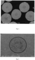
- the morphology of the sample was characterized by using a scanning electron microscope. Specifically, the Smartlab tester from Hitachi High Tech Group was used for the testing with magnification of 3000 and 10000 times respectively.
- the compacted density of the sample was characterized by using a compacted density meter. Specifically, the MCP-PD51 tester from Mitsubishi Chemical, Japan was used, where the sample was uniformly pressurized for 30 minutes to 20 kN and the test results were obtained from the testing software.
- the true density of the sample was characterized by using a true density meter. Specifically, the AccuPyc13400 tester from Micromeritics, US was used, wherein the test results were obtained from the testing software.
- the adsorption curve of the sample was obtained by using the Tri-star 3020 specific surface analyzer from Micromeritics, US.
- the sample was pretreated at conditions of a heating temperature of 300°C and a degassing time of 120 minutes.
- the pore size of the sample was calculated according to the BJH method and the pore volume of the sample was calculated according to the BET method.
- 3g of the sample was applied a pressure of 0 tons, 1.5 tons, 2.5 tons, 3.5 tons and 4.5 tons respectively to obtain the compressed samples.
- the above testing for pore size and pore volume was repeated with each of the compressed samples to obtain data of the pore volumes for pores with a pore size of 90 ⁇ 10 nm, namely PV 0 , PV 1 , PV 2 , PV 3 and PV 4 .
- the ratios of PV 1 , PV 2 , PV 3 and PV 4 to PV 0 were respectively calculated to characterize the change in pore volume under pressure for the pores with a pore size of 90 ⁇ 10 nm.
- the positive electrode active material sample 9.2 g of the positive electrode active material sample, 0.4 g of acetylene black and 0.4 g of polyvinylidene fluoride (PVDF) were mixed to form a positive electrode slurry.
- the positive electrode slurry was coated on an aluminum foil, dried, pressed under a pressure of 100 Mpa into a shape with a diameter of 12 mm and a thickness of 120 ⁇ m, and then dried in a vacuum drying oven at 120°C for 12 hours to obtain the positive electrode plate.
- PVDF polyvinylidene fluoride
- a Li metal sheet with a diameter of 17 mm and a thickness of 1 mm was used as the negative electrode.
- a porous film of polyethylene with a thickness of 25 ⁇ m was used as the separator.
- a solution of 1.0 mol/L LiPF 6 was used as the electrolyte, wherein a mixture of ethylene carbonate (EC) and diethyl carbonate (DEC) in equivalent amounts was used as the solvent.
- a 2025 coin cell was assembled by using the positive electrode plate, the separator, the negative electrode plate and the electrolyte.
- the prepared coin cell sample was set for 24 hours.
- the sample was charged at a current density of 20 mA/g to the cutoff voltage of 4.3 V, and charged at a constant voltage of 4.3 V for 30 minutes. Then it was discharged at a current density of 20 mA/g to the cutoff voltage of 3.0 V.
- the discharge time was recorded.
- the initial specific discharge capacity of the cell sample the current density * the discharge time.
- the cell sample was charged and discharged twice at a current density of 20 mA/g and a cutoff voltage of 3.0-4.3 V to complete the activation of the same.
- the activated cell sample was subjected to a specified number of charge and discharge cycles, such as 80 cycles, at a current density of 1C, a voltage range of 3.0-4.3 V and a temperature of 45°C.
- the specific discharge capacity at each cycle was obtained from the current density and the discharge time of each cycle.
- Nickel sulfate, cobalt sulfate and manganese sulfate were mixed in a molar ratio of 0.88:0.05:0.07 to form a 1.5 mol/L aqueous solution of transition metal salts.
- Nano ZrO 2 was mixed with water to form a 0.5 mol/L solution of Zr dopant.
- the aqueous solution of transition metal salts, the solution of Zr dopant, 6.0 mol/L NaOH and 3.0 mol/L NH 3 ⁇ H 2 O were slowly added to a reactor under stirring.
- Co-precipitation was operated at a pH of 12.0 and a temperature of 55°C under a N 2 atmosphere. After 70 hours of the reaction, secondary particles with a total particle size of 14.2 ⁇ m were obtained.
- the secondary particles were mixed with lithium hydroxide and calcined under an oxygen atmosphere at 735°C for 15 hours to obtain a comparative positive electrode material CC-1, which had the composition of Li 1.04 Ni 0.88 Co 0.05 Mn 0.06 Zr 0.01 O 2 .
- the performances of the comparative positive electrode material CC-1 were tested as described above. The test results showed that the comparative positive electrode material CC-1 was not in a core-shell structure, and the comparative positive electrode material CC-1 had a porosity of 65%.
- Nickel sulfate, cobalt sulfate and manganese sulfate were mixed in a molar ratio of 0.88:0.05:0.07 to form a 1.5 mol/L aqueous solution of transition metal salts.
- Nano ZrO 2 was mixed with water to form a 0.5 mol/L solution of Zr dopant.
- the aqueous solution of transition metal salts, the solution of Zr dopant, 6.0 mol/L NaOH and 3.0 mol/L NH 3 ⁇ H 2 O were slowly added to a reactor under stirring.
- the first co-precipitation was operated at a pH of 12.5 and a temperature of 60°C under a N 2 atmosphere.
- the second co-precipitation was operated at a pH of 11.0, with 8.0 mol/L NH 3 ⁇ H 2 O, at a temperature of 55°C and under a N 2 atmosphere. After 30 hours of the second co-precipitation, secondary particles with a total particle size of 14.1 ⁇ m were obtained.
- the secondary particles were mixed with lithium hydroxide and calcined under an oxygen atmosphere at 735°C for 15 hours to obtain a comparative positive electrode material CC-2, which had the composition of Li 1.04 Ni 0.88 Co 0.05 Mn 0.06 Zr 0.01 O 2 .
- the performances of the comparative positive electrode material CC-2 were tested as described above.
- the test results showed that the comparative positive electrode material CC-2 was in a core-shell structure, wherein the core had a radius of 1.5 ⁇ m, as shown in the scanning electron microscope testing results.
- the results of the testing for pore size, porosity and pore volume showed that the shell had a porosity of 71%, and the core had a porosity of 30%.
- Nickel sulfate, cobalt sulfate and manganese sulfate were mixed in a molar ratio of 0.97:0.02:0.01 to form a 1.5 mol/L aqueous solution (1) of transition metal salts.
- Nickel sulfate, cobalt sulfate and manganese sulfate were mixed in a molar ratio of 0.94:0.02:0.04 to form a 1.5 mol/L aqueous solution (2) of transition metal salts.
- Nano Nb 2 O 5 was mixed with water to form a 0.5 mol/L solution (3) of Nb dopant and a 0.01 mol/L solution (4) of Nb dopant, respectively.
- the aqueous solution (2) of transition metal salts was added into the aqueous solution (1) of transition metal salts at a flow rate of 0.2 L/h to form a mixed aqueous solution of transition metal salts, and the solution (4) of Nb dopant was added into the solution (3) of Nb dopant at a flow rate of 0.1 L/h to form a mixed solution of Nb dopant.
- the mixed aqueous solution of transition metal salts, the mixed solution of Nb dopant, 6.0 mol/L NaOH and 3.0 mol/L NH 3 ⁇ H 2 O were slowly added to a reactor under stirring.
- the first co-precipitation was operated at a pH of 12.0 and a temperature of 55°C under a N 2 atmosphere.
- the first co-precipitation was operated for 40 hours.
- Nickel sulfate, cobalt sulfate and manganese sulfate were mixed in a molar ratio of 0.86:0.05:0.09 to form a 1.5 mol/L aqueous solution (5) of transition metal salts.
- Nano ZrO 2 was mixed with water to form a 0.01 mol/L solution (6) of Zr dopant and a 1.0 mol/L solution (7) of Zr dopant respectively.
- the solution (7) of Zr dopant was added into the solution (6) of Zr dopant at a flow rate of 0.1 L/h to form a mixed solution of Zr dopant.
- the aqueous solution (5) of transition metal salts, the mixed solution of Zr dopant, 6.0 mol/L NaOH and 3.0 mol/L NH 3 ⁇ H 2 O were slowly added to the reactor wherein the first co-precipitation was just finished.
- the second co-precipitation was operated at a pH of 12 and a temperature of 55°C under a N 2 atmosphere. After 30 hours of the second co-precipitation, the adding of the aqueous solution (5) of transition metal salts was stopped. After further 0.5 hours of reaction, secondary particles with a total particle size of 14.0 ⁇ m were obtained.
- the secondary particles were mixed with lithium hydroxide and calcined under an oxygen atmosphere at 735°C for 15 hours to obtain a comparative positive electrode material CC-3, which had the composition of Li [(Ni 0.95 Co 0.02 Mn 0.02 Nb 0.01 ) 0.014 ⁇ (Ni 0.875 Co 0.05 Mn 0.07 Zr 0.005 ) 0.986 ]O 2 .
- the Nb content decreased radially from the center of the core to the surface of the core, from a molar content of 0.02 mol% to 0; while the Mn content increased radially from the center of the core to the surface of the core, from a molar content of 0.01 mol% to 0.03 mol%; and the total amount of Nb and Mn remained at 0.03mol%.
- the Zr content increased radially from the surface of the core to the surface of the shell, from a molar content of 0 to 0.01 mol%; while the Ni content decreased radially from the surface of the core to the surface of the shell, from a molar content of 0.91 mol% to 0.85 mol%.
- the Mn content increased radially from the surface of the core to the surface of the shell, from a molar content of 0.04 mol% to 0.08 mol%.
- the performances of the comparative positive electrode material CC-3 were tested as described above.
- the test results showed that the comparative positive electrode material CC-3 was in a core-shell structure, wherein the core had a radius of 1.7 ⁇ m, as shown in the scanning electron microscope testing results.
- the results of the testing for pore size, porosity and pore volume showed that the shell had a porosity of 33% and the core had a porosity of 33%.
- the coin cell prepared by using the comparative positive electrode material CC-3 of Comparative Example 3 had a capacity retention of 91.5% after 80 cycles.
- Comparative Example 3 was repeated except that the first co-precipitation was operated at a pH of 12.5, with 3.0 mol/L NH 3 ⁇ H 2 O, at a temperature of 60°C and under a N 2 atmosphere; and the second co-precipitation was operated at a pH of 11.5, with 8.0 mol/L NH 3 ⁇ H 2 O, at a temperature of 55°C and under a N 2 atmosphere. Obtained was the comparative positive electrode material CC-4, which had the same chemical composition as the comparative positive electrode material CC-3.
- the performances of the comparative positive electrode material CC-4 were tested as described above.
- the test results showed that the comparative positive electrode material CC-4 was in a core-shell structure, wherein the core had a radius of 3.4 ⁇ m, as shown in the scanning electron microscope testing results.
- the results of the testing for pore size, porosity and pore volume showed that the shell had a porosity of 73%, and the core had a porosity of 32%.
- the coin cell prepared by using the comparative positive electrode material CC-4 of Comparative Example 4 had a capacity retention of 89.2% after 80 cycles.
- Nickel sulfate, cobalt sulfate and manganese sulfate were mixed in a molar ratio of 0.97:0.02:0.01 to form a 1.5 mol/L aqueous solution (1) of transition metal salts.
- Nickel sulfate, cobalt sulfate and manganese sulfate were mixed in a molar ratio of 0.94:0.02:0.04 to form a 1.5 mol/L aqueous solution (2) of transition metal salts.
- Nano Nb 2 O 5 was mixed with water to form a 0.5 mol/L solution (3) of Nb dopant and a 0.1 mol/L solution (4) of Nb dopant, respectively.
- the aqueous solution (2) of transition metal salts was added into the aqueous solution (1) of transition metal salts at a flow rate of 0.2 L/h to form a mixed aqueous solution of transition metal salts, and the solution (4) of Nb dopant was added into the solution (3) of Nb dopant at a flow rate of 0.1 L/h to form a mixed solution of Nb dopant.
- the mixed aqueous solution of transition metal salts, the mixed solution of Nb dopant, 6.0 mol/L NaOH and 8.0 mol/L NH 3 ⁇ H 2 O were slowly added to a reactor under stirring.
- the first co-precipitation was operated at a pH of 11.0 and a temperature of 53°C under a N 2 atmosphere.
- the first co-precipitation was operated for 60 hours.
- Nickel sulfate, cobalt sulfate and manganese sulfate were mixed in a molar ratio of 0.86:0.05:0.09 to form a 1.5 mol/L aqueous solution (5) of transition metal salts.
- Nano ZrO 2 was mixed with water to form a 0.01 mol/L solution (6) of Zr dopant and a 1.0 mol/L solution (7) of Zr dopant respectively.
- the solution (7) of Zr dopant was added into the solution (6) of Zr dopant at a flow rate of 0.1 L/h to form a mixed solution of Zr dopant.
- the aqueous solution (5) of transition metal salts, the mixed solution of Zr dopant, 6.0 mol/L NaOH and 3.0 mol/L NH 3 ⁇ H 2 O were slowly added to the reactor wherein the first co-precipitation was just finished.
- the second co-precipitation was operated at a pH of 11.5 and a temperature of 58°C under a N 2 atmosphere. After 40 hours of the second co-precipitation, the adding of the aqueous solution (5) of transition metal salts was stopped. After further 0.5 hours of reaction, secondary particles with a total particle size of 14.0 ⁇ m were obtained.
- the secondary particles were mixed with lithium hydroxide and calcined under an oxygen atmosphere at 735°C for 15 hours to obtain a positive electrode material C-1, which had the composition of Li [(Ni 0.95 Co 0.02 Mn 0.02 Nb 0.01 ) 0.014 ⁇ (Ni 0.875 Co 0.05 Mn 0.07 Zr 0.005 ) 0.986 ]O 2 .
- the Nb content decreased radially from the center of the core to the surface of the core, from a molar content of 0.02 mol% to 0; while the Mn content increased radially from the center of the core to the surface of the core, from a molar content of 0.01 mol% to 0.03 mol%; and the total amount of Nb and Mn remained at 0.03mol%.
- the Zr content increased radially from the surface of the core to the surface of the shell, from a molar content of 0 to 0.01 mol%; while the Ni content decreased radially from the surface of the core to the surface of the shell, from a molar content of 0.91 mol% to 0.85 mol%. Additionally, the Mn content increased radially from the surface of the core to the surface of the shell, from a molar content of 0.04 mol% to 0.08 mol%.
- the positive electrode material C-1 was spherical particles in a core-shell structure, wherein the core had a radius of 1.7 ⁇ m, and the shell had an outer radius of 5.3 ⁇ m. The core and the shell had different voids.
- the results of the testing for pore size, porosity and pore volume showed that the core had a porosity of 70%, and the shell had a porosity of 32%.
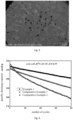
- the cycling performance of the coin cell prepared by using the positive electrode material C-1 of Example 1 was shown in Fig. 4 .
- the positive electrode material C-1 of Example 1 achieved higher capacity retention after the same number of cycles.
- the coin cell prepared by using the positive electrode material C-1 of Example 1 had a capacity retention of 93.9% after 80 cycles.
- Nickel sulfate, cobalt sulfate and manganese sulfate were mixed in a molar ratio of 0.89:0.055:0.055 to form a 1.5 mol/L aqueous solution (1) of transition metal salts.
- Nano ZrO 2 was mixed with water to form a 0.5 mol/L solution (2) of Zr dopant.
- Nano Nb 2 O 5 was mixed with water to form a 0.5 mol/L solution (3) of Nb dopant.
- the aqueous solution (1) of transition metal salts, the solution (2) of Zr dopant, the solution (3) of Nb dopant, 6.0 mol/L NaOH and 8.0 mol/L NH 3 ⁇ H 2 O were slowly added to a reactor under stirring.
- the first co-precipitation was operated at a pH of 11.5 and a temperature of 54°C under a N 2 atmosphere.
- the second co-precipitation was operated at a pH of 12.5, with 2.5 mol/L NH 3 ⁇ H 2 O, at a temperature of 58°C under a N 2 atmosphere.
- secondary particles with a total particle size of 14.1 ⁇ m were obtained.
- the secondary particles were mixed with lithium hydroxide and calcined under an oxygen atmosphere at 735°C for 15 hours to obtain a positive electrode material C-2, which had the composition of Li 1.05 [(Ni 0.95 Co 0.05 Mn 0.015 Nb 0.015 ) 0.10 ⁇ (Ni 0.905 Co 0.05 Mn 0.035 Zr 0.01 ) 0.901 O 2 .
- the positive electrode material C-2 was in a core-shell structure, wherein the core had a radius of 1.5 ⁇ m, and the shell had an outer radius of 5.6 ⁇ m.
- the core and the shell had different voids.
- the core had a porosity of 65%, and the shell had a porosity of 30%.
- the coin cell prepared by using the positive electrode material C-2 of Example 2 had a capacity retention of 93.1% after 80 cycles.
- Nickel sulfate, cobalt sulfate and manganese sulfate were mixed in a molar ratio of 0.97:0.02:0.01 to form a 1.5 mol/L aqueous solution (1) of transition metal salts.
- Nickel sulfate, cobalt sulfate and manganese sulfate were mixed in a molar ratio of 0.94:0.02:0.04 to form a 1.5 mol/L aqueous solution (2) of transition metal salts.
- Nano Nb 2 O 5 was mixed with water to form a 2 mol/L solution (3) of Nb dopant and a 0.05 mol/L solution (4) of Nb dopant, respectively.
- the aqueous solution (2) of transition metal salts was added into the aqueous solution (1) of transition metal salts at a flow rate of 0.2 L/h to form a mixed aqueous solution of transition metal salts, and the solution (4) of Nb dopant was added into the solution (3) of Nb dopant at a flow rate of 0.1 L/h to form a mixed solution of Nb dopant.
- the mixed aqueous solution of transition metal salts, the mixed solution of Nb dopant, 6.0 mol/L NaOH and 9.0 mol/L NH 3 ⁇ H 2 O were slowly added to a reactor under stirring.
- the first co-precipitation was operated at a pH of 10.0 and a temperature of 53°C under a N 2 atmosphere.
- the first co-precipitation was operated for 58 hours.
- Nickel sulfate, cobalt sulfate and manganese sulfate were mixed in a molar ratio of 0.89:0.055:0.055 to form a 1.5 mol/L aqueous solution (5) of transition metal salts.
- Nano ZrO 2 was mixed with water to form a 0.01 mol/L solution (6) of Zr dopant and a 2.0 mol/L solution (7) of Zr dopant respectively.
- the solution (7) of Zr dopant was added into the solution (6) of Zr dopant at a flow rate of 0.1 L/h to form a mixed solution of Zr dopant.
- the aqueous solution (5) of transition metal salts, the mixed solution of Zr dopant, 6.0 mol/L NaOH and 2.0 mol/L NH 3 ⁇ H 2 O were slowly added to the reactor wherein the first co-precipitation was just finished.
- the second co-precipitation was operated at a pH of 11.5 and a temperature of 56°C under a N 2 atmosphere. After 44 hours of the second co-precipitation, the adding of the aqueous solution (5) of transition metal salts was stopped. After further 0.5 hours of reaction, secondary particles with a total particle size of 14.9 ⁇ m were obtained.
- the secondary particles were mixed with lithium hydroxide and calcined under an oxygen atmosphere at 740°C for 15 hours to obtain a positive electrode material C-3, which had the composition of Li 1.05 [(Ni 0.95 Co 0.02 Mn 0.015 Nb 0.015 ) 0.10 ⁇ (Ni 0.905 Co 0.05 Mn 0.035 Zr 0.01 ) 0.90 ]O 2 .
- the Nb content decreased radially from the center of the core to the surface of the core, from a molar content of 0.02 mol% to 0.01 mol%; while the Mn content increased radially from the center of the core to the surface of the core, from a molar content of 0.01 mol% to 0.02 mol%; and the total amount of Nb and Mn remained at 0.015mol%.
- the Zr content increased radially from the surface of the core to the surface of the shell, from a molar content of 0 to 0.02 mol%; while the Ni content decreased radially from the surface of the core to the surface of the shell, from a molar content of 0.93 mol% to 0.88 mol%.
- the Mn content increased radially from the surface of the core to the surface of the shell, from a molar content of 0.02 mol% to 0.05 mol%.
- the positive electrode material C-3 was in a core-shell structure, wherein the core had a radius of 3.5 ⁇ m, and the shell had an outer radius of 4.0 ⁇ m.
- the core and the shell had different voids.
- the core had a porosity of 72%, and the shell had a porosity of 32%.
- the coin cell prepared by using the positive electrode material C-3 of Example 3 had a capacity retention of 93.1% after 80 cycles.
- Nickel sulfate, cobalt sulfate and manganese sulfate were mixed in a molar ratio of 0.87:0.02:0.11 to form a 1.5 mol/L aqueous solution (1) of transition metal salts.
- Nickel sulfate, cobalt sulfate and manganese sulfate were mixed in a molar ratio of 0.84:0.02:0.14 to form a 1.5 mol/L aqueous solution (2) of transition metal salts.
- Nano Nb 2 O 5 was mixed with water to form a 2.0 mol/L solution (3) of Nb dopant and a 0.05 mol/L solution (4) of Nb dopant, respectively.
- the aqueous solution (2) of transition metal salts was added into the aqueous solution (1) of transition metal salts at a flow rate of 0.2 L/h to form a mixed aqueous solution of transition metal salts, and the solution (4) of Nb dopant was added into the solution (3) of Nb dopant at a flow rate of 0.1 L/h to form a mixed solution of Nb dopant.
- the mixed aqueous solution of transition metal salts, the mixed solution of Nb dopant, 6.0 mol/L NaOH and 10.0 mol/L NH 3 ⁇ H 2 O were slowly added to a reactor under stirring.
- the first co-precipitation was operated at a pH of 10.8 and a temperature of 52°C under a N 2 atmosphere.
- the first co-precipitation was operated for 60 hours.
- Nickel sulfate, cobalt sulfate and manganese sulfate were mixed in a molar ratio of 0.60:0.05:0.35 to form a 1.5 mol/L aqueous solution (5) of transition metal salts.
- Nano ZrO 2 was mixed with water to form a 0.01 mol/L solution (6) of Zr dopant and a 2.0 mol/L solution (7) of Zr dopant respectively.
- the solution (7) of Zr dopant was added into the solution (6) of Zr dopant at a flow rate of 0.1 L/h to form a mixed solution of Zr dopant.
- the aqueous solution (5) of transition metal salts, the mixed solution of Zr dopant, 6.0 mol/L NaOH and 4.0 mol/L NH 3 ⁇ H 2 O were slowly added to the reactor wherein the first co-precipitation was just finished.
- the second co-precipitation was operated at a pH of 11.5 and a temperature of 58°C under a N 2 atmosphere. After 60 hours of the second co-precipitation, the adding of the aqueous solution (5) of transition metal salts was stopped. After further 1.0 hour of reaction, secondary particles with a total particle size of 16.1 ⁇ m were obtained.
- the secondary particles were mixed with lithium hydroxide and calcined under an oxygen atmosphere at 780°C for 15 hours to obtain a positive electrode material C-4, which had the composition of Li 1.04 [(Ni 0.85 Co 0.02 Mn 0.115 Nb 0.015 ) 0.18 ⁇ (Ni 0.675 Co 0.05 Mn 0.255 Zr 0.02 ) 0.82 ]O 2 .
- the Nb content decreased radially from the center of the core to the surface of the core, from a molar content of 0.04 mol% to 0; while the Mn content increased radially from the center of the core to the surface of the core, from a molar content of 0.06 mol% to 0.1 mol%; and the total amount of Nb and Mn remained at 0.1mol%.
- the Zr content increased radially from the surface of the core to the surface of the shell, from a molar content of 0 to 0.04 mol%; while the Ni content decreased radially from the surface of the core to the surface of the shell, from a molar content of 0.85 mol% to 0.6 mol%.
- the Mn content increased radially from the surface of the core to the surface of the shell, from a molar content of 0.1 mol% to 0.31 mol%.
- the positive electrode material C-4 was in a core-shell structure, wherein the core had a radius of 4.5 ⁇ m, and the shell had an outer radius of 3.5 ⁇ m.
- the core and the shell had different voids.
- the shell had a porosity of 32%, and the core had a porosity of 72%.
- the coin cell prepared by using the positive electrode material C-4 of Example 4 had a capacity retention of 92.5% after 80 cycles.
Landscapes
- Chemical & Material Sciences (AREA)
- Chemical Kinetics & Catalysis (AREA)
- Electrochemistry (AREA)
- General Chemical & Material Sciences (AREA)
- Inorganic Chemistry (AREA)
- Organic Chemistry (AREA)
- Composite Materials (AREA)
- Engineering & Computer Science (AREA)
- Materials Engineering (AREA)
- Manufacturing & Machinery (AREA)
- Battery Electrode And Active Subsutance (AREA)
- Secondary Cells (AREA)
Applications Claiming Priority (1)
| Application Number | Priority Date | Filing Date | Title |
|---|---|---|---|
| PCT/CN2022/101702 WO2023093034A1 (zh) | 2022-06-28 | 2022-06-28 | 正极材料及其制备方法 |
Publications (3)
| Publication Number | Publication Date |
|---|---|
| EP4307408A1 true EP4307408A1 (de) | 2024-01-17 |
| EP4307408A4 EP4307408A4 (de) | 2024-08-14 |
| EP4307408B1 EP4307408B1 (de) | 2026-01-28 |
Family
ID=86538812
Family Applications (1)
| Application Number | Title | Priority Date | Filing Date |
|---|---|---|---|
| EP22897130.5A Active EP4307408B1 (de) | 2022-06-28 | 2022-06-28 | Positivelektrodenmaterial und herstellungsverfahren dafür |
Country Status (7)
| Country | Link |
|---|---|
| US (1) | US20240204173A1 (de) |
| EP (1) | EP4307408B1 (de) |
| JP (1) | JP7602063B2 (de) |
| KR (1) | KR102710396B1 (de) |
| ES (1) | ES3062386T3 (de) |
| FI (1) | FI4307408T3 (de) |
| WO (1) | WO2023093034A1 (de) |
Families Citing this family (1)
| Publication number | Priority date | Publication date | Assignee | Title |
|---|---|---|---|---|
| WO2025010707A1 (zh) * | 2023-07-13 | 2025-01-16 | 广东邦普循环科技有限公司 | 一种正极前驱体及其制备方法和应用 |
Family Cites Families (13)
| Publication number | Priority date | Publication date | Assignee | Title |
|---|---|---|---|---|
| CN107534140B (zh) * | 2015-04-30 | 2020-07-17 | 株式会社Lg化学 | 二次电池用正极活性材料、其制备方法和包含所述正极活性材料的二次电池 |
| KR102295366B1 (ko) * | 2016-07-20 | 2021-08-31 | 삼성에스디아이 주식회사 | 리튬이차전지용 니켈계 활물질, 그 제조방법 및 이를 포함하는 양극을 포함한 리튬이차전지 |
| US11355745B2 (en) * | 2016-12-02 | 2022-06-07 | Samsung Sdi Co., Ltd. | Nickel active material precursor for lithium secondary battery, method for producing nickel active material precursor, nickel active material for lithium secondary battery produced by method, and lithium secondary battery having cathode containing nickel active material |
| EP3550641A4 (de) * | 2016-12-02 | 2020-08-12 | Samsung SDI Co., Ltd | Nickelaktivmaterialvorläufer für lithiumsekundärbatterie, verfahren zur herstellung eines nickelaktivmaterialvorläufers, durch das verfahren hergestellter nickelaktivmaterialvorläufer für lithiumsekundärbatterie sowie lithiumsekundärbatterie mit kathode mit nickelaktivmaterial |
| KR102220903B1 (ko) * | 2016-12-02 | 2021-03-02 | 삼성에스디아이 주식회사 | 리튬이차전지용 니켈계 활물질 전구체, 그 제조방법, 이로부터 형성된 리튬이차전지용 니켈계 활물질 및 이를 포함하는 양극을 함유한 리튬이차전지 |
| CN108269970B (zh) | 2016-12-31 | 2020-01-03 | 北京当升材料科技股份有限公司 | 一种新型锂离子电池梯度正极材料及其制备方法 |
| CN109574090B (zh) * | 2017-09-28 | 2020-09-15 | 比亚迪股份有限公司 | 氢氧化镍钴锰和正极材料及其制备方法和锂离子电池 |
| CN112054168B (zh) * | 2019-06-06 | 2021-12-07 | 惠州比亚迪实业有限公司 | 再生三元前驱体和三元前驱体废料制备再生三元前驱体的方法 |
| CN110422889B (zh) * | 2019-06-24 | 2021-07-16 | 当升科技(常州)新材料有限公司 | 锂离子电池正极材料前驱体和锂离子电池正极材料及各自的制备方法和锂离子电池 |
| CN111732132B (zh) * | 2020-07-06 | 2020-11-27 | 金驰能源材料有限公司 | 一种镍钴锰核壳结构前驱体及其制备方法、一种正极材料 |
| CN112624208A (zh) * | 2020-12-17 | 2021-04-09 | 厦门厦钨新能源材料股份有限公司 | 一种含镍前驱体和含镍复合材料及其制备方法和应用 |
| CN113555557B (zh) * | 2021-07-06 | 2023-10-20 | 欣旺达电动汽车电池有限公司 | 磷酸铁锂正极材料、其制备方法及应用 |
| CN114447321A (zh) * | 2022-01-24 | 2022-05-06 | 珠海冠宇电池股份有限公司 | 一种正极材料及包括该材料的正极片和电池 |
-
2022
- 2022-06-28 WO PCT/CN2022/101702 patent/WO2023093034A1/zh not_active Ceased
- 2022-06-28 JP JP2023563298A patent/JP7602063B2/ja active Active
- 2022-06-28 KR KR1020237035094A patent/KR102710396B1/ko active Active
- 2022-06-28 US US18/286,305 patent/US20240204173A1/en active Pending
- 2022-06-28 FI FIEP22897130.5T patent/FI4307408T3/fi active
- 2022-06-28 EP EP22897130.5A patent/EP4307408B1/de active Active
- 2022-06-28 ES ES22897130T patent/ES3062386T3/es active Active
Also Published As
| Publication number | Publication date |
|---|---|
| ES3062386T3 (en) | 2026-04-10 |
| FI4307408T3 (fi) | 2026-03-13 |
| KR102710396B1 (ko) | 2024-09-27 |
| WO2023093034A1 (zh) | 2023-06-01 |
| KR20240002977A (ko) | 2024-01-08 |
| JP7602063B2 (ja) | 2024-12-17 |
| JP2024511900A (ja) | 2024-03-15 |
| EP4307408A4 (de) | 2024-08-14 |
| US20240204173A1 (en) | 2024-06-20 |
| EP4307408B1 (de) | 2026-01-28 |
Similar Documents
| Publication | Publication Date | Title |
|---|---|---|
| US11996560B1 (en) | Positive electrode material of lithium-ion battery and preparation method therefor | |
| EP4693499A1 (de) | Negativelektrodenaktivmaterial und herstellungsverfahren dafür sowie sekundärbatterie und elektronische vorrichtung | |
| KR20170075596A (ko) | 리튬 이차 전지용 양극 활물질, 이의 제조 방법, 및 이를 포함하는 리튬 이차 전지 | |
| JP5731276B2 (ja) | リチウム二次電池用正極活物質、その製造方法及びリチウム二次電池 | |
| CN110970602A (zh) | 一种正极活性材料、正极极片以及电化学装置 | |
| CN106953051B (zh) | 一种原位生成复合粘结剂的陶瓷隔膜及其制备方法和应用 | |
| EP2665111A2 (de) | Lithiumion-Sekundärbatterie | |
| JP7807137B2 (ja) | 負極およびこれを含む二次電池 | |
| KR101739294B1 (ko) | 리튬 이차 전지용 양극, 이를 포함하는 리튬 이차 전지 | |
| CN115084505A (zh) | 正极活性材料及电化学装置 | |
| EP4254554A1 (de) | Kathodenaktivmaterial, kathode damit und sekundärbatterie | |
| KR20250134020A (ko) | 양극 재료 전구체, 양극 재료 및 응용 | |
| KR101206651B1 (ko) | 성능이 우수한 리튬 이차 전지용 양극활물질, 그 제조방법 및 이를 포함하는 리튬 이차 전지 | |
| CN114586199B (zh) | 负极活性材料、其制备方法以及包含其的负极和二次电池 | |
| CN111211362B (zh) | 补锂洗涤液及其应用和高镍多元正极材料及其制备方法 | |
| EP4307408B1 (de) | Positivelektrodenmaterial und herstellungsverfahren dafür | |
| CN117012929A (zh) | 复合补锂材料及其制备方法和应用 | |
| CN115911266B (zh) | 一种钾离子电池正极活性物质、正极材料及其制备方法和应用 | |
| CN115425188B (zh) | 正极材料及其制备方法 | |
| EP4645439A1 (de) | Silicium-kohlenstoff-verbundmaterial, negativelektrodenplatte, sekundärbatterie und elektronische vorrichtung | |
| EP4462512A1 (de) | Positivelektrodenmaterial und herstellungsverfahren dafür sowie elektrochemische vorrichtung | |
| KR101224618B1 (ko) | 리튬 이차전지용 양극 활물질, 리튬 이차전지용 양극, 리튬 이차전지 및 이들의 제조방법 | |
| KR102952382B1 (ko) | 리튬 이차전지용 양극재 및 이를 포함하는 리튬 이차전지 | |
| CN121709595A (zh) | 正极活性物质、正极极片、二次电池、用电装置和制备方法 | |
| KR20260017718A (ko) | 리튬 이차 전지용 양극 활물질 및 이를 포함하는 리튬 이차 전지 |
Legal Events
| Date | Code | Title | Description |
|---|---|---|---|
| STAA | Information on the status of an ep patent application or granted ep patent |
Free format text: STATUS: THE INTERNATIONAL PUBLICATION HAS BEEN MADE |
|
| PUAI | Public reference made under article 153(3) epc to a published international application that has entered the european phase |
Free format text: ORIGINAL CODE: 0009012 |
|
| STAA | Information on the status of an ep patent application or granted ep patent |
Free format text: STATUS: REQUEST FOR EXAMINATION WAS MADE |
|
| 17P | Request for examination filed |
Effective date: 20231012 |
|
| AK | Designated contracting states |
Kind code of ref document: A1 Designated state(s): AL AT BE BG CH CY CZ DE DK EE ES FI FR GB GR HR HU IE IS IT LI LT LU LV MC MK MT NL NO PL PT RO RS SE SI SK SM TR |
|
| STAA | Information on the status of an ep patent application or granted ep patent |
Free format text: STATUS: EXAMINATION IS IN PROGRESS |
|
| A4 | Supplementary search report drawn up and despatched |
Effective date: 20240715 |
|
| RIC1 | Information provided on ipc code assigned before grant |
Ipc: H01M 4/525 20100101ALI20240709BHEP Ipc: H01M 4/505 20100101ALI20240709BHEP Ipc: C01G 53/00 20060101ALI20240709BHEP Ipc: H01M 4/04 20060101ALI20240709BHEP Ipc: H01M 4/36 20060101AFI20240709BHEP |
|
| 17Q | First examination report despatched |
Effective date: 20240726 |
|
| GRAP | Despatch of communication of intention to grant a patent |
Free format text: ORIGINAL CODE: EPIDOSNIGR1 |
|
| STAA | Information on the status of an ep patent application or granted ep patent |
Free format text: STATUS: GRANT OF PATENT IS INTENDED |
|
| RIC1 | Information provided on ipc code assigned before grant |
Ipc: H01M 4/36 20060101AFI20250814BHEP Ipc: H01M 4/04 20060101ALI20250814BHEP Ipc: C01G 53/50 20250101ALI20250814BHEP Ipc: H01M 4/505 20100101ALI20250814BHEP Ipc: H01M 4/525 20100101ALI20250814BHEP Ipc: C01G 53/42 20250101ALI20250814BHEP Ipc: H01M 4/131 20100101ALI20250814BHEP Ipc: H01M 10/0525 20100101ALI20250814BHEP Ipc: C01G 53/82 20250101ALI20250814BHEP |
|
| DAV | Request for validation of the european patent (deleted) | ||
| DAX | Request for extension of the european patent (deleted) | ||
| INTG | Intention to grant announced |
Effective date: 20250825 |
|
| GRAS | Grant fee paid |
Free format text: ORIGINAL CODE: EPIDOSNIGR3 |
|
| GRAA | (expected) grant |
Free format text: ORIGINAL CODE: 0009210 |
|
| STAA | Information on the status of an ep patent application or granted ep patent |
Free format text: STATUS: THE PATENT HAS BEEN GRANTED |
|
| AK | Designated contracting states |
Kind code of ref document: B1 Designated state(s): AL AT BE BG CH CY CZ DE DK EE ES FI FR GB GR HR HU IE IS IT LI LT LU LV MC MK MT NL NO PL PT RO RS SE SI SK SM TR |
|
| REG | Reference to a national code |
Ref country code: CH Ref legal event code: F10 Free format text: ST27 STATUS EVENT CODE: U-0-0-F10-F00 (AS PROVIDED BY THE NATIONAL OFFICE) Effective date: 20260128 Ref country code: GB Ref legal event code: FG4D |
|
| REG | Reference to a national code |
Ref country code: DE Ref legal event code: R096 Ref document number: 602022029545 Country of ref document: DE |
|
| REG | Reference to a national code |
Ref country code: IE Ref legal event code: FG4D |
|
| REG | Reference to a national code |
Ref country code: FI Ref legal event code: FGE |
|
| P01 | Opt-out of the competence of the unified patent court (upc) registered |
Free format text: CASE NUMBER: UPC_APP_0004828_4307408/2026 Effective date: 20260210 |
|
| P02 | Opt-out of the competence of the unified patent court (upc) changed |
Free format text: CASE NUMBER: UPC_APP_0005675_4307408/2026 Effective date: 20260216 |
|
| REG | Reference to a national code |
Ref country code: ES Ref legal event code: FG2A Ref document number: 3062386 Country of ref document: ES Kind code of ref document: T3 Effective date: 20260410 |