EP4306394A2 - Véhicule inclinable - Google Patents
Véhicule inclinable Download PDFInfo
- Publication number
- EP4306394A2 EP4306394A2 EP23213436.1A EP23213436A EP4306394A2 EP 4306394 A2 EP4306394 A2 EP 4306394A2 EP 23213436 A EP23213436 A EP 23213436A EP 4306394 A2 EP4306394 A2 EP 4306394A2
- Authority
- EP
- European Patent Office
- Prior art keywords
- switch
- leaning vehicle
- disposed
- vehicle
- leaning
- Prior art date
- Legal status (The legal status is an assumption and is not a legal conclusion. Google has not performed a legal analysis and makes no representation as to the accuracy of the status listed.)
- Pending
Links
- 238000004891 communication Methods 0.000 claims description 23
- 238000009429 electrical wiring Methods 0.000 description 27
- 238000012545 processing Methods 0.000 description 22
- 238000012986 modification Methods 0.000 description 15
- 230000004048 modification Effects 0.000 description 15
- 238000000034 method Methods 0.000 description 10
- 238000001514 detection method Methods 0.000 description 8
- 239000000446 fuel Substances 0.000 description 6
- 230000001133 acceleration Effects 0.000 description 4
- 238000010586 diagram Methods 0.000 description 4
- 239000004973 liquid crystal related substance Substances 0.000 description 4
- 238000002360 preparation method Methods 0.000 description 4
- 230000001681 protective effect Effects 0.000 description 4
- 230000008859 change Effects 0.000 description 3
- 230000005484 gravity Effects 0.000 description 3
- 238000005259 measurement Methods 0.000 description 3
- 230000008901 benefit Effects 0.000 description 2
- 230000005540 biological transmission Effects 0.000 description 2
- 230000000694 effects Effects 0.000 description 2
- 239000011521 glass Substances 0.000 description 2
- 229910052736 halogen Inorganic materials 0.000 description 2
- 150000002367 halogens Chemical class 0.000 description 2
- 239000000463 material Substances 0.000 description 2
- 230000007246 mechanism Effects 0.000 description 2
- 239000011347 resin Substances 0.000 description 2
- 229920005989 resin Polymers 0.000 description 2
- 230000007704 transition Effects 0.000 description 2
- 238000004458 analytical method Methods 0.000 description 1
- 238000013459 approach Methods 0.000 description 1
- 238000012937 correction Methods 0.000 description 1
- 238000012217 deletion Methods 0.000 description 1
- 230000037430 deletion Effects 0.000 description 1
- 239000007858 starting material Substances 0.000 description 1
- XLYOFNOQVPJJNP-UHFFFAOYSA-N water Substances O XLYOFNOQVPJJNP-UHFFFAOYSA-N 0.000 description 1
Images


Classifications
-
- B—PERFORMING OPERATIONS; TRANSPORTING
- B62—LAND VEHICLES FOR TRAVELLING OTHERWISE THAN ON RAILS
- B62J—CYCLE SADDLES OR SEATS; AUXILIARY DEVICES OR ACCESSORIES SPECIALLY ADAPTED TO CYCLES AND NOT OTHERWISE PROVIDED FOR, e.g. ARTICLE CARRIERS OR CYCLE PROTECTORS
- B62J6/00—Arrangement of optical signalling or lighting devices on cycles; Mounting or supporting thereof; Circuits therefor
- B62J6/16—Arrangement of switches
-
- B—PERFORMING OPERATIONS; TRANSPORTING
- B60—VEHICLES IN GENERAL
- B60G—VEHICLE SUSPENSION ARRANGEMENTS
- B60G17/00—Resilient suspensions having means for adjusting the spring or vibration-damper characteristics, for regulating the distance between a supporting surface and a sprung part of vehicle or for locking suspension during use to meet varying vehicular or surface conditions, e.g. due to speed or load
- B60G17/015—Resilient suspensions having means for adjusting the spring or vibration-damper characteristics, for regulating the distance between a supporting surface and a sprung part of vehicle or for locking suspension during use to meet varying vehicular or surface conditions, e.g. due to speed or load the regulating means comprising electric or electronic elements
- B60G17/016—Resilient suspensions having means for adjusting the spring or vibration-damper characteristics, for regulating the distance between a supporting surface and a sprung part of vehicle or for locking suspension during use to meet varying vehicular or surface conditions, e.g. due to speed or load the regulating means comprising electric or electronic elements characterised by their responsiveness, when the vehicle is travelling, to specific motion, a specific condition, or driver input
- B60G17/0162—Resilient suspensions having means for adjusting the spring or vibration-damper characteristics, for regulating the distance between a supporting surface and a sprung part of vehicle or for locking suspension during use to meet varying vehicular or surface conditions, e.g. due to speed or load the regulating means comprising electric or electronic elements characterised by their responsiveness, when the vehicle is travelling, to specific motion, a specific condition, or driver input mainly during a motion involving steering operation, e.g. cornering, overtaking
-
- B—PERFORMING OPERATIONS; TRANSPORTING
- B60—VEHICLES IN GENERAL
- B60R—VEHICLES, VEHICLE FITTINGS, OR VEHICLE PARTS, NOT OTHERWISE PROVIDED FOR
- B60R21/00—Arrangements or fittings on vehicles for protecting or preventing injuries to occupants or pedestrians in case of accidents or other traffic risks
- B60R21/01—Electrical circuits for triggering passive safety arrangements, e.g. airbags, safety belt tighteners, in case of vehicle accidents or impending vehicle accidents
- B60R21/013—Electrical circuits for triggering passive safety arrangements, e.g. airbags, safety belt tighteners, in case of vehicle accidents or impending vehicle accidents including means for detecting collisions, impending collisions or roll-over
- B60R21/0132—Electrical circuits for triggering passive safety arrangements, e.g. airbags, safety belt tighteners, in case of vehicle accidents or impending vehicle accidents including means for detecting collisions, impending collisions or roll-over responsive to vehicle motion parameters, e.g. to vehicle longitudinal or transversal deceleration or speed value
-
- B—PERFORMING OPERATIONS; TRANSPORTING
- B60—VEHICLES IN GENERAL
- B60W—CONJOINT CONTROL OF VEHICLE SUB-UNITS OF DIFFERENT TYPE OR DIFFERENT FUNCTION; CONTROL SYSTEMS SPECIALLY ADAPTED FOR HYBRID VEHICLES; ROAD VEHICLE DRIVE CONTROL SYSTEMS FOR PURPOSES NOT RELATED TO THE CONTROL OF A PARTICULAR SUB-UNIT
- B60W40/00—Estimation or calculation of non-directly measurable driving parameters for road vehicle drive control systems not related to the control of a particular sub unit, e.g. by using mathematical models
- B60W40/10—Estimation or calculation of non-directly measurable driving parameters for road vehicle drive control systems not related to the control of a particular sub unit, e.g. by using mathematical models related to vehicle motion
- B60W40/105—Speed
-
- B—PERFORMING OPERATIONS; TRANSPORTING
- B60—VEHICLES IN GENERAL
- B60W—CONJOINT CONTROL OF VEHICLE SUB-UNITS OF DIFFERENT TYPE OR DIFFERENT FUNCTION; CONTROL SYSTEMS SPECIALLY ADAPTED FOR HYBRID VEHICLES; ROAD VEHICLE DRIVE CONTROL SYSTEMS FOR PURPOSES NOT RELATED TO THE CONTROL OF A PARTICULAR SUB-UNIT
- B60W50/00—Details of control systems for road vehicle drive control not related to the control of a particular sub-unit, e.g. process diagnostic or vehicle driver interfaces
- B60W50/08—Interaction between the driver and the control system
- B60W50/14—Means for informing the driver, warning the driver or prompting a driver intervention
-
- B—PERFORMING OPERATIONS; TRANSPORTING
- B62—LAND VEHICLES FOR TRAVELLING OTHERWISE THAN ON RAILS
- B62J—CYCLE SADDLES OR SEATS; AUXILIARY DEVICES OR ACCESSORIES SPECIALLY ADAPTED TO CYCLES AND NOT OTHERWISE PROVIDED FOR, e.g. ARTICLE CARRIERS OR CYCLE PROTECTORS
- B62J27/00—Safety equipment
-
- B—PERFORMING OPERATIONS; TRANSPORTING
- B62—LAND VEHICLES FOR TRAVELLING OTHERWISE THAN ON RAILS
- B62J—CYCLE SADDLES OR SEATS; AUXILIARY DEVICES OR ACCESSORIES SPECIALLY ADAPTED TO CYCLES AND NOT OTHERWISE PROVIDED FOR, e.g. ARTICLE CARRIERS OR CYCLE PROTECTORS
- B62J3/00—Acoustic signal devices; Arrangement of such devices on cycles
- B62J3/10—Electrical devices
- B62J3/14—Electrical devices indicating functioning of other devices, e.g. acoustic warnings indicating that lights are switched on
-
- B—PERFORMING OPERATIONS; TRANSPORTING
- B62—LAND VEHICLES FOR TRAVELLING OTHERWISE THAN ON RAILS
- B62J—CYCLE SADDLES OR SEATS; AUXILIARY DEVICES OR ACCESSORIES SPECIALLY ADAPTED TO CYCLES AND NOT OTHERWISE PROVIDED FOR, e.g. ARTICLE CARRIERS OR CYCLE PROTECTORS
- B62J50/00—Arrangements specially adapted for use on cycles not provided for in main groups B62J1/00 - B62J45/00
- B62J50/20—Information-providing devices
- B62J50/21—Information-providing devices intended to provide information to rider or passenger
-
- B—PERFORMING OPERATIONS; TRANSPORTING
- B62—LAND VEHICLES FOR TRAVELLING OTHERWISE THAN ON RAILS
- B62J—CYCLE SADDLES OR SEATS; AUXILIARY DEVICES OR ACCESSORIES SPECIALLY ADAPTED TO CYCLES AND NOT OTHERWISE PROVIDED FOR, e.g. ARTICLE CARRIERS OR CYCLE PROTECTORS
- B62J6/00—Arrangement of optical signalling or lighting devices on cycles; Mounting or supporting thereof; Circuits therefor
- B62J6/22—Warning or information lights
-
- G—PHYSICS
- G08—SIGNALLING
- G08B—SIGNALLING OR CALLING SYSTEMS; ORDER TELEGRAPHS; ALARM SYSTEMS
- G08B21/00—Alarms responsive to a single specified undesired or abnormal condition and not otherwise provided for
-
- G—PHYSICS
- G08—SIGNALLING
- G08B—SIGNALLING OR CALLING SYSTEMS; ORDER TELEGRAPHS; ALARM SYSTEMS
- G08B23/00—Alarms responsive to unspecified undesired or abnormal conditions
-
- G—PHYSICS
- G08—SIGNALLING
- G08B—SIGNALLING OR CALLING SYSTEMS; ORDER TELEGRAPHS; ALARM SYSTEMS
- G08B25/00—Alarm systems in which the location of the alarm condition is signalled to a central station, e.g. fire or police telegraphic systems
- G08B25/01—Alarm systems in which the location of the alarm condition is signalled to a central station, e.g. fire or police telegraphic systems characterised by the transmission medium
- G08B25/08—Alarm systems in which the location of the alarm condition is signalled to a central station, e.g. fire or police telegraphic systems characterised by the transmission medium using communication transmission lines
-
- H—ELECTRICITY
- H04—ELECTRIC COMMUNICATION TECHNIQUE
- H04M—TELEPHONIC COMMUNICATION
- H04M11/00—Telephonic communication systems specially adapted for combination with other electrical systems
- H04M11/04—Telephonic communication systems specially adapted for combination with other electrical systems with alarm systems, e.g. fire, police or burglar alarm systems
-
- B—PERFORMING OPERATIONS; TRANSPORTING
- B60—VEHICLES IN GENERAL
- B60G—VEHICLE SUSPENSION ARRANGEMENTS
- B60G2800/00—Indexing codes relating to the type of movement or to the condition of the vehicle and to the end result to be achieved by the control action
- B60G2800/90—System Controller type
- B60G2800/91—Suspension Control
- B60G2800/912—Attitude Control; levelling control
- B60G2800/9124—Roll-over protection systems, e.g. for warning or control
-
- B—PERFORMING OPERATIONS; TRANSPORTING
- B60—VEHICLES IN GENERAL
- B60T—VEHICLE BRAKE CONTROL SYSTEMS OR PARTS THEREOF; BRAKE CONTROL SYSTEMS OR PARTS THEREOF, IN GENERAL; ARRANGEMENT OF BRAKING ELEMENTS ON VEHICLES IN GENERAL; PORTABLE DEVICES FOR PREVENTING UNWANTED MOVEMENT OF VEHICLES; VEHICLE MODIFICATIONS TO FACILITATE COOLING OF BRAKES
- B60T2230/00—Monitoring, detecting special vehicle behaviour; Counteracting thereof
- B60T2230/03—Overturn, rollover
-
- B—PERFORMING OPERATIONS; TRANSPORTING
- B60—VEHICLES IN GENERAL
- B60W—CONJOINT CONTROL OF VEHICLE SUB-UNITS OF DIFFERENT TYPE OR DIFFERENT FUNCTION; CONTROL SYSTEMS SPECIALLY ADAPTED FOR HYBRID VEHICLES; ROAD VEHICLE DRIVE CONTROL SYSTEMS FOR PURPOSES NOT RELATED TO THE CONTROL OF A PARTICULAR SUB-UNIT
- B60W2300/00—Indexing codes relating to the type of vehicle
- B60W2300/36—Cycles; Motorcycles; Scooters
-
- B—PERFORMING OPERATIONS; TRANSPORTING
- B62—LAND VEHICLES FOR TRAVELLING OTHERWISE THAN ON RAILS
- B62J—CYCLE SADDLES OR SEATS; AUXILIARY DEVICES OR ACCESSORIES SPECIALLY ADAPTED TO CYCLES AND NOT OTHERWISE PROVIDED FOR, e.g. ARTICLE CARRIERS OR CYCLE PROTECTORS
- B62J23/00—Other protectors specially adapted for cycles
-
- B—PERFORMING OPERATIONS; TRANSPORTING
- B62—LAND VEHICLES FOR TRAVELLING OTHERWISE THAN ON RAILS
- B62J—CYCLE SADDLES OR SEATS; AUXILIARY DEVICES OR ACCESSORIES SPECIALLY ADAPTED TO CYCLES AND NOT OTHERWISE PROVIDED FOR, e.g. ARTICLE CARRIERS OR CYCLE PROTECTORS
- B62J45/00—Electrical equipment arrangements specially adapted for use as accessories on cycles, not otherwise provided for
- B62J45/40—Sensor arrangements; Mounting thereof
Definitions
- the present invention relates to a leaning vehicle that includes a vehicle body that leans to the left when turning left and leans to the right when turning right.
- Non-Patent Literature 1 proposes a notification system that, in a case where a leaning vehicle overturns, notifies the fact that the leaning vehicle has overturned to a third party by radio communication means.
- the notification system includes a function switch for sending a notification/cancelling a notification in a switch box that is positioned at the side of a handle grip.
- An automatic notification device for a vehicle that is disclosed in Patent Literature 1 is known as an invention that cancels a notification in a notification preparatory state prior to notification.
- a helmet 31 that includes a radio telephone 5 is illustrated. If a two-wheeled vehicle has an accident, the radio telephone 5 of the helmet 31 automatically notifies the occurrence of the accident.
- FIG. 13 of Patent Literature 1 a two-wheeled vehicle that includes a radio telephone 5 is illustrated. If the two-wheeled vehicle has an accident, the radio telephone 5 of the two-wheeled vehicle automatically notifies the occurrence of the accident.
- FIG. 11 to FIG. 13 of Patent Literature 1 a configuration is illustrated in which a cancel switch 3 for cancelling a notification is built into the helmet 31. By this means, it is possible for a rider to cancel notification of an accident.
- a leaning vehicle in which a switch box is provided on a steering handle, as disclosed in Patent Literature 2, Patent Literature 3 and Patent Literature 4.
- a switch box(es) is equipped next to the steering handle grip so that the rider can perform various operations while holding the handle grip.
- the switch box(es) is provided so that the rider can operate it while holding the handle grip.
- a "switch box" is a vehicle's equipment with switches that can be operated by the rider while holding the handle grip.
- Non-Patent Literature 2 discloses a vehicle in which the switch box is provided with a switch for canceling the E-Call.
- the E-Call cancel switch SOS switch 5
- the right switch box located just to the left of the right handle grip.
- the right switch box is located under the vehicle body, making it difficult to see the cancel switch from the horizontal direction.
- a leaning vehicle can be overturned to either the left or right, it is difficult to see the cancel switch provided in the left switch box when the vehicle is overturned to the left.
- an object of the present invention is to provide, in a leaning vehicle, a novel function switch capable of being combined with a function switch that has been conventionally proposed.
- the inventors of the present application conducted studies directed towards providing, in a leaning vehicle, a novel function switch capable of being combined with a function switch that has been conventionally proposed.
- the inventors of the present application carried out analyses and studies regarding the circumstances when the state of a leaning vehicle changes from a traveling state to an overturned state. As a result, the present inventors found that, when the state of a leaning vehicle has changed to an overturned state, there are cases where the rider wishes to notify the occurrence of overturning to an external party and there are cases where a rider does not wish to notify the occurrence of overturning to an external party. For example, there are also cases where a rider wishes to cancel a notification of the occurrence of overturning that be made, or wishes to cancel the notification of the occurrence of overturning that has already been made, and to continue travelling on the leaning vehicle.
- cancelling a notification of the occurrence of overturning that be made and cancelling the notification of the occurrence of overturning that has already been made are referred to collectively as "cancel notification of the occurrence of overturning”.
- the present invention adopts the following configurations.
- the leaning vehicle of (1) in the leaning vehicle in an overturned state, there is a high probability that the rider can quickly operate the first cancel switch. There is a high probability that the posture of a leaning vehicle in an overturned state will be such that the right side face or left side face thereof directs downward. On the other hand, when a leaning vehicle overturns, there is a high probability that the rider will be on the ground. At this time, the rider could visually recognize the front face, rear face, top surface or undersurface of the leaning vehicle if the leaning vehicle is in an upright state.
- the front face, rear face, top surface and undersurface of the leaning vehicle in an upright state are visible in one or more horizontal directions in the leaning vehicle in an overturned state.
- the first cancel switch is disposed at a position that is visible in one or more horizontal directions in the leaning vehicle in an overturned state.
- the first cancel switch is disposed within a center region.
- the term "center region" refers to a region in the vicinity of the center in the left-right direction in the leaning vehicle in an upright state.
- the center region is a region for which the probability of being concealed below the vehicle body when the leaning vehicle is in an overturned state is low.
- a conventionally proposed cancel switch is, for example, as described in Non Patent Literature 1, disposed in a right switch box. That is, the cancel switch that has been conventionally proposed is disposed outside of the center region. Therefore, the first cancel switch and the conventionally proposed cancel switch are disposed at different positions. Hence, it is possible to combine the first cancel switch and the conventionally proposed cancel switch.
- the leaning vehicle according to (1) may include or not include the cancel switch that has been conventionally proposed.
- the second cancel switch is disposed in a manner that is different from the manner in which the first cancel switch is disposed.
- the rider can recognize the second cancel switch in a situation which is different from a situation in which the rider can recognize the first cancel switch.
- the probability that the rider can recognize the first cancel switch or the second cancel switch increases.
- the probability that a third party present in the area around the leaning vehicle can recognize the first cancel switch or the second cancel switch increases.
- the rider since the rider can operate the first cancel switch in a horizontal direction, the rider can easily operate the first cancel switch. Further, since a third party present in the area around the leaning vehicle can operate the first cancel switch in a horizontal direction, the third party can easily operate the first cancel switch.
- the routing of electrical wiring is simplified. More specifically, the first cancel switch is combined with an electrical part to constitute an electrical parts assembly. By this means, it is possible to provide the electrical wiring of the first cancel switch in the electrical wiring of the electrical parts assembly. Accordingly, the leaning vehicle need not include electrical wiring of the first cancel switch that is separate from the electrical wiring of the electrical parts assembly. As a result, according to the leaning vehicle of (4), the routing of the electrical wiring is simplified.
- the electrical part is a lighting device, a horn, a meter, a sensor, a key cylinder or a switch of a smart key system.
- a lighting device, a horn, a meter, a sensor, a key cylinder or a switch of a smart key system is an electrical part that already exists in leaning vehicles. Therefore, it is possible for the leaning vehicle of (5) to include the first cancel switch by utilizing an existing electrical parts assembly.
- a face that faces a vehicle body in a vehicle body cover is a location which a rider and a third party present in an area around a leaning vehicle normally have few opportunities to touch. Therefore, according to the leaning vehicle of (6), the occurrence of a situation in which the rider or a third party present in the area around the leaning vehicle needlessly operate the first cancel switch is suppressed.
- the rider and a third party present in the area around the leaning vehicle can recognize the first cancel switch or the first cancel switch cover by means of the color thereof.
- the rider and a third party present in the area around the leaning vehicle can visually recognize the first cancel switch even in a state in which the first cancel switch cover is closed.
- the alarm section radiates a light or generates a sound
- the attention of the rider is drawn to the alarm section. Therefore, the alarm section and the first cancel switch are disposed at positions that can be visually recognized simultaneously when the leaning vehicle in an overturned state.
- the alarm section and the first cancel switch are disposed at positions that can be visually recognized simultaneously when the leaning vehicle in an overturned state.
- the first cancel switch is disposed close to the alarm section. Therefore, there is an even higher probability that the rider can recognize the first cancel switch. For the same reason, there is an even higher probability that a third party present in the area around the leaning vehicle can recognize the first cancel switch.
- a rider when a leaning vehicle is in an overturned state, a rider can visually recognize a cancel switch or a cover of a cancel switch in one or more horizontal directions.
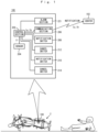
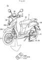
- FIG. 1 shows a top view of the leaning vehicle 2, and a block diagram of the leaning-vehicle-overturn-notification-system 100.
- FIG. 2 is a state transition diagram of the leaning-vehicle-overturn-notification-system 100.
- the leaning vehicle 2 is a vehicle that leans into turns.
- the leaning vehicle 2 is not particularly limited, and is, for example, a straddled vehicle such as a motorcycle or a motor tricycle.
- the term “frontward direction” refers to the direction of travel of the leaning vehicle 2 in an upright state.
- the term “backward direction” refers to the opposite direction to the direction of travel of the leaning vehicle 2 in an upright state.
- the terms “rightward direction” and “leftward direction” refer to the rightward direction and the leftward direction, respectively, when taking a rider who straddles the leaning vehicle 2 in an upright state as a reference.
- the terms “upward direction” and “downward direction” refer to the upward direction and the downward direction, respectively, when taking a rider who straddles the leaning vehicle 2 in an upright state as a reference.
- the leaning vehicle 2 includes the leaning-vehicle-overturn-notification-system 100.
- the leaning-vehicle-overturn-notification-system 100 is a system that notifies overturn occurrence information Ia which indicates that the leaning vehicle 2 changed from a travelling state Q1 (see FIG. 2 ) to an overturned state Q2 (see FIG. 2 ) to outside of the leaning vehicle 2 by radio communication.
- the term "outside of the leaning vehicle 2" is not particularly limited, and for example, refers to a center 102.
- the center 102 dispatches assistance to the rider of the leaning vehicle 2 based on the overturn occurrence information Ia.
- an overturn notification state q a state of notification of the overturn occurrence information Ia is referred to as an "overturn notification state q" (see FIG. 2 ).
- a non-notification state q1 (see FIG. 2 )
- a notification preparatory state q2 (see FIG. 2 )
- a notification completed state q3 (see FIG. 2 ) that are described later exist in the overturn notification state q.
- the leaning-vehicle-overturn-notification-system 100 includes a control section 202, a sensor 204, a communication section 206, notification switches 208 and 210, cancel switches 212 and 214 and an alarm section 221.
- the sensor 204 acquires determination base information I1 that is used for making an overturn determination and a notification determination at the control section 202 as described later.
- the overturn determination is a determination as to whether or not the leaning vehicle 2 changed from the travelling state Q1 to the overturned state Q2.
- the notification determination is a determination that, in a case where the leaning vehicle 2 changed from the travelling state Q1 to the overturned state Q2, determines whether or not it is necessary to notify the overturn occurrence information Ia to the center 102 by radio communication.
- the sensor 204 is not particularly limited, and for example is a speed sensor and a leaning determination sensor.
- the speed sensor measures the speed of the leaning vehicle 2.
- the leaning determination sensor is a sensor that outputs a leaning determination result that shows whether or not, when the leaning vehicle 2 is viewed from the frontward area, an angle (leaning angle) that is formed by a center line of the leaning vehicle 2 and the vertical direction is greater than a prescribed value.
- the prescribed value is a value that is defined according to the respective methods for determining an overturn which are described later, and therefore is a value that differs for each overturn determination method.
- the determination base information I1 is, for example, the speed of the leaning vehicle 2 and a leaning determination result.
- the sensor 204 may include a sensor other than a speed sensor and a leaning determination sensor.
- a sensor other than a speed sensor and a leaning determination sensor is not particularly limited, and for example is an acceleration sensor.
- An acceleration sensor measures the acceleration of the leaning vehicle 2. In this case the acceleration is also included in the determination base information I1.
- the control section 202 determines whether or not the leaning vehicle 2 changed from the travelling state Q1 to the overturned state Q2, based on the determination base information I1 that is output thereto from the sensor 204 (overturn determination). In addition, based on the determination base information I1 that is output thereto from the sensor 204, the control section 202 determines whether or not it is necessary to notify the overturn occurrence information Ia to the center 102 by radio communication (notification determination).
- the control section 202 performs the notification determination after the overturn determination.
- the control section 202 determines the size of the impact of overturning based on the speed of the leaning vehicle 2 that the sensor 204 measured. If the impact of overturning is relatively large, the control section 202 determines that notification of the overturn occurrence information Ia is necessary.
- the control section 202 determines that notification of the overturn occurrence information Ia is unnecessary.
- Various determination methods that are already known can be applied as the methods used to perform the overturn determination and the notification determination. Further, novel determination methods that are not publicly known may be applied as the methods used to perform the overturn determination and the notification determination.
- a definition of the travelling state Q1 and a definition of the overturned state Q2 are not particularly limited, and the definitions differ depending on the overturn determination method.
- the conditions for determining that notification of the overturn occurrence information Ia is necessary are also not particularly limited, and the conditions differ depending on the notification determination method.
- the overturn occurrence information Ia is not notified in the travelling state Q1.
- the overturn notification state q in which the overturn occurrence information Ia is not notified is referred to as "non-notification state q1" (see FIG. 2 ).
- the control section 202 determines that the leaning vehicle 2 changed from the travelling state Q1 to the overturned state Q2 and also determines that notification of the overturn occurrence information Ia is necessary, the control section 202 conducts preparations for notifying the overturn occurrence information Ia to the center 102.
- a fact that the control section 202 determines that the leaning vehicle 2 changed from the travelling state Q1 to the overturned state Q2 is referred to as an "overturn change determination”.
- a fact that the control section 202 determines that notification of the overturn occurrence information Ia is necessary is referred to as a "notification necessary determination”.
- the control section 202 waits for a predetermined time period Ta (for example, 30 seconds) from the time of making the notification necessary determination before outputting the overturn occurrence information Ia to the communication section 206 that is described later.
- a predetermined time period Ta for example, 30 seconds
- An overturn notification state q in which the control section 202 is waiting before outputting the overturn occurrence information Ia is referred to as "notification preparatory state q2" (see FIG. 2 ).
- the control section 202 outputs the overturn occurrence information Ia to the communication section 206 that is described later.
- the communication section 206 receives the overturn occurrence information Ia that was output from the control section 202, the communication section 206 transmits the overturn occurrence information Ia to the center 102.
- an overturn notification state q in which the overturn occurrence information Ia has been notified is referred to as "notification completed state q3" (see FIG. 2 )
- the alarm section 221 is a section that, by radiating a light or generating a sound when the leaning vehicle 2 has overturned, notifies people in the area around the leaning vehicle 2 that the leaning vehicle 2 has overturned.
- the alarm section 221 is, for example, a front light, a tail light, a license plate light, indicators and a horn.
- the front light, tail light, license plate light and indicators flash or light up when the leaning vehicle 2 has overturned.
- the horn emits a sound continuously or intermittently when the leaning vehicle 2 has overturned.
- the notification switches 208 and 210 are function switches for causing the leaning-vehicle-overturn-notification-system 100 to notify the overturn occurrence information Ia to the center 102 when operated by the rider or a third party.
- the notification switches 208 and 210 are operated by the rider or a third party, even if the control section 202 has not made an overturn change determination and a notification necessary determination, the leaning-vehicle-overturn-notification-system 100 notifies the overturn occurrence information Ia to the center 102.
- the notification switch 208 and the notification switch 210 are disposed at different positions from each other in the leaning vehicle 2.
- the cancel switches 212 and 214 are function switches for cancelling the preparation by the leaning-vehicle-overturn-notification-system 100 for notifying the overturn occurrence information Ia to the center 102 when operated by the rider or a third party present in the area around the leaning vehicle 2. Specifically, even when in the notification preparatory state q2, there are times when the rider does not want the leaning-vehicle-overturn-notification-system 100 to notify the overturn occurrence information Ia to the center 102. Therefore, before outputting the overturn occurrence information Ia to the communication section 206, the control section 202 waits for the predetermined time period Ta after making a notification necessary determination.
- the control section 202 does not output the overturn occurrence information Ia to the communication section 206. That is, the leaning-vehicle-overturn-notification-system 100 cancels the preparation for notification of the overturn occurrence information Ia.
- the cancel switches 212 and 214 are also function switches for cancelling notification of the overturn occurrence information Ia in a case where the leaning-vehicle-overturn-notification-system 100 notified the overturn occurrence information Ia to the center 102. Specifically, even in the notification completed state q3, there are times when the rider wants to cancel the notification of the overturn occurrence information Ia that was notified to the center 102. Therefore, after the overturn occurrence information Ia has been notified to the center 102, if the cancel switch 212 or 214 is operated by the rider or a third party, the control section 202 transmits notification cancellation information Ib to the center 102 through the communication section 206.
- the leaning-vehicle-overturn-notification-system 100 cancels the notification of the overturn occurrence information Ia that was notified.
- the cancel switch 212 and the cancel switch 214 are disposed at different positions from each other in the leaning vehicle 2.
- FIG. 3 is a flowchart of operations that the control section 202 executes.
- the present processing is started, for example, when an electric current is fed by an ignition power source of the leaning vehicle 2, and electric power is supplied to the leaning-vehicle-overturn-notification-system 100.
- the overturn notification state q when the present processing starts is the non-notification state q1.
- the control section 202 determines whether or not the notification switch 208 or the notification switch 210 is switched on (step S1). If the notification switch 208 or the notification switch 210 is switched on (Yes), the present processing proceeds to step S2. If the notification switch 208 and the notification switch 210 are not switched on (No), the present processing proceeds to step S7.
- the control section 202 In a case where the notification switch 208 or the notification switch 210 is switched on (Yes in step S1), the control section 202 notifies the overturn occurrence information Ia to the center 102 through the communication section 206 (step S2). As a result, the overturn notification state q changes from the non-notification state q1 to the notification completed state q3. In addition, the control section 202 starts measurement of a predetermined time period Tb (for example, 5 minutes) (step S3).
- Tb for example, 5 minutes
- step S3 after the predetermined time period Tb passes from step S3, even if the rider switches on the cancel switch 212 or the cancel switch 214, notification of the overturn occurrence information Ia that was notified to the center 102 by the leaning-vehicle-overturn-notification-system 100 is not cancelled. At such time, assistance is dispatched to the rider.
- step S4 determines whether or not the predetermined time period Tb has elapsed from step S3 (step S4). If the predetermined time period Tb elapsed (Yes), the present processing ends. In this case, the center 102 dispatches assistance to the rider. If the predetermined time period Tb has not elapsed (No), the present processing proceeds to step S5.
- step S4 determines whether or not the cancel switch 212 or the cancel switch 214 has been switched on (step S5). If the cancel switch 212 or the cancel switch 214 has been switched on (Yes), the present processing proceeds to step S6. If the cancel switch 212 and the cancel switch 214 have not been switched on (No), the present processing returns to step S4.
- step S5 If the cancel switch 212 or the cancel switch 214 has been switched on (Yes in step S5), the control section 202 notifies the notification cancellation information Ib (see FIG. 1 ) to the center 102 through the communication section 206 (step S6). By this means, the notification of the overturn occurrence information Ia that was notified to the center 102 by the leaning-vehicle-overturn-notification-system 100 is cancelled. Thereafter, the present processing ends.
- the control section 202 acquires the determination base information I1 from the sensor 204 (step S7). Based on the determination base information I1, the control section 202 determines whether or not the leaning vehicle 2 changed from the travelling state Q1 to the overturned state Q2 (step S8; overturn determination). If the leaning vehicle 2 changed to the overturned state Q2 (Yes), the present processing proceeds to step S9. If the leaning vehicle 2 has not changed to the overturned state Q2 (No), the present processing returns to step S1.
- step S9 the control section 202 determines whether or not it is necessary for the leaning-vehicle-overturn-notification-system 100 to notify the overturn occurrence information Ia to the center 102 (step S9; notification determination).
- step S9 for example, the control section 202 determines the size of the impact of overturning. In a case where the impact of overturning is relatively large, the control section 202 determines that notification of the overturn occurrence information Ia is necessary (Yes).
- the overturn notification state q changes from the non-notification state q1 to the notification preparatory state q2. In this case, the present processing proceeds to step S10. In a case where the impact of overturning is relatively small, the control section 202 determines that notification of the overturn occurrence information Ia is unnecessary (No). In this case, the present processing returns to step S1.
- step S10 the control section 202 activates the alarm section 221 (step S10).
- the control section 202 causes the front light, tail light, license plate lamp or indicators to flash, and also causes the horn to generate a sound.
- the control section 202 starts measurement of a predetermined time period Ta (for example, 30 seconds) (step S 11).
- the control section 202 determines whether or not the predetermined time period Ta has passed from step S11 (step S12). If the predetermined time period Ta has not passed (No), the present processing proceeds to step S13. If the predetermined time period Ta has passed (Yes), the present processing proceeds to step S14.
- step S13 the control section 202 determines whether or not the cancel switch 212 or the cancel switch 214 has been switched on. If the cancel switch 212 or the cancel switch 214 has been switched on (Yes), the preparation being performed by the leaning-vehicle-overturn-notification-system 100 for notifying the overturn occurrence information Ia to the center 102 is cancelled. That is, the overturn occurrence information Ia is not notified to the center 102. Thereafter, the present processing ends. If the cancel switch 212 and the cancel switch 214 have not been switched on (No), the present processing returns to step S12.
- step S12 If the predetermined time period Ta has passed (Yes in step S12), the control section 202 notifies the overturn occurrence information Ia to the center 102 through the communication section 206 (step S14).
- the overturn notification state q changes from the notification preparatory state q2 to the notification completed state q3.
- control section 202 starts measurement of the predetermined time period Tb (step S15).
- the control section 202 determines whether or not the predetermined time period Tb has passed from the time of step S15 (step S16). If the predetermined time period Tb has passed (Yes), the present processing ends. In this case, the center 102 dispatches assistance to the rider. If the predetermined time period Tb has not passed (No), the present processing proceeds to step S17.
- step S16 determines whether or not the cancel switch 212 or the cancel switch 214 has been switched on (step S17). If the cancel switch 212 or the cancel switch 214 has been switched on (Yes), the present processing proceeds to step S18. If the cancel switch 212 and the cancel switch 214 have not been switched on (No), the present processing returns to step S16.
- step S17 If the cancel switch 212 or the cancel switch 214 has been switched on (Yes in step S17), the control section 202 notifies the notification cancellation information Ib to the center 102 through the communication section 206 (step S18). By this means, notification of the overturn occurrence information Ia that was notified to the center 102 by the leaning-vehicle-overturn-notification-system 100 is cancelled. Thereafter, the present processing ends.
- FIG. 4 is a left side view of the leaning vehicle 2.
- FIG. 5 is a top view of the leaning vehicle 2.
- a first member is disposed further forward than a second member
- the term "a first member is disposed further forward than a second member” indicates the following state. That is, the first member is disposed in front of a plane orthogonal to the front-back direction which passes through the front end of the second member. In this case, the first member and the second member may or may not be aligned in the front-back direction. This definition also applies to directions other than the front-back direction.
- a first member is disposed in front of a second member
- the term "a first member is disposed in front of a second member” indicates the following state. That is, at least one part of the first member is disposed within a region that the second member will pass through if the second member translates in the frontward direction. Hence, the entire first member may fit within a region that the second member will pass through if the second member translates in the frontward direction, or the first member may protrude from a region that the second member will pass through if the second member translates in the frontward direction. In this case, the first member and the second member are aligned in the front-back direction. This definition also applies to directions other than the front-back direction.
- the term "upper portion” of a component means the portion of the component that is located above the center of the component in the up-down direction.
- the term “lower portion” of a component means the portion of the component that is located below the center of the component in the up-down direction.
- the term "front portion” of a component means the portion of the component that is located in front of the center of the component in the front-back direction.
- the term “back portion” of a component means the portion of the component that is located behind the center of the component in the front-back direction.
- the term “right portion” of a component means the portion of the component that is located to the right of the center of the component in the left-right direction.
- left portion of a component means the portion of the component that is located to the left of the center of the component in the left-right direction.
- top end of a component means the end of the component in the upward direction.
- bottom end of a component means the end of the component in the downward direction.
- front end of a component means the end of the component in the frontward direction.
- back end of a component means the end of the component in the backward direction.
- right end of a component means the end of the component in the rightward direction.
- left end of a component means the end of the component in the leftward direction.
- top end portion means the top end and the vicinity of the top end of the component.
- bottom end portion of a component means the bottom end and the vicinity of the bottom end of the component.
- front end portion means the front end and the vicinity of the front end of the component.
- back end portion means the back end and the vicinity of the back end of the component.
- right end portion means the right end and the vicinity of the right end of the component.
- left end portion means the left end and the vicinity of the left end of the component.
- component means the leaning vehicle 2 and a member constituting a part of the leaning vehicle 2.
- the leaning vehicle 2 is a naked-type motorcycle.
- the leaning vehicle 2 includes the vehicle body 4, a steerable wheel 6, a handle 8, a steering shaft 9, a front fork 10, a drive wheel 12, a power unit 34, a power unit 34, a swing arm 36, a front light unit 38, a tank 40, a seat 42, a rear fender 46, a tail light unit 48, a license plate light unit 50, a meter unit 80 (see FIG. 5 ) and a switch unit 219.
- the vehicle body 4 leans to the left when the leaning vehicle 2 turns left, and leans to the right when the leaning vehicle 2 turns right.
- the vehicle body 4 includes a frame 30 and a stay 32.
- the frame 30 includes a main frame 30a, a head pipe 30b and a seat rail 30c.
- the head pipe 30b has a cylindrical shape. In the leaning vehicle 2 in an upright state, the central axis of the head pipe 30b inclines slightly relative to the vertical direction so that the top end of the central axis of the head pipe 30b is located further backward than the bottom end of the central axis of the head pipe 30b.
- the main frame 30a is connected to the head pipe 30b.
- the main frame 30a extends in the backward direction from the head pipe 30b. Further, the main frame 30a bends in the downward direction at the back end portion of the main frame 30a.
- the seat rail 30c is connected to the main frame 30a.
- the seat rail 30c extends linearly rearward and upward from the portion at which the main frame 30a bends.
- a stay 32 is attached to the head pipe 30b.
- the stay 32 is disposed in front of the head pipe 30b.
- attached means that two components are integrated in a state in which the components can be separated without damage to the members.
- the swing arm 36 is attached to the main frame 30a.
- the swing arm 36 extends in the rearward direction from the main frame 30a below the seat rail 30c.
- the swing arm 36 can swing in the up-down direction around a connecting portion between the swing arm 36 and the main frame 30a.
- the swing arm 36 may be attached to the engine instead of being attached to the main frame 30a.
- the steering shaft 9 is inserted into the head pipe 30b.
- the handle 8 is attached through a bracket to the top end portion of the steering shaft 9.
- the front fork 10 is attached through a bracket to the bottom end portion of the steering shaft 9.
- the steerable wheel 6 is the front wheel of the leaning vehicle 2.
- the steerable wheel 6 is attached to the bottom end portion of the front fork 10 so as to be capable of rotating around an axle shaft.
- the rider can steer the steerable wheel 6 by operating the handle 8. Specifically, when the leaning vehicle 2 is viewed from upward area, when the rider turns the handle 8 clockwise, the steerable wheel 6 is caused to turn clockwise.
- the vehicle body 4 leans to the right and the leaning vehicle 2 turns the right. Further, when the leaning vehicle 2 is viewed from upward area, when the rider turns the handle 8 counterclockwise, the steerable wheel 6 is caused to turn counterclockwise.
- the vehicle body 4 leans to the left, and the leaning vehicle 2 turns the left.
- the drive wheel 12 is the rear wheel of the leaning vehicle 2.
- the drive wheel 12 is attached to the back end portion of the swing arm 36 so as to be capable of rotating around the axle shaft.
- the front light unit 38 is a lighting device that radiates light in front of the leaning vehicle 2.
- the front light unit 38 is attached to the stay 32. By this means, the front light unit 38 is disposed at the front end portion of the vehicle body 4.
- the tank 40 stores fuel such as gasoline.
- the tank 40 is attached to the main frame 30a.
- the tank 40 is disposed at an upper portion of the vehicle body 4.
- the seat 42 is attached to the seat rail 30c.
- the seat 42 is disposed behind the tank 40 at the upper portion of the vehicle body 4.
- the power unit 34 generates a driving force for running the leaning vehicle 2.
- the driving force which the power unit 34 generates is transmitted to the drive wheel 12.
- the power unit 34 is not particularly limited, and for example may be a combination of an engine and a transmission or may be a combination of a motor and a transmission.
- the power unit 34 is attached to the main frame 30a.
- the power unit 34 is disposed below the tank 40.
- the tail light unit 48 is a lighting device that radiates light behind the leaning vehicle 2.
- the tail light unit 48 is attached through a bracket (not illustrated) to the back end portion of the seat rail 30c.
- the rear fender 46 extends backward and downward from the vicinity of the back end portion of the seat rail 30c.
- a holding section 47 is provided in the vicinity of the bottom end portion of the rear fender 46.
- a license plate (not illustrated) is attached to the holding section 47.
- the license plate light unit 50 is a lighting device that, by radiating light in the downward direction, illuminates the license plate attached to the holding section 47.
- the license plate light unit 50 extends in the backward direction from the vicinity of the center in the up-down direction of the rear fender 46.
- the meter unit 80 is a measuring instrument that displays information, such as the speed, toward the rider.
- the meter unit 80 is disposed in front of the handle 8 in the leaning vehicle 2.
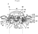
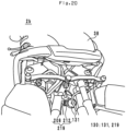
- FIG. 6 is a perspective view of the handle 8 and the meter unit 80 as viewed from a rearward and upward area.
- the handle 8 includes a handlebar 59, a right handle grip 60, a left handle grip 62, right switch boxes 64 and 65, and left switch boxes 66 and 67.
- the handlebar 59 is a cylindrical member that extends in the left-right direction. However, the right portion of the handlebar 59 is drawn by a small amount in the upward and backward direction from the center in the left-right direction of the handlebar 59. Further, the left portion of the handlebar 59 is drawn by a small amount in the upward and backward direction from the center in the left-right direction of the handlebar 59.
- the left handle grip 62 is a circular cylindrical member having a central axis that extends in the left-right direction.
- the left end portion of the handlebar 59 is inserted into the left handle grip 62 from an opening at the right end of the left handle grip 62.
- the left handle grip 62 is disposed at the left end portion of the handlebar 59.
- the left handle grip 62 is fixed to the handlebar 59, and cannot rotate with respect to the handlebar 59. The rider holds the left handle grip 62 with their left hand.
- the left switch boxes 66 and 67 are attached to the handlebar 59.
- the left switch boxes 66 and 67 are disposed at positions that are located further leftward than the center in the left-right direction of the leaning vehicle 2 in an upright state, and to the right of the left handle grip 62.
- the left switch box 66 is disposed to the right of the left handle grip 62 so as to be adjacent to the left handle grip 62.
- the left switch box 67 is disposed to the right of the left switch box 66 so as to be adjacent to the left switch box 66.
- the left switch boxes 66 and 67 are arranged in a row in the rightward direction from the right end of the left handle grip 62.
- adjacent means that two components adjoin each other in a contacting or connected state.
- in a row means that two or more components are arranged in one row, and adjoining components among the two or more components are contacting or connected with each other.
- Switches are disposed in the left switch boxes 66 and 67.
- the switches that are disposed in the left switch boxes 66 and 67 are not particularly limited, and for example are a passing light switch, a headlight up/down changeover switch, a direction indicator switch and a horn switch.
- the right handle grip 60 includes a grip section 60a and a detection section 60b.
- the grip section 60a is a circular cylindrical member having a central axis that extends in the left-right direction.
- the right end portion of the handlebar 59 is inserted into the grip section 60a from an opening in the left end of the grip section 60a.
- the grip section 60a is disposed at the right end portion of the handlebar 59.
- the grip section 60a can rotate around the central axis of the handlebar 59.
- the detection section 60b is disposed to the left of the grip section 60a so as to be adjacent to the grip section 60a.
- the detection section 60b includes a built-in sensor that detects a rotation angle from an initial position of the grip section 60a.
- the initial position of the grip section 60a is the position of the grip section 60a when the rider is not touching the grip section 60a.
- the detection section 60b outputs the detected angle as an electrical signal to an ECU (electric control unit; not illustrated) through electrical wiring 75.
- the ECU controls the output of the power unit 34 based on the electrical signal. That is, the rider can adjust the output of the power unit 34 by rotating the grip section 60a with their right hand.
- the right handle grip 60 has been described by taking as an example the leaning vehicle 2 in which an electronic control throttle mechanism is applied.
- a mechanical control throttle mechanism may be applied in the leaning vehicle 2.
- the grip section 60a and the power unit 34 are mechanically connected through a cable.
- a first end of the cable is physically connected to the grip section 60a in the detection section 60b.
- a second end of the cable is physically connected to the power unit 34.
- the grip section 60a is positioned at the initial position when the rider is not touching the grip section 60a. In this case, the output of the power unit 34 is relatively small.
- the cable is drawn towards the grip section 60a from the power unit 34. As a result, the output of the power unit 34 becomes relatively larger.
- the right switch boxes 64 and 65 are attached to the handlebar 59.
- the right switch boxes 64 and 65 are disposed at positions that are located further rightward than the center in the left-right direction of the leaning vehicle 2 in an upright state, and to the left of the right handle grip 60.
- the right switch box 64 is disposed to the left of the detection section 60b so as to be adjacent to the detection section 60b.
- the right switch box 65 is disposed to the left of the right switch box 64 so as to be adjacent to the right switch box 64.
- the right switch boxes 64 and 65 are arranged in a row in the leftward direction from the left end of the right handle grip 60.
- a switch is disposed in the right switch box 64.
- the switch disposed in the right switch box 64 is not particularly limited, and for example is an engine stop switch or a starter switch.
- a plane perpendicular to the left-right direction that includes the left end of the right switch box 65 is defined as a "plane SR" (see FIG. 5 and FIG. 6 ).
- the right switch box 65 is the right switch box that is positioned furthest to the left among the right switch boxes 64 and 65.
- a plane perpendicular to the left-right direction that includes the right end of the left switch box 67 is defined as a "plane SL" (see FIG. 5 and FIG. 6 ).
- the left switch box 67 is the left switch box that is positioned furthest to the right among the left switch boxes 66 and 67.
- the region located between the plane SR and the plane SL is defined as a "center region AC".
- a switch unit 220 includes the notification switch 210, the cancel switch 214 (one example of a second cancel switch), and a switch cover 218 (one example of a second cancel switch cover) (see FIG. 6 ).
- the switch unit 220 is disposed in the right switch box 65. Hence, the switch unit 220 is disposed outside the center region AC.
- the description "the switch unit 220 is disposed outside the center region AC" means that the entire switch unit 220 is disposed outside the center region AC.
- the notification switch 210 and the cancel switch 214 are aligned in that order from the up to the down on the back surface of the right switch box 65.
- the notification switch 210 and the cancel switch 214 are not particularly limited, and, for example, are push buttons.
- the notification switch 210 and the cancel switch 214 have operation surfaces S210 and S214, respectively, that the rider touches when operating the notification switch 210 and the cancel switch 214.
- the characters "CALL” are written on the operation surface S210.
- the characters "CANCEL” or “STOP” are written on the operation surface S214.
- the operation surfaces S210 and S214 direct backward.
- the switch cover 218 is a protective cover for the notification switch 210 and the cancel switch 214.
- the switch cover 218 is disposed in the right switch box 65. In the leaning vehicle 2 that is in an upright state, the switch cover 218 can rotate around a top end portion thereof within a plane perpendicular to the left-right direction. By this means, the switch cover 218 can assume a covering state in which the switch cover 218 covers the notification switch 210 and the cancel switch 214, and a non-covering state in which the switch cover 218 does not cover the notification switch 210 and the cancel switch 214. In the covering state, the rider cannot operate (that is, switch on) the notification switch 210 and the cancel switch 214. In the non-covering state, the rider can operate (that is, switch on) the notification switch 210 and the cancel switch 214.
- the meter unit 80 includes meters 135 such as a speedometer, a tachometer, a fuel gauge and a water temperature gauge.
- the meter unit 80 is disposed in front of the handle 8 in the leaning vehicle 2.
- the meters 135 may be meters that have a needle and a dial, or may be meters that are displayed on a liquid crystal panel or an organic EL panel. Further, the meters 135 may include a meter having a needle and a dial and meters that are displayed on a liquid crystal panel and an organic EL panel.
- the meters 135 are meters which are displayed on a liquid crystal panel.
- FIG. 7 is a perspective view of the tail light unit 48.
- FIG. 8 is a perspective view of the tail light unit 48 in a state in which the tail light unit 48 has been detached from the vehicle body 4.
- the tail light unit 48 includes a tail light 89 and the switch unit 219.
- the tail light 89 radiates light in the backward direction.
- the tail light 89 is a lighting device that includes a tail lamp and a brake lamp.
- the tail light 89 radiates light in the backward direction as the alarm section 221 when the leaning vehicle 2 overturns.
- the tail light 89 is attached to the back end portion of the seat rail 30c.
- the seat rail 30c extends in the front-back direction at the center in the left-right direction of the vehicle body 4 (see FIG. 5 ). Therefore, the tail light 89 is disposed at the center in the left-right direction of the vehicle body 4. That is, the tail light 89 is disposed within the center region AC (see FIG. 5 ).
- the description "a component is disposed within the center region AC" means that at least one part of the component is disposed within the center region AC.
- the tail light 89 includes a light source (not illustrated), a drive circuit (not illustrated), a cover 90, a lens 91, electrical wiring 92 and a connector 93 (see FIG. 8 ).
- the light source emits light upon being supplied with electric power.
- the light source is not particularly limited, and for example is a HID lamp, a halogen lamp or an LED.
- the drive circuit is a circuit board that controls the light emission of the light source. Note that the drive circuit may be disposed in the vehicle body 4 instead of in the tail light 89.
- the cover 90 is disposed at a front portion of the tail light 89.
- the lens 91 is disposed at a back portion of the tail light 89.
- the lens 91 is manufactured using a translucent material such as resin or glass.
- the cover 90 and lens 91 form a hollow container, and house the light source and the drive circuit. Light that the light source radiates is transmitted through the lens 91 and travels to behind the leaning vehicle 2.
- the electrical wiring 92 is electrically connected to the drive circuit and the light source, and is led out in the frontward direction from the cover 90.
- the connector 93 is disposed at the front end of the electrical wiring 92.
- the connector 93 is connected to a connector (not illustrated) for electrical wiring that is disposed in the vehicle body 4. By this means, electric power is supplied to the tail light 89.
- the switch unit 219 includes a notification switch 208 (one example of a first notification switch), the cancel switch 212 (one example of a first cancel switch), and a switch cover 216 (first cancel switch cover).
- the switch unit 219 is disposed on the bottom face of the tail light 89.
- the switch unit 219 is disposed within the center region AC.
- the entire switch unit 219 is disposed within the center region AC.
- the notification switch 208 and the cancel switch 212 are arranged side by side in that order from the back to the front on the bottom face of the tail light 89.
- the notification switch 208 and the cancel switch 212 are not particularly limited, and for example are push buttons. Therefore, the notification switch 208 and the cancel switch 212 have operation surfaces S208 and S212, respectively, that the rider touches when operating the notification switch 208 and the cancel switch 212.
- the operation surfaces S208 and S212 direct downward.
- the switch cover 216 is a protective cover for the notification switch 208 and the cancel switch 212.
- the switch cover 216 is disposed on the bottom face of the tail light 89. In the leaning vehicle 2 that is in an upright state, the switch cover 216 can rotate around a front end portion thereof within a plane perpendicular to the left-right direction. By this means, the switch cover 216 can assume a covering state in which the switch cover 216 covers the notification switch 208 and the cancel switch 212, and a non-covering state in which the switch cover 216 does not cover the notification switch 208 and the cancel switch 212. In the covering state, the rider cannot operate (that is, switch on) the notification switch 208 and the cancel switch 212. In the non-covering state, the rider can operate (that is, switch on) the notification switch 208 and the cancel switch 212.
- the notification switch 208 and the cancel switch 212 are connected to the electrical wiring 92 through an electric circuit that is inside the tail light unit 48.
- the notification switch 208 and the cancel switch 212 are electrically connected to the control section 202 (see FIG. 1 ) of the leaning-vehicle-overturn-notification-system 100 through the electrical wiring 92 and electrical wiring (not illustrated) that is disposed in the vehicle body 4.
- the tail light unit 48 is an electrical parts assembly with a cancel switch that can be detachably attached to the vehicle body 4 in a state in which a plurality of parts that include the notification switch 208, the cancel switch 212 and the tail light 89 (an example of at least one electrical part that is different from the first cancel switch) are combined.
- the term "can be detachably attached” means that two components can be integrated and separated without causing damage to members.
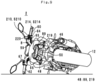
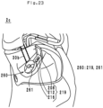
- FIG. 9 is a view of the leaning vehicle 2 in an overturned state as viewed from the backward area.
- FIG. 9 an example is illustrated in which the leaning vehicle 2 overturned in a manner such that the left side face thereof directs downward.
- the tail light 89 Since it is necessary for the tail light 89 to be visible from a following vehicle, the tail light 89 is disposed at a position that is visible from the backward area in the leaning vehicle 2 in an upright state (see FIG. 4 ). Therefore, as illustrated in FIG. 9 , the tail light 89 is disposed at a position that is also visible from backward area in the leaning vehicle 2 in an overturned state. Further, the switch unit 219 is disposed on the bottom face of the tail light 89 (see FIG. 7 ). Therefore, as illustrated in FIG. 9 , the switch unit 219 is also disposed at a position that is visible from the backward area in the leaning vehicle 2 in an overturned state.
- the switch unit 219 is disposed at a position that is visible in one or more horizontal directions in the leaning vehicle 2 in an overturned state.
- the tail light 89 and the switch unit 219 are disposed at positions which can be visually recognized simultaneously in the leaning vehicle 2 in an overturned state.
- the tail light 89 and the switch unit 219 are in close proximity to each other. Therefore, in the leaning vehicle 2 in an overturned state, the tail light 89 and the switch unit 219 are visually recognized at the same time by the rider who operates the notification switch 208 or the cancel switch 212.
- horizontal direction typically refers to a direction that is perpendicular to the direction in which the force of gravity acts, and includes the frontward direction, backward direction, rightward direction and leftward direction.
- horizontal direction also includes a direction that inclines relative to a direction that is perpendicular to the direction in which the force of gravity acts. This is because there is a possibility that a center plane of the leaning vehicle 2 in an overturned state will incline relative to the horizontal direction.
- center plane of the leaning vehicle 2 refers to a plane that includes the center in the left-right direction of the leaning vehicle 2 in an upright state and is also perpendicular to the left-right direction.
- the range of an angle (that is, an angle of elevation) formed by the "horizontal direction” and a plane perpendicular to the direction in which the force of gravity acts is -45° or more to not more than 45°.
- the operation surfaces S208 and S212 of the notification switch 208 and the cancel switch 212 direct downward in the leaning vehicle 2 that is in an upright state (see FIG. 7 ). Accordingly, the operation surfaces S208 and S212 direct in the horizontal direction in the leaning vehicle that is in an overturned state.
- the color of the notification switch 208 and the cancel switch 212 is not particularly limited, and for example is red. Further, the color of the switch cover 216 is not particularly limited, and for example is transparent. In addition, the color of the bottom face of the tail light 89 is not particularly limited, and for example is black. Thus, the color of the notification switch 208 and the cancel switch 212 differ from the color of a member (the bottom face of the tail light 89) located in the area around the notification switch 208 and the cancel switch 212. Further, since the color of the switch cover 216 is transparent, even in the covering state, the rider and a third party present in the area around the leaning vehicle 2 can visually recognize the notification switch 208 and the cancel switch 212.
- the right portion of the handlebar 59 is a position that the rider who straddles the leaning vehicle 2 can visually recognize.
- the switch unit 220 is disposed at the right portion of the handlebar 59.
- the switch unit 220 is disposed at a position that the rider who straddles the leaning vehicle 2 can visually recognize.
- the right portion of the handlebar 59 is extended upward from the center in the left-right direction of the vehicle body 4. Therefore, the right portion of the handlebar 59 is disposed at a position that is visible from the backward area in the leaning vehicle 2 in an upright state. Further, as illustrated in FIG. 9 , the right portion of the handlebar 59 is disposed at a position that is also visible from the backward area in the leaning vehicle 2 in an overturned state.
- the right switch box 65 is disposed at the right portion of the handlebar 59. Therefore, the right switch box 65 is disposed at a position that is also visible from the backward area in the leaning vehicle 2 in an overturned state.
- the switch unit 220 is disposed on the back surface of the right switch box 65. Therefore, the switch unit 220 is disposed at a position that is also visible from the backward area in the leaning vehicle 2 in an overturned state. By this means, the switch unit 220 is disposed at a position that is visible in one or more horizontal directions in the leaning vehicle 2 in an overturned state.
- the operation surfaces S210 and S214 of the notification switch 210 and the cancel switch 214 direct backward in the leaning vehicle 2 in an upright state. Accordingly, in the leaning vehicle in an overturned state, the operation surfaces S210 and S214 direct in the horizontal direction (more exactly, in the rearward direction).
- the color of the notification switch 210 and the cancel switch 214 is not particularly limited, and for example is red. Further, the color of the switch cover 218 is not particularly limited, and for example is black. In addition, the color of the right switch box 65 is not particularly limited, and for example is black. Thus, the color of the notification switch 210 and the cancel switch 214 differ from the color of a member (the back surface of the right switch box 65) located in the area around the notification switch 210 and the cancel switch 214.
- the leaning vehicle 2 in the leaning vehicle 2 in an overturned state there is a high probability that the rider can quickly operate the cancel switch 212.
- the leaning vehicle 2 in an overturned state will assume a posture in which the right side face or the left side face thereof directs downward.
- the leaning vehicle 2 overturns there is a high probability that the rider will be on the ground. At such time, the rider can visually recognize the front face, rear face, top surface or undersurface in the leaning vehicle 2 in an upright state.
- the switch unit 219 is disposed at a position that is visible in one or more horizontal directions in the leaning vehicle 2 in an overturned state.
- the switch unit 219 is disposed within the center region AC.
- the center region AC is a region that, in the leaning vehicle 2 in an upright state, is in the vicinity of the center in the left-right direction. Therefore, the center region AC is a region for which the probability of being concealed below the vehicle body 4 is low in the leaning vehicle 2 in an overturned state.
- the switch unit 219 is disposed at a position which is easy for the rider to visually recognize and is also easy for the rider to operate in the leaning vehicle 2 in an overturned state.
- the switch unit 219 is disposed at a position which is easy for the rider to visually recognize and is also easy for the rider to operate in the leaning vehicle 2 in an overturned state.
- the switch unit 220 is not necessarily essential. However, it is preferable to combine the switch unit 219 of the leaning vehicle 2 with the switch unit 220.
- the notification switch 210 and the cancel switch 214 have the same structure as the notification switch and the cancel switch that have already been proposed in the prior art, as is described in Non Patent Literature 1 also.
- the notification switch 210 and the cancel switch 214 are disposed close to the right handle grip 60. In a state in which the rider straddles the leaning vehicle 2 in an upright state, the rider can visually recognize the notification switch 210 and the cancel switch 214. Therefore, when the leaning vehicle 2 is travelling, the rider can recognize the positions of the notification switch 210 and the cancel switch 214.
- the rider can operate the notification switch 210 and the cancel switch 214.
- the notification switch 210 and the cancel switch 214 will be concealed below the vehicle body 4 if the leaning vehicle 2 overturns in a manner such that the right side face of the vehicle body 4 directs downward.
- the inventors of the present application conducted studies regarding disposing an additional left switch box to the right of the left switch box 67 so as to be adjacent to the left switch box 67, and disposing a notification switch and a cancel switch in the additional left switch box. By this means, even in a case where the leaning vehicle 2 overturns in a manner such that either the right side face or the left side face of the leaning vehicle 2 directs downward, there will be a cancel switch that is not concealed below the vehicle body 4. Taking into account such studies, the inventors of the present application investigated the idea of disposing the notification switch 208 and the cancel switch 212 at a position other than a position adjacent to the left switch box 67.
- the inventors of the present application disposed the switch unit 219 at a position that is within the center region AC, and is visible in one or more horizontal directions in the leaning vehicle 2 in an overturned state.
- the switch unit 220 is concealed below the vehicle body 4 in the leaning vehicle 2 in an overturned state, there is a high probability that the rider can quickly operate the cancel switch 212 of the switch unit 219.
- the notification switch 210 and the cancel switch 214 are disposed at positions at which the notification switch 210 and the cancel switch 214 are easy to operate when the leaning vehicle 2 is in an upright state.
- the notification switch 208 and the cancel switch 212 are disposed at positions which are easy for the rider to visually recognize in the leaning vehicle 2 in an overturned state.
- the notification switch 208 and the cancel switch 212 are disposed at positions at which the notification switch 208 and the cancel switch 212 are easy to operate in the leaning vehicle 2 in an overturned state.
- the routing of the electrical wiring is simplified. More specifically, the switch unit 219 is included in the tail light unit 48. By this means, it is possible to provide electrical wiring that connects the notification switch 208 and cancel switch 212 with the control section 202 within the electrical wiring 92 of the tail light unit 48.
- the leaning vehicle 2 may not include electrical wiring that connects the notification switch 208 and cancel switch 212 with the control section 202 that is separate from the electrical wiring 92 of the tail light 89. As a result, in the leaning vehicle 2, the routing of the electrical wiring is simplified.
- the switch unit 219. there is a higher probability that the rider can recognize the switch unit 219. More specifically, when the tail light 89 radiates light as the alarm section 221, the attention of the rider is drawn to the tail light 89.
- the tail light 89 and the switch unit 219 are disposed at positions that are visually recognizable at the same time in the leaning vehicle 2 in an overturned state. By this means, there is a higher probability that the rider can recognize the switch unit 219.
- the color of the switch cover 216 is transparent. Hence, even in a covering state, the rider can recognize the notification switch 208 and the cancel switch 212.
- the color of the notification switch 208 and the cancel switch 212 is different from the color of a member (bottom face of the tail light 89) positioned around the notification switch 208 and the cancel switch 212. Therefore, the rider can recognize the existence of the notification switch 208 and the cancel switch 212 by means of the color.
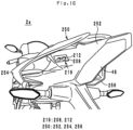
- FIG. 10 is a perspective view of the front light unit 38.
- FIG. 11 is a perspective view of the front light unit 38 in a state in which the front light unit 38 is detached from the vehicle body 4.
- the front light unit 38 includes a front light 119 and the switch unit 219.
- the front light 119 radiates light in the frontward direction.
- the front light 119 is a lighting device that includes a travelling light and a passing light.
- the front light 119 radiates light in the frontward direction as the alarm section 221 when the leaning vehicle 2 has overturned.
- the front light 119 is attached to the stay 32, and is disposed at the front end portion of the vehicle body 4 (see FIG. 4 ).
- the stay 32 is disposed at the center in the left-right direction of the vehicle body 4. Therefore, the front light 119 is disposed at the center in the left-right direction of the vehicle body 4. That is, the front light 119 is disposed within the center region AC (see FIG. 5 ).
- the front light 119 includes a light source (not illustrated), a drive circuit (not illustrated), a cover 120, lenses 121 and 122, electrical wiring 123, a connector 124 and the switch unit 219 (see FIG. 11 ).
- the light source emits light when supplied with electric power.
- the light source is not particularly limited, and for example is a HID lamp, a halogen lamp or an LED.
- the drive circuit controls the light emission of the light source. Note that, the drive circuit may be disposed in the vehicle body 4 instead of in the front light 119.
- the cover 120 forms a hollow container, and houses the light source and the drive circuit.
- the lenses 121 and 122 are disposed at a front part of the cover 120.
- the lenses 121 and 122 are aligned in that order from the right to the left.
- the lenses 121 and 122 are manufactured using a translucent material such as resin or glass.
- Light that the light source radiates is transmitted through the lenses 121 and 122 and travels to the front of the leaning vehicle 2.
- the electrical wiring 123 is electrically connected to the drive circuit and the light source, and is led out in the backward direction from the cover 120.
- the connector 124 is disposed at the front end of the electrical wiring 123.
- the connector 124 is connected to a connector (not illustrated) for electrical wiring that is disposed in the vehicle body 4. By this means, electric power is supplied to the front light 119.
- the switch unit 219 is disposed on the bottom face of the front light 119. Therefore, the switch unit 219 is disposed within the center region AC. Further, the switch unit 219 is visible in one or more horizontal directions in the leaning vehicle 2 in an overturned state.
- the notification switch 208 and the cancel switch 212 are aligned in that order from right to left on the bottom face of the cover 120.
- the switch cover 216 is a protective cover for the notification switch 208 and the cancel switch 212.
- the switch cover 216 is disposed on the bottom face of the cover 120. In the leaning vehicle 2 that is in an upright state, the switch cover 216 can rotate around a back end portion thereof within a plane perpendicular to the left-right direction.
- the notification switch 208 and the cancel switch 212 are connected to the electrical wiring 123 through an electric circuit that is inside the front light 119.
- the notification switch 208 and the cancel switch 212 are connected to the control section 202 of the leaning-vehicle-overturn-notification-system 100 through the electrical wiring 123 and electrical wiring that is disposed in the vehicle body 4.
- the front light unit 38 is an electrical parts assembly with a cancel switch that can be detachably attached to the vehicle body 4 in a state in which a plurality of parts that include the notification switch 208, the cancel switch 212 and the front light 119 (an example of at least one electrical part that is different from the first cancel switch) are combined.
- FIG. 12 is a perspective view of the horn unit 130 as viewed from a frontward and downward area.
- the leaning vehicle 2 further includes the horn unit 130.
- the horn unit 130 includes a horn 131 and the switch unit 219.
- the horn 131 is a safety apparatus for informing other traffic by sound that the leaning vehicle 2 is approaching.
- the horn 131 generates a sound towards the frontward and downward direction when the rider operates a horn button of the leaning vehicle 2.
- the horn 131 generates a sound as the alarm section 221 when the leaning vehicle 2 has overturned.
- the horn 131 is disposed further backward and downward thanthe front light unit 38.
- the horn 131 is disposed in the vicinity of the center in the left-right direction of the vehicle body 4. That is, the horn 131 is disposed within the center region AC. Furthermore, the horn 131 is disposed at a position that is visible from the frontward area in the leaning vehicle 2 in an upright state.
- the switch unit 219 includes the notification switch 208 and the cancel switch 212.
- the switch unit 219 is disposed to the left of the horn 131. Therefore, the switch unit 219 is disposed within the center region AC. Further, the switch unit 219 is disposed at a position that is visible from the frontward area in the leaning vehicle 2 in an overturned state.
- the notification switch 208 and the cancel switch 212 are aligned in that order from the up to the down to the left of the horn 131.
- the horn 131 is disposed at a position such that possibility of the horn 131 being touched by the rider or a third party present in the area around the leaning vehicle 2 is normally low. Therefore, the possibility of the rider or a third party unnecessarily operating the notification switch 208 and the cancel switch 212 is low. Accordingly, in a case where the switch unit 219 is included in the horn unit 130, the switch unit 219 need not include the switch cover 216. However, the switch unit 219 according to the second modification may include the switch cover 216.
- the horn unit 130 is an electrical parts assembly with a cancel switch that can be detachably attached to the vehicle body 4 in a state in which a plurality of parts that include the notification switch 208, the cancel switch 212 and the horn 131 (an example of at least one electrical part that is different from the first cancel switch) are combined.
- FIG. 13 is a perspective view of the license plate light unit 50.
- the license plate light unit 50 includes a license plate light 125 and the switch unit 219.
- the license plate light 125 is a lighting device that radiates light towards the license plate.
- the license plate light 125 radiates light as the alarm section 221 when the leaning vehicle 2 has overturned.
- the license plate light 125 extends in the backward direction from the center in the up-down direction of the rear fender 46.
- the rear fender 46 is disposed at the center in the left-right direction of the vehicle body 4. Therefore, the license plate light 125 is disposed at the center in the left-right direction of the vehicle body 4. That is, the license plate light 125 is disposed within the center region AC (see FIG. 5 ).
- the switch unit 219 is disposed in front of the license plate light 125. Therefore, the switch unit 219 is disposed within the center region AC. Further, the switch unit 219 is visible from the backward area in the leaning vehicle 2 in an overturned state.
- the notification switch 208 and the cancel switch 212 are aligned in that order from the back to the front in front of the license plate light 125.
- the switch cover 216 is a protective cover for the notification switch 208 and the cancel switch 212.
- the switch cover 216 is disposed in front of the license plate light 125. In the leaning vehicle 2 that is in an upright state, the switch cover 216 can rotate around a front end portion thereof within a plane perpendicular to the left-right direction.
- the license plate light unit 50 is an electrical parts assembly with a cancel switch that can be detachably attached to the vehicle body 4 in a state in which a plurality of parts that include the notification switch 208, the cancel switch 212 and the license plate light 125 (an example of at least one electrical part that is different from the first cancel switch) are combined.
- FIG. 14 is a left side view of the leaning vehicle 2a.
- the leaning vehicle 2a is a super sport-type motorcycle.
- the switch unit 219 (not illustrated in FIG. 14 ) may be included in the front light unit 38, the tail light unit 48, the license plate light unit 50 or the horn unit 130 (not illustrated in FIG. 14 ).
- a description of an example in which the switch unit 219 is included in the front light unit 38, the tail light unit 48, the license plate light unit 50 or the horn unit 130 is omitted here.
- the switch unit 219 is included in the meter unit 80 (not illustrated in FIG.
- the leaning vehicle 2a does not include the switch unit 220.
- the leaning vehicle 2a may include the switch unit 220, similarly to the leaning vehicle 2.
- FIG. 15 is a perspective view of the handle 8 and the meter unit 80 as viewed from a backward and upward area.
- the meter unit 80 includes the meters 135 and the switch unit 219.
- the meters 135 are disposed in front of the handle 8, at a position that is at the center in the left-right direction of the vehicle body 4. Hence, the meters 135 are disposed within the center region AC. Further, the meters 135 display images toward the backward and upward direction.
- the switch unit 219 is disposed to the left of the meters 135. Hence, the switch unit 219 is disposed within the center region AC. Further, the switch unit 219 is disposed at a position that, in the leaning vehicle 2a in an upright state, is visible from the backward and upward area. Therefore, the switch unit 219 is disposed at a position that is visible in one or more horizontal directions when the leaning vehicle 2a in an overturned state. Since the details of the switch unit 219 have already been described above, a detailed description thereof is omitted here.
- the meter unit 80 is an electrical parts assembly with a cancel switch that can be detachably attached to the vehicle body 4 in a state in which a plurality of parts that include the notification switch 208, the cancel switch 212 and the meters 135 (an example of at least one electrical part that is different from the first cancel switch) are combined.
- FIG. 16 is a perspective view of the seat cowl 250 as viewed from the backward area.
- the switch unit 219 may be disposed in the seat cowl 250.
- the leaning vehicle 2a includes the seat cowl 250.
- the seat cowl 250 is a vehicle body cover that covers a portion of the vehicle body 4.
- the seat cowl 250 is disposed behind the seat 42, at a position that is directly above the drive wheel 12.
- the seat cowl 250 includes an inner cowl 252 and outer cowls 254 and 256.
- the inner cowl 252 is attached to an upper face, right face and left face of the seat rail 30c.
- the outer cowl 254 is disposed to the left of the inner cowl 252.
- the inner cowl 252 and the outer cowl 254 form a tubular shape that extends in the front-back direction.
- a front face and a back face of the tubular shape that the inner cowl 252 and the outer cowl 254 form are open.
- the outer cowl 256 is disposed to the right of the inner cowl 252.
- the inner cowl 252 and the outer cowl 256 form a tubular shape that extends in the front-back direction.
- a front face and a back face of the tubular shape that the inner cowl 252 and the outer cowl 256 form are open.
- the inner cowl 252 and the outer cowls 254 and 256 are disposed within the center region AC.
- the switch unit 219 is disposed on the left face of the inner cowl 252. Hence, the switch unit 219 is disposed within the center region AC. Further, the front face and the back face of the tubular shape that the inner cowl 252 and the outer cowl 254 form are open. Therefore, the switch unit 219 is disposed at a position that is visible from the frontward area or backward area when the leaning vehicle 2a is in an upright state. Accordingly, the switch unit 219 is disposed at a position that is visible in one or more horizontal directions when the leaning vehicle 2a is in an overturned state.
- the space that is enclosed by the inner cowl 252 and the outer cowl 254 is a space for which normally the possibility of the rider or a third party present in the area around the leaning vehicle 2a touching something that is present in that space is low. Therefore, the possibility of the rider or a third party unnecessarily operating the notification switch 208 and the cancel switch 212 is low. Accordingly, in a case where the switch unit 219 is disposed on the left face of the inner cowl 252, the switch unit 219 need not include the switch cover 216. However, the leaning vehicle 2a may include the switch cover 216, similarly to the leaning vehicle 2.
- switch unit 219 may be disposed on the right face of the inner cowl 252, may be disposed on the right face of the outer cowl 254, or may be disposed on the left face of the outer cowl 256.
- FIG. 17 is a perspective view of the leaning vehicle 2b.
- the leaning vehicle 2b is a scooter-type tricycle.
- the leaning vehicle 2b is a leaning vehicle that includes steerable wheels 6a and 6b, and a drive wheel 12.
- the switch unit 219 may be included in the front light unit 38, the tail light unit 48 (not illustrated in FIG. 17 ), the license plate light unit 50 (not illustrated in FIG. 17 ), or the horn unit 130 (not illustrated in FIG. 17 ).
- the switch unit 219 is included in the front light unit 38 or the license plate light unit 50 is omitted here.
- the leaning vehicle 2b does not include the switch unit 220.
- the leaning vehicle 2b may include the switch unit 220, similarly to the leaning vehicle 2.
- FIG. 18 is a perspective view of the handle 8 and the meter unit 80 as viewed from a backward and upward area.
- the meter unit 80 includes the meters 135 and the switch unit 219.
- the meters 135 are disposed in front of the handle 8, at a position that is at the center in the left-right direction of the vehicle body 4. Hence, the meter unit 80 is disposed within the center region AC. Further, the meters 135 display images toward the backward and upward direction.
- the switch unit 219 is disposed at a position that is in front of the meters 135 and is in the vicinity of a left-front corner of the meters 135. Hence, the switch unit 219 is disposed within the center region AC. Further, the switch unit 219 is disposed at a position that is visible from the backward and upward area when the leaning vehicle 2b is in an upright state. Therefore, the switch unit 219 is disposed at a position that is visible in one or more horizontal directions when the leaning vehicle 2b is in an overturned state. Since the details of the switch unit 219 have already been described above, a detailed description thereof is omitted here.
- the meter unit 80 is an electrical parts assembly with a cancel switch that can be detachably attached to the vehicle body 4 in a state in which a plurality of parts that include the notification switch 208, the cancel switch 212 and the meters 135 (an example of at least one electrical part that is different from the first cancel switch) are combined.
- the switch unit 219 may be included in the tail light unit 48.
- FIG. 19 is a perspective view of the tail light unit 48.
- the tail light unit 48 includes the tail light 89 and the switch unit 219.
- the tail light 89 is disposed at a position that is at the center in the left-right direction of the vehicle body 4 and is at the back end portion of the vehicle body 4. Hence, the tail light 89 is disposed within the center region AC.
- the switch unit 219 is disposed on the bottom face of the tail light 89 (see FIG. 19 ). Hence, the switch unit 219 is disposed within the center region AC. Further, the switch unit 219 is disposed at a position that is visible from the backward area when the leaning vehicle 2b is in an upright state. Therefore, the switch unit 219 is disposed at a position that is visible in one or more horizontal directions when the leaning vehicle 2b is in an overturned state. Since the details of the switch unit 219 have already been described above, a detailed description thereof is omitted here.
- the tail light unit 48 is an electrical parts assembly with a cancel switch that can be detachably attached to the vehicle body 4 in a state in which a plurality of parts that include the notification switch 208, the cancel switch 212 and the tail light 89 (an example of at least one electrical part that is different from the first cancel switch) are combined.
- FIG. 20 is a perspective view of the leaning vehicle 2b as viewed from a frontward and downward area.
- the horn unit 130 includes the horn 131 and the switch unit 219.
- the horn 131 is disposed behind and below the front light unit 38.
- the horn 131 is disposed within the center region AC.
- the horn 131 is disposed at a position that is visible from a frontward and downward area when the leaning vehicle 2b is in an upright state.
- the switch unit 219 is disposed to the right of the horn 131. Hence, the switch unit 219 is disposed within the center region AC. Further, the switch unit 219 is disposed at a position that is visible from a frontward and downward area when the leaning vehicle 2 is in an upright state. Therefore, the switch unit 219 is disposed at a position that is visible in one or more horizontal directions when the leaning vehicle 2b is in an overturned state. Since the details of the switch unit 219 have already been described above, a detailed description thereof is omitted here.
- the horn unit 130 is an electrical parts assembly with a cancel switch that can be detachably attached to the vehicle body 4 in a state in which a plurality of parts that include the notification switch 208, the cancel switch 212 and the horn 131 (an example of at least one electrical part that is different from the first cancel switch) are combined.
- FIG. 21 is a perspective view of the leaning vehicle 2c.
- the leaning vehicle 2c is a scooter-type motorcycle.
- the switch unit 219 may be included in the front light unit 38, the tail light unit 48, the license plate light unit 50 (not illustrated in FIG. 21 ) or the horn unit 130 (not illustrated in FIG. 21 ).
- a description of an example in which the switch unit 219 is included in the front light unit 38, the tail light unit 48, the license plate light unit 50 or the horn unit 130 is omitted here.
- the switch unit 219 is included in the meter unit 80 or a key cylinder unit 260, and in which the switch unit 219 is disposed in a front cowl 262 are described.
- the leaning vehicle 2c does not include the switch unit 220.
- the leaning vehicle 2c may include the switch unit 220, similarly to the leaning vehicle 2.
- the switch unit 219 may be disposed in the front cowl 262.
- the leaning vehicle 2c includes the front cowl 262 and a front fender 264.
- the front fender 264 is disposed above the steerable wheel 6.
- the front fender 264 covers an upper portion of the steerable wheel 6.
- the front cowl 262 is a vehicle body cover that covers a front portion of the vehicle body 4 (that is, one portion of the vehicle body 4).
- the front cowl 262 is located above the front fender 264.
- the switch unit 219 is disposed on a face that faces the vehicle body 4 in the front cowl 262. That is, the switch unit 219 is disposed on a back face of the front cowl 262. However, the switch unit 219 is disposed within the center region AC. In addition, the switch unit 219 is disposed at a position that is visible in one or more horizontal directions when the leaning vehicle 2c is in an overturned state. Specifically, the switch unit 219 is disposed in the back face of the front cowl 262 at a position that is located further leftward and upward than the front fender 264.
- the rider can visually recognize the switch unit 219 in one or more horizontal directions through a gap between the front cowl 262 and the front fender 264. Since the details of the switch unit 219 have already been described above, a detailed description thereof is omitted here.
- FIG. 22 is a perspective view of the handle 8 and the meter unit 80 as viewed from a rightward and upward area.
- the meter unit 80 includes the meters 135 and the switch unit 219.
- the meters 135 include a speedometer 135a and a fuel gauge 135b.
- the speedometer 135a and the fuel gauge 135b are mechanical meters that have a needle and a dial.
- the speedometer 135a is disposed at a position that is above the handle 8 and is at the center in left-right direction of the leaning vehicle 2c in an upright state.
- the fuel gauge 135b is disposed at a position that, in the leaning vehicle 2c in an upright state, is located further leftward and backward than the speedometer 135a.
- the meters 135 are disposed within the center region AC. Further, the meters 135 are visible from a backward and upward area when the leaning vehicle 2c is in an upright state.
- the switch unit 219 is disposed further rightward and backward than the speedometer 135a. Hence, the switch unit 219 is disposed within the center region AC. Further, the switch unit 219 is disposed at a position that is visible from a backward and upward area when the leaning vehicle 2c is in an upright state. Therefore, the switch unit 219 is disposed at a position that is visible in one or more horizontal directions when the leaning vehicle 2c is in an overturned state. Since the details of the switch unit 219 have already been described above, a detailed description thereof is omitted here.
- the meter unit 80 is an electrical parts assembly with a cancel switch that can be detachably attached to the vehicle body 4 in a state in which a plurality of parts that include the notification switch 208, the cancel switch 212 and the meters 135 (an example of at least one electrical part that is different from the first cancel switch) are combined.
- the switch unit 219 may be included in the key cylinder unit 260.
- FIG. 23 is a perspective view of the key cylinder unit 260.
- the leaning vehicle 2c includes the key cylinder unit 260.
- the key cylinder unit 260 includes a key cylinder 261 and the switch unit 219.
- the key cylinder 261 is disposed to the right of the head pipe 30b. That is, in the leaning vehicle 2c in an upright state, the key cylinder 261 is disposed below the right portion of the handle 8. Hence, the key cylinder 261 is disposed within the center region AC.
- the key cylinder 261 is disposed at a position that is visible from a backward and upward area.
- the switch unit 219 is disposed in front of the key cylinder 261. Hence, the switch unit 219 is disposed within the center region AC. Further, the switch unit 219 is disposed at a position that is visible from a backward and upward area when the leaning vehicle 2c is in an upright state. Therefore, the switch unit 219 is disposed at a position that is visible in one or more horizontal directions when the leaning vehicle 2c is in an overturned state. Since the details of the switch unit 219 have already been described above, a detailed description thereof is omitted here.
- the key cylinder unit 260 is an electrical parts assembly with a cancel switch that can be detachably attached to the vehicle body 4 in a state in which a plurality of parts that include the notification switch 208, the cancel switch 212 and the key cylinder 261 (an example of at least one electrical part that is different from the first cancel switch) are combined.
- FIG. 24 is a perspective view of the leaning vehicle 2d.
- the leaning vehicle 2d is a moped-type motorcycle.
- the front light unit 38 and the meter unit 80 are integrated with the handle 8. That is, when the leaning vehicle 2d is viewed from the upward area, the front light unit 38 and the meter unit 80 can turn clockwise and counterclockwise together with the handle 8.
- the switch unit 219 may be included in the front light unit 38, the tail light unit 48, the license plate light unit 50 or the horn unit 130 (not illustrated in FIG. 24 ).
- the switch unit 219 is included in the front light unit 38, the tail light unit 48, the license plate light unit 50 or the horn unit 130 is omitted here.
- the switch unit 219 is included in the meter unit 80 is described. Note that, unlike the leaning vehicle 2, the leaning vehicle 2d does not include the switch unit 220. However, the leaning vehicle 2d may include the switch unit 220, similarly to the leaning vehicle 2.
- the switch unit 219 may be included in the meter unit 80.
- FIG. 25 is a perspective view of the meter unit 80 as viewed from a rearward and upward area.
- FIG. 26 is a cross-sectional structural drawing of the meter unit 80.
- the meter unit 80 includes the meters 135 and the switch unit 219.
- the meters 135 are mechanical meters that have a needle and a dial.
- the meters 135 include a meter main body 81 and a cover 82 (see FIG. 26 ).
- the meter main body 81 includes a needle and a dial.
- the cover 82 is a transparent plate that is disposed above the meter main body 81.
- the cover 82 protects the meter main body 81.
- the meters 135 are disposed at a position that is at the center in the left-right direction of the leaning vehicle 2d in an upright state and is above the handle 8. Hence, the meters 135 are disposed within the center region AC. In addition, the meters 135 are visible from a backward and upward area when the leaning vehicle 2d is in an upright state.
- the switch unit 219 is included in the meter unit 80. Therefore, the switch unit 219 can turn together with the handle 8.
- the switch unit 219 includes the notification switch 208 and the cancel switch 212.
- the notification switch 208 and the cancel switch 212 are disposed to the left of the meter unit 80.
- the notification switch 208 includes a pin 83 and a notification button 266 (see FIG. 26 ).
- the pin 83 extends upward from the meter main body 81.
- the notification button 266 is disposed at a top end portion of the pin 83. As a result of being pushed upward by the pin 83, the notification button 266 projects upward from the cover 82 through a hole provided in the cover 82.
- the cancel switch 212 includes a pin 84 and a cancel button 268 (see FIG. 26 ).
- the pin 84 extends upward from the meter main body 81.
- the cancel button 268 is disposed at the top end portion of the pin 84.
- the cancel button 268 projects upward from the cover 82 through a hole provided in the cover 82. Further, when the cancel button 268 is pushed downward, the pin 84 is pushed downward and the cancel switch 212 is thereby switched on.
- the switch unit 219 configured as described above is disposed to the left of the meter unit 80, the switch unit 219 is disposed within the center region AC. Further, the switch unit 219 is disposed at a position that is visible from a backward and upward area when the leaning vehicle 2d is in an upright state. Therefore, the switch unit 219 is disposed at a position that is visible in one or more horizontal directions when the leaning vehicle 2d is in an overturned state.
- the meter unit 80 is an electrical parts assembly with a cancel switch that can be detachably attached to the vehicle body 4 in a state in which a plurality of parts that include the notification switch 208, the cancel switch 212 and the meters 135 (an example of at least one electrical part that is different from the first cancel switch) are combined.
- FIG. 27 is a perspective view of the handle 8 and the meter unit 80 of the leaning vehicle 2e as viewed from a rearward and upward area.
- the leaning vehicle 2e is a scooter-type motorcycle.
- the leaning vehicle 2e includes a smart key system.
- the smart key system automatically authenticates the ID of the smart key. If the authentication of the ID is successful, the power supply of the leaning vehicle 2e is turned on upon the rider turning on a main switch 271 of a main switch unit 270 of the leaning vehicle 2e.
- the main switch unit 270 includes a main switch 271 and the switch unit 219.
- the main switch 271 is disposed at a position that is at the center in the left-right direction of the vehicle body 4 and is located further backward and downward than the handle 8. Hence, the main switch 271 is disposed within the center region AC.
- the main switch 271 is disposed at a position that is visible from a backward and upward area when the leaning vehicle 2e is in an upright state.
- the switch unit 219 is disposed to the right of the main switch 271. Hence, the switch unit 219 is disposed within the center region AC. Further, the switch unit 219 is disposed at a position that is visible from a backward and upward area when the leaning vehicle 2e is in an upright state. Therefore, the switch unit 219 is disposed at a position that is visible in one or more horizontal directions when the leaning vehicle 2e is in an overturned state.
- the main switch unit 270 is an electrical parts assembly with a cancel switch that can be detachably attached to the vehicle body 4 in a state in which a plurality of parts that include the notification switch 208, the cancel switch 212 and the main switch 271 (an example of at least one electrical part that is different from the first cancel switch) are combined.
- FIG. 28 is a perspective view of the handle 8 and a display section unit 274 of the leaning vehicle 2f as viewed from a rearward and upward area.
- the leaning vehicle 2f is a cruiser-type motorcycle.
- the leaning vehicle 2f includes a display section unit 274.
- the display section unit 274 includes a display section 275 and the switch unit 219.
- the display section 275 is not particularly limited, and for example is a liquid crystal panel or an organic EL panel.
- the display section 275 for example, displays an odometer, a trip meter and a clock and the like.
- the display section 275 is disposed on the top surface of the tank 40 at a position that is at the center in the left-right direction of the vehicle body 4. Hence, the display section 275 is disposed within the center region AC.
- the display section 275 displays an image in a backward and upward direction.
- the switch unit 219 is disposed to the left of the display section 275. Hence, the switch unit 219 is disposed within the center region AC. Further, the switch unit 219 is disposed at a position that is visible from a backward and upward area when the leaning vehicle 2f is in an upright state. Therefore, the switch unit 219 is disposed at a position that is visible in one or more horizontal directions when the leaning vehicle 2f is in an overturned state.
- the display section unit 274 is an electrical parts assembly with a cancel switch that can be detachably attached to the vehicle body 4 in a state in which a plurality of parts that include the notification switch 208, the cancel switch 212 and the display section 275 (an example of at least one electrical part that is different from the first cancel switch) are combined.
- the tank 40 may be a dummy tank in which fuel is not stored.
- the gist in question also includes any embodiments including equivalent elements, corrections, deletions, combinations (for example, combinations of features across various embodiments and modifications), improvements, and/or changes that can be recognized by those having ordinary skill in the art based on the embodiments disclosed in this specification.
- the limitations of the appended claims should be broadly interpreted based on terms used in the appended claims, and the limitations should not be limited by the embodiments and modifications described in this specification or in the prosecution of the present application.
- the embodiments and modifications should be construed as non-exclusive. For example, in this specification the terms “preferably” and “may” are non-exclusive, and mean “preferable, but not limited to this" and “may be, but not limited to this”.
- a leaning vehicle according to the present invention is not limited to the leaning vehicles 2 and 2a to 2f, and can be changed within a range that does not departing from the gist thereof.
- a position at which the switch unit 220 is disposed is not limited to the right switch box 65.
- a position at which the switch unit 220 is disposed will be described while referring to FIG. 4 .
- the three arrangement forms described hereunder may be adopted as arrangement forms for the switch unit 220.
- the leaning vehicle 2 includes two of the right switch boxes 64 and 65 and two of the left switch boxes 66 and 67.
- the number of right switch boxes and the number of left switch boxes is not limited thereto. It suffices that the number of right switch boxes is one or more. It suffices that the number of left switch boxes is one or more.
- the color of the switch cover 216 may be a color other than transparent. However, the color of the switch cover 216 is preferably different from the color of a member that is located in the area around the switch unit 219. Further, the color of the switch cover 216 may be the same as the color of a member that is located in the area around the switch unit 219. In this case, the color of the notification switch 208 and the cancel switch 212 is preferably different from the color of the member that is located in the area around the switch unit 219.
- the notification switch 208 and the cancel switch 212 may be switches other than push-button-type switches.
- the notification switch 208 and the cancel switch 212 may be, for example, buttons that are displayed on a touch panel.
- the switch unit 219 may be included in a lighting device unit other than the front light unit, the tail light unit and the license plate light unit.
- An indicator unit may be mentioned as an example of a lighting device unit other than the front light unit, the tail light unit and the license plate light unit.
- a light source may be provided in the switch cover 216. Further, a light source may be provided in the area around the switch cover 216. In a case where any of the leaning vehicles 2 and 2a to 2f changed from a travelling state to an overturned state, the light source disposed in the switch cover 216 or the light source disposed in the area around the switch cover 216 radiates light.
- the electrical parts assembly with a cancel switch may protrude from the center region AC. It suffices that a portion of the electrical parts assembly with a cancel switch is disposed within the center region AC.
- the rider can cancel the notification of the overturn occurrence information Ia that was notified by the leaning-vehicle-overturn-notification-system 100 to the center 102.
- a configuration may be adopted in which, in the leaning-vehicle-overturn-notification-system 100, the rider cannot cancel the notification of the overturn occurrence information Ia that was notified by the leaning-vehicle-overturn-notification-system 100 to the center 102, by means of the cancel switches 212 and 214.
- the control section 202 executes the overturn determination in step S8 in FIG. 3 and the notification determination in step S9 in FIG. 3 is separate steps. However, the control section 202 may execute the overturn determination and the notification determination in a single step. In this case, based on the determination base information I1, the control section 202 determines whether or not the overturning of the leaning vehicle 2 is overturning for which it is necessary to notify the overturn occurrence information Ia to the center 102 by radio communication.
- the rider operates the notification switches 208 and 210 or the cancel switches 212 and 214.
- a third party present in the area around the leaning vehicle 2 may operate the notification switches 208 and 210 or the cancel switches 212 and 214.
- the senor 204 may be one portion of a sensor unit that can be detachably attached to the vehicle body 4.
- the sensor unit may be an electrical parts assembly with a cancel switch that can be detachably attached to the vehicle body 4 in a state in which a plurality of parts including the notification switch 208, the cancel switch 212 and the sensor 204 (an example of at least one electrical part that is different from the first cancel switch) are combined.
Landscapes
- Engineering & Computer Science (AREA)
- Mechanical Engineering (AREA)
- Physics & Mathematics (AREA)
- Automation & Control Theory (AREA)
- Emergency Management (AREA)
- Business, Economics & Management (AREA)
- General Physics & Mathematics (AREA)
- Transportation (AREA)
- Acoustics & Sound (AREA)
- Mathematical Physics (AREA)
- Signal Processing (AREA)
- Human Computer Interaction (AREA)
- Lighting Device Outwards From Vehicle And Optical Signal (AREA)
- Emergency Alarm Devices (AREA)
- Alarm Systems (AREA)
- Automatic Cycles, And Cycles In General (AREA)
Applications Claiming Priority (3)
| Application Number | Priority Date | Filing Date | Title |
|---|---|---|---|
| JP2017113781 | 2017-06-08 | ||
| PCT/JP2018/017425 WO2018225427A1 (fr) | 2017-06-08 | 2018-05-01 | Véhicule inclinable |
| EP18813279.9A EP3604094A4 (fr) | 2017-06-08 | 2018-05-01 | Véhicule inclinable |
Related Parent Applications (1)
| Application Number | Title | Priority Date | Filing Date |
|---|---|---|---|
| EP18813279.9A Division EP3604094A4 (fr) | 2017-06-08 | 2018-05-01 | Véhicule inclinable |
Publications (2)
| Publication Number | Publication Date |
|---|---|
| EP4306394A2 true EP4306394A2 (fr) | 2024-01-17 |
| EP4306394A3 EP4306394A3 (fr) | 2024-03-20 |
Family
ID=64566665
Family Applications (2)
| Application Number | Title | Priority Date | Filing Date |
|---|---|---|---|
| EP23213436.1A Pending EP4306394A3 (fr) | 2017-06-08 | 2018-05-01 | Véhicule inclinable |
| EP18813279.9A Pending EP3604094A4 (fr) | 2017-06-08 | 2018-05-01 | Véhicule inclinable |
Family Applications After (1)
| Application Number | Title | Priority Date | Filing Date |
|---|---|---|---|
| EP18813279.9A Pending EP3604094A4 (fr) | 2017-06-08 | 2018-05-01 | Véhicule inclinable |
Country Status (5)
| Country | Link |
|---|---|
| US (1) | US10773672B2 (fr) |
| EP (2) | EP4306394A3 (fr) |
| JP (1) | JP6766263B2 (fr) |
| TW (1) | TWI683759B (fr) |
| WO (1) | WO2018225427A1 (fr) |
Families Citing this family (1)
| Publication number | Priority date | Publication date | Assignee | Title |
|---|---|---|---|---|
| US11434684B2 (en) * | 2020-03-18 | 2022-09-06 | General Motors Llc | Apparatus and method to provide access to shared vehicles without power locks |
Citations (4)
| Publication number | Priority date | Publication date | Assignee | Title |
|---|---|---|---|---|
| JP2001184580A (ja) | 1999-12-27 | 2001-07-06 | Mazda Motor Corp | 車両用自動通報装置 |
| US7380619B2 (en) | 2003-12-26 | 2008-06-03 | Honda Motor Co., Ltd | Handlebar steered vehicle having a starting circuit |
| JP4828254B2 (ja) | 2006-02-24 | 2011-11-30 | 本田技研工業株式会社 | 棒状ハンドル装備車両の変速スイッチ |
| JP4887088B2 (ja) | 2005-07-22 | 2012-02-29 | ヤマハ発動機株式会社 | 変速シフト用ハンドルスイッチ |
Family Cites Families (8)
| Publication number | Priority date | Publication date | Assignee | Title |
|---|---|---|---|---|
| JP3418337B2 (ja) * | 1998-05-20 | 2003-06-23 | 株式会社クボタ | 作業機 |
| JP4345948B2 (ja) * | 2000-05-19 | 2009-10-14 | 本田技研工業株式会社 | 二輪車の事故自動通報装置 |
| JP2004265320A (ja) * | 2003-03-04 | 2004-09-24 | Iseki & Co Ltd | 作業車両の通報装置 |
| EP2518710A1 (fr) * | 2009-12-21 | 2012-10-31 | Telefónica, S.A. | Appareil portable et procédé de détection et de notification d'accidents de la route |
| DE102013224725B4 (de) * | 2013-12-03 | 2019-06-19 | Robert Bosch Gmbh | Verfahren zur Erkennung eines Sturzes eines Fahrers eines Zweirads sowie Vorrichtung hierzu |
| JP6250910B2 (ja) * | 2014-06-24 | 2017-12-20 | ローベルト ボッシュ ゲゼルシャフト ミット ベシュレンクテル ハフツング | 自動通報装置及び自動通報方法 |
| TW201735601A (zh) * | 2016-03-28 | 2017-10-01 | xiang-jun Zheng | 具有遠端監控功能的車輛監控系統及其車用監控裝置 |
| WO2018225426A1 (fr) * | 2017-06-08 | 2018-12-13 | ヤマハ発動機株式会社 | Dispositif permettant d'alerter un conducteur d'un rapport de basculement, et véhicule s'inclinant |
-
2018
- 2018-05-01 WO PCT/JP2018/017425 patent/WO2018225427A1/fr unknown
- 2018-05-01 EP EP23213436.1A patent/EP4306394A3/fr active Pending
- 2018-05-01 JP JP2019523400A patent/JP6766263B2/ja active Active
- 2018-05-01 EP EP18813279.9A patent/EP3604094A4/fr active Pending
- 2018-05-18 TW TW107116966A patent/TWI683759B/zh active
-
2019
- 2019-10-04 US US16/592,893 patent/US10773672B2/en active Active
Patent Citations (4)
| Publication number | Priority date | Publication date | Assignee | Title |
|---|---|---|---|---|
| JP2001184580A (ja) | 1999-12-27 | 2001-07-06 | Mazda Motor Corp | 車両用自動通報装置 |
| US7380619B2 (en) | 2003-12-26 | 2008-06-03 | Honda Motor Co., Ltd | Handlebar steered vehicle having a starting circuit |
| JP4887088B2 (ja) | 2005-07-22 | 2012-02-29 | ヤマハ発動機株式会社 | 変速シフト用ハンドルスイッチ |
| JP4828254B2 (ja) | 2006-02-24 | 2011-11-30 | 本田技研工業株式会社 | 棒状ハンドル装備車両の変速スイッチ |
Non-Patent Citations (1)
| Title |
|---|
| RUDOLF-ANDREAS PROBST: "With the optional 'Intelligent Emergency Call', BMW Motorrad is offering a motorcycle eCall system for the first time. Fast help in the case of an accident or an emergency situation", BMW GROUP, 30 May 2016 (2016-05-30), Retrieved from the Internet <URL:https://www.press.bmwgroup.com/global/article/detail/T0259550EN/> |
Also Published As
| Publication number | Publication date |
|---|---|
| TW201902744A (zh) | 2019-01-16 |
| JP6766263B2 (ja) | 2020-10-07 |
| EP4306394A3 (fr) | 2024-03-20 |
| EP3604094A1 (fr) | 2020-02-05 |
| EP3604094A4 (fr) | 2020-05-06 |
| US20200031298A1 (en) | 2020-01-30 |
| TWI683759B (zh) | 2020-02-01 |
| US10773672B2 (en) | 2020-09-15 |
| WO2018225427A1 (fr) | 2018-12-13 |
| JPWO2018225427A1 (ja) | 2020-01-16 |
Similar Documents
| Publication | Publication Date | Title |
|---|---|---|
| JP6158478B2 (ja) | 車両における携帯情報端末の非接触充電構造 | |
| JP4104198B2 (ja) | 自動2輪車のヘッドライト及びスピードメータ取付装置 | |
| US11904974B2 (en) | Overturn-notification-rider-informing-device and leaning vehicle | |
| WO2021022958A1 (fr) | Dispositif d'avertissement de freinage monté sur une poignée de bicyclette ou une poignée de motocyclette | |
| JP2018519212A (ja) | 二輪ダイナミックバランススクーター | |
| US8240738B2 (en) | Vehicle switch arrangement structure | |
| BR102012032381B1 (pt) | motocicleta | |
| US11279429B2 (en) | Airbag device for riding type vehicle | |
| JP4251734B2 (ja) | ナビゲーションシステム搭載型自動二輪車 | |
| US10773672B2 (en) | Leaning vehicle | |
| EP2868557B1 (fr) | Véhicule à selle | |
| JP2011020603A (ja) | 自動二輪車 | |
| JPWO2019012706A1 (ja) | 照明装置 | |
| US8991670B2 (en) | In-vehicle mobile-terminal holding device | |
| JP2017039488A (ja) | リーン車両 | |
| EP2853473B1 (fr) | Câblage d'un composant électrique dans un véhicule à selle | |
| JP6055600B2 (ja) | 鞍乗型車両における携帯情報端末用電圧変換器の配置構造 | |
| CN102092294B (zh) | 车辆用仪表装置 | |
| JP6175217B2 (ja) | 携帯情報端末の充電構造 | |
| EP2428386B1 (fr) | Dispositif de compteur de véhicule | |
| BR102014013662A2 (pt) | dispositivo de medição para motocicleta | |
| JP2017071303A (ja) | 鞍乗り型車両のアクセルポジションセンサの取り付け構造 | |
| JP5938236B2 (ja) | 携帯情報端末用ケース | |
| BR112019018845B1 (pt) | Estrutura de suporte de farol para veículo do tipo de montar em selim | |
| KR20170056948A (ko) | 자전거용 조명 모듈 |
Legal Events
| Date | Code | Title | Description |
|---|---|---|---|
| PUAI | Public reference made under article 153(3) epc to a published international application that has entered the european phase |
Free format text: ORIGINAL CODE: 0009012 |
|
| STAA | Information on the status of an ep patent application or granted ep patent |
Free format text: STATUS: REQUEST FOR EXAMINATION WAS MADE |
|
| 17P | Request for examination filed |
Effective date: 20231130 |
|
| AC | Divisional application: reference to earlier application |
Ref document number: 3604094 Country of ref document: EP Kind code of ref document: P |
|
| AK | Designated contracting states |
Kind code of ref document: A2 Designated state(s): AL AT BE BG CH CY CZ DE DK EE ES FI FR GB GR HR HU IE IS IT LI LT LU LV MC MK MT NL NO PL PT RO RS SE SI SK SM TR |
|
| REG | Reference to a national code |
Ref country code: DE Ref legal event code: R079 Free format text: PREVIOUS MAIN CLASS: B62J0006220000 Ipc: B62J0006160000 |
|
| PUAL | Search report despatched |
Free format text: ORIGINAL CODE: 0009013 |
|
| AK | Designated contracting states |
Kind code of ref document: A3 Designated state(s): AL AT BE BG CH CY CZ DE DK EE ES FI FR GB GR HR HU IE IS IT LI LT LU LV MC MK MT NL NO PL PT RO RS SE SI SK SM TR |
|
| RIC1 | Information provided on ipc code assigned before grant |
Ipc: B62J 6/22 20200101ALI20240215BHEP Ipc: B62J 50/21 20200101ALI20240215BHEP Ipc: B62J 50/00 20200101ALI20240215BHEP Ipc: B62J 27/00 20200101ALI20240215BHEP Ipc: B62J 6/20 20060101ALI20240215BHEP Ipc: B62J 3/14 20200101ALI20240215BHEP Ipc: B60W 50/14 20200101ALI20240215BHEP Ipc: B60R 16/023 20060101ALI20240215BHEP Ipc: H04M 11/04 20060101ALI20240215BHEP Ipc: G08B 25/08 20060101ALI20240215BHEP Ipc: G08B 23/00 20060101ALI20240215BHEP Ipc: G08B 21/00 20060101ALI20240215BHEP Ipc: B62J 99/00 20200101ALI20240215BHEP Ipc: B62J 23/00 20060101ALI20240215BHEP Ipc: B62J 6/16 20200101AFI20240215BHEP |
|
| P01 | Opt-out of the competence of the unified patent court (upc) registered |
Effective date: 20240326 |