EP4306014B1 - Kaffeebohnenmühle - Google Patents
Kaffeebohnenmühle Download PDFInfo
- Publication number
- EP4306014B1 EP4306014B1 EP22193940.8A EP22193940A EP4306014B1 EP 4306014 B1 EP4306014 B1 EP 4306014B1 EP 22193940 A EP22193940 A EP 22193940A EP 4306014 B1 EP4306014 B1 EP 4306014B1
- Authority
- EP
- European Patent Office
- Prior art keywords
- grinding
- shaft
- securing
- disposed
- bearing
- Prior art date
- Legal status (The legal status is an assumption and is not a legal conclusion. Google has not performed a legal analysis and makes no representation as to the accuracy of the status listed.)
- Active
Links
Images





Classifications
-
- A—HUMAN NECESSITIES
- A47—FURNITURE; DOMESTIC ARTICLES OR APPLIANCES; COFFEE MILLS; SPICE MILLS; SUCTION CLEANERS IN GENERAL
- A47J—KITCHEN EQUIPMENT; COFFEE MILLS; SPICE MILLS; APPARATUS FOR MAKING BEVERAGES
- A47J42/00—Coffee mills; Spice mills
- A47J42/22—Coffee mills; Spice mills having pulverising beaters or rotary knives
- A47J42/26—Coffee mills; Spice mills having pulverising beaters or rotary knives mechanically driven
-
- A—HUMAN NECESSITIES
- A47—FURNITURE; DOMESTIC ARTICLES OR APPLIANCES; COFFEE MILLS; SPICE MILLS; SUCTION CLEANERS IN GENERAL
- A47J—KITCHEN EQUIPMENT; COFFEE MILLS; SPICE MILLS; APPARATUS FOR MAKING BEVERAGES
- A47J42/00—Coffee mills; Spice mills
- A47J42/02—Coffee mills; Spice mills having grinding cones
- A47J42/04—Coffee mills; Spice mills having grinding cones hand driven
-
- A—HUMAN NECESSITIES
- A47—FURNITURE; DOMESTIC ARTICLES OR APPLIANCES; COFFEE MILLS; SPICE MILLS; SUCTION CLEANERS IN GENERAL
- A47J—KITCHEN EQUIPMENT; COFFEE MILLS; SPICE MILLS; APPARATUS FOR MAKING BEVERAGES
- A47J42/00—Coffee mills; Spice mills
- A47J42/02—Coffee mills; Spice mills having grinding cones
- A47J42/06—Coffee mills; Spice mills having grinding cones mechanically driven
-
- A—HUMAN NECESSITIES
- A47—FURNITURE; DOMESTIC ARTICLES OR APPLIANCES; COFFEE MILLS; SPICE MILLS; SUCTION CLEANERS IN GENERAL
- A47J—KITCHEN EQUIPMENT; COFFEE MILLS; SPICE MILLS; APPARATUS FOR MAKING BEVERAGES
- A47J42/00—Coffee mills; Spice mills
- A47J42/02—Coffee mills; Spice mills having grinding cones
- A47J42/10—Grinding cones
-
- A—HUMAN NECESSITIES
- A47—FURNITURE; DOMESTIC ARTICLES OR APPLIANCES; COFFEE MILLS; SPICE MILLS; SUCTION CLEANERS IN GENERAL
- A47J—KITCHEN EQUIPMENT; COFFEE MILLS; SPICE MILLS; APPARATUS FOR MAKING BEVERAGES
- A47J42/00—Coffee mills; Spice mills
- A47J42/12—Coffee mills; Spice mills having grinding discs
- A47J42/18—Adjusting mechanisms
-
- A—HUMAN NECESSITIES
- A47—FURNITURE; DOMESTIC ARTICLES OR APPLIANCES; COFFEE MILLS; SPICE MILLS; SUCTION CLEANERS IN GENERAL
- A47J—KITCHEN EQUIPMENT; COFFEE MILLS; SPICE MILLS; APPARATUS FOR MAKING BEVERAGES
- A47J42/00—Coffee mills; Spice mills
- A47J42/22—Coffee mills; Spice mills having pulverising beaters or rotary knives
- A47J42/28—Beaters or knives
-
- A—HUMAN NECESSITIES
- A47—FURNITURE; DOMESTIC ARTICLES OR APPLIANCES; COFFEE MILLS; SPICE MILLS; SUCTION CLEANERS IN GENERAL
- A47J—KITCHEN EQUIPMENT; COFFEE MILLS; SPICE MILLS; APPARATUS FOR MAKING BEVERAGES
- A47J42/00—Coffee mills; Spice mills
- A47J42/38—Parts or details
Definitions
- the present disclosure relates to the technical field of coffee bean grinding, particularly to a coffee bean grinder.
- the present disclosure provides a coffee bean grinder, comprising a housing assembly, a shaft component, and a securing member.
- the housing assembly comprises a housing, a bearing component, and an outer grinding member.
- the bearing component is disposed in the housing.
- the outer grinding member is assembled in the housing.
- the outer grinding member is disposed below the bearing component.
- the shaft component is assembled in the housing.
- the shaft component comprises a shaft member, an inner grinding member, and an elastic member.
- One end of the shaft member comprises a connecting shaft and a shaft cap.
- the shaft cap is disposed at the connecting shaft.
- An outer diameter of a bottom end of the shaft cap is greater than an outer diameter of the connecting shaft.
- the inner grinding member is disposed at the other end of the shaft member.
- the shaft member passes through the elastic member and the bearing component in order.
- the elastic member is disposed between the inner grinding member and the bearing component, and two ends of the elastic member support the inner grinding member and the bearing component respectively.
- the inner grinding member and the outer grinding member are correspondingly disposed, and a grinding gap exists between the inner grinding member and the outer grinding member.
- the shaft member drives the inner grinding member to rotate relative to the outer grinding member for performing grinding through the cooperation of the inner grinding member and the outer grinding member.
- the securing member comprises a body, a securing hole, and a securing groove.
- the shape of an opening of the securing hole and the shape of an opening of the securing groove are identical to the shape of a periphery of the bottom end of the shaft cap.
- the securing groove is disposed at the body.
- the securing hole penetrates the body in correspondence with a position of the securing groove.
- An opening angular position of the securing groove on a surface of the body is different from an opening angular position of the securing hole on the surface of the body.
- the bearing component comprises a bearing part, a first ball bearing, and a second ball bearing.
- a bottom of the bearing part comprises a lower bearing groove.
- a top of the bearing part comprises an upper bearing groove.
- the bearing part comprises a shaft hole interconnecting the lower bearing groove and the upper bearing groove.
- the first ball bearing is disposed in the lower bearing groove.
- the second ball bearing is disposed in the upper bearing groove.
- the shaft member passes through the first ball bearing, the bearing part, and the second ball bearing.
- the shaft component further comprises a collar sleeved on the shaft member.
- the collar is disposed between the elastic member and a bottom of the bearing component.
- the bottom end of the shaft cap is provided with a shoulder.
- the shape of the opening of the securing hole, the shape of the opening of the securing groove, and the shape of a periphery of the shoulder of the shaft cap are polygonal, for example hexagon, pentagon, quadrilateral, or triangle.
- the coffee bean grinder further comprises an adjusting component, which comprises an adjusting member, a plurality of driving rods, and a rotating ring.
- a bottom of the adjusting member is screwed into the upper bearing groove.
- the adjusting member supports the securing member.
- a periphery of a top of the adjusting member comprises a toothed ring.
- the rotating ring is rotatably disposed on the housing assembly.
- the plurality of driving rods are disposed at the rotating ring.
- the plurality of driving rods are respectively engaged with the toothed ring.
- the rotating ring drives the plurality of driving rods to rotate.
- the plurality of driving rods are linked with the toothed ring to drive the adjusting member to rotate upward or downward relative to the upper bearing groove.
- the coffee bean grinder further comprises a third ball bearing.
- the adjusting member comprises a recess in which the third ball bearing is disposed.
- the securing member is disposed on the third ball bearing.
- an outer side of a top of the housing assembly comprises a plurality of bumps.
- An inner side of the rotating ring comprises a plurality of notches.
- the plurality of bumps correspond to the plurality of notches.
- the plurality of bumps are disposed on rotating paths of the plurality of notches.
- the coffee bean grinder further comprises a handling component comprising a pivoting member, a handling rod, and a handling knob.
- the pivoting member is disposed at one end of the handling rod.
- the handling knob is disposed at the other end of the handling rod.
- the pivoting member is assembled to the shaft cap.
- the shaft cap comprises a slot.
- the pivoting member is embedded in the shaft cap.
- the shaft cap and the pivoting member are magnetic members.
- the shaft cap and the pivoting member are magnetically mutually attracted.
- an accommodating space exists between the housing and the bearing component.
- the accommodating space is in communication with the grinding gap.
- the coffee bean grinder further comprises a covering component, which comprises a support and a cover.
- the support is assembled to the shaft cap.
- the cover is assembled to the support.
- the cover covers and is disposed above the accommodating space.
- an inclined grinding surface of the inner grinding member comprises the grinding gap relative to an annular grinding surface of the outer grinding member.
- the inclined grinding surface of the inner grinding member comprises a first grinding surface and a second grinding surface.
- the first grinding surface is disposed above the second grinding surface.
- a grinding pattern on the second grinding surface has a greater pattern density than a grinding pattern on the first grinding surface.
- the coffee bean grinder further comprises a motor mechanism connected to the shaft member.
- the embodiments of the present disclosure provide a coffee bean grinder, comprising a housing assembly, a shaft component, and a securing member, where the shaft component is assembled in the housing assembly.
- a coffee bean grinding complex is formed by the inner grinding member of the shaft component and the outer grinding member of the housing assembly, the shaft component and the housing assembly can be easily assembled and secured through the structural configuration of the securing member, and also through which, the shaft component and the housing assembly can also be disassembled for cleaning and maintenance after grinding operation.
- FIG. 1 is a perspective view of a coffee bean grinder of the present disclosure.
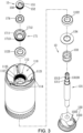
- FIG. 2 is a cross-sectional view along line A-A' of FIG. 1 .
- FIG. 3 is a schematic exploded view of a part of the coffee bean grinder of the present disclosure.
- a coffee bean grinder 1 is provided, which comprises a housing assembly 11, a shaft component 13, and a securing member 15.
- the housing assembly 11 comprises a housing 111, a bearing component 112, and an outer grinding member 113, where the bearing component 112 and the outer grinding member 113 are disposed in the housing 111, and the outer grinding member 113 is disposed below the bearing component 112.
- the shaft component 13 is assembled in the housing 111 and comprises a shaft member 131, an inner grinding member 132, and an elastic member 133.
- One end of the shaft member 131 comprises a connecting shaft 1311 and a shaft cap 1312.
- the shaft cap 1312 is disposed at the connecting shaft 1311.
- An outer diameter of a bottom end of the shaft cap 1312 is greater than an outer diameter of the connecting shaft 1311.
- the inner grinding member 132 is disposed at the other end of the shaft member 131.
- One end of the shaft member 131 passes through the elastic member 133 and the bearing component 112 in order.
- the elastic member 133 is disposed between the inner grinding member 132 and the bearing component 112, and two ends of the elastic member 133 support the inner grinding member 132 and the bearing component 112, respectively.
- the inner grinding member 132 and the outer grinding member 113 are correspondingly disposed, and a grinding gap G exists between the inner grinding member 132 and the outer grinding member 113.
- the shaft member 131 drives the inner grinding member 132 to rotate relative to the outer grinding member 113.
- the coffee beans are ground by the cooperating operation of the inner grinding member 132 and the outer grinding member 113.
- the coffee powder is discharged through the grinding gap G.
- An accommodating space 110 exists between the housing 111 and the bearing component 112, and the accommodating space 110 is in communication with the grinding gap G.
- a inclined grinding surface 1321 of the inner grinding member 132 is opposite to an annular grinding surface 1131 of the outer grinding member 113 with a grinding gap G therebetween.
- the inclined grinding surface 1321 of the inner grinding member 132 comprises a first grinding surface 1322 and a second grinding surface 1323.
- the first grinding surface 1322 is disposed above the second grinding surface 1323.
- a grinding pattern of the second grinding surface 1323 has a greater pattern density than a grinding pattern of the first grinding surface 1322.
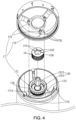
- FIG. 4 is another schematic exploded view of a part of the coffee bean grinder of the present disclosure.
- the securing member 15 comprises a body 150, a securing hole 151, and a securing groove 152.
- An opening shape of the securing hole 151 and an opening shape of the securing groove 152 are identical to the shape of a shoulder 13120 provided at the bottom end of the shaft cap 1312.
- the securing groove 152 is disposed at the body 150.
- the securing hole 151 penetrates the body 150 corresponding to a position of the securing groove 152.
- An opening angular position of the securing groove 152 on a surface of the body 150 is different from an opening angular position of the securing hole 151 on a surface of the body 150.
- the shape of the opening of the securing hole 151, the shape of the opening of the securing groove 152, and the shape of a periphery of the shoulder 13120 of the shaft cap 1312 are polygonal, for example, hexagon, pentagon, quadrilateral, or triangle, but it should not be limited thereto, where the above-mentioned shapes can be selected and adjusted according to requirements.
- the shape of components in this embodiment is hexagonal as an example.
- the opening of the securing groove 152 and the opening of the securing hole 151 are hexagonal.
- the securing groove 152 and the securing hole 151 are overlapped and disposed on the securing member 15.
- the opening angular position of the securing groove 152 is different from the opening angular position of the securing hole 151, that is, the opening of the securing groove 152 is co-center with the opening of the securing hole 151, but one of the two hexagonal openings is deflected form another.
- the securing groove 152 and the securing hole 151 overlap at the center part.
- corners of the opening of the securing groove 152 and corners of the securing hole would be misaligned and do not overlap, i.e., the corners of the opening of the securing groove 152 correspond to an outer side of an edge of the opening of the securing hole 151, and the corners of the opening of the securing hole 151 correspond to an outside of a side edge of the opening of the securing groove 152.
- an area of the securing groove 152 that is not penetrated by the securing hole 151 i.e., the corners of the opening of the securing groove 152 would still comprise the bottom of the securing groove 152 as the shoulder 13120 for supporting the shaft cap 1312.
- FIG. 5 depicts a first step of a securing action of a securing member secured to a shaft member of the present disclosure.
- the securing hole 151 of the securing member 15 corresponds to the shape of the periphery of the shoulder 13120 of the shaft cap 1312, so that the connecting shaft 1311 of the shaft member 131 and the shaft cap 1312 could pass through the securing hole 151 of the securing member 15.
- the dotted lines in FIG. 5 show a schematic range of the opening area of the securing hole 151, and also indicate an area where the shaft cap 1312 and the connecting shaft 1311 passing upward through the securing hole 151 of the securing member 15.
- FIG. 6 depicts a second step of the securing action of the securing member secured to the shaft member of the present disclosure.
- the securing member 15 would press downward against the bearing component 112 of the housing assembly 11 (see FIG. 2 ), so that the bearing component 112 of the housing assembly 11 could press downward against the elastic member 133, and the height of the shoulder 13120 of the shaft cap 1312 is disposed above the opening of the securing hole 151 of the securing member 15, that is, the connecting shaft 1311 is disposed in the securing hole 151 of the securing member 15.
- FIG. 7 depicts a third step of the securing action of the securing member secured to the shaft member of the present disclosure.
- a diameter of the securing hole 151 of the securing member 15 is greater than an outer diameter of the connecting shaft 1311, so the securing member 15 can be rotated from an angle at which the opening of the securing hole 151 corresponding to the shoulder 13120 of the shaft cap 1312 to an angle at which the opening of the securing groove 152 corresponding to the shoulder 13120 of the shaft cap 1312. That is, the corners of the shoulder 13120 of the shaft cap 1312 could correspond to positions above the corners of the securing grooves 152 having the bottom.
- the dotted lines shown in FIG. 7 draw a schematic range of the opening area of the securing groove 152.
- FIG. 8 depicts a fourth step of the securing action of the securing member secured to the shaft member of the present disclosure.
- an external force of the securing member 15 pushing down the bearing component 112 of the housing assembly 11 can be released, so that the elastic member 133 would be no longer under pressure.
- the elastic member 133 restores the elastic force to upwardly support the bearing component 112 of the housing assembly 11, so that the bearing component 112 could upwardly support the securing member 15, the shoulder 13120 of the shaft cap 1312 could be embedded in the securing groove 152, and the bottom of the securing groove 152 could support the corners of the shoulder 13120.
- the securing member 15 could be secured between the shaft cap 1312 and the bearing component 112.
- the bearing component 112 comprises a bearing part 1121, a first ball bearing 1122, and a second ball bearing 1123.
- a bottom of the bearing part 1121 comprises a lower bearing groove 1124, and a top of the bearing part 1121 comprises an upper bearing groove 1125.
- the bearing part 1121 comprises a shaft hole 1126 interconnected with the lower bearing groove 1124 and the upper bearing groove 1125.
- the first ball bearing 1122 is disposed in the lower bearing groove 1124, and the second ball bearing 1123 is disposed in the upper bearing groove 1125.
- the shaft member 131 penetrates the first ball bearing 1122, the shaft bearing part 1121, and the second ball bearing 1123. The first ball bearing 1122 and the second ball bearing 1123 are secured to the shaft member 131.
- the shaft component 13 further comprises a collar 134 that is sleeved on the shaft member 131.
- the collar 134 is disposed between the elastic member 133 and the bottom of the bearing component 112. The collar 134 could improve the supporting stability for one end of the elastic member 133.
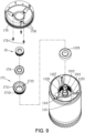
- FIG. 9 is yet another schematic exploded view of a part of the coffee bean grinder of the present disclosure.
- an adjusting component 17 is further provided, which comprises an adjusting member 171, a plurality of driving rods 172, and a rotating ring 173.
- An outer side of a bottom of the adjusting member 171 comprises an external thread 1713
- an inner side of the upper bearing groove 1125 comprises an internal thread 1127.
- the external thread 1713 at the bottom of the adjusting member 171 can be screwed with the internal thread 1127 inside the upper bearing groove 1125.
- the adjusting member 171 supports the securing member 15 from below, a periphery of a top of the adjusting member 171 comprises a toothed ring 1711, the rotating ring 173 is rotatably disposed on the housing assembly 11, the plurality of driving rods 172 are disposed at the rotating ring 173, and the driving rods 172 are respectively engaged with the toothed ring 1711.
- the rotating ring 173 drives the driving rods 172 to rotate, and the driving rods 172 are linked with the toothed ring 1711 to drive the adjusting member 171 to rotate to rise or descend relative to the upper bearing groove 1125.
- the adjusting member 171 When the adjusting member 171 rotates and descends, it would support the securing member 15 to move downward, the securing member 15 would no longer act on the shaft member 131, and meanwhile, the inner grinding member 132 of the shaft member 131 would no longer compress the elastic member 133 in a direction toward the bearing component 112.
- the elastic restoring force of the elastic member 133 can push the inner grinding member 132 downwardly and drives the shaft member 131 to move downward, and the inclined grinding surface 1321 of the inner grinding member 132 would be separated from the annular grinding surface 1131 of the outer grinding member 113 of the housing assembly 11 to increase the grinding gap G. In this way, the ground coffee bean powder would be coarse particles.
- the adjusting component 17 further comprises a third ball bearing 174
- the adjusting member 171 comprises a recess 1712
- the third ball bearing 174 is disposed in the recess 1712
- the securing member 15 is disposed on the third ball bearing 174.
- the third ball bearing 174 also penetrates the shaft member 131. So, the third ball bearing 174 can be used to reduce the rotational friction force between the securing member 15 and the adjusting member 171.
- an outer side of a top of the housing assembly 11 comprises a plurality of bumps 114
- an inner side of the rotating ring 173 comprises a plurality of notches 1731.
- the bumps 114 correspond to the notches 1731, and are disposed on rotation paths of the notches 1731 of the rotating ring 173. During the rotation of the rotating ring 173, the vibration and sound of the bumps 114 moving into or out of the notches 1731 can be clearly felt and heard.
- an outer surface of the rotating ring 173 is labeled with numbers, so during rotation, the grinding gap G can be adjusted by adjusting the rotating distance by turning the numbers and scales labeled on the rotating ring 173.
- the outer side of the top of the housing assembly 11 is labeled with a zero mark 115 between the two bumps 114.
- the inner grinding member 132 of the shaft member 131 can be raised to the highest position.
- the grinding gap G is in a closed state, rotate the number or the zero point of the scale on the outer surface of the rotating ring 173 to the position corresponding to the zero mark 115 for assembling. In this way, users could see that the grinding gap G of the coffee bean grinder 1 is at the zero point of the closed state.
- it can be adjusted to a desired gap distance by turning the rotating ring 173 to a certain point of the scale in correspondence with the desired gap distance by taking the zero mark 115 as reference point.
- FIG. 10 is yet another schematic exploded view of a part of the coffee bean grinder of the present disclosure.
- a handling component 19 is further provided.
- the handling component 19 comprises a pivoting member 191, a handling rod 192, and a handling knob 193.
- the pivoting member 191 is disposed at one end of the handling rod 192
- the handling knob 193 is disposed at the other end of the handling rod 192
- the pivoting member 191 is assembled on the shaft cap 1312.
- the shaft cap 1312 comprises a slot 1313
- the pivoting member 191 is embedded in the shaft cap 1312
- the shaft cap 1312 and the pivoting member 191 are magnetic members, which are mutually magnetically attracted for assembling and securing.
- a covering component 21 is further provided, which comprises a support 211 and a cover 212.
- the support 211 is assembled on the shaft cap 1312
- the cover 212 is assembled on the support 211
- the cover 212 covers and is disposed above of the accommodating space 110.
- an accommodating member 23 is further provided, comprises an accommodating groove 231 corresponding to an outlet of the grinding gap G, and the accommodating member 23 collects the ground coffee powder.
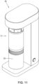
- FIG. 11 is a perspective view showing a connecting condition of the coffee bean grinder to a motor mechanism of the present disclosure.
- a motor mechanism 25 is further provided, which is connected to the shaft member 131 and can drive the shaft member 131 to rotate.
- the shaft member 131 drives the inner grinding member 132 to rotate relative to the outer grinding member 113 for motored coffee bean grinding, where the motor mechanism 25 can be a motor or any driving element.
- the motor mechanism 25 can be at least the base described in another Taiwanese patent (application number: 111203945 ) filed by the applicant of this disclosure, where the base is connected to a shaft member 131 through a drive shaft of the first assembling part, as long as the length and structural configuration of the drive shaft is in coordination with the overall shape and size of the coffee bean grinder of the present disclosure.
- embodiments of the present disclosure provide a coffee bean grinder, comprising a housing assembly, a shaft component, and a securing member, where the shaft component is assembled in the housing assembly.
- a coffee bean grinding complex is formed by the inner grinding member of the shaft component and the outer grinding member of the housing assembly, the shaft component and the housing assembly can be easily assembled and secured through the structural configuration of the securing member, and also through which, the shaft component and the housing assembly can also be disassembled for cleaning and maintenance after grinding operation.
Landscapes
- Engineering & Computer Science (AREA)
- Mechanical Engineering (AREA)
- Food Science & Technology (AREA)
- Apparatus For Making Beverages (AREA)
- Food-Manufacturing Devices (AREA)
- Tea And Coffee (AREA)
Claims (13)
- Kaffeemühle, Folgendes umfassend:eine Gehäuseanordnung (11), die ein Gehäuse (111), eine Lagerkomponente (112) und ein äußeres Mahlelement (113) umfasst, wobei die Lagerkomponente in dem Gehäuse angeordnet ist, das äußere Mahlelement in das Gehäuse eingebaut ist, das äußere Mahlelement unter der Lagerkomponente angeordnet ist,eine Wellenkomponente (13), die in das Gehäuse eingebaut ist, wobei die Wellenkomponente ein Wellenelement (131), ein inneres Mahlelement (132) und ein elastisches Element (133) umfasst, wobei ein Ende des Wellenelements eine Verbindungswelle (1311) und eine Wellenkappe (1312) umfasst, die Wellenkappe an der Verbindungswelle (1311) angeordnet ist, ein Außendurchmesser eines unteren Endes der Wellenkappe (1312) größer als ein Außendurchmesser der Verbindungswelle ist, das innere Mahlelement (132) an dem anderen Ende des Wellenelements angeordnet ist, ein Ende des Wellenelements nacheinander durch das elastische Elemente (133) und die Lagerkomponente (112) verläuft, das elastische Element zwischen dem inneren Mahlelement und der Lagerkomponente angeordnet ist, zwei Enden des elastischen Elements das innere Mahlelement beziehungsweise die Lagerkomponente tragen, das innere Mahlelement und das äußere Mahlelement entsprechend angeordnet sind, zwischen dem inneren Malelement und dem äußeren Mahlelement ein Mahlspalt (G) besteht, das Wellenelement das innere Mahlelement zur Drehung relativ zu dem äußeren Mahlelement antreibt, um das Mahlen durch das Zusammenwirken des inneren Mahlelements und des äußeren Mahlelements durchzuführen, undein Sicherungselement (15), das einen Hauptteil (150), ein Sicherungsloch (151) und eine Sicherungsrille (152) umfasst, wobei eine Form einer Öffnung des Sicherungslochs und eine Form einer Öffnung der Sicherungsrille (152) mit einer Form eines Außenumfangs des unteren Endes der Wellenkappe identisch sind, die Sicherungsrille (152) an dem Hauptteil angeordnet ist, das Sicherungsloch den Hauptteil in Übereinstimmung mit einer Position der Sicherungsrille durchdringt, sich eine Öffnungswinkelposition der Sicherungsrille an einer Oberfläche des Hauptteils von einer Öffnungswinkelposition des Sicherungslochs an der Oberfläche des Hauptteils unterscheidet,wobei die Wellenkappe (1312) beim Zusammenbau entsprechend durch das Sicherungsloch des Sicherungselements verläuft, wo das Sicherungselement gegen die Lagerkomponente und das elastische Element (133) nach unten drückt, das elastische Element im zusammengebauten Zustand die Lagerkomponente und das Sicherungselement aufwärts trägt, das untere Ende der Wellenkappe (1312) in die Sicherungsrille des Sicherungselements eingebettet ist und das Sicherungselement zwischen der Wellenkappe und der Lagerkomponente gesichert ist.
- Kaffeemühle nach Anspruch 1, wobei die Lagerkomponente einen Lagerteil (1121), ein erstes Kugellager (1122) und ein zweites Kugellager (1123) umfasst, eine Unterseite des Lagerteils eine untere Lagerrille (1124) umfasst, eine Oberseite des Lagerteils eine obere Lagerrille (1125) umfasst, der Lagerteil ein Wellenloch (1126) umfasst, das die untere Lagerrille und die obere Lagerrille verbindet, das erste Kugellager in der unteren Lagerrille angeordnet ist, das zweite Kugellager in der oberen Lagerrille angeordnet ist, das Wellenelement durch das erste Kugellager, den Lagerteil und das zweite Kugellager verläuft.
- Kaffeemühle nach Anspruch 1, wobei die Wellenkomponente ferner einen Kranz (134) umfasst, der auf das Wellenelement aufgesetzt ist, wobei der Kranz zwischen dem elastischen Element und einer Unterseite der Lagerkomponente angeordnet ist.
- Kaffeemühle nach Anspruch 1, wobei das untere Ende der Wellenkappe mit einem Absatz (13120) versehen ist, die Form der Öffnung des Sicherungslochs, die Form der Öffnung der Sicherungsrille und eine Form eines Außenumfangs des Absatzes der Wellenkappe (1312) vieleckig sind.
- Kaffeemühle nach Anspruch 2, eine Justierungskomponente (17) umfassend, die ein Justierungselement (171), mehrere Antriebsstangen (172) und einen Drehring (173) umfasst, wobei eine Unterseite des Justierungselements in die obere Lagerrille geschraubt ist, das Justierungselement das Sicherungselement trägt, ein Außenumfang einer Oberseite des Justierungselements einen Zahnring (1711) umfasst, der Drehring drehbar an der Gehäuseanordnung angebracht ist, die mehreren Antriebsstangen an dem Drehring angeordnet sind, die mehreren Antriebsstangen entsprechend mit dem Zahnring in Eingriff stehen, wobei der Drehring die mehreren Antriebsstangen zum Drehen antreibt, die mehreren Antriebsstangen mit dem Zahnring verknüpft sind, um das Justierungselement anzutreiben, sich relativ zu der oberen Lagerrille auf- oder abwärts zu drehen.
- Kaffeemühle nach Anspruch 5, ein drittes Kugellager (174) umfassend, wobei das Justierungselement eine Vertiefung (1712) umfasst, in der das dritte Kugellager angeordnet ist, das Sicherungselement an dem dritten Kugellager angeordnet ist.
- Kaffeemühle nach Anspruch 5, wobei eine Außenseite einer Oberseite der Gehäuseanordnung mehrere Buckel (114) umfasst, eine Innenseite des Drehrings mehrere Kerben (1731) umfasst, die mehreren Buckel den mehreren Kerben entsprechen, die mehreren Buckel auf Drehwegen der mehreren Kerben angeordnet sind.
- Kaffeemühle nach Anspruch 1, eine Bedienungskomponente (19) umfassend, die ein drehendes Element (191), eine Bedienstange (192) und einen Bedienungsknauf (193) umfasst, wobei das drehende Element an einem Ende der Bedienungsstange angeordnet ist, der Bedienungsknauf an dem anderen Ende der Bedienungsstange angeordnet ist, das drehende Element an die Wellenkappe angebaut ist.
- Kaffeemühle nach Anspruch 8, wobei die Wellenkappe einen Schlitz (1313) umfasst, das drehende Element in die Wellenkappe eingebettet ist, die Wellenkappe und das drehende Element magnetische Elemente sind, die Wellenkappe und das drehende Element einander magnetisch anziehen.
- Kaffeemühle nach Anspruch 1, wobei zwischen dem Gehäuse (111) und der Lagerkomponente (112) ein Unterbringungsraum (110) vorhanden ist, wobei der Unterbringungsraum in Verbindung mit dem Mahlspalt steht.
- Kaffeemühle nach Anspruch 10, eine Abdeckkomponente (21) umfassend, die einen Träger (211) und eine Abdeckung (212) umfasst, wobei der Träger an die Wellenkappe angebaut ist, die Abdeckung an den Träger angebaut ist, die Abdeckung über dem Unterbringungsraum angeordnet ist und selbigen abdeckt.
- Kaffeemühle nach Anspruch 1, wobei eine geneigte Mahlfläche (1321) des inneren Mahlelements den Mahlspalt (G) relativ zu einer ringförmigen Mahlfläche (1131) des äußeren Malelements umfasst, wobei die geneigte Mahlfläche des inneren Mahlelements eine erste Mahlfläche (1322) und eine zweite Mahlfläche (1323) umfasst, die erste Mahlfläche (1322) über der zweiten Mahlfläche angeordnet ist, eine Mahlstruktur auf der zweiten Mahlfläche (1323) eine größere Strukturdichte als eine Mahlstruktur auf der ersten Mahlfläche aufweist.
- Kaffeemühle nach Anspruch 1, einen Motormechanismus (25) umfassend, der mit dem Wellenelement (131) verbunden ist.
Applications Claiming Priority (1)
| Application Number | Priority Date | Filing Date | Title |
|---|---|---|---|
| TW111126356A TWI805443B (zh) | 2022-07-13 | 2022-07-13 | 咖啡豆研磨裝置 |
Publications (3)
| Publication Number | Publication Date |
|---|---|
| EP4306014A1 EP4306014A1 (de) | 2024-01-17 |
| EP4306014B1 true EP4306014B1 (de) | 2024-09-04 |
| EP4306014C0 EP4306014C0 (de) | 2024-09-04 |
Family
ID=83193580
Family Applications (1)
| Application Number | Title | Priority Date | Filing Date |
|---|---|---|---|
| EP22193940.8A Active EP4306014B1 (de) | 2022-07-13 | 2022-09-05 | Kaffeebohnenmühle |
Country Status (7)
| Country | Link |
|---|---|
| US (1) | US11857113B1 (de) |
| EP (1) | EP4306014B1 (de) |
| JP (1) | JP7837053B2 (de) |
| CN (1) | CN117426683A (de) |
| AU (1) | AU2022224835B2 (de) |
| SA (1) | SA122440841B1 (de) |
| TW (1) | TWI805443B (de) |
Families Citing this family (5)
| Publication number | Priority date | Publication date | Assignee | Title |
|---|---|---|---|---|
| JP1780175S (ja) * | 2023-07-10 | 2024-09-18 | 非電動グラインダーの本体部品 | |
| USD1069228S1 (en) * | 2023-07-28 | 2025-04-01 | Spark Perceptions Technology, Inc. | Personal herb grinding device |
| USD1097682S1 (en) * | 2023-08-24 | 2025-10-14 | Hangzhou Hengmu Supply Chain Management Services Co., Ltd. | Coffee grinder |
| USD1096281S1 (en) * | 2023-08-24 | 2025-10-07 | Hangzhou Hengmu Supply Chain Management Services Co., Ltd. | Coffee grinder |
| US20250302235A1 (en) * | 2024-03-27 | 2025-10-02 | YearWeekDaily Limited | High-precision externally-adjustable coffee grinder |
Family Cites Families (22)
| Publication number | Priority date | Publication date | Assignee | Title |
|---|---|---|---|---|
| US2782998A (en) * | 1953-08-14 | 1957-02-26 | Jr Earle G Hastings | Barbecue pepper mill |
| US4771955A (en) * | 1982-04-29 | 1988-09-20 | Paulson John K | Pepper mill closure |
| JPH0420376Y2 (de) * | 1987-11-17 | 1992-05-11 | ||
| US5626299A (en) * | 1995-06-01 | 1997-05-06 | Haynes; Brian T. | Condiment mill with conveying space |
| US6851635B2 (en) * | 2001-04-09 | 2005-02-08 | William Bounds, Ltd. | Condiment mill |
| TW200833282A (en) * | 2007-02-05 | 2008-08-16 | Chung-Jen Pai | A grinder |
| DE602007003735D1 (de) | 2007-10-01 | 2010-01-21 | Wu Ching Yueh Wang | Mühle zum Mahlen essbarer Partikel |
| TW201029613A (en) * | 2009-02-09 | 2010-08-16 | Yienn Lih Entpr Co Ltd | Pepper grinder |
| GB2468334A (en) * | 2009-03-04 | 2010-09-08 | Yienn Lih Entpr Co Ltd | Pepper mill |
| US20100276527A1 (en) * | 2009-04-29 | 2010-11-04 | Progressive International Corporation | Spice mills and shakers |
| US8444074B2 (en) * | 2010-01-04 | 2013-05-21 | Yienn Lih Enterprise Co., Ltd. | Pepper mill |
| TWM517584U (zh) * | 2015-09-09 | 2016-02-21 | 瀛麗企業股份有限公司 | 胡椒研磨器 |
| US10517435B2 (en) * | 2015-12-21 | 2019-12-31 | Japan Porlex & Co., Ltd. | Mill device |
| CN208463787U (zh) * | 2018-02-01 | 2019-02-05 | 佛山市顺德区凌动电器制造有限公司 | 一种易拆式手摇磨豆机 |
| EP3753460A4 (de) * | 2019-04-26 | 2021-07-28 | Japan Porlex & Co., Ltd. | Mörtelkörper und fräsvorrichtung |
| US11457772B2 (en) * | 2019-09-04 | 2022-10-04 | Helen Of Troy Limited | Manual coffee grinder |
| DE202019107282U1 (de) * | 2019-12-30 | 2020-01-23 | Huachun Zhan | Faltstruktur einer manuellen Bohnenmühle |
| CN212037251U (zh) | 2020-03-06 | 2020-12-01 | 厦门福庆工贸有限公司 | 一种咖啡豆研磨器 |
| US11717113B2 (en) * | 2020-06-23 | 2023-08-08 | Survival Light Products, Inc. | Coffee grinder systems and methods |
| CN213345378U (zh) | 2020-07-27 | 2021-06-04 | 李剑锋 | 一种咖啡豆研磨机 |
| CN214284612U (zh) | 2020-08-09 | 2021-09-28 | 厦门思奇家居用品有限公司 | 一种防堵塞咖啡豆研磨器 |
| TWM637070U (zh) * | 2022-07-13 | 2023-02-01 | 創康機械科技股份有限公司 | 咖啡豆研磨裝置 |
-
2022
- 2022-07-13 TW TW111126356A patent/TWI805443B/zh active
- 2022-08-02 CN CN202210923438.1A patent/CN117426683A/zh active Pending
- 2022-08-29 US US17/898,064 patent/US11857113B1/en active Active
- 2022-09-02 AU AU2022224835A patent/AU2022224835B2/en active Active
- 2022-09-05 EP EP22193940.8A patent/EP4306014B1/de active Active
- 2022-09-14 JP JP2022146047A patent/JP7837053B2/ja active Active
- 2022-12-12 SA SA122440841A patent/SA122440841B1/ar unknown
Also Published As
| Publication number | Publication date |
|---|---|
| TW202402225A (zh) | 2024-01-16 |
| US20240016339A1 (en) | 2024-01-18 |
| TWI805443B (zh) | 2023-06-11 |
| CN117426683A (zh) | 2024-01-23 |
| SA122440841B1 (ar) | 2024-10-15 |
| US11857113B1 (en) | 2024-01-02 |
| AU2022224835B2 (en) | 2025-02-27 |
| EP4306014A1 (de) | 2024-01-17 |
| JP7837053B2 (ja) | 2026-03-30 |
| CA3171574A1 (en) | 2024-01-13 |
| JP2024012019A (ja) | 2024-01-25 |
| EP4306014C0 (de) | 2024-09-04 |
| AU2022224835A1 (en) | 2024-02-01 |
Similar Documents
| Publication | Publication Date | Title |
|---|---|---|
| EP4306014A1 (de) | Kaffeebohnenmühle | |
| US7207511B2 (en) | Condiment grinder | |
| CN110693352B (zh) | 一种研磨机构、研磨机和研磨方法 | |
| CN217772112U (zh) | 手动研磨器 | |
| CN220327336U (zh) | 一种双轴联动上下独立调节咖啡豆研磨机 | |
| CN215016411U (zh) | 一种便于调节颗粒粗细的咖啡磨豆机 | |
| CN218552139U (zh) | 咖啡豆研磨装置 | |
| CA3171574C (en) | Coffee bean grinder | |
| CN218219990U (zh) | 磨料机构及磨豆机 | |
| GB2605990A (en) | A coffee grinder | |
| CN218165011U (zh) | 一种食品研磨装置 | |
| EP4265164A1 (de) | Kaffeemühle | |
| CN100581430C (zh) | 食用粒料研磨器 | |
| JP3239818U (ja) | コーヒーグラインダー | |
| CN217549988U (zh) | 一种可调节研磨粗细的研磨装置 | |
| CN222149834U (zh) | 一种可调节粗细研磨度的磨豆机 | |
| CN223913998U (zh) | 一种可旋转调节的研磨器 | |
| CN221931827U (zh) | 一种外部调节粗细度的磨豆机结构 | |
| CN223695677U (zh) | 研磨装置及研磨机 | |
| EP4613155B1 (de) | Handmühle | |
| CN222129935U (zh) | 一种咖啡豆研磨结构、研磨机及咖啡机 | |
| CN223944284U (zh) | 咖啡豆磨豆机 | |
| JP3252872U (ja) | 研磨度調節可能なコーヒーグラインダー | |
| GB2355675A (en) | Food grinder | |
| CN219846212U (zh) | 外芯可调的外调式咖啡研磨装置 |
Legal Events
| Date | Code | Title | Description |
|---|---|---|---|
| PUAI | Public reference made under article 153(3) epc to a published international application that has entered the european phase |
Free format text: ORIGINAL CODE: 0009012 |
|
| STAA | Information on the status of an ep patent application or granted ep patent |
Free format text: STATUS: REQUEST FOR EXAMINATION WAS MADE |
|
| 17P | Request for examination filed |
Effective date: 20220905 |
|
| AK | Designated contracting states |
Kind code of ref document: A1 Designated state(s): AL AT BE BG CH CY CZ DE DK EE ES FI FR GB GR HR HU IE IS IT LI LT LU LV MC MK MT NL NO PL PT RO RS SE SI SK SM TR |
|
| GRAP | Despatch of communication of intention to grant a patent |
Free format text: ORIGINAL CODE: EPIDOSNIGR1 |
|
| STAA | Information on the status of an ep patent application or granted ep patent |
Free format text: STATUS: GRANT OF PATENT IS INTENDED |
|
| INTG | Intention to grant announced |
Effective date: 20240408 |
|
| GRAS | Grant fee paid |
Free format text: ORIGINAL CODE: EPIDOSNIGR3 |
|
| GRAA | (expected) grant |
Free format text: ORIGINAL CODE: 0009210 |
|
| STAA | Information on the status of an ep patent application or granted ep patent |
Free format text: STATUS: THE PATENT HAS BEEN GRANTED |
|
| AK | Designated contracting states |
Kind code of ref document: B1 Designated state(s): AL AT BE BG CH CY CZ DE DK EE ES FI FR GB GR HR HU IE IS IT LI LT LU LV MC MK MT NL NO PL PT RO RS SE SI SK SM TR |
|
| REG | Reference to a national code |
Ref country code: GB Ref legal event code: FG4D |
|
| REG | Reference to a national code |
Ref country code: CH Ref legal event code: EP |
|
| REG | Reference to a national code |
Ref country code: IE Ref legal event code: FG4D |
|
| REG | Reference to a national code |
Ref country code: DE Ref legal event code: R096 Ref document number: 602022005844 Country of ref document: DE |
|
| U01 | Request for unitary effect filed |
Effective date: 20240911 |
|
| U07 | Unitary effect registered |
Designated state(s): AT BE BG DE DK EE FI FR IT LT LU LV MT NL PT RO SE SI Effective date: 20240917 |
|
| U20 | Renewal fee for the european patent with unitary effect paid |
Year of fee payment: 3 Effective date: 20240912 |
|
| PG25 | Lapsed in a contracting state [announced via postgrant information from national office to epo] |
Ref country code: NO Free format text: LAPSE BECAUSE OF FAILURE TO SUBMIT A TRANSLATION OF THE DESCRIPTION OR TO PAY THE FEE WITHIN THE PRESCRIBED TIME-LIMIT Effective date: 20241204 |
|
| PG25 | Lapsed in a contracting state [announced via postgrant information from national office to epo] |
Ref country code: GR Free format text: LAPSE BECAUSE OF FAILURE TO SUBMIT A TRANSLATION OF THE DESCRIPTION OR TO PAY THE FEE WITHIN THE PRESCRIBED TIME-LIMIT Effective date: 20241205 |
|
| PG25 | Lapsed in a contracting state [announced via postgrant information from national office to epo] |
Ref country code: HR Free format text: LAPSE BECAUSE OF FAILURE TO SUBMIT A TRANSLATION OF THE DESCRIPTION OR TO PAY THE FEE WITHIN THE PRESCRIBED TIME-LIMIT Effective date: 20240904 |
|
| PG25 | Lapsed in a contracting state [announced via postgrant information from national office to epo] |
Ref country code: RS Free format text: LAPSE BECAUSE OF FAILURE TO SUBMIT A TRANSLATION OF THE DESCRIPTION OR TO PAY THE FEE WITHIN THE PRESCRIBED TIME-LIMIT Effective date: 20241204 Ref country code: ES Free format text: LAPSE BECAUSE OF FAILURE TO SUBMIT A TRANSLATION OF THE DESCRIPTION OR TO PAY THE FEE WITHIN THE PRESCRIBED TIME-LIMIT Effective date: 20240904 |
|
| PG25 | Lapsed in a contracting state [announced via postgrant information from national office to epo] |
Ref country code: RS Free format text: LAPSE BECAUSE OF FAILURE TO SUBMIT A TRANSLATION OF THE DESCRIPTION OR TO PAY THE FEE WITHIN THE PRESCRIBED TIME-LIMIT Effective date: 20241204 Ref country code: NO Free format text: LAPSE BECAUSE OF FAILURE TO SUBMIT A TRANSLATION OF THE DESCRIPTION OR TO PAY THE FEE WITHIN THE PRESCRIBED TIME-LIMIT Effective date: 20241204 Ref country code: HR Free format text: LAPSE BECAUSE OF FAILURE TO SUBMIT A TRANSLATION OF THE DESCRIPTION OR TO PAY THE FEE WITHIN THE PRESCRIBED TIME-LIMIT Effective date: 20240904 Ref country code: GR Free format text: LAPSE BECAUSE OF FAILURE TO SUBMIT A TRANSLATION OF THE DESCRIPTION OR TO PAY THE FEE WITHIN THE PRESCRIBED TIME-LIMIT Effective date: 20241205 Ref country code: ES Free format text: LAPSE BECAUSE OF FAILURE TO SUBMIT A TRANSLATION OF THE DESCRIPTION OR TO PAY THE FEE WITHIN THE PRESCRIBED TIME-LIMIT Effective date: 20240904 |
|
| PG25 | Lapsed in a contracting state [announced via postgrant information from national office to epo] |
Ref country code: IS Free format text: LAPSE BECAUSE OF FAILURE TO SUBMIT A TRANSLATION OF THE DESCRIPTION OR TO PAY THE FEE WITHIN THE PRESCRIBED TIME-LIMIT Effective date: 20250104 |
|
| PG25 | Lapsed in a contracting state [announced via postgrant information from national office to epo] |
Ref country code: SM Free format text: LAPSE BECAUSE OF FAILURE TO SUBMIT A TRANSLATION OF THE DESCRIPTION OR TO PAY THE FEE WITHIN THE PRESCRIBED TIME-LIMIT Effective date: 20240904 |
|
| PG25 | Lapsed in a contracting state [announced via postgrant information from national office to epo] |
Ref country code: PL Free format text: LAPSE BECAUSE OF FAILURE TO SUBMIT A TRANSLATION OF THE DESCRIPTION OR TO PAY THE FEE WITHIN THE PRESCRIBED TIME-LIMIT Effective date: 20240904 Ref country code: CZ Free format text: LAPSE BECAUSE OF FAILURE TO SUBMIT A TRANSLATION OF THE DESCRIPTION OR TO PAY THE FEE WITHIN THE PRESCRIBED TIME-LIMIT Effective date: 20240904 |
|
| PG25 | Lapsed in a contracting state [announced via postgrant information from national office to epo] |
Ref country code: SK Free format text: LAPSE BECAUSE OF FAILURE TO SUBMIT A TRANSLATION OF THE DESCRIPTION OR TO PAY THE FEE WITHIN THE PRESCRIBED TIME-LIMIT Effective date: 20240904 |
|
| PG25 | Lapsed in a contracting state [announced via postgrant information from national office to epo] |
Ref country code: MC Free format text: LAPSE BECAUSE OF FAILURE TO SUBMIT A TRANSLATION OF THE DESCRIPTION OR TO PAY THE FEE WITHIN THE PRESCRIBED TIME-LIMIT Effective date: 20240904 |
|
| PLBE | No opposition filed within time limit |
Free format text: ORIGINAL CODE: 0009261 |
|
| STAA | Information on the status of an ep patent application or granted ep patent |
Free format text: STATUS: NO OPPOSITION FILED WITHIN TIME LIMIT |
|
| PG25 | Lapsed in a contracting state [announced via postgrant information from national office to epo] |
Ref country code: IE Free format text: LAPSE BECAUSE OF NON-PAYMENT OF DUE FEES Effective date: 20240905 |
|
| 26N | No opposition filed |
Effective date: 20250605 |
|
| U20 | Renewal fee for the european patent with unitary effect paid |
Year of fee payment: 4 Effective date: 20250924 |
|
| PG25 | Lapsed in a contracting state [announced via postgrant information from national office to epo] |
Ref country code: CY Free format text: LAPSE BECAUSE OF FAILURE TO SUBMIT A TRANSLATION OF THE DESCRIPTION OR TO PAY THE FEE WITHIN THE PRESCRIBED TIME-LIMIT; INVALID AB INITIO Effective date: 20220905 |
|
| PG25 | Lapsed in a contracting state [announced via postgrant information from national office to epo] |
Ref country code: HU Free format text: LAPSE BECAUSE OF FAILURE TO SUBMIT A TRANSLATION OF THE DESCRIPTION OR TO PAY THE FEE WITHIN THE PRESCRIBED TIME-LIMIT; INVALID AB INITIO Effective date: 20220905 |
|
| REG | Reference to a national code |
Ref country code: CH Ref legal event code: H13 Free format text: ST27 STATUS EVENT CODE: U-0-0-H10-H13 (AS PROVIDED BY THE NATIONAL OFFICE) Effective date: 20260504 |