EP4303041A1 - Barre transversale à trois points - Google Patents
Barre transversale à trois points Download PDFInfo
- Publication number
- EP4303041A1 EP4303041A1 EP23180870.0A EP23180870A EP4303041A1 EP 4303041 A1 EP4303041 A1 EP 4303041A1 EP 23180870 A EP23180870 A EP 23180870A EP 4303041 A1 EP4303041 A1 EP 4303041A1
- Authority
- EP
- European Patent Office
- Prior art keywords
- wishbone
- shaped
- connection points
- point
- base body
- Prior art date
- Legal status (The legal status is an assumption and is not a legal conclusion. Google has not performed a legal analysis and makes no representation as to the accuracy of the status listed.)
- Pending
Links
- 239000002184 metal Substances 0.000 claims abstract description 12
- 238000000034 method Methods 0.000 description 8
- 230000006835 compression Effects 0.000 description 7
- 238000007906 compression Methods 0.000 description 7
- 239000000463 material Substances 0.000 description 5
- 238000004519 manufacturing process Methods 0.000 description 4
- 229910000831 Steel Inorganic materials 0.000 description 2
- 239000010959 steel Substances 0.000 description 2
- 230000006978 adaptation Effects 0.000 description 1
- 238000005452 bending Methods 0.000 description 1
- 239000002131 composite material Substances 0.000 description 1
- 230000008878 coupling Effects 0.000 description 1
- 238000010168 coupling process Methods 0.000 description 1
- 238000005859 coupling reaction Methods 0.000 description 1
- 230000001419 dependent effect Effects 0.000 description 1
- 230000000694 effects Effects 0.000 description 1
- 238000005516 engineering process Methods 0.000 description 1
- 238000009434 installation Methods 0.000 description 1
- 238000003825 pressing Methods 0.000 description 1
- 230000000750 progressive effect Effects 0.000 description 1
- 230000003716 rejuvenation Effects 0.000 description 1
Images


Classifications
-
- B—PERFORMING OPERATIONS; TRANSPORTING
- B60—VEHICLES IN GENERAL
- B60G—VEHICLE SUSPENSION ARRANGEMENTS
- B60G7/00—Pivoted suspension arms; Accessories thereof
- B60G7/001—Suspension arms, e.g. constructional features
-
- B—PERFORMING OPERATIONS; TRANSPORTING
- B60—VEHICLES IN GENERAL
- B60G—VEHICLE SUSPENSION ARRANGEMENTS
- B60G2206/00—Indexing codes related to the manufacturing of suspensions: constructional features, the materials used, procedures or tools
- B60G2206/01—Constructional features of suspension elements, e.g. arms, dampers, springs
- B60G2206/017—Constructional features of suspension elements, e.g. arms, dampers, springs forming an eye for the bushing
-
- B—PERFORMING OPERATIONS; TRANSPORTING
- B60—VEHICLES IN GENERAL
- B60G—VEHICLE SUSPENSION ARRANGEMENTS
- B60G2206/00—Indexing codes related to the manufacturing of suspensions: constructional features, the materials used, procedures or tools
- B60G2206/01—Constructional features of suspension elements, e.g. arms, dampers, springs
- B60G2206/10—Constructional features of arms
- B60G2206/124—Constructional features of arms the arm having triangular or Y-shape, e.g. wishbone
-
- B—PERFORMING OPERATIONS; TRANSPORTING
- B60—VEHICLES IN GENERAL
- B60G—VEHICLE SUSPENSION ARRANGEMENTS
- B60G2206/00—Indexing codes related to the manufacturing of suspensions: constructional features, the materials used, procedures or tools
- B60G2206/01—Constructional features of suspension elements, e.g. arms, dampers, springs
- B60G2206/10—Constructional features of arms
- B60G2206/14—Constructional features of arms the arm forming a U-shaped recess for fitting a bush
- B60G2206/141—The recess being integrally or seamlessly formed
-
- B—PERFORMING OPERATIONS; TRANSPORTING
- B60—VEHICLES IN GENERAL
- B60G—VEHICLE SUSPENSION ARRANGEMENTS
- B60G2206/00—Indexing codes related to the manufacturing of suspensions: constructional features, the materials used, procedures or tools
- B60G2206/01—Constructional features of suspension elements, e.g. arms, dampers, springs
- B60G2206/10—Constructional features of arms
- B60G2206/16—Constructional features of arms the arm having a U profile and/or made of a plate
-
- B—PERFORMING OPERATIONS; TRANSPORTING
- B60—VEHICLES IN GENERAL
- B60G—VEHICLE SUSPENSION ARRANGEMENTS
- B60G2206/00—Indexing codes related to the manufacturing of suspensions: constructional features, the materials used, procedures or tools
- B60G2206/01—Constructional features of suspension elements, e.g. arms, dampers, springs
- B60G2206/70—Materials used in suspensions
- B60G2206/72—Steel
- B60G2206/722—Plates
-
- B—PERFORMING OPERATIONS; TRANSPORTING
- B60—VEHICLES IN GENERAL
- B60G—VEHICLE SUSPENSION ARRANGEMENTS
- B60G2206/00—Indexing codes related to the manufacturing of suspensions: constructional features, the materials used, procedures or tools
- B60G2206/01—Constructional features of suspension elements, e.g. arms, dampers, springs
- B60G2206/80—Manufacturing procedures
- B60G2206/81—Shaping
- B60G2206/8102—Shaping by stamping
Definitions
- the present invention relates to a three-point wishbone according to the features in the preamble of claim 1.
- Car bodies or self-supporting bodies are used in automotive technology.
- the wheels are connected to the bodies or axles or axle supports via handlebars or wishbones.
- Such links are known as shell components, in particular as sheet metal components made of a steel material.
- Y-shaped configurations for three-point wishbones are also known.
- a wishbone should be designed to be as torsionally rigid as possible in order to optimally support the kinematics during compression and rebound of the wheel.
- the object of the present invention is to provide a wishbone which is improved in terms of the manufacturing variant and the possibility of arrangement in the motor vehicle as well as the influence on the deflection and rebound processes of the wheel.
- the three-point wishbone for a motor vehicle is manufactured as a single-shell, in particular one-piece, material-formed sheet metal component. It has a Y-shaped base body.
- the three-point wishbone is made from a steel material as a formed component. Preferred wall thicknesses are between 1 mm and 5 mm, in particular between 3 mm and 4 mm.
- the three-point wishbone has three connection points.
- a connection point is formed on the wheel carrier side.
- Two connection points are formed on the axle support side or the motor vehicle side.
- each connection point i.e. all connection points, is formed from two opposite collar openings to accommodate a respective rubber-metal bearing.
- a collar opening is designed as a hole or opening, in particular a round opening, from which a collar extends.
- the respective receiving openings are preferably parallel to each other.
- the collars are oriented towards each other. Bearings are then inserted, in particular pressed, into the respective collar openings.
- These are particularly preferably rubber-metal bearings, in particular with an outer long sleeve.
- the cross member offers the possibility of being manufactured particularly cost-effectively as a single-shell, one-piece and uniform sheet metal forming component.
- Sheet metal forming component can be set to an already optimized adaptation to specified installation spaces. Because all connection points are also made in one piece and made from the same material, there are no coupling operations with other add-on parts, such as ball joints or similar. This saves production costs.
- a further advantage according to the invention is that at least one of the Y-shaped arms has a taper along its longitudinal course.
- a respective taper is preferably formed on both Y-shaped arms.
- the taper can be designed as a reduction in the geometric cross-sectional shape and/or a reduction in the cross-sectional area.
- the taper can alternatively or additionally be designed as a recess and therefore material removal.
- the recess is designed as a wave shape, particularly in the longitudinal course of the Y-shaped arm.
- the torsional rigidity of the arm in the area of the connection point is reduced.
- the torsional rigidity is particularly preferably reduced to a value of ⁇ 10 Nm/degree.
- the rigidity of the handlebar in particular a lateral rigidity of the handlebar, is particularly preferably increased to >50 kN/mm.
- the handlebar thus maintains the distance between the individual connection points in its longitudinal direction.
- the bearing points of the Y-shaped arms are arranged at an angle of 30 to 70 degrees, more precisely 35 to 60 degrees and particularly preferably 40 to 55 degrees, the Y-shaped arms can be formed in this way Twist your arms around their own axis without affecting the stiffness of the handlebars.
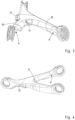
- FIG. 1 shows a three-point wishbone 1 according to the invention.
- the wishbone 1 has a Y-shaped base body 2 for this purpose. Two arms 3 protrude from this Y-shaped base body 2, which are also referred to as Y-shaped arms.
- a connection point is formed at each end.
- a wheel carrier-side connection point 4 is shown on the image plane on the left and two axle-carrier-side connection points 5 are shown on the image plane on the right.
- the connection points 5 themselves are formed by two opposite collar openings 6.
- the collar openings 6 themselves in turn have collars 7 that are directed inwards or point towards one another. This is also shown in Figure 2 , which is a bottom view of the wishbone according to Figure 1 represents.
- a respective bearing (not shown in detail) is pressed into the collar opening 6, especially a rubber-metal bearing.
- the forming tool can also be designed as a progressive composite tool or multi-stage pressing tool and the calibration can take place in one of the last or final stages.
- the base body and the arms are each C-shaped and U-shaped in their cross section.
- FIG. 2 Another essential aspect of the invention is presented in Figure 2 , but also especially in Figures 3, 4 and 5 shown.
- the Y-shaped arms 3 have a constriction 8 in the direction of the connection points 5 on the axle carrier side.
- the constriction 8 is here in the form of a recess 9 of the Y-shaped arm 3. This reduces the torsional rigidity in the area of the connection points 5 on the axle carrier side.
- the respective Y-shaped arm 3 can rotate in the loading point about its own longitudinal axis, so that the wishbone 1 does not offer any resulting increased bending resistance during a compression or rebound process.
- a depression 11 is also formed on the Y-fork of the base body 2. Due to the depression 11, the Y-shaped arms 3 can move relative to one another during the compression or rebound process.
- Outwardly oriented projecting flanges 12 are also formed at the wheel carrier end. These flanges 12 stiffen the connection point 4 at the end on the wheel carrier side, so that greater rigidity is formed here in the area of the base body 2. Overall, this results in a sufficiently rigid three-point wishbone 1, which is made in one piece and made of the same material. At the same time, the cross member 1 inherently offers elasticity or ductility, but at the same time the wishbone is given ductility or flexibility due to its inherent rigidity.
- Figure 6 shows a top view of the wishbone 1 according to the invention. It can be seen from this that the two connection points 5 on the axle carrier side are arranged or oriented at an angle ⁇ to one another. A respective extension of the central longitudinal section plane between the two collar openings 6 represents the extending orientation of the connection points 4, 5 for the bearings.
- Figure 7 shows a cross-sectional view along section line VII-VII Figure 6 .
- An opening direction 14 of the Y-shaped base body 2 or the Y-shaped arms 3 is oriented downwards in relation to the vertical direction.
- the wishbone 1 according to the invention is designed as a shell that is open on one side.
- An opening direction 14 is preferably arranged such that it runs transversely to a bearing axis, in particular transversely to all bearing axes 15, 16.
- all bearing axes 15, 16 of the connection points can lie in one plane. You can also see the C-shaped cross section of the arms.
- the depression 11 can also be seen at the fork point of the two arms.
- the depression 11 is embossed into the base body 2 oriented in the direction of the opening.
Landscapes
- Engineering & Computer Science (AREA)
- Mechanical Engineering (AREA)
- Vehicle Body Suspensions (AREA)
Applications Claiming Priority (1)
| Application Number | Priority Date | Filing Date | Title |
|---|---|---|---|
| DE102022117069.1A DE102022117069A1 (de) | 2022-07-08 | 2022-07-08 | Dreipunkt-Querlenker |
Publications (1)
| Publication Number | Publication Date |
|---|---|
| EP4303041A1 true EP4303041A1 (fr) | 2024-01-10 |
Family
ID=89069671
Family Applications (1)
| Application Number | Title | Priority Date | Filing Date |
|---|---|---|---|
| EP23180870.0A Pending EP4303041A1 (fr) | 2022-07-08 | 2023-06-22 | Barre transversale à trois points |
Country Status (3)
| Country | Link |
|---|---|
| EP (1) | EP4303041A1 (fr) |
| CN (1) | CN117360132A (fr) |
| DE (1) | DE102022117069A1 (fr) |
Citations (7)
| Publication number | Priority date | Publication date | Assignee | Title |
|---|---|---|---|---|
| US5310210A (en) * | 1991-12-10 | 1994-05-10 | Mascotech, Inc. | Upper control arm for vehicle suspension system |
| DE102007018569A1 (de) * | 2007-04-18 | 2008-10-30 | Thyssenkrupp Umformtechnik Gmbh | Fahrwerkslenker für ein Kraftfahrzeug |
| DE102009014194A1 (de) * | 2009-03-20 | 2010-09-23 | Daimler Ag | Fahrwerksteil für einen Kraftwagen |
| DE102010016730A1 (de) * | 2010-04-30 | 2011-11-03 | Benteler Automobiltechnik Gmbh | Lenker einer Radaufhängung eines Landfahrzeuges und Verfahren zur Herstellung eines Lenkers |
| DE102013203906A1 (de) * | 2013-03-07 | 2014-09-11 | Ford Global Technologies, Llc | Verfahren zur Herstellung eines vorderen Dreiecksquerlenkers sowie vorderer Dreiecksquerlenker |
| DE102013213038A1 (de) * | 2013-07-03 | 2015-01-08 | Volkswagen Aktiengesellschaft | Querlenker für eine Fahrzeugradaufhängung |
| CN109109591A (zh) * | 2018-08-31 | 2019-01-01 | 青岛航大新材料技术有限公司 | 铝合金分体式v型推力杆及其制备工艺与搅拌摩擦焊装配方法 |
Family Cites Families (3)
| Publication number | Priority date | Publication date | Assignee | Title |
|---|---|---|---|---|
| DE19949451B4 (de) | 1999-10-14 | 2006-02-02 | Daimlerchrysler Ag | Kurbelschleifenachse mit zweiteiligen Quer- oder Schräglenkern |
| DE102007060963B3 (de) | 2007-12-14 | 2009-04-09 | Benteler Automobiltechnik Gmbh | Verfahren zur Herstellung einer Achskomponente |
| DE102015216839A1 (de) | 2015-09-03 | 2017-03-09 | Ford Global Technologies, Llc | Querlenker für eine Radaufhängung eines Kraftfahrzeugs |
-
2022
- 2022-07-08 DE DE102022117069.1A patent/DE102022117069A1/de active Pending
-
2023
- 2023-06-22 EP EP23180870.0A patent/EP4303041A1/fr active Pending
- 2023-07-07 CN CN202310837765.XA patent/CN117360132A/zh active Pending
Patent Citations (7)
| Publication number | Priority date | Publication date | Assignee | Title |
|---|---|---|---|---|
| US5310210A (en) * | 1991-12-10 | 1994-05-10 | Mascotech, Inc. | Upper control arm for vehicle suspension system |
| DE102007018569A1 (de) * | 2007-04-18 | 2008-10-30 | Thyssenkrupp Umformtechnik Gmbh | Fahrwerkslenker für ein Kraftfahrzeug |
| DE102009014194A1 (de) * | 2009-03-20 | 2010-09-23 | Daimler Ag | Fahrwerksteil für einen Kraftwagen |
| DE102010016730A1 (de) * | 2010-04-30 | 2011-11-03 | Benteler Automobiltechnik Gmbh | Lenker einer Radaufhängung eines Landfahrzeuges und Verfahren zur Herstellung eines Lenkers |
| DE102013203906A1 (de) * | 2013-03-07 | 2014-09-11 | Ford Global Technologies, Llc | Verfahren zur Herstellung eines vorderen Dreiecksquerlenkers sowie vorderer Dreiecksquerlenker |
| DE102013213038A1 (de) * | 2013-07-03 | 2015-01-08 | Volkswagen Aktiengesellschaft | Querlenker für eine Fahrzeugradaufhängung |
| CN109109591A (zh) * | 2018-08-31 | 2019-01-01 | 青岛航大新材料技术有限公司 | 铝合金分体式v型推力杆及其制备工艺与搅拌摩擦焊装配方法 |
Also Published As
| Publication number | Publication date |
|---|---|
| CN117360132A (zh) | 2024-01-09 |
| DE102022117069A1 (de) | 2024-01-11 |
Similar Documents
| Publication | Publication Date | Title |
|---|---|---|
| EP1727688B1 (fr) | Suspension pour une roue orientable de vehicule | |
| DE102007010021B4 (de) | Achskörper, Fahrwerksanordnung und Verfahren zu ihrer Herstellung | |
| EP1727689B1 (fr) | Suspension pour une roue orientable de vehicule | |
| EP3192680A1 (fr) | Bras de suspension en acier comprenant un siège de ressort | |
| DE102019201518A1 (de) | Fahrzeugstarrachse und Verfahren zu deren Herstellung | |
| DE102011086480B4 (de) | Achseinheit für Nutzfahrzeuge | |
| DE10007192A1 (de) | Lenker für Kraftfahrzeuge | |
| DE202011103222U1 (de) | Achse | |
| EP3954557B1 (fr) | Bras support | |
| DE102004009722A1 (de) | Radführungslenker | |
| DE19519303B4 (de) | Dreiecklenker für eine Kraftfahrzeug-Einzelradaufhängung | |
| DE10011845B4 (de) | Lenker in Schalenbauweise | |
| EP4303041A1 (fr) | Barre transversale à trois points | |
| DE102013002285A1 (de) | Achslenker für eine Achse eines Kraftfahrzeugs, Achse mit einem derartigen Achslenker und Fahrzeug mit einer solchen Achse | |
| DE102018217956A1 (de) | Dämpferstelze aus zwei Halbschalen | |
| DE10007193C2 (de) | Querlenker für ein Kraftfahrzeug | |
| DE102009022057A1 (de) | Schwingungsdämpfer | |
| EP1074407B1 (fr) | Suspension de roue indépendante pour roues non directrices de véhicule automobile | |
| DE102019203832A1 (de) | Radführungslenker für ein Fahrwerk eines Fahrzeugs, insbesondere eines Kraftfahrzeugs, sowie Fahrzeug, insbesondere Kraftfahrzeug | |
| DE10311211A1 (de) | Lenker für eine Radaufhängung, insbesondere Querlenker | |
| EP3988352A1 (fr) | Bras de liaison pour un châssis d'un véhicule automobile | |
| DE202014103182U1 (de) | Federlenker für ein Fahrzeug | |
| DE102014213273A1 (de) | Federlenker für ein Fahrzeug | |
| DE202016105743U1 (de) | Hinterachsaufhängung für ein Fahrzeug | |
| DE102015221598A1 (de) | Radaufhängung für ein Fahrzeug |
Legal Events
| Date | Code | Title | Description |
|---|---|---|---|
| PUAI | Public reference made under article 153(3) epc to a published international application that has entered the european phase |
Free format text: ORIGINAL CODE: 0009012 |
|
| STAA | Information on the status of an ep patent application or granted ep patent |
Free format text: STATUS: THE APPLICATION HAS BEEN PUBLISHED |
|
| AK | Designated contracting states |
Kind code of ref document: A1 Designated state(s): AL AT BE BG CH CY CZ DE DK EE ES FI FR GB GR HR HU IE IS IT LI LT LU LV MC ME MK MT NL NO PL PT RO RS SE SI SK SM TR |
|
| STAA | Information on the status of an ep patent application or granted ep patent |
Free format text: STATUS: REQUEST FOR EXAMINATION WAS MADE |
|
| 17P | Request for examination filed |
Effective date: 20240131 |