EP4302882A1 - Coating apparatus and coating method - Google Patents
Coating apparatus and coating method Download PDFInfo
- Publication number
- EP4302882A1 EP4302882A1 EP21925103.0A EP21925103A EP4302882A1 EP 4302882 A1 EP4302882 A1 EP 4302882A1 EP 21925103 A EP21925103 A EP 21925103A EP 4302882 A1 EP4302882 A1 EP 4302882A1
- Authority
- EP
- European Patent Office
- Prior art keywords
- coating
- nozzles
- coated
- coating apparatus
- bar
- Prior art date
- Legal status (The legal status is an assumption and is not a legal conclusion. Google has not performed a legal analysis and makes no representation as to the accuracy of the status listed.)
- Pending
Links
- 238000000576 coating method Methods 0.000 title claims abstract description 217
- 239000011248 coating agent Substances 0.000 title claims abstract description 206
- 239000007788 liquid Substances 0.000 claims abstract description 33
- 230000005484 gravity Effects 0.000 claims description 11
- 230000005499 meniscus Effects 0.000 claims description 8
- 239000010935 stainless steel Substances 0.000 claims description 7
- 229910001220 stainless steel Inorganic materials 0.000 claims description 7
- XLYOFNOQVPJJNP-UHFFFAOYSA-N water Substances O XLYOFNOQVPJJNP-UHFFFAOYSA-N 0.000 claims description 5
- 229910052782 aluminium Inorganic materials 0.000 claims description 4
- XAGFODPZIPBFFR-UHFFFAOYSA-N aluminium Chemical compound [Al] XAGFODPZIPBFFR-UHFFFAOYSA-N 0.000 claims description 4
- RTAQQCXQSZGOHL-UHFFFAOYSA-N Titanium Chemical compound [Ti] RTAQQCXQSZGOHL-UHFFFAOYSA-N 0.000 claims description 3
- 239000010936 titanium Substances 0.000 claims description 3
- 229910052719 titanium Inorganic materials 0.000 claims description 3
- 239000010408 film Substances 0.000 description 40
- 238000005488 sandblasting Methods 0.000 description 5
- 238000004140 cleaning Methods 0.000 description 4
- 238000012986 modification Methods 0.000 description 4
- 230000004048 modification Effects 0.000 description 4
- 238000001035 drying Methods 0.000 description 3
- 230000000694 effects Effects 0.000 description 3
- 238000002474 experimental method Methods 0.000 description 3
- 239000000463 material Substances 0.000 description 3
- 239000002904 solvent Substances 0.000 description 3
- 229920002799 BoPET Polymers 0.000 description 2
- 238000001514 detection method Methods 0.000 description 2
- 238000000034 method Methods 0.000 description 2
- 239000002245 particle Substances 0.000 description 2
- 239000007787 solid Substances 0.000 description 2
- 238000011282 treatment Methods 0.000 description 2
- 229910001316 Ag alloy Inorganic materials 0.000 description 1
- 229920001609 Poly(3,4-ethylenedioxythiophene) Polymers 0.000 description 1
- 238000002835 absorbance Methods 0.000 description 1
- 239000006185 dispersion Substances 0.000 description 1
- 230000005525 hole transport Effects 0.000 description 1
- 230000005660 hydrophilic surface Effects 0.000 description 1
- 229910052751 metal Inorganic materials 0.000 description 1
- 239000002184 metal Substances 0.000 description 1
- 230000003287 optical effect Effects 0.000 description 1
- 230000003647 oxidation Effects 0.000 description 1
- 238000007254 oxidation reaction Methods 0.000 description 1
- TWNQGVIAIRXVLR-UHFFFAOYSA-N oxo(oxoalumanyloxy)alumane Chemical compound O=[Al]O[Al]=O TWNQGVIAIRXVLR-UHFFFAOYSA-N 0.000 description 1
- 239000004065 semiconductor Substances 0.000 description 1
- 238000005507 spraying Methods 0.000 description 1
- 238000004544 sputter deposition Methods 0.000 description 1
- 238000006467 substitution reaction Methods 0.000 description 1
- 238000004381 surface treatment Methods 0.000 description 1
- 239000010409 thin film Substances 0.000 description 1
Images



Classifications
-
- B—PERFORMING OPERATIONS; TRANSPORTING
- B05—SPRAYING OR ATOMISING IN GENERAL; APPLYING FLUENT MATERIALS TO SURFACES, IN GENERAL
- B05C—APPARATUS FOR APPLYING FLUENT MATERIALS TO SURFACES, IN GENERAL
- B05C11/00—Component parts, details or accessories not specifically provided for in groups B05C1/00 - B05C9/00
- B05C11/02—Apparatus for spreading or distributing liquids or other fluent materials already applied to a surface ; Controlling means therefor; Control of the thickness of a coating by spreading or distributing liquids or other fluent materials already applied to the coated surface
- B05C11/021—Apparatus for spreading or distributing liquids or other fluent materials already applied to the surface of an elongated body, e.g. a wire, a tube
-
- B—PERFORMING OPERATIONS; TRANSPORTING
- B05—SPRAYING OR ATOMISING IN GENERAL; APPLYING FLUENT MATERIALS TO SURFACES, IN GENERAL
- B05D—PROCESSES FOR APPLYING FLUENT MATERIALS TO SURFACES, IN GENERAL
- B05D1/00—Processes for applying liquids or other fluent materials
- B05D1/26—Processes for applying liquids or other fluent materials performed by applying the liquid or other fluent material from an outlet device in contact with, or almost in contact with, the surface
-
- B—PERFORMING OPERATIONS; TRANSPORTING
- B05—SPRAYING OR ATOMISING IN GENERAL; APPLYING FLUENT MATERIALS TO SURFACES, IN GENERAL
- B05C—APPARATUS FOR APPLYING FLUENT MATERIALS TO SURFACES, IN GENERAL
- B05C13/00—Means for manipulating or holding work, e.g. for separate articles
-
- B—PERFORMING OPERATIONS; TRANSPORTING
- B05—SPRAYING OR ATOMISING IN GENERAL; APPLYING FLUENT MATERIALS TO SURFACES, IN GENERAL
- B05C—APPARATUS FOR APPLYING FLUENT MATERIALS TO SURFACES, IN GENERAL
- B05C5/00—Apparatus in which liquid or other fluent material is projected, poured or allowed to flow on to the surface of the work
- B05C5/02—Apparatus in which liquid or other fluent material is projected, poured or allowed to flow on to the surface of the work the liquid or other fluent material being discharged through an outlet orifice by pressure, e.g. from an outlet device in contact or almost in contact, with the work
- B05C5/027—Coating heads with several outlets, e.g. aligned transversally to the moving direction of a web to be coated
-
- B—PERFORMING OPERATIONS; TRANSPORTING
- B05—SPRAYING OR ATOMISING IN GENERAL; APPLYING FLUENT MATERIALS TO SURFACES, IN GENERAL
- B05C—APPARATUS FOR APPLYING FLUENT MATERIALS TO SURFACES, IN GENERAL
- B05C9/00—Apparatus or plant for applying liquid or other fluent material to surfaces by means not covered by any preceding group, or in which the means of applying the liquid or other fluent material is not important
- B05C9/02—Apparatus or plant for applying liquid or other fluent material to surfaces by means not covered by any preceding group, or in which the means of applying the liquid or other fluent material is not important for applying liquid or other fluent material to surfaces by single means not covered by groups B05C1/00 - B05C7/00, whether or not also using other means
-
- B—PERFORMING OPERATIONS; TRANSPORTING
- B05—SPRAYING OR ATOMISING IN GENERAL; APPLYING FLUENT MATERIALS TO SURFACES, IN GENERAL
- B05D—PROCESSES FOR APPLYING FLUENT MATERIALS TO SURFACES, IN GENERAL
- B05D1/00—Processes for applying liquids or other fluent materials
- B05D1/28—Processes for applying liquids or other fluent materials performed by transfer from the surfaces of elements carrying the liquid or other fluent material, e.g. brushes, pads, rollers
-
- B—PERFORMING OPERATIONS; TRANSPORTING
- B05—SPRAYING OR ATOMISING IN GENERAL; APPLYING FLUENT MATERIALS TO SURFACES, IN GENERAL
- B05D—PROCESSES FOR APPLYING FLUENT MATERIALS TO SURFACES, IN GENERAL
- B05D1/00—Processes for applying liquids or other fluent materials
- B05D1/40—Distributing applied liquids or other fluent materials by members moving relatively to surface
-
- B—PERFORMING OPERATIONS; TRANSPORTING
- B05—SPRAYING OR ATOMISING IN GENERAL; APPLYING FLUENT MATERIALS TO SURFACES, IN GENERAL
- B05C—APPARATUS FOR APPLYING FLUENT MATERIALS TO SURFACES, IN GENERAL
- B05C1/00—Apparatus in which liquid or other fluent material is applied to the surface of the work by contact with a member carrying the liquid or other fluent material, e.g. a porous member loaded with a liquid to be applied as a coating
- B05C1/04—Apparatus in which liquid or other fluent material is applied to the surface of the work by contact with a member carrying the liquid or other fluent material, e.g. a porous member loaded with a liquid to be applied as a coating for applying liquid or other fluent material to work of indefinite length
-
- B—PERFORMING OPERATIONS; TRANSPORTING
- B05—SPRAYING OR ATOMISING IN GENERAL; APPLYING FLUENT MATERIALS TO SURFACES, IN GENERAL
- B05C—APPARATUS FOR APPLYING FLUENT MATERIALS TO SURFACES, IN GENERAL
- B05C1/00—Apparatus in which liquid or other fluent material is applied to the surface of the work by contact with a member carrying the liquid or other fluent material, e.g. a porous member loaded with a liquid to be applied as a coating
- B05C1/04—Apparatus in which liquid or other fluent material is applied to the surface of the work by contact with a member carrying the liquid or other fluent material, e.g. a porous member loaded with a liquid to be applied as a coating for applying liquid or other fluent material to work of indefinite length
- B05C1/08—Apparatus in which liquid or other fluent material is applied to the surface of the work by contact with a member carrying the liquid or other fluent material, e.g. a porous member loaded with a liquid to be applied as a coating for applying liquid or other fluent material to work of indefinite length using a roller or other rotating member which contacts the work along a generating line
- B05C1/0804—Apparatus in which liquid or other fluent material is applied to the surface of the work by contact with a member carrying the liquid or other fluent material, e.g. a porous member loaded with a liquid to be applied as a coating for applying liquid or other fluent material to work of indefinite length using a roller or other rotating member which contacts the work along a generating line the material being applied without contact with the roller
-
- B—PERFORMING OPERATIONS; TRANSPORTING
- B05—SPRAYING OR ATOMISING IN GENERAL; APPLYING FLUENT MATERIALS TO SURFACES, IN GENERAL
- B05C—APPARATUS FOR APPLYING FLUENT MATERIALS TO SURFACES, IN GENERAL
- B05C5/00—Apparatus in which liquid or other fluent material is projected, poured or allowed to flow on to the surface of the work
-
- B—PERFORMING OPERATIONS; TRANSPORTING
- B05—SPRAYING OR ATOMISING IN GENERAL; APPLYING FLUENT MATERIALS TO SURFACES, IN GENERAL
- B05D—PROCESSES FOR APPLYING FLUENT MATERIALS TO SURFACES, IN GENERAL
- B05D2201/00—Polymeric substrate or laminate
- B05D2201/02—Polymeric substrate
-
- B—PERFORMING OPERATIONS; TRANSPORTING
- B05—SPRAYING OR ATOMISING IN GENERAL; APPLYING FLUENT MATERIALS TO SURFACES, IN GENERAL
- B05D—PROCESSES FOR APPLYING FLUENT MATERIALS TO SURFACES, IN GENERAL
- B05D2252/00—Sheets
- B05D2252/02—Sheets of indefinite length
-
- B—PERFORMING OPERATIONS; TRANSPORTING
- B05—SPRAYING OR ATOMISING IN GENERAL; APPLYING FLUENT MATERIALS TO SURFACES, IN GENERAL
- B05D—PROCESSES FOR APPLYING FLUENT MATERIALS TO SURFACES, IN GENERAL
- B05D7/00—Processes, other than flocking, specially adapted for applying liquids or other fluent materials to particular surfaces or for applying particular liquids or other fluent materials
- B05D7/02—Processes, other than flocking, specially adapted for applying liquids or other fluent materials to particular surfaces or for applying particular liquids or other fluent materials to macromolecular substances, e.g. rubber
- B05D7/04—Processes, other than flocking, specially adapted for applying liquids or other fluent materials to particular surfaces or for applying particular liquids or other fluent materials to macromolecular substances, e.g. rubber to surfaces of films or sheets
Definitions
- Embodiments of the invention relate to a coating apparatus and a coating method.
- a coating apparatus that coats liquid using a coating bar.
- a coating apparatus capable of forming a uniform coating film is desired.
- Patent Document 1 JP 2016-174992 A (Kokai)
- the embodiments of the invention provide a coating apparatus and a coating method, in which a uniform coating film can be formed.
- a coating apparatus includes a coating bar configured to face a member to be coated, and a plurality of nozzles configured to supply a liquid toward the coating bar.
- a number of the nozzles is 3 or more.
- An arithmetic mean roughness Ra of at least a part of a surface of the coating bar is not less than 0.5 ⁇ m and not more than 10 ⁇ m.
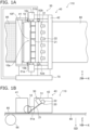
- FIG. 1A and FIG. 1B are schematic views illustrating a coating apparatus according to a first embodiment.
- FIG. 1A is a top view.
- FIG. 1B is a side view. In FIG. 1B , some elements are omitted in order to make the figure easier to see.
- FIG. 2 is a schematic side view illustrating the coating apparatus according to the first embodiment.
- a coating apparatus 110 includes a coating bar 10 and a plurality of nozzles 21.
- the plurality of nozzles 21 may be included in the nozzle part 20.
- the coating bar 10 is configured to face a member to be coated 80.
- the plurality of nozzles 21 are configured to face the coating bar 10. As shown in FIG. 2 , the plurality of nozzles 21 are configured to supply a liquid 84 toward the coating bar 10.
- the plurality of nozzles 21 are arranged along a first direction.
- the first direction is, for example, a Y-axis direction.
- One direction perpendicular to the Y-axis direction is defined as an X-axis direction.
- the direction perpendicular to the Y-axis direction and the X-axis direction is defined as a Z-axis direction.
- the coating bar 10 extends, for example, along the Y-axis direction.
- a meniscus 84M of the liquid 84 can be formed between the member to be coated 80 and the coating bar 10.
- a coating film 85 made of the liquid 84 is formed on the member to be coated 80.
- solidifying (for example, drying) the coating film 85 the desired film (solid film) can be obtained.
- the number of the plurality of nozzles 21 is 3 or more. As a result, the coating film 85 having a large area can be stably formed.
- the number of the plurality of nozzles 21 is 6. In embodiments, the number may be any integer greater than or equal to 3.
- a surface 10F of the coating bar 10 is provided with unevenness.
- the unevenness can be formed by, for example, a method such as sandblasting.
- the arithmetic mean roughness Ra of the unevenness can be controlled.
- a maximum height Rz of the unevenness can be controlled.
- the conditions for forming the unevenness include, for example, at least one of the size of the particles used (for example, the average diameter), the type of particles, and the treatment time.
- the arithmetic mean roughness Ra of the surface 10F of the coating bar 10 is, for example, not less than 0.5 ⁇ m and not more than 10 ⁇ m.
- the thickness unevenness of the formed coating film 85 can be reduced.
- the wettability of the surface 10F is improved by providing the surface 10F of the coating bar 10 with unevenness having an appropriate roughness. It is considered that this is the reason why the coating film 85 having a uniform thickness can be easily obtained.
- FIG. 3A and FIG. 3B are graphs illustrating the characteristics of the coating apparatus.
- the horizontal axis of FIG. 3A is the arithmetic mean roughness Ra of the surface 10F of the coating bar 10.
- the horizontal axis of FIG. 3B is the maximum height Rz of the unevenness on the surface 10F of the coating bar 10.
- the vertical axis of these figures is the thickness unevenness Dz of the solid film obtained by the coating film 85.
- the thickness unevenness Dz is a relative standard deviation (%).
- a small thickness unevenness Dz can be obtained in the range where the arithmetic mean roughness Ra is about not less than 3 ⁇ m and not more than about 8 ⁇ m.
- the arithmetic mean roughness Ra is not less than 0.5 ⁇ m and not more than 10 ⁇ m
- a small thickness unevenness Dz can be obtained.
- the arithmetic mean roughness Ra is less than 0.5 ⁇ m
- the thickness unevenness Dz is large.
- the coating bar 10 is likely to become dirty.
- the arithmetic mean roughness Ra is larger than 10 ⁇ m, it becomes difficult to clean the coating bar 10.
- the arithmetic mean roughness Ra is, for example, preferably not less than 2 ⁇ m and not more than 6 ⁇ m.
- tips of the two nozzles 21 are on one straight line.
- This straight line is, for example, along the extending direction of the coating bar 10.
- the relative positions between each of the two nozzles 21 and the coating bar 10 are likely to be uniform. Therefore, the appropriate range of the degree of unevenness (for example, arithmetic mean roughness Ra) on the surface 10F of the coating bar 10 is relatively wide.
- the number of the plurality of nozzles 21 is 3 or more.
- a coating film 85 having a large area can be obtained.
- the arithmetic mean roughness Ra in an appropriate range can effectively reduce the thickness unevenness Dz.
- a film of liquid 84 can be stably formed on the surface of the coating bar 10. As a result, it is considered that a small thickness unevenness Dz can be obtained.
- a small thickness unevenness Dz can be obtained in the range where the maximum height Rz is not less than about 10 ⁇ m about not more than 30 ⁇ m. Practically, when the maximum height Rz is not less than 5 ⁇ m and not more than 50 ⁇ m, a small thickness unevenness Dz can be obtained. When the maximum height Rz is smaller than 5 ⁇ m, for example, the capillary effect tends to be small. If the maximum height Rz is larger than 50 ⁇ m, for example, the coating bar 10 is likely to be contaminated. If the maximum height Rz is larger than 50 ⁇ m, for example, the member to be coated 80 is likely to be scratched.
- the unevenness of the coating bar 10 may be formed by, for example, sandblasting.
- sandblasting uniform unevenness can be formed on the curved surface of the coating bar 10.
- oxidation of the surface 10F of the coating bar 10 is promoted.
- the coating bar 10 includes, for example, a metal.
- the coating bar 10 includes, for example, at least one selected from the group consisting of stainless steel, titanium and aluminum.
- the coating bar 10 includes stainless steel, high durability can be easily obtained.
- the coating bar 10 includes stainless steel, the cost can be easily reduced.
- the surface 10F of the coating bar 10 may include an oxide.
- the surface 10F may include, for example, aluminum oxide or the like. For example, good wettability can be easily obtained.
- the contact angle of the surface 10F of the coating bar 10 with water is, for example, less than 90 degrees.
- the highly hydrophilic surface 10F makes it easier to obtain a more uniform coating film 85.
- the contact angle may be 50 degrees or less.
- the contact angle may be 10 degrees or less.
- the plurality of nozzles 21 may be in contact with the coating bar 10.
- a position of at least a part of the plurality of nozzles 21 is higher than a position of the coating bar 10. Due to the influence of gravity, a more stable meniscus 84M can be easily obtained.
- the plurality of nozzles 21 may come into contact with the coating bar 10 from the upper part of the coating bar 10.
- the liquid 84 can be easily and stably supplied.
- the surface 10F of the coating bar 10 includes a first region 10a, a second region 10b, and a third region 10c.
- the first region 10a is between the second region 10b and the third region 10c.
- the first region 10a is a region facing the plurality of nozzles 21.
- the second region 10b and the third region 10c are regions that do not face the plurality of nozzles 21.
- the second region 10b and the third region 10c may include, for example, the end portion of the coating bar 10 in the Y-axis direction.
- the arithmetic mean roughness Ra in the first region 10a is not less than 0.5 ⁇ m and not more than 10 ⁇ m.
- the arithmetic mean roughness Ra in the second region 10b and the third region 10c is less than 0.5 ⁇ m or more than 10 ⁇ m.
- the plurality of nozzles 21 are connected to a base 22.
- a supply pipe 25 is connected to the base 22.
- the liquid 84 is supplied to the base 22 via the supply pipe 25.
- the liquid 84 is discharged from the plurality of nozzles 21.
- the nozzle 21 is held by the first member 31 and the third member 33.
- the nozzle 21 is located between the first member 31 and the third member 33.
- the third member 33 is fixed to the first member 31 by the second member 32.
- an elastic member 35 is provided between the third member 33 and the second member 32.
- the elastic member 35 makes it easier to stabilize the positions of the plurality of nozzles 21.
- the nozzle part 20, the first member 31, the second member 32, the third member 33, and the elastic member 35 may be included in the head portion 30.
- the configuration relating to the holding of the plurality of nozzles 21 may be variously modified.
- the coating apparatus 110 may include a position control part 40.
- the position control part 40 is configured to control the relative position between the plurality of nozzles 21 and the coating bar 10.
- the position control part 40 may include a first holding portion 41 and a second holding portion 42.
- the first holding portion 41 holds the coating bar 10.
- the second holding portion 42 holds the plurality of nozzles 21.
- the first member 31 is held by the second holding portion 42.
- the plurality of nozzles 21 held by the first member 31 are held by the second holding portion 42.
- At least one of the first holding portion 41 and the second holding portion 42 may be possible apply a stress having at least one of an orientation from the coating bar 10 to the plurality of nozzles 21 and an orientation from the plurality of nozzles 21 to the coating bar 10 to at least one of the coating bar 10 and the plurality of nozzles 21.
- an interval between the plurality of nozzles 21 may be variable.
- the interval corresponds to the distance along the Y-axis direction illustrated in FIG. 1A .
- the coating apparatus 110 may include the first sensors 51a and 51b.
- the first sensors 51a and 51b detect, for example, a distance between the coating bar 10 and the member to be coated 80.
- the coating apparatus 110 may include a control part 70.
- the control part 70 obtains, for example, a detection results of the first sensors 51a and 51b, and controls the position control part 40 (for example, the first holding portion 41) based on the detection results.
- the control part 70 appropriately controls the distance between the coating bar 10 and the member to be coated 80.
- the first sensors 51a and 51b include, for example, an optical element.
- the first sensors 51a and 51b may include, for example, a camera.
- the coating apparatus 110 may include a member to be coated holding portion 66.
- the member to be coated holding portion 66 holds the member to be coated 80.
- the member to be coated holding portion 66 can move the member to be coated 80 relative to the coating bar 10.
- the member to be coated holding portion 66 is, for example, a transporting portion.
- the member to be coated holding portion 66 is, for example, a roller.
- the member to be coated holding portion 66 can convey the member to be coated 80 along the direction crossing the orientation of the gravity GD.
- the orientation of gravity GD is, for example, along the Z-axis direction.
- the crossing direction is, for example, the X-axis direction.
- the transport direction (movement direction 88) is along the horizontal direction.
- the extending direction of the plurality of nozzles 21 is, for example, close to the horizontal direction. Alignment is easy. For example, the dripping of the liquid 84 can be suppressed.
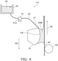
- FIG. 4 is a schematic view illustrating the coating apparatus according to the first embodiment.
- the coating apparatus 110 includes the member to be coated holding portion 66.
- the member to be coated holding portion 66 holds the member to be coated 80.
- the member to be coated holding portion 66 moves the member to be coated 80 relative to the coating bar 10.
- the member to be coated holding portion 66 can convey the member to be coated 80 in the direction 88a including a component opposite to the orientation of the gravity GD. For example, gravity is applied to the meniscus 84M. Even in high-speed coating, it is easy to obtain a uniform coating film 85.
- the moving direction of the member to be coated 80 can be variously deformed.
- the angle between the direction of movement and the orientation (direction) of gravity may be, for example, ⁇ 30 ° or less.
- the coating apparatus 110 may include a supply part 61.
- the supply part 61 is configured to supply the liquid 84 to the plurality of nozzles 21.
- the supply part 61 includes, for example, a pump 61p.
- a tank 65 for storing the liquid 84 is provided.
- the supply part 61 is connected to the tank 65.
- the supply part 61 is connected to the plurality of nozzles 21 by the supply pipe 25.
- the liquid 84 is supplied from the supply part 61 to the plurality of nozzles 21.
- the liquid 84 is supplied from the plurality of nozzles 21 toward the coating bar 10.
- the supply part 61 may include a plurality of pumps 61p.
- the number of the plurality of nozzles 21 is, for example, an integral multiple of the number of the plurality of pumps 61p.
- the number of the plurality of nozzles 21 may be 12 or more.
- the number of the plurality of nozzles 21 is, for example, 12, 16 or 20.
- the supply pipe 25 connecting the pump 61p and the plurality of nozzles 21 may have a branched structure.
- the number of supply pipes 25 is, for example, 2, 4, or 8.
- the liquid 84 can be stably and uniformly supplied with a small number of pumps 61p.
- the pump 61p may include, for example, a diaphragm pump.
- the diaphragm pump can be applied to a liquid 84 including various solvents.
- FIG. 5 is a schematic view illustrating the coating apparatus according to the first embodiment.
- the member to be coated holding portion 66 includes a first holding mechanism 66a and a second holding mechanism 66b.
- the member to be coated 80 includes a roll-shaped film.
- the first holding mechanism 66a holds a first portion 80a of the roll-shaped film (member to be coated 80).
- the second holding mechanism 66b holds a second portion 80b of the roll-shaped film (member to be coated 80).
- the first holding mechanism 66a and the second holding mechanism 66b are, for example, rollers. Continuous coating to roll film is possible.
- At least a part of the cross section of the coating bar 10 in a plane (for example, the X-X plane) crossing the first direction (Y-axis direction) in which the plurality of nozzles 21 are arranged may be circular.
- the cross section may be a circle, an ellipse, a trapezoid, or the like. When the cross section is circular, the coating head can be easily manufactured. When the cross section is circular, it is easy to maintain a uniform distance between the member to be coated 80 and the coating bar 10.
- a part of the cross section may be curved, and the other part of the cross section may be straight.
- the plurality of nozzles 21 may be needle-shaped. In the needle shape, the length is longer than the diameter.
- the openings of the plurality of nozzles 21 may be substantially 90 degrees with respect to the extending direction of the plurality of nozzles 21. In this case, even when the plurality of nozzles 21 rotate, the relative positional relationship between the openings (ends) of the plurality of nozzles 21 and the coating bar 10 is unlikely to change. For example, it is easy to suppress scratches on the coating bar 10 caused by at least one of the plurality of nozzles 21.
- the length of the plurality of nozzles 21 may be, for example, not less than 2 cm and not more than 10 cm.
- the inner diameter of the plurality of nozzles 21 is, for example, not less than 0.2 and mot more than 2 mm.
- a collection unit for collecting the liquid 84 may be provided.
- a drying portion capable of solidifying the coating film 85 may be provided.
- the drying portion may include, for example, a heater, a blower, an infrared irradiation portion, or the like.
- a cleaning portion capable of cleaning the coating bar 10 may be provided.
- the cleaning portion may include a mechanism for spraying or radiating a solvent.
- the solvent may include, for example, water.
- the cleaning unit may include a mechanism for applying ultrasonic waves.
- a film included in a solar cell may be formed by the coating apparatus according to the embodiment.
- the member to be coated 80 may be a roll-shaped film.
- the member to be coated 80 is a roll-shaped PET film.
- the width (length in the Y-axis direction) of the PET film is 300 mm.
- a light-transmitting conductive film is formed on a roll-shaped film by a roll-to-roll sputtering device.
- the conductive film is an ITO / Ag alloy / ITO laminated film.
- the conductive film is patterned into a desired shape.
- the length of one of the plurality of nozzles 21 is about 50 mm.
- the plurality of nozzles 21 include stainless steel.
- the inner diameter of each of the plurality of nozzles 21 is 0.8 mm.
- the plurality of nozzles 21 are fixed to the first member 31 by the second member 32 by using the third member 33 and the elastic member 35.
- the supply pipe 25 is connected to the bases 22 of the plurality of nozzles 21.
- a PEDOT / PSS aqueous dispersion is used as the liquid 84. From this liquid 84, for example, a hole-transport layer of a solar cell can be produced.
- the cross-sectional shape of the coating bar 10 is substantially trapezoidal.
- the bottom of the cross-sectional shape of the coating bar 10 is an arc shape having a curvature of 80 mm.
- the length of the coating bar 10 in the Y-axis direction is 300 mm.
- the material of the coating bar 10 is SUS303.
- the liquid 84 is coated using the coating bar 10 under various conditions. As a result, the coating film 85 is obtained. The coating film 85 is dried to obtain the desired film. Thickness unevenness Dz is evaluated from the distribution of the absorbance of the film.
- the arithmetic mean roughness Ra of the surface 10F of the coating bar 10 is 3.2 ⁇ m.
- the maximum height Rz of the unevenness is 20 ⁇ m.
- the surface 10F is visually uniform.
- the contact angle with water is about 5 degrees.
- the thickness unevenness Dz is 10% or less.
- the surface of the coating bar 10 is not sandblasted.
- the arithmetic mean roughness Ra is 0.4 ⁇ m.
- the maximum height Rz of the unevenness is 10 ⁇ m.
- the thickness unevenness Dz is 20% or more.
- the arithmetic mean roughness Ra is 12 ⁇ m.
- the maximum height Rz of the unevenness is 70 ⁇ m.
- the thickness unevenness Dz is 15% or more.
- the coating bar 10 is easily contaminated and difficult to clean.
- the arithmetic mean roughness Ra is 0.006 ⁇ m.
- the maximum height Rz of the unevenness is 10 ⁇ m.
- the thickness unevenness Dz is 30% or more.
- the arithmetic mean roughness Ra is 4.3 ⁇ m.
- the maximum height Rz of the unevenness is 25 ⁇ m.
- the thickness unevenness Dz is 10% or less.
- the material of the coating bar 10 is stainless steel.
- the material of the coating bar 10 is aluminum.
- the arithmetic mean roughness Ra is 8 ⁇ m.
- the maximum height Rz of the unevenness is 30 ⁇ m.
- the thickness unevenness Dz is 12% or less.
- a second embodiment relates to a coating method.
- the liquid 84 is coated on the member to be coated 80 by any coating apparatus according to the first embodiment.
- a uniform coating film 85 can be formed.
- a low-cost solar cell can be obtained by forming a layer contained in the solar cell by coating.
- roll-to-roll coating provides a uniform coating film.
- the meniscus 84M is formed between the coating bar 10 and the member to be coated 80.
- a uniform coating film 85 can be obtained by the coating bar 10 having an appropriate surface condition.
- the embodiments may include the following configurations (for example, technical proposals).
- a coating apparatus comprising:
- the coating apparatus according to configuration 1 or 2, wherein the coating bar includes at least one selected from the group consisting of stainless steel, titanium and aluminum.
- the coating apparatus according to any one of configurations 1-3, wherein the surface includes oxides.
- a contact angle of the surface with water is less than 90 degrees.
- the coating apparatus according to any one of configurations 1-6, wherein the plurality of nozzles are in contact with the coating bar.
- the coating apparatus according to any one of configurations 1-8, further comprising a member to be coated holding portion configured to hold the member to be coated and to move the member to be coated relative to the coating bar, and the member to be coated holding portion is configured to convey the member to be coated in a direction including a component opposite to an orientation of a gravity.
- the coating apparatus according to any one of configurations 1-8, further comprising a member to be coated holding portion configured to hold the member to be coated and to move the member to be coated relative to the coating bar, and the member to be coated holding portion is configured to convey the member to be coated along a first direction crossing an orientation of a gravity.
- the coating apparatus according to any one of configurations 9-11, further comprising a supply part to supply the liquid to the plurality of nozzles.
- the coating apparatus according to any one of configurations 1-1, further comprising a position control part configured to control a relative position between the plurality of nozzles and the coating bar.
- a coating method comprising; coating the liquid to the member to be coated by the coating apparatus according to any one of configurations 1-19.
- a coating apparatus and a coating method capable of forming a uniform coating film are provided.
Landscapes
- Coating Apparatus (AREA)
- Application Of Or Painting With Fluid Materials (AREA)
Abstract

Description
- Embodiments of the invention relate to a coating apparatus and a coating method.
- There is a coating apparatus that coats liquid using a coating bar. A coating apparatus capable of forming a uniform coating film is desired.
- [Patent Document 1]
JP 2016-174992 A - The embodiments of the invention provide a coating apparatus and a coating method, in which a uniform coating film can be formed.
- According to one embodiment of the invention, a coating apparatus includes a coating bar configured to face a member to be coated, and a plurality of nozzles configured to supply a liquid toward the coating bar. A number of the nozzles is 3 or more. An arithmetic mean roughness Ra of at least a part of a surface of the coating bar is not less than 0.5 µm and not more than 10 µm.
-
- [
FIG. 1 ]
FIG. 1A and FIG. 1B are schematic views illustrating a coating apparatus according to a first embodiment. - [
FIG. 2 ]
FIG. 2 is a schematic side view illustrating the coating apparatus according to the first embodiment. - [
FIG. 3 ]
FIG. 3A and FIG. 3B are graphs illustrating the characteristics of the coating apparatus. - [
FIG. 4 ]
FIG. 4 is a schematic view illustrating the coating apparatus according to the first embodiment. - [
FIG. 5 ]
FIG. 5 is a schematic view illustrating the coating apparatus according to the first embodiment. - Embodiments of the invention will be described below in detail with reference to the accompanying drawings.
- The drawings are schematic and conceptual; and the relationships between the thickness and width of portions, the proportions of sizes among portions, etc., are not necessarily the same as the actual values. The dimensions and proportions may be illustrated differently among drawings, even for identical portions.
- In the specification and drawings, components similar to those described previously in an antecedent drawing are marked with like reference numerals, and a detailed description is omitted as appropriate.
-
FIG. 1A and FIG. 1B are schematic views illustrating a coating apparatus according to a first embodiment. -
FIG. 1A is a top view.FIG. 1B is a side view. InFIG. 1B , some elements are omitted in order to make the figure easier to see. -
FIG. 2 is a schematic side view illustrating the coating apparatus according to the first embodiment. - As shown in
FIG. 1A , acoating apparatus 110 according to the embodiment includes acoating bar 10 and a plurality ofnozzles 21. The plurality ofnozzles 21 may be included in thenozzle part 20. - As shown in
FIG. 2 , thecoating bar 10 is configured to face a member to be coated 80. - As shown in
FIG. 1A andFIG. 2 , the plurality ofnozzles 21 are configured to face thecoating bar 10. As shown inFIG. 2 , the plurality ofnozzles 21 are configured to supply aliquid 84 toward thecoating bar 10. - As shown in
FIG. 1A , the plurality ofnozzles 21 are arranged along a first direction. The first direction is, for example, a Y-axis direction. One direction perpendicular to the Y-axis direction is defined as an X-axis direction. The direction perpendicular to the Y-axis direction and the X-axis direction is defined as a Z-axis direction. Thecoating bar 10 extends, for example, along the Y-axis direction. - As shown in
FIG. 2 , ameniscus 84M of theliquid 84 can be formed between the member to be coated 80 and thecoating bar 10. When themeniscus 84M comes into contact with the member to be coated 80, acoating film 85 made of theliquid 84 is formed on the member to be coated 80. By solidifying (for example, drying) thecoating film 85, the desired film (solid film) can be obtained. For example, by moving the member to be coated 80 along the movingdirection 88, it is possible to form thecoating film 85 having a large area on the member to be coated 80. - In the embodiment, the number of the plurality of
nozzles 21 is 3 or more. As a result, thecoating film 85 having a large area can be stably formed. In the example ofFIG. 1A , the number of the plurality ofnozzles 21 is 6. In embodiments, the number may be any integer greater than or equal to 3. - In the embodiment, a
surface 10F of thecoating bar 10 is provided with unevenness. The unevenness can be formed by, for example, a method such as sandblasting. By controlling the conditions for forming the unevenness, the arithmetic mean roughness Ra of the unevenness can be controlled. By controlling the conditions for forming the unevenness, a maximum height Rz of the unevenness can be controlled. When a technique such as sandblasting is used, the conditions for forming the unevenness include, for example, at least one of the size of the particles used (for example, the average diameter), the type of particles, and the treatment time. - In the embodiment, the arithmetic mean roughness Ra of the
surface 10F of thecoating bar 10 is, for example, not less than 0.5 µm and not more than 10 µm. As a result, it was found that the thickness unevenness of the formedcoating film 85 can be reduced. For example, the wettability of thesurface 10F is improved by providing thesurface 10F of thecoating bar 10 with unevenness having an appropriate roughness. It is considered that this is the reason why thecoating film 85 having a uniform thickness can be easily obtained. -
FIG. 3A and FIG. 3B are graphs illustrating the characteristics of the coating apparatus. - The horizontal axis of
FIG. 3A is the arithmetic mean roughness Ra of thesurface 10F of thecoating bar 10. The horizontal axis ofFIG. 3B is the maximum height Rz of the unevenness on thesurface 10F of thecoating bar 10. The vertical axis of these figures is the thickness unevenness Dz of the solid film obtained by thecoating film 85. The thickness unevenness Dz is a relative standard deviation (%). - As shown in
FIG. 3A , a small thickness unevenness Dz can be obtained in the range where the arithmetic mean roughness Ra is about not less than 3 µm and not more than about 8 µm. Practically, when the arithmetic mean roughness Ra is not less than 0.5 µm and not more than 10 µm, a small thickness unevenness Dz can be obtained. When the arithmetic mean roughness Ra is less than 0.5 µm, the thickness unevenness Dz is large. If the arithmetic mean roughness Ra is larger than 10 µm, thecoating bar 10 is likely to become dirty. If the arithmetic mean roughness Ra is larger than 10 µm, it becomes difficult to clean thecoating bar 10. The arithmetic mean roughness Ra is, for example, preferably not less than 2 µm and not more than 6 µm. - It is considered that good wettability can be obtained on the
surface 10F of thecoating bar 10 by providing the unevenness of the arithmetic mean roughness Ra of not less than 0.5 µm and not more than 10 µm. As a result, it is considered that the thickness unevenness Dz can be reduced. - When the number of the plurality of
nozzles 21 is 2, tips of the twonozzles 21 are on one straight line. This straight line is, for example, along the extending direction of thecoating bar 10. The relative positions between each of the twonozzles 21 and thecoating bar 10 are likely to be uniform. Therefore, the appropriate range of the degree of unevenness (for example, arithmetic mean roughness Ra) on thesurface 10F of thecoating bar 10 is relatively wide. - On the other hand, as already described, in the embodiment, the number of the plurality of
nozzles 21 is 3 or more. As a result, acoating film 85 having a large area can be obtained. When the number of the plurality ofnozzles 21 is 3 or more, it becomes difficult to make the relative positions between each of the plurality ofnozzles 21 and thecoating bar 10 uniform. In such a situation, the arithmetic mean roughness Ra in an appropriate range can effectively reduce the thickness unevenness Dz. With an appropriate range of arithmetic mean roughness Ra, for example, due to the capillary effect, a film ofliquid 84 can be stably formed on the surface of thecoating bar 10. As a result, it is considered that a small thickness unevenness Dz can be obtained. - As shown in
FIG. 3B , a small thickness unevenness Dz can be obtained in the range where the maximum height Rz is not less than about 10 µm about not more than 30 µm. Practically, when the maximum height Rz is not less than 5 µm and not more than 50 µm, a small thickness unevenness Dz can be obtained. When the maximum height Rz is smaller than 5 µm, for example, the capillary effect tends to be small. If the maximum height Rz is larger than 50 µm, for example, thecoating bar 10 is likely to be contaminated. If the maximum height Rz is larger than 50 µm, for example, the member to be coated 80 is likely to be scratched. - The unevenness of the
coating bar 10 may be formed by, for example, sandblasting. By the sandblasting, uniform unevenness can be formed on the curved surface of thecoating bar 10. For example, oxidation of thesurface 10F of thecoating bar 10 is promoted. For example, it is easy to improve the wettability. For example, it is easy to obtain high hydrophilicity. - In the embodiment, the
coating bar 10 includes, for example, a metal. Thecoating bar 10 includes, for example, at least one selected from the group consisting of stainless steel, titanium and aluminum. When thecoating bar 10 includes stainless steel, high durability can be easily obtained. When thecoating bar 10 includes stainless steel, the cost can be easily reduced. - The
surface 10F of thecoating bar 10 may include an oxide. Thesurface 10F may include, for example, aluminum oxide or the like. For example, good wettability can be easily obtained. - The contact angle of the
surface 10F of thecoating bar 10 with water is, for example, less than 90 degrees. The highlyhydrophilic surface 10F makes it easier to obtain a moreuniform coating film 85. The contact angle may be 50 degrees or less. The contact angle may be 10 degrees or less. - In the embodiment, the plurality of
nozzles 21 may be in contact with thecoating bar 10. - As shown in
FIG. 2 , a position of at least a part of the plurality ofnozzles 21 is higher than a position of thecoating bar 10. Due to the influence of gravity, a morestable meniscus 84M can be easily obtained. For example, the plurality ofnozzles 21 may come into contact with thecoating bar 10 from the upper part of thecoating bar 10. For example, the liquid 84 can be easily and stably supplied. - As shown in
FIG. 1A , thesurface 10F of thecoating bar 10 includes afirst region 10a, asecond region 10b, and athird region 10c. In the first direction (for example, the Y-axis direction) in which the plurality ofnozzles 21 are arranged, thefirst region 10a is between thesecond region 10b and thethird region 10c. Thefirst region 10a is a region facing the plurality ofnozzles 21. Thesecond region 10b and thethird region 10c are regions that do not face the plurality ofnozzles 21. Thesecond region 10b and thethird region 10c may include, for example, the end portion of thecoating bar 10 in the Y-axis direction. - The arithmetic mean roughness Ra in the
first region 10a is not less than 0.5 µm and not more than 10 µm. The arithmetic mean roughness Ra in thesecond region 10b and thethird region 10c is less than 0.5 µm or more than 10 µm. By appropriately setting the arithmetic mean roughness Ra in thefirst region 10a used for coating, a small thickness unevenness Dz can be obtained. For example, in thesecond region 10b and thethird region 10c corresponding to the end portion, surface characteristics different from the arithmetic mean roughness Ra in thefirst region 10a are applied. As a result, the adhesion of the liquid 84 to the unnecessary portion can be suppressed. The efficiency of using the liquid 84 is improved. - As shown in
FIG. 2 , in this example, the plurality ofnozzles 21 are connected to abase 22. Asupply pipe 25 is connected to thebase 22. The liquid 84 is supplied to thebase 22 via thesupply pipe 25. The liquid 84 is discharged from the plurality ofnozzles 21. - As shown in
FIG. 2 , in this example, thenozzle 21 is held by thefirst member 31 and thethird member 33. Thenozzle 21 is located between thefirst member 31 and thethird member 33. Thethird member 33 is fixed to thefirst member 31 by thesecond member 32. In this example, anelastic member 35 is provided between thethird member 33 and thesecond member 32. Theelastic member 35 makes it easier to stabilize the positions of the plurality ofnozzles 21. Thenozzle part 20, thefirst member 31, thesecond member 32, thethird member 33, and theelastic member 35 may be included in thehead portion 30. In the embodiment, the configuration relating to the holding of the plurality ofnozzles 21 may be variously modified. - As shown in
FIG. 1A , thecoating apparatus 110 may include aposition control part 40. The position controlpart 40 is configured to control the relative position between the plurality ofnozzles 21 and thecoating bar 10. - As shown in
FIG. 1A and FIG. 1B , for example, the position controlpart 40 may include a first holdingportion 41 and asecond holding portion 42. Thefirst holding portion 41 holds thecoating bar 10. Thesecond holding portion 42 holds the plurality ofnozzles 21. For example, thefirst member 31 is held by the second holdingportion 42. As a result, the plurality ofnozzles 21 held by thefirst member 31 are held by the second holdingportion 42. - At least one of the first holding
portion 41 and the second holdingportion 42 may be possible apply a stress having at least one of an orientation from thecoating bar 10 to the plurality ofnozzles 21 and an orientation from the plurality ofnozzles 21 to thecoating bar 10 to at least one of thecoating bar 10 and the plurality ofnozzles 21. - In the embodiment, an interval between the plurality of
nozzles 21 may be variable. The interval corresponds to the distance along the Y-axis direction illustrated inFIG. 1A . - As shown in
FIG. 1A , thecoating apparatus 110 may include thefirst sensors first sensors coating bar 10 and the member to be coated 80. - As shown in
FIG. 1A , thecoating apparatus 110 may include acontrol part 70. Thecontrol part 70 obtains, for example, a detection results of thefirst sensors control part 70 appropriately controls the distance between thecoating bar 10 and the member to be coated 80. Thefirst sensors first sensors - As shown in
FIG. 1B , thecoating apparatus 110 may include a member to be coated holdingportion 66. The member to be coated holdingportion 66 holds the member to be coated 80. The member to be coated holdingportion 66 can move the member to be coated 80 relative to thecoating bar 10. The member to be coated holdingportion 66 is, for example, a transporting portion. The member to be coated holdingportion 66 is, for example, a roller. In this example, the member to be coated holdingportion 66 can convey the member to be coated 80 along the direction crossing the orientation of the gravity GD. The orientation of gravity GD is, for example, along the Z-axis direction. The crossing direction is, for example, the X-axis direction. - For example, the transport direction (movement direction 88) is along the horizontal direction. In this case, the extending direction of the plurality of
nozzles 21 is, for example, close to the horizontal direction. Alignment is easy. For example, the dripping of the liquid 84 can be suppressed. -
FIG. 4 is a schematic view illustrating the coating apparatus according to the first embodiment. - As shown in
FIG. 4 , thecoating apparatus 110 includes the member to be coated holdingportion 66. The member to be coated holdingportion 66 holds the member to be coated 80. The member to be coated holdingportion 66 moves the member to be coated 80 relative to thecoating bar 10. In this example, the member to be coated holdingportion 66 can convey the member to be coated 80 in the direction 88a including a component opposite to the orientation of the gravity GD. For example, gravity is applied to themeniscus 84M. Even in high-speed coating, it is easy to obtain auniform coating film 85. - In the embodiment, the moving direction of the member to be coated 80 can be variously deformed. The angle between the direction of movement and the orientation (direction) of gravity may be, for example, ± 30 ° or less.
- As shown in
FIG. 4 , thecoating apparatus 110 may include asupply part 61. Thesupply part 61 is configured to supply the liquid 84 to the plurality ofnozzles 21. Thesupply part 61 includes, for example, apump 61p. In this example, atank 65 for storing the liquid 84 is provided. Thesupply part 61 is connected to thetank 65. Thesupply part 61 is connected to the plurality ofnozzles 21 by thesupply pipe 25. The liquid 84 is supplied from thesupply part 61 to the plurality ofnozzles 21. The liquid 84 is supplied from the plurality ofnozzles 21 toward thecoating bar 10. - The
supply part 61 may include a plurality ofpumps 61p. The number of the plurality ofnozzles 21 is, for example, an integral multiple of the number of the plurality ofpumps 61p. - In the embodiment, the number of the plurality of
nozzles 21 may be 12 or more. The number of the plurality ofnozzles 21 is, for example, 12, 16 or 20. Thesupply pipe 25 connecting thepump 61p and the plurality ofnozzles 21 may have a branched structure. The number ofsupply pipes 25 is, for example, 2, 4, or 8. For example, when the number ofsupply pipes 25 is 4, the liquid 84 can be stably and uniformly supplied with a small number ofpumps 61p. - In the embodiment, the
pump 61p may include, for example, a diaphragm pump. The diaphragm pump can be applied to a liquid 84 including various solvents. -
FIG. 5 is a schematic view illustrating the coating apparatus according to the first embodiment. - As shown in
FIG. 5 , in acoating apparatus 111, the member to be coated holdingportion 66 includes afirst holding mechanism 66a and asecond holding mechanism 66b. In this example, the member to be coated 80 includes a roll-shaped film. Thefirst holding mechanism 66a holds afirst portion 80a of the roll-shaped film (member to be coated 80). Thesecond holding mechanism 66b holds asecond portion 80b of the roll-shaped film (member to be coated 80). Thefirst holding mechanism 66a and thesecond holding mechanism 66b are, for example, rollers. Continuous coating to roll film is possible. - At least a part of the cross section of the
coating bar 10 in a plane (for example, the X-X plane) crossing the first direction (Y-axis direction) in which the plurality ofnozzles 21 are arranged may be circular. The cross section may be a circle, an ellipse, a trapezoid, or the like. When the cross section is circular, the coating head can be easily manufactured. When the cross section is circular, it is easy to maintain a uniform distance between the member to be coated 80 and thecoating bar 10. A part of the cross section may be curved, and the other part of the cross section may be straight. - In the embodiment, the plurality of
nozzles 21 may be needle-shaped. In the needle shape, the length is longer than the diameter. The openings of the plurality ofnozzles 21 may be substantially 90 degrees with respect to the extending direction of the plurality ofnozzles 21. In this case, even when the plurality ofnozzles 21 rotate, the relative positional relationship between the openings (ends) of the plurality ofnozzles 21 and thecoating bar 10 is unlikely to change. For example, it is easy to suppress scratches on thecoating bar 10 caused by at least one of the plurality ofnozzles 21. - The length of the plurality of
nozzles 21 may be, for example, not less than 2 cm and not more than 10 cm. The inner diameter of the plurality ofnozzles 21 is, for example, not less than 0.2 and mot more than 2 mm. - In the embodiment, a collection unit for collecting the liquid 84 may be provided. In the embodiment, a drying portion capable of solidifying the
coating film 85 may be provided. The drying portion may include, for example, a heater, a blower, an infrared irradiation portion, or the like. - In the embodiment, a cleaning portion capable of cleaning the
coating bar 10 may be provided. The cleaning portion may include a mechanism for spraying or radiating a solvent. The solvent may include, for example, water. The cleaning unit may include a mechanism for applying ultrasonic waves. - For example, a film included in a solar cell may be formed by the coating apparatus according to the embodiment. For example, the member to be coated 80 may be a roll-shaped film.
- The following is an example of the experimental results. In the experiment, the member to be coated 80 is a roll-shaped PET film. The width (length in the Y-axis direction) of the PET film is 300 mm. A light-transmitting conductive film is formed on a roll-shaped film by a roll-to-roll sputtering device. The conductive film is an ITO / Ag alloy / ITO laminated film. The conductive film is patterned into a desired shape.
- The length of one of the plurality of
nozzles 21 is about 50 mm. The plurality ofnozzles 21 include stainless steel. The inner diameter of each of the plurality ofnozzles 21 is 0.8 mm. The plurality ofnozzles 21 are fixed to thefirst member 31 by thesecond member 32 by using thethird member 33 and theelastic member 35. Thesupply pipe 25 is connected to thebases 22 of the plurality ofnozzles 21. - In the experiment, a PEDOT / PSS aqueous dispersion is used as the liquid 84. From this liquid 84, for example, a hole-transport layer of a solar cell can be produced.
- The cross-sectional shape of the
coating bar 10 is substantially trapezoidal. The bottom of the cross-sectional shape of thecoating bar 10 is an arc shape having a curvature of 80 mm. The length of thecoating bar 10 in the Y-axis direction is 300 mm. The material of thecoating bar 10 is SUS303. - In the experiment, sandblasting is performed on the bottom surface of the
coating bar 10 and the surface next to the bottom surface. As a result, unevenness is formed on thesurface 10F of thecoating bar 10. Depending on the treatment conditions, various characteristics can be obtained on thesurface 10F of thecoating bar 10. Alternatively, various unevenness can be formed on thesurface 10F by various surface treatments. - The liquid 84 is coated using the
coating bar 10 under various conditions. As a result, thecoating film 85 is obtained. Thecoating film 85 is dried to obtain the desired film. Thickness unevenness Dz is evaluated from the distribution of the absorbance of the film. - In a first sample, the arithmetic mean roughness Ra of the
surface 10F of thecoating bar 10 is 3.2 µm. The maximum height Rz of the unevenness is 20 µm. Thesurface 10F is visually uniform. On thesurface 10F, the contact angle with water is about 5 degrees. In the first sample, the thickness unevenness Dz is 10% or less. - In a second sample, the surface of the
coating bar 10 is not sandblasted. In the second sample, the arithmetic mean roughness Ra is 0.4 µm. The maximum height Rz of the unevenness is 10 µm. In the second sample, the thickness unevenness Dz is 20% or more. - In a third sample, the arithmetic mean roughness Ra is 12 µm. The maximum height Rz of the unevenness is 70 µm. In the third sample, the thickness unevenness Dz is 15% or more. In the third sample, the
coating bar 10 is easily contaminated and difficult to clean. - In a fourth sample, the arithmetic mean roughness Ra is 0.006 µm. The maximum height Rz of the unevenness is 10 µm. In the fourth sample, the thickness unevenness Dz is 30% or more.
- In a fifth sample, the arithmetic mean roughness Ra is 4.3 µm. The maximum height Rz of the unevenness is 25 µm. In the fifth sample, the thickness unevenness Dz is 10% or less. In the first sample to the fifth sample, the material of the
coating bar 10 is stainless steel. - In a sixth sample, the material of the
coating bar 10 is aluminum. In the fifth sample, the arithmetic mean roughness Ra is 8 µm. The maximum height Rz of the unevenness is 30 µm. In the fifth sample, the thickness unevenness Dz is 12% or less. - A second embodiment relates to a coating method. In the coating method, the liquid 84 is coated on the member to be coated 80 by any coating apparatus according to the first embodiment. A
uniform coating film 85 can be formed. - For example, there are organic thin-film solar cells using organic semiconductors or organic / inorganic hybrid solar cells. For example, a low-cost solar cell can be obtained by forming a layer contained in the solar cell by coating. According to the embodiment, for example, roll-to-roll coating provides a uniform coating film. In the embodiment, for example, the
meniscus 84M is formed between thecoating bar 10 and the member to be coated 80. Auniform coating film 85 can be obtained by thecoating bar 10 having an appropriate surface condition. - The embodiments may include the following configurations (for example, technical proposals).
- A coating apparatus, comprising:
- a coating bar configured to face a member to be coated; and
- a plurality of nozzles configured to supply a liquid toward the coating bar,
- a number of the nozzles is 3 or more, and
- an arithmetic mean roughness Ra of at least a part of a surface of the coating bar is not less than 0.5 µm and not more than 10 µm.
- The coating apparatus according to configuration 1, wherein
- at least a part of the surface includes unevenness, and
- a maximum height Rz of the unevenness is not less than 5 µm and not more than 50 µm.
- The coating apparatus according to
configuration 1 or 2, wherein the coating bar includes at least one selected from the group consisting of stainless steel, titanium and aluminum. - The coating apparatus according to any one of configurations 1-3, wherein the surface includes oxides.
- The coating apparatus according to any one of configurations 1-4, wherein a contact angle of the surface with water is less than 90 degrees.
- The coating apparatus according to any one of configurations 1-5, wherein a meniscus of the liquid is configured to be formed between the member to be coated and the coating bar.
- The coating apparatus according to any one of configurations 1-6, wherein the plurality of nozzles are in contact with the coating bar.
- The coating apparatus according to any one of configurations 1-7, wherein a position of at least a part of the plurality of nozzles is higher than a position of the coating bar.
- The coating apparatus according to any one of configurations 1-8, further comprising a member to be coated holding portion configured to hold the member to be coated and to move the member to be coated relative to the coating bar, and
the member to be coated holding portion is configured to convey the member to be coated in a direction including a component opposite to an orientation of a gravity. - The coating apparatus according to any one of configurations 1-8, further comprising a member to be coated holding portion configured to hold the member to be coated and to move the member to be coated relative to the coating bar, and
the member to be coated holding portion is configured to convey the member to be coated along a first direction crossing an orientation of a gravity. - The coating apparatus according to
configuration 9 or 10, wherein - the member to be coated includes a roll-shaped film, and
- the member to be coated holding portion includes,
- a first holding mechanism configured to hold a first portion of the roll-shaped film, and
- a second holding mechanism configured to hold a second portion of the roll-shaped film.
- The coating apparatus according to any one of configurations 9-11, further comprising a supply part to supply the liquid to the plurality of nozzles.
- The coating apparatus according to
configuration 12, wherein - the supply part includes a plurality of pumps, and
- a number of the plurality of nozzles is an integral multiple of a number of the plurality of pumps.
- The coating apparatus according to any one of configurations 1-13, wherein a number of the plurality of nozzles is 12 or more.
- The coating apparatus according to any one of configurations 1-14, wherein a cross section of at least a part of the coating bar in a plane crossing a first direction in which the plurality of nozzles are arranged is circular.
- The coating apparatus according to any one of configurations 1-15, wherein
- the surface includes a first region, a second region and a third region,
- in a first direction in which the plurality of nozzles are arranged, the first region is between the second region and the third region,
- an arithmetic mean roughness Ra in the first region is not less than 0.5 µm and not more than 10 µm, and
- an arithmetic mean roughness Ra in the second region and the third region is less than 0.5 µm or more than 10 µm.
- The coating apparatus according to any one of configurations 1-1, further comprising a position control part configured to control a relative position between the plurality of nozzles and the coating bar.
- The coating apparatus according to configuration 17, wherein
- the position control part includes
- a first holding portion configured to hold the coating bar, and
- a second holding portion configured to hold the multiple nozzles, and
- at least one of the first holding portion and the second holding portion is configured to apply a stress having at least one of an orientation from the coating bar to the plurality of nozzles and an orientation from the plurality of nozzles to the coating bar to at least one of the coating bar and the plurality of nozzles.
- The coating apparatus according to any one of configurations 1-18, wherein a spacing between the plurality of nozzles is variable.
- A coating method comprising;
coating the liquid to the member to be coated by the coating apparatus according to any one of configurations 1-19. - According to the embodiment, a coating apparatus and a coating method capable of forming a uniform coating film are provided.
- Hereinabove, exemplary embodiments of the invention are described with reference to specific examples. However, the embodiments of the invention are not limited to these specific examples. For example, one skilled in the art may similarly practice the invention by appropriately selecting specific configurations of components included in coating apparatus such as coating bars, nozzles, etc., from known art. Such practice is included in the scope of the invention to the extent that similar effects thereto are obtained.
- Further, any two or more components of the specific examples may be combined within the extent of technical feasibility and are included in the scope of the invention to the extent that the purport of the invention is included.
- Moreover, all coating apparatuses and coating methods practicable by an appropriate design modification by one skilled in the art based on the coating apparatuses and coating methods described above as embodiments of the invention also are within the scope of the invention to the extent that the purport of the invention is included.
- Various other variations and modifications can be conceived by those skilled in the art within the spirit of the invention, and it is understood that such variations and modifications are also encompassed within the scope of the invention.
- While certain embodiments have been described, these embodiments have been presented by way of example only, and are not intended to limit the scope of the inventions. Indeed, the novel embodiments described herein may be embodied in a variety of other forms; furthermore, various omissions, substitutions and changes in the form of the embodiments described herein may be made without departing from the spirit of the inventions. The accompanying claims and their equivalents are intended to cover such forms or modifications as would fall within the scope and spirit of the invention.
- 10···coating bar, 10F···surface, 10a~10c···first ~ third region, 20···nozzle part, 21····nozzle, 22···base, 25···supply pipe, 30···head portion, 31~33···first ~ third member, 35···elastic member, 40···position control part, 41, 42···first, second holding portion, 51a, 51b···first sensor, 52a, 52b···second sensor, 61···supply part, 61p···pump, 65···tank, 66···member to be coated holding portion, 66a, 66b···first, second holding mechanism, 70···control part, 80··· member to be coated, 80a, 80b···first, second portion, 84···liquid, 84M···meniscus, 85···coating film, 88···moving direction, 88a···orientation, 110, 111···coating apparatus, Dz···thickness unevenness, GD···gravity, Ra···arithmetic mean roughness, Rz···maximum height
Claims (20)
- A coating apparatus, comprising:a coating bar configured to face a member to be coated; anda plurality of nozzles configured to supply a liquid toward the coating bar,a number of the nozzles is 3 or more, andan arithmetic mean roughness Ra of at least a part of a surface of the coating bar is not less than 0.5 µm and not more than 10 µm.
- The coating apparatus according to claim 1, whereinat least a part of the surface includes unevenness, anda maximum height Rz of the unevenness is not less than 5 µm and not more than 50 µm.
- The coating apparatus according to claim 1, wherein the coating bar includes at least one selected from the group consisting of stainless steel, titanium and aluminum.
- The coating apparatus according to claim 1, wherein the surface includes oxides.
- The coating apparatus according to claim 1, wherein a contact angle of the surface with water is less than 90 degrees.
- The coating apparatus according to claim 1, wherein a meniscus of the liquid is configured to be formed between the member to be coated and the coating bar.
- The coating apparatus according to claim 1, wherein the plurality of nozzles are in contact with the coating bar.
- The coating apparatus according to claim 1, wherein a position of at least a part of the plurality of nozzles is higher than a position of the coating bar.
- The coating apparatus according to claim 1, further comprising a member to be coated holding portion configured to hold the member to be coated and to move the member to be coated relative to the coating bar, and
the member to be coated holding portion is configured to convey the member to be coated in a direction including a component opposite to an orientation of a gravity. - The coating apparatus according to claim 1, further comprising a member to be coated holding portion configured to hold the member to be coated and to move the member to be coated relative to the coating bar, and
the member to be coated holding portion is configured to convey the member to be coated along a first direction crossing an orientation of a gravity. - The coating apparatus according to claim 9, whereinthe member to be coated includes a roll-shaped film, andthe member to be coated holding portion includes,a first holding mechanism configured to hold a first portion of the roll-shaped film, anda second holding mechanism configured to hold a second portion of the roll-shaped film.
- The coating apparatus according to claim 9, further comprising a supply part to supply the liquid to the plurality of nozzles.
- The coating apparatus according to claim 12, whereinthe supply part includes a plurality of pumps, anda number of the plurality of nozzles is an integral multiple of a number of the plurality of pumps.
- The coating apparatus according to claim 1, wherein a number of the plurality of nozzles is 12 or more.
- The coating apparatus according to claim 1, wherein a cross section of at least a part of the coating bar in a plane crossing a first direction in which the plurality of nozzles are arranged is circular.
- The coating apparatus according to claim 1, whereinthe surface includes a first region, a second region and a third region,in a first direction in which the plurality of nozzles are arranged, the first region is between the second region and the third region,an arithmetic mean roughness Ra in the first region is not less than 0.5 µm and not more than 10 µm, andan arithmetic mean roughness Ra in the second region and the third region is less than 0.5 µm or more than 10 µm.
- The coating apparatus according to claim 1, further comprising a position control part configured to control a relative position between the plurality of nozzles and the coating bar.
- The coating apparatus according to claim 17, whereinthe position control part includesa first holding portion configured to hold the coating bar, anda second holding portion configured to hold the multiple nozzles, andat least one of the first holding portion and the second holding portion is configured to apply a stress having at least one of an orientation from the coating bar to the plurality of nozzles and an orientation from the plurality of nozzles to the coating bar to at least one of the coating bar and the plurality of nozzles.
- The coating apparatus according to claim 1, wherein a spacing between the plurality of nozzles is variable.
- A coating method comprising;
coating the liquid to the member to be coated by the coating apparatus according to claim 1.
Applications Claiming Priority (1)
| Application Number | Priority Date | Filing Date | Title |
|---|---|---|---|
| PCT/JP2021/008371 WO2022185467A1 (en) | 2021-03-04 | 2021-03-04 | Coating apparatus and coating method |
Publications (2)
| Publication Number | Publication Date |
|---|---|
| EP4302882A1 true EP4302882A1 (en) | 2024-01-10 |
| EP4302882A4 EP4302882A4 (en) | 2025-01-29 |
Family
ID=83155206
Family Applications (1)
| Application Number | Title | Priority Date | Filing Date |
|---|---|---|---|
| EP21925103.0A Pending EP4302882A4 (en) | 2021-03-04 | 2021-03-04 | Coating apparatus and coating method |
Country Status (5)
| Country | Link |
|---|---|
| US (1) | US12420304B2 (en) |
| EP (1) | EP4302882A4 (en) |
| JP (1) | JP7362936B2 (en) |
| CN (1) | CN115315318B (en) |
| WO (1) | WO2022185467A1 (en) |
Families Citing this family (3)
| Publication number | Priority date | Publication date | Assignee | Title |
|---|---|---|---|---|
| IT202100013085A1 (en) * | 2021-05-20 | 2022-11-20 | Cefla Soc Cooperativa | APPARATUS AND METHOD FOR PAINTING PANELS BY ROLLER, PREFERABLE PHOTOVOLTAIC PANELS |
| JP7698803B2 (en) * | 2022-11-14 | 2025-06-25 | 株式会社東芝 | Coating device, meniscus head and coating method |
| JP7714830B2 (en) * | 2023-03-08 | 2025-07-29 | 株式会社東芝 | Coating device and coating method |
Family Cites Families (31)
| Publication number | Priority date | Publication date | Assignee | Title |
|---|---|---|---|---|
| DE4114964A1 (en) * | 1990-05-11 | 1991-12-12 | Tokyo Silicone Co | Surface profile used to prevent adhesion of substances - has base with surface of given roughness and coated in silicone polymer so that rough profile is repeated on outer surface |
| DE19814689B4 (en) * | 1998-04-01 | 2006-05-24 | Voith Paper Patent Gmbh | Apparatus for applying a liquid or pasty application medium to a moving material web, in particular of paper or cardboard |
| JP2000346640A (en) | 1999-06-09 | 2000-12-15 | Mitsubishi Electric Corp | Inspection method for functional film of cathode ray tube |
| JP2001000899A (en) | 1999-06-24 | 2001-01-09 | Teijin Ltd | Coating method and device |
| JP4600611B2 (en) * | 1999-10-29 | 2010-12-15 | 昭和電工株式会社 | Abrasion-resistant water-repellent paint and articles having an abrasion-resistant water-repellent surface |
| JP2002045767A (en) * | 2000-08-04 | 2002-02-12 | Mitsubishi Polyester Film Copp | Coating bar |
| JP2002133652A (en) * | 2000-10-24 | 2002-05-10 | Toray Ind Inc | Method for producing polyester film for magnetic recording medium |
| JP2002144722A (en) * | 2000-11-08 | 2002-05-22 | Mitsubishi Paper Mills Ltd | Color-developed sheet for pressure-sensitive copying and production method thereof |
| FR2831470A1 (en) * | 2001-10-29 | 2003-05-02 | Usinor | PROCESS FOR CONTINUOUSLY COATING A STRIP WITH A FLUID CROSSLINKABLE POLYMER FILM |
| JP2005211767A (en) * | 2004-01-28 | 2005-08-11 | Seiko Epson Corp | Slit coat type coater and slit coat type application method |
| JP2006192622A (en) | 2005-01-12 | 2006-07-27 | Sony Corp | Liquid discharge head, liquid discharge apparatus, and method of manufacturing liquid discharge head |
| JP2009528913A (en) * | 2006-03-08 | 2009-08-13 | 富士フイルム株式会社 | Coating device |
| JP2007275717A (en) * | 2006-04-04 | 2007-10-25 | Seiko Epson Corp | Spin coating apparatus and spin coating method |
| JP2008283098A (en) * | 2007-05-14 | 2008-11-20 | Hoya Corp | Mask blank manufacturing method and photomask manufacturing method |
| JP6033134B2 (en) * | 2013-03-15 | 2016-11-30 | リンテック株式会社 | Release film for producing green sheet and method for producing release film for producing green sheet |
| JP5981589B1 (en) * | 2015-02-26 | 2016-08-31 | 株式会社東芝 | Coating method and coating apparatus |
| JP5981588B1 (en) * | 2015-02-26 | 2016-08-31 | 株式会社東芝 | Coating method and coating apparatus |
| JP5897749B1 (en) * | 2015-03-18 | 2016-03-30 | 株式会社東芝 | Coating method and coating apparatus |
| JP2016175033A (en) * | 2015-03-20 | 2016-10-06 | キヤノン株式会社 | Film cleaning device |
| JP5981599B1 (en) * | 2015-03-31 | 2016-08-31 | 株式会社東芝 | Coating method and coating apparatus |
| JP2018069230A (en) * | 2016-10-20 | 2018-05-10 | 株式会社Sat | Coating head and coating device |
| JP2018134576A (en) | 2017-02-21 | 2018-08-30 | 東レフィルム加工株式会社 | Coating equipment, coating method, and manufacturing method of laminated film by using them |
| DE102018201684A1 (en) * | 2018-02-05 | 2019-08-08 | Tesa Se | Structured rolls in the calendering and recalendering process |
| CN112154550A (en) | 2019-03-05 | 2020-12-29 | 株式会社东芝 | Graphene-containing film, method for producing same, graphene-containing film laminate, and photoelectric conversion element |
| JP7204890B2 (en) | 2019-09-10 | 2023-01-16 | 株式会社東芝 | Electrode manufacturing method and photoelectric conversion element manufacturing method |
| EP4029614A4 (en) * | 2019-09-10 | 2023-06-14 | Kabushiki Kaisha Toshiba | COATING PROCESS, COATING ROD HEAD AND COATING DEVICE |
| WO2021176518A1 (en) | 2020-03-02 | 2021-09-10 | 株式会社 東芝 | Transparent electrode, method for producing transparent electrode, and photoelectric conversion element provided with transparent electrode |
| CN113613798A (en) * | 2020-03-04 | 2021-11-05 | 株式会社东芝 | Coating method and coating apparatus usable for forming device |
| EP4119237B1 (en) * | 2020-03-09 | 2025-12-24 | Kabushiki Kaisha Toshiba | Coating head, coating device, and coating method |
| CN111876670B (en) * | 2020-06-30 | 2021-11-09 | 九牧厨卫股份有限公司 | High-hardness scratch-resistant stainless steel, stainless steel water tank and preparation method thereof |
| EP4194104A4 (en) * | 2020-08-04 | 2024-05-29 | Kabushiki Kaisha Toshiba | APPLICATION DEVICE AND APPLICATION METHOD |
-
2021
- 2021-03-04 EP EP21925103.0A patent/EP4302882A4/en active Pending
- 2021-03-04 JP JP2022548670A patent/JP7362936B2/en active Active
- 2021-03-04 CN CN202180016238.1A patent/CN115315318B/en active Active
- 2021-03-04 WO PCT/JP2021/008371 patent/WO2022185467A1/en not_active Ceased
-
2022
- 2022-08-12 US US17/819,378 patent/US12420304B2/en active Active
Also Published As
| Publication number | Publication date |
|---|---|
| CN115315318A (en) | 2022-11-08 |
| US12420304B2 (en) | 2025-09-23 |
| CN115315318B (en) | 2025-03-07 |
| JP7362936B2 (en) | 2023-10-17 |
| EP4302882A4 (en) | 2025-01-29 |
| US20220379339A1 (en) | 2022-12-01 |
| JPWO2022185467A1 (en) | 2022-09-09 |
| WO2022185467A1 (en) | 2022-09-09 |
Similar Documents
| Publication | Publication Date | Title |
|---|---|---|
| US12420304B2 (en) | Coating apparatus and coating method | |
| US12233432B2 (en) | Coating apparatus and coating method | |
| CN113631277B (en) | Coating head, coating device and coating method | |
| AU2006331080B2 (en) | Device, system and method for treating the surfaces of substrates | |
| JP5852444B2 (en) | Distributing liquid-containing materials to patterned surfaces using distribution pipes | |
| CN101331584B (en) | Apparatus and method for surface treatment of substrates | |
| Lai et al. | Electrospray deposition for electronic thin films on 3D freeform surfaces: From mechanisms to applications | |
| US20150024137A1 (en) | Method for the application of an aqueous treatment solution on the surface of a moved steel strip | |
| KR101740706B1 (en) | Dry pure frit spray device used in enamel coating device for fin tube and its spray method | |
| CN112789120A (en) | Coating method, coating rod head and coating device | |
| EP4620578A1 (en) | Coating device, meniscus head, and coating method | |
| CN100433284C (en) | Substrate processing device and processing method thereof | |
| CN107250007B (en) | Transportation agency, agency for handling items, and transportation method | |
| JP2014038915A (en) | Drying device and drying method for substrate | |
| JP2015218008A (en) | Coating system | |
| US20090212019A1 (en) | Single-sided high throughput wet etching and wet processing apparatus and method | |
| CN1406675A (en) | Coated baker | |
| CN105127044A (en) | Device for rapidly coating anode bar | |
| CN117062675A (en) | Coating device and coating method | |
| KR20250153131A (en) | Double-sided cleaning device for copper thin film of secondary batteries | |
| JP2007088289A (en) | Substrate processing apparatus and substrate processing method | |
| CN105127045A (en) | Mechanical equipment for coating bar material | |
| CN119731773A (en) | Coating device and coating method |
Legal Events
| Date | Code | Title | Description |
|---|---|---|---|
| STAA | Information on the status of an ep patent application or granted ep patent |
Free format text: STATUS: UNKNOWN |
|
| STAA | Information on the status of an ep patent application or granted ep patent |
Free format text: STATUS: THE INTERNATIONAL PUBLICATION HAS BEEN MADE |
|
| PUAI | Public reference made under article 153(3) epc to a published international application that has entered the european phase |
Free format text: ORIGINAL CODE: 0009012 |
|
| STAA | Information on the status of an ep patent application or granted ep patent |
Free format text: STATUS: REQUEST FOR EXAMINATION WAS MADE |
|
| 17P | Request for examination filed |
Effective date: 20220818 |
|
| AK | Designated contracting states |
Kind code of ref document: A1 Designated state(s): AL AT BE BG CH CY CZ DE DK EE ES FI FR GB GR HR HU IE IS IT LI LT LU LV MC MK MT NL NO PL PT RO RS SE SI SK SM TR |
|
| DAV | Request for validation of the european patent (deleted) | ||
| DAX | Request for extension of the european patent (deleted) | ||
| A4 | Supplementary search report drawn up and despatched |
Effective date: 20250107 |
|
| RIC1 | Information provided on ipc code assigned before grant |
Ipc: B05D 7/00 20060101ALI20241220BHEP Ipc: B05D 1/28 20060101ALI20241220BHEP Ipc: B05C 11/10 20060101ALI20241220BHEP Ipc: B05C 1/04 20060101AFI20241220BHEP |