EP4301503B1 - Verfahren zur entlüftung von olefinpolymerisationssystemen - Google Patents
Verfahren zur entlüftung von olefinpolymerisationssystemen Download PDFInfo
- Publication number
- EP4301503B1 EP4301503B1 EP22714971.3A EP22714971A EP4301503B1 EP 4301503 B1 EP4301503 B1 EP 4301503B1 EP 22714971 A EP22714971 A EP 22714971A EP 4301503 B1 EP4301503 B1 EP 4301503B1
- Authority
- EP
- European Patent Office
- Prior art keywords
- reactor
- gas
- lock
- lock hopper
- hoppers
- Prior art date
- Legal status (The legal status is an assumption and is not a legal conclusion. Google has not performed a legal analysis and makes no representation as to the accuracy of the status listed.)
- Active
Links
Images


Classifications
-
- B—PERFORMING OPERATIONS; TRANSPORTING
- B01—PHYSICAL OR CHEMICAL PROCESSES OR APPARATUS IN GENERAL
- B01J—CHEMICAL OR PHYSICAL PROCESSES, e.g. CATALYSIS OR COLLOID CHEMISTRY; THEIR RELEVANT APPARATUS
- B01J8/00—Chemical or physical processes in general, conducted in the presence of fluids and solid particles; Apparatus for such processes
- B01J8/005—Separating solid material from the gas/liquid stream
- B01J8/007—Separating solid material from the gas/liquid stream by sedimentation
-
- B—PERFORMING OPERATIONS; TRANSPORTING
- B01—PHYSICAL OR CHEMICAL PROCESSES OR APPARATUS IN GENERAL
- B01J—CHEMICAL OR PHYSICAL PROCESSES, e.g. CATALYSIS OR COLLOID CHEMISTRY; THEIR RELEVANT APPARATUS
- B01J8/00—Chemical or physical processes in general, conducted in the presence of fluids and solid particles; Apparatus for such processes
- B01J8/18—Chemical or physical processes in general, conducted in the presence of fluids and solid particles; Apparatus for such processes with fluidised particles
- B01J8/1809—Controlling processes
-
- B—PERFORMING OPERATIONS; TRANSPORTING
- B01—PHYSICAL OR CHEMICAL PROCESSES OR APPARATUS IN GENERAL
- B01J—CHEMICAL OR PHYSICAL PROCESSES, e.g. CATALYSIS OR COLLOID CHEMISTRY; THEIR RELEVANT APPARATUS
- B01J8/00—Chemical or physical processes in general, conducted in the presence of fluids and solid particles; Apparatus for such processes
- B01J8/18—Chemical or physical processes in general, conducted in the presence of fluids and solid particles; Apparatus for such processes with fluidised particles
- B01J8/1818—Feeding of the fluidising gas
- B01J8/1827—Feeding of the fluidising gas the fluidising gas being a reactant
-
- B—PERFORMING OPERATIONS; TRANSPORTING
- B01—PHYSICAL OR CHEMICAL PROCESSES OR APPARATUS IN GENERAL
- B01J—CHEMICAL OR PHYSICAL PROCESSES, e.g. CATALYSIS OR COLLOID CHEMISTRY; THEIR RELEVANT APPARATUS
- B01J8/00—Chemical or physical processes in general, conducted in the presence of fluids and solid particles; Apparatus for such processes
- B01J8/18—Chemical or physical processes in general, conducted in the presence of fluids and solid particles; Apparatus for such processes with fluidised particles
- B01J8/1872—Details of the fluidised bed reactor
-
- C—CHEMISTRY; METALLURGY
- C08—ORGANIC MACROMOLECULAR COMPOUNDS; THEIR PREPARATION OR CHEMICAL WORKING-UP; COMPOSITIONS BASED THEREON
- C08F—MACROMOLECULAR COMPOUNDS OBTAINED BY REACTIONS ONLY INVOLVING CARBON-TO-CARBON UNSATURATED BONDS
- C08F10/00—Homopolymers and copolymers of unsaturated aliphatic hydrocarbons having only one carbon-to-carbon double bond
- C08F10/02—Ethene
-
- B—PERFORMING OPERATIONS; TRANSPORTING
- B01—PHYSICAL OR CHEMICAL PROCESSES OR APPARATUS IN GENERAL
- B01J—CHEMICAL OR PHYSICAL PROCESSES, e.g. CATALYSIS OR COLLOID CHEMISTRY; THEIR RELEVANT APPARATUS
- B01J2208/00—Processes carried out in the presence of solid particles; Reactors therefor
- B01J2208/00743—Feeding or discharging of solids
- B01J2208/00761—Discharging
-
- B—PERFORMING OPERATIONS; TRANSPORTING
- B01—PHYSICAL OR CHEMICAL PROCESSES OR APPARATUS IN GENERAL
- B01J—CHEMICAL OR PHYSICAL PROCESSES, e.g. CATALYSIS OR COLLOID CHEMISTRY; THEIR RELEVANT APPARATUS
- B01J2208/00—Processes carried out in the presence of solid particles; Reactors therefor
- B01J2208/00743—Feeding or discharging of solids
- B01J2208/00769—Details of feeding or discharging
-
- B—PERFORMING OPERATIONS; TRANSPORTING
- B01—PHYSICAL OR CHEMICAL PROCESSES OR APPARATUS IN GENERAL
- B01J—CHEMICAL OR PHYSICAL PROCESSES, e.g. CATALYSIS OR COLLOID CHEMISTRY; THEIR RELEVANT APPARATUS
- B01J2219/00—Chemical, physical or physico-chemical processes in general; Their relevant apparatus
- B01J2219/00049—Controlling or regulating processes
- B01J2219/00162—Controlling or regulating processes controlling the pressure
-
- B—PERFORMING OPERATIONS; TRANSPORTING
- B01—PHYSICAL OR CHEMICAL PROCESSES OR APPARATUS IN GENERAL
- B01J—CHEMICAL OR PHYSICAL PROCESSES, e.g. CATALYSIS OR COLLOID CHEMISTRY; THEIR RELEVANT APPARATUS
- B01J2219/00—Chemical, physical or physico-chemical processes in general; Their relevant apparatus
- B01J2219/00049—Controlling or regulating processes
- B01J2219/00164—Controlling or regulating processes controlling the flow
-
- C—CHEMISTRY; METALLURGY
- C08—ORGANIC MACROMOLECULAR COMPOUNDS; THEIR PREPARATION OR CHEMICAL WORKING-UP; COMPOSITIONS BASED THEREON
- C08F—MACROMOLECULAR COMPOUNDS OBTAINED BY REACTIONS ONLY INVOLVING CARBON-TO-CARBON UNSATURATED BONDS
- C08F2400/00—Characteristics for processes of polymerization
- C08F2400/02—Control or adjustment of polymerization parameters
Definitions
- This application relates to olefin polymerization processes.
- this disclosure relates to processes for venting gas phase olefin polymerization systems.
- Gas phase catalytic polymerization of olefins is the predominant technology used to produce polyolefin resins.
- the catalysts used in the process are contained in solid substrate particles from which the polymer chains grow.
- Gas phase olefin polymerization technology often employs a fluidized bed, where the particles are fluidized by a gas stream also containing the reactants, such as the olefin monomer or monomers.
- the carrier gas for the catalyst particles is normally an inert gas such as nitrogen. Processes of this type are described in, for example, EP0475603A1 ; EP0089691A2 ; and EP0571826A3 .
- the polymer particles produced in the fluidized bed are discharged discontinuously from the reactor and conveyed pneumatically, generally using nitrogen, to a product recovery system.
- the product recovery system typically includes one or more pairs of series connected lock hoppers to control gas loss from the reactor during discharge of the polymer.
- An early example of such a product recovery system using a single pair of lock hoppers in disclosed in, for example, U.S. Patent No. 4,621,952 .
- More recent configurations employ two pairs of lock hoppers in which a valved connection is provided between the corresponding lock hopper in each pair as an optional step to reduce gas loss by minimizing the pressure of the discharging pair of lock hoppers.
- Pressure control is a vital factor in any gas phase olefin polymerization system and is dominated by the need to remove nitrogen. This can be achieved by direct venting of nitrogen from the reactor, but without separation facilities to recover the hydrocarbons entrained in the vent gas, doing so is not economically attractive and poses potential environmental problems. In addition, hydrocarbon recovery is difficult and expensive, so it is important to minimize the removal of nitrogen by direct reactor venting. Another mechanism for removing nitrogen from a gas phase olefin polymerization system is via the product recovery system described above, since in effect the gas lost when polymer product is removed from the reactor constitutes an implicit nitrogen vent.
- the process can include providing a gas phase polymerization system that can include a reactor, a reactor recycle loop in fluid communication with an outlet and an inlet of the reactor, a flare in fluid communication with the reactor recycle loop, a vent column in fluid communication with the reactor recycle loop and the flare, a product discharge system that can include first and second pairs of lock hoppers and a product purge bin, and a gas vent line in fluid communication with the reactor and the product purge bin.
- Each pair of lock hoppers can include an upstream lock hopper connected by a valve to the reactor and a downstream lock hopper connected by a valve to the upstream lock hopper and connected by a valve to the product purge bin.
- a first cross-tie can be provided between the upstream lock hoppers of the first and second pairs of lock hoppers and a second cross-tie can be provided between the downstream lock hoppers of the first and second pairs of lock hoppers.
- the first and second cross-ties each can include a valve configured to selectively allow and to selectively prevent fluid communication between the upstream lock hoppers and the downstream lock hoppers, respectively.
- An olefin monomer, a carrier gas, and a particulate catalyst can be supplied to the reactor under conditions effective to maintain the particulate catalyst in a fluidized state and to polymerize the olefin monomer in the presence of the particulate catalyst to produce a polymer product.
- a reactor overhead that can include a reactor gas from the outlet of the reactor can be supplied to the reactor recycle loop.
- the reactor gas can include unreacted olefin monomer and carrier gas.
- a first portion of the reactor overhead in the reactor recycle loop can be supplied to the vent column.
- the first portion of the reactor overhead can be contacted with a stripping medium within the vent column to remove at least a portion of the olefin monomer to produce a vent column overhead rich in the carrier gas and lean in the olefin monomer and a vent column bottoms rich in the olefin monomer and lean in the carrier gas.
- the vent column overhead can be supplied to the flare.
- a second portion of the reactor overhead in the reactor recycle loop and the vent column bottoms can be supplied to the reactor.
- the polymer product and an additional quantity of reactor gas can be removed from the reactor through the first and second pairs of lock hoppers in removal cycles.
- Each removal cycle can include the steps of: (1) transferring polymer product and reactor gas from the reactor to (1a) the upstream lock hopper of the first pair of lock hoppers and equilibrating the pressure therebetween or (1b) the upstream lock hopper of the second pair of lock hoppers and equilibrating the pressure therebetween; (2) while performing step (1), transferring polymer product and reactor gas from (2a) the upstream lock hopper to the downstream lock hopper of the second pair of lock hoppers and equilibrating the pressure therebetween or (2b) the upstream lock hopper to the downstream lock hopper of the first pair of lock hoppers and equilibrating the pressure therebetween; (3) while performing steps (1) and (2), transferring polymer product using a conveying gas from (3a) the downstream lock hopper of the first pair of lock hoppers to the product purge bin or (3b) the downstream lock
- Steps (1a), (2a), (3a), (4a), and (5a) or steps (1b), (2b), (3b), (4b), and (5b), respectively, can be carried out in sequential order and in alternating removal cycles with respect to one another.
- the process can also include determining an additional quantity of carrier gas needs to be removed from the gas phase polymerization system.
- An amount of the first portion of the reactor overhead in the reactor recycle loop supplied to the vent column can be increased until a maximum removal capacity of the vent column is reached.
- the frequency of step (5) can be reduced such that after performing steps (1), (2), and (3), the reactor gas is passed from one of the downstream lock hoppers to the other downstream lock hopper via the second cross-tie in some, but not all, of the removal cycles.
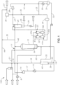
- FIG. 1 depicts a simplified flow diagram of a gas phase olefin polymerization system 100, according to one or more embodiments.
- the gas phase olefin polymerization system 100 can include a polymer production loop 11 and a polymer recovery loop 12. Connected in series within the polymer production loop 11 can be a fluidized bed reactor 13, a cycle gas compressor 14, and a cycle gas cooler 15.
- the outlet from the reactor 13 can be connected by line 16 to the low pressure side of the compressor 14 and the high pressure side of the compressor 14 can be connected via line 17 to the high temperature side of the cooler 15.
- the low temperature side of the cooler 15 can be connected via line 18 to the inlet of the reactor 13.
- the reactor inlet is generally at the bottom of the reactor below a distributor plate 19.
- a first inlet of a vent column 40 can be connected via line 39 to line 18 and can be configured to introduce a first portion of a reactor overhead from line 18 into the vent column 40.
- a second inlet of the vent column 40 can be in fluid communication with line 32, which can be configured to convey a stripping medium, e.g., condensed liquids from condensed liquids drum 31, into the vent column 40.
- the stripping medium introduced via line 32 into the vent column 40 can contact the reactor overhead, which can be rich in ethylene and, if present, other monomers introduced via line 39 to produce (1) a vent column overhead lean in ethylene and, if present, other monomers and (2) a vent column bottoms that can be rich in ethylene and, if present, other monomers.
- the term “rich” when used in phrases such as “X-rich” or “rich in X” means, with respect to an outgoing stream obtained from a device, that the stream includes material X at a concentration higher than in the feed material fed to the same device from which the stream is derived.
- the term “lean” when used in phrases such as “X-lean” or “lean in X” means, with respect to an outgoing stream obtained from a device, that the stream comprises material X at a concentration lower than in the feed material fed to the same device from which the stream is derived.
- An overhead outlet of the vent column 40 can be in fluid communication via line 44 with an exhaust line 37 that can send the vent column overhead to a flare (not shown).
- a bottoms outlet of the vent column 40 via line 45 can be in fluid communication with line 18 for returning the vent column bottoms rich in ethylene and, if present, other monomers to the reactor 13.
- Fresh ethylene from a pipeline or storage can be supplied via line 20 to be mixed with cooled recycled ethylene and, if present, other monomers in line 18 before being introduced into the reactor 13, generally near the bottom of the reactor 13 below (shown) and/or above (not shown) a distributor plate 19.
- One or more C 3 to C 6 alkanes can also be supplied to the reactor 13 via lines 20 and 18 to assist in heat removal and hydrogen to control the degree of polymerization.
- One or more comonomers, such as propylene and/or C 4 to C 8 alpha-olefins can also be supplied to the reactor 13 via line 20.
- a carrier gas for the polymerization catalyst and for fluidizing the growing polymer particles in the reactor can be mixed with fresh catalyst from storage and supplied to the reactor 13 via line 21.
- the reactor 13 can be operated under conditions to maintain the monomer(s) in the gas phase and effective to polymerize the monomer(s) to produce an ethylene homopolymer or copolymer.
- Typical conditions include a temperature of 70°C to 110°C and a pressure of 1,500 kPa-absolute to 3,000 kPa-absolute, such as 1,700 kPa-absolute to 2,600 kPa-absolute.
- the polymer product contains unreacted monomer(s) as well as other hydrocarbons added to, or produced in, the polymerization process as the product leaves the reactor 13.
- the polymer product can be discharged from the reactor 13 along with a reactor gas.
- reactor gas refers to the gas that leaves the reactor, and typically is a mixture that can include ethylene (e.g., unreacted ethylene gas leaving the reactor) and at least a portion of the carrier gas used to fluidize the catalyst and transport it into the reactor in the first place.
- the carrier gas is preferably nitrogen, though it can be any gas that would not react with the catalyst nor alter the polymerization reaction.
- Carrier gases for gas phase fluidized bed polymerization reactors are well known in the art, and their identity is not the focus of the present disclosure.
- the reactor gas may further include hydrogen (used, e.g., as a chain transfer agent in polymerization) as well as reaction and other process byproducts such as water, ammonia, methane, higher alkanes, carbon dioxide, and/or other compounds of oxygen, carbon, and/or hydrogen.
- Particulate polymer product can be removed intermittently from the reactor 13 typically from a region just above the distributor plate 19 and passed to a product discharge system 22 in FIG. 1 .
- the product discharge system 22 can include first and second pairs of lock hoppers 41(a)/41(b) and 42(a)/42(b), respectively, a monomer stripping vessel or product purge bin 24, and a gas vent line 46 in fluid communication with the reactor 13 and the product purge bin 24.
- the first pair of lock hoppers 41(a) and 41(b) and the second pair of lock hoppers 42(a) and 42(b) can be connected in parallel between the reactor 13 and line 23.
- a first cross-tie 43(a) a can be provided between the upstream lock hoppers 41(a) and 42(a) and a second cross-tie 43(b) can be provided between the downstream lock hoppers 41(b), 42(b).
- the first cross-tie 43(a) can also be referred to as the "W cross-tie” and the second cross-tie 43(b) can also be referred to as the "X cross-tie".
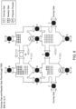
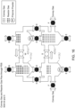
- FIG. 2 depicts a schematic representation of a product discharge system 22 for use in the system of FIG. 1 , according to one or more embodiments.
- the upstream lock hoppers 41(a), 42(a) can be connected by valves B and G to the reactor 13 and can be connected by valves D and H to the downstream lock hopper 41(b), 42(b).
- the downstream lock hoppers 41(b), 42(b), can each be connected by a valve E to line 23 and the product recovery loop 12.
- Each downstream lock hopper 41(b), 42(b) can also be connected by a valve F to a source of conveying gas to facilitate transfer of polymer product from the downstream lock hopper 41(b), 42(b) into line 23.
- a first or W valve can be provided in the first or W cross-tie 43(a) between the upstream lock hoppers 41(a) and 42(a) and a second or X valve can be provided in the second or X cross-tie 43(b) between the downstream lock hoppers 41(b) and 42(b).
- the construction and operation of the product discharge system 22 can be designed not only to provide efficient removal of the solid polymer product but also to allow reduction in effluent pressure without excessive loss of the reactor contents.
- one of the valves B can be opened that connects the reactor 13 with the upstream lock hopper 41(a), with the other valves connected to the hopper 41(a) being closed to isolate it from the remainder of the product discharge system 22.
- the valve B is opened, polymer product and reactor gas flow into the lock hopper 41(a) (as illustrated by the arrow in FIG.
- valve G can be opened to allow the pressure in the lock hopper 41(a) to equilibrate with that of the reactor 13 and thereby facilitate filling of lock hopper 41(a).
- valves B and G can be closed and the valve D connecting lock hoppers 41(a) and 41(b) can be opened to allow the contents of lock hopper 41(a) to be transferred to lock hopper 41(b).
- the hopper 41(b) can be isolated from the remainder of the product discharge system 22 (e.g., with valves X, E, F, and H remaining closed), at least until the hopper 41(b) approaches being filled to a desired level, at which time valve H can also be opened to allow the pressures in lock hoppers 41(a) and 41(b) to equilibrate.
- valves D and H can be closed, and valves E and F can be opened to allow the conveying gas to transport the polymer product from the lock hopper 41(b) to the stripping vessel 24.
- the whole operation can be similarly carried out for lock hoppers 42(a) and 42(b).
- the removal of the polymer product from the reactor 13 through the product discharge system 22 can be effected in sequential removal cycles, where each removal cycle includes the steps of: (1) transferring polymer product and reactor gas from the reactor 13 to (1a) the upstream lock hopper 41(a) of the first pair of lock hoppers 41(a)/41(b) and equilibrating the pressure therebetween or (1b) the upstream lock hopper 42(a) of the second pair of lock hoppers 42(a)/42(b) and equilibrating the pressure therebetween; (2) while performing step (1), transferring polymer product and reactor gas from (2a) the upstream lock hopper 42(a) to the downstream lock hopper 42(b) of the second pair of lock hoppers 42(a)/42(b) and equilibrating the pressure therebetween or (2b) the upstream lock hopper 41(a) to the downstream lock hopper 41(b) of the first pair of lock hoppers 41(a)/41(b) and equilibr
- Steps (1a), (2a), (3a), (4a), and (5a) or steps (1b), (2b), (3b), (4b), and (5b), respectively, can be carried out in sequential order and in alternating removal cycles with respect to one another.
- each lock hopper can be isolated by closed valves from any of the reactor 13, the other lock hoppers, and the product discharge system 22 not necessary for the performance of the respective step.
- Product withdrawal can be initiated when the product inventory in the reactor 13 exceeds a desired value.
- the inventory in the reactor 13 can generally be determined by either the bed level or weight measurements, or from secondary measurements used to infer bed level or bed weight.
- the product discharge system 22 can be initiated to pass the polymer product from the reactor 13 to the product discharge system 22.
- the amount of carrier gas, e.g., nitrogen, within the polymerization system 100 can increase to an undesirable level and active steps to remove excess carrier gas from the polymerization system 100 can be initiated.
- the amount of carrier gas removed as the vent column overhead via line 44 can be sufficient to maintain a desired amount of carrier gas within the polymerization system 100.
- the vent column 40 will have a maximum removal capacity.
- the frequency of step (5) can be reduced such that the reactor gas is passed from one of the downstream lock hoppers to the other downstream lock hopper via the X cross-tie 43(b) only in some, but not all of the removal cycles.
- step (5) When it is determined that an additional quantity of the carrier gas needs to be removed from the polymerization system 100, the frequency of step (5) can be further reduced, up to and including until step (5) ceases, such that the valve X remains closed during all removal cycles, and in none of these cycles is reactor gas passed from downstream lock hopper 41(b) to the downstream lock hopper 42(b). Should it be determined that yet more additional carrier gas needs to be removed from the polymerization system 100, the frequency of step (4) can also be reduced, such that the reactor gas can be passed from one of the upstream lock hoppers to the other upstream lock hopper via the W cross-tie 43(a) only in some, but not all, of the removal cycles.
- step (4) can be further reduced until step (4) ceases, such that the valve W remains closed during all removal cycles, and in none of these removal cycles is reactor gas passed from upstream lock hopper 41(a) to upstream lock hopper 42(a).
- the polymer product and the reactor gas can be transferred from the reactor 13 to (1a) the upstream lock hopper 41(a) of the first pair of lock hoppers 41(a)/41(b) or (1b) the upstream lock hopper 42(a) of the second pair of lock hoppers 42(a)/42(b) for a fixed period of time during each removal cycle.
- the fixed period of time the polymer product can be transferred from the reactor 13 to one of the upstream lock hoppers can be adjusted.
- vent column 40 has reached its maximum removal capacity and the X cross-tie 43(b) and the W cross-tie 43(a) are both closed during all removal cycles, and it is still determined that an even further additional quantity of carrier gas needs to be removed from the polymerization system 100, several further options for removing additional carrier gas can then be used.
- the first further option for removing additional carrier gas can include decreasing the fixed period of time that the polymer product can be transferred from the reactor 13 to one of the upstream lock hoppers. By decreasing the fixed period of time, a greater quantity of reactor gas will be transferred from the reactor 13 into line 23.
- a second further option can include supplying reactor gas from the reactor 13 via the gas vent line 46 to the product purge bin 24. The amount of reactor gas supplied from the reactor 13 via the gas vent line 46 can be increased until a maximum removal capacity of the product purge bin 24 has been reached.
- a third further option includes combining a portion of reactor gas in the gas vent line 46 with the vent column overhead in line 44 (e.g., via line 30), and sending to the flare via line 37.
- the amount of reactor gas that can be sent directly to flare via the combination of lines 46, 30, 44, and 37 can be increased to as large a quantity as needed to reduce the amount of carrier gas in the polymerization system 100 to a desired level.
- reactor gas can be sent to the flare from a line in fluid communication with the polymer production loop and/or a line in fluid communication with the reactor 13 and the flare and/or from any other suitable point within the polymerization system 100.
- a fourth further option that can be used to remove additional carrier gas from the polymerization system 100 can be used before, during, and/or after any stage or step discussed above. There is a set period of time between steps (1a)-(5a) and steps (1b)-(5b) during which no polymer product and reactor gas is transferred from the reactor 13 to the upstream lock hopper 41(a) or 42(a) of either pair of lock hoppers 41(a)/41(b) and 42(a)/42(b). If it is determined additional carrier gas should be removed from the polymerization system 100, the set period of time between steps (1a)-(5a) and steps (1b)-(5b) can be increased.
- Increasing the set period of time between steps (1a)-(5a) and steps (1b)-(5b) during which no polymer product and reactor gas is transferred from the reactor 13 to the upstream lock hopper 41(a) or 42(a) causes additional carrier gas to be removed from the system. More particularly, the fixed period of time the polymer product and the reactor gas are transferred from the reactor 13 to the upstream lock hopper 41(a) or 42(a) decreases as the set period of time between steps (1a)-(5a) and steps (1b)-(5b) increases, which in turn causes the amount of polymer product transferred into the upstream lock hopper 41(a) or 42(b) to decrease, thus increasing the amount of reactor gas that flows into the upstream lock hopper 41(a) or 41(b).
- increasing the set period of time between steps (1a)-(5a) and steps (1b)-(5b) would be implemented only after the vent column 40 reaches its maximum removal capacity.
- determining whether additional carrier gas needs to be removed from the polymerization system 100 can include sensing a pressure within the reactor 13. When the sensed pressure exceeds a pre-determined value, the removal of additional carrier gas can be initiated.
- the pre-determined value can be 3,000 kPa-absolute, 2,800 kPa-absolute, 2,600 kPa-absolute, 2,400 kPa-absolute, 2,200 kPa-absolute, 2,000 kPa-absolute, 1,950 kPa-absolute, 1,900 kPa-absolute, 1,850 kPa-absolute, 1,800 kPa-absolute, 1,700 kPa-absolute, or 1,600 kPa-absolute.
- the particulate polymer collected by the product discharge system 22 can be transferred by a conveying gas, such as nitrogen or a mixture of nitrogen and ethylene, via line 23 to a monomer stripping vessel 24 in the polymer recovery loop 12.
- the polymer product can enter the top of the vessel 24 and, as the polymer product flows downwardly through the vessel 24, the polymer product can be contacted with fresh and/or recycled stripping gas supplied to the bottom of the vessel via line 25.
- the countercurrent contact between the polymer product and the stripping gas can flush out reactor gas entrained in the polymer product and strip and desorb hydrocarbons, including unreacted monomer(s), dissolved in the polymer product.
- the stripping gas may be a gas inert to the polymerization process, such as nitrogen.
- the stripped polymer product can exit the bottom of the vessel 24 and can be fed via line 26 to a finishing section (not shown), whereas the hydrocarbon-containing stripping gas effluent can exit the top of the vessel 24 and can be fed via line 27 to a low pressure side of a recovery compressor 28.
- the high pressure side of the compressor 28 can be connected to a condenser 29 where some of the hydrocarbons contained in the compressed stripping gas effluent can be condensed to produce a condensed liquid.
- the condensed liquid can be recovered in a condensed liquids drum 31 before being introduced into the vent column 40 via line 32. In some embodiments, at least a portion of the condensed liquids in line 32 can be removed from the system 100.
- the gaseous component of the stripping gas effluent remaining after passage through the condenser 29 can be fed via line 33 to a split where a first portion can be removed and, after passage through a surge tank 34, can be recycled to line 23 to assist in conveying the polymer product from the reactor 13 to the stripping vessel 24.
- the remainder of the stripping gas effluent in line 33 can be fed by line 35 to a membrane separation system 36 where entrained hydrocarbons can be removed from the effluent before the remainder of the effluent is fed via line 37 to the flare (not shown).
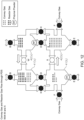
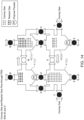
- FIGS. 3 to 19 depict simplified schematic representations of the product delivery system 22 shown in FIG. 2 at different consecutive stages of system operation. More particularly, a preferred sequence of operations of the product discharge system 22 in transferring polymer product from the reactor 13 to the product recovery loop 12 is illustrated in FIGS. 3 to 19 , in which the return valves G are omitted for simplicity.
- valves associated with the first pair of lock hoppers 41 can be referred to as "first" valves, for example, first valve B
- valves associated with the second pair of lock hoppers 42 can be referred to as "second" valves, for example, second valve B.
- FIG. 3 to 19 show polymer product (or polymer powder), reactor gas, and convey gas illustrated as discrete units (e.g., circles depicting a unit of each type of gas; and larger circles depicting the polymer product).
- Valves are shown as open with unfilled circles; and closed with filled or solid circles (for example, in FIG. 3 , first valve B is open; second valve B is closed; valves W and X are closed, etc.).
- FIG. 3 shows an initial position of the product discharge system 22 in which the following conditions apply:
- FIG. 4 shows the configuration of the product discharge system 22 at the next stage of operation after the initial position shown in FIG. 3 , in which the positions of the various valves and the material flows are as follows:
- FIG. 5 shows the configuration of the product discharge system 22 at the next stage of operation after the position shown in FIG. 4 , in which the positions of the various valves and the material flows are as follows:
- FIG. 6 shows the configuration of the product discharge system 22 at the next stage of operation after the position shown in FIG. 5 , in which the cross-tie W is now opened while all the remaining valves (including the cross-tie X) are closed.
- the lock hopper 41(a) is at this stage at a higher pressure than the lock hopper 42(a)
- half of the gaseous contents of the lock hopper 41(a) are transferred via cross-tie W to lock hopper 42(a) to equilibrate the pressures.
- the lock hopper 41(a) then contains 18 units of reactor gas and lock hopper 42(a) contains 36 units of reactor gas and 18 units of conveying gas.
- FIG. 7 shows the configuration of the product discharge system 22 at the next stage of operation after the position shown in FIG. 6 , in which the positions of the various valves and the material flows are as follows:
- FIG. 8 shows the configuration of the product discharge system 22 at the next stage of operation after the position shown in FIG. 7 , in which the cross-tie W is again opened while all the remaining valves (including the cross-tie X) are closed.
- the lock hopper 42(a) is now at a higher pressure than the lock hopper 41(a)
- half of the gaseous contents of the lock hopper 42(a) are transferred via cross-tie W to lock hopper 41(a) to equilibrate the pressures.
- the lock hopper 41(a) then contains 27 units of reactor gas and lock hopper 42(a) contains 18 units of reactor gas.
- FIG. 9 shows the configuration of the product discharge system 22 at the next stage of operation after the position shown in FIG. 8 , in which the positions of the various valves and the material flows are as follows:
- FIG. 10 shows the configuration of the product discharge system 22 at the next stage of operation after the position shown in FIG. 9 , in which the cross-tie W is again opened while all the remaining valves (including the cross-tie X) are closed.
- the lock hopper 41(a) is now at a higher pressure than the lock hopper 42(a)
- half of the gaseous contents of the lock hopper 41(a) are transferred via cross-tie W to lock hopper 42(a) to equilibrate the pressures.
- the lock hopper 41(a) then contains 18 units of reactor gas and lock hopper 42(a) contains 27 units of reactor gas and 18 units of conveying gas.
- FIG. 11 shows the configuration of the product discharge system 22 at the next stage of operation after the position shown in FIG. 10 , in which the positions of the various valves and the material flows are as follows:
- FIG. 12 shows the configuration of the product discharge system 22 at the next stage of operation after the position shown in FIG. 11 , in which both cross-ties W and X are opened while all the remaining valves are closed.
- the lock hopper 42(a) is at a higher pressure than the lock hopper 41(a)
- half of the gaseous contents of the lock hopper 42(a) are transferred via cross-tie W to lock hopper 41(a) to equilibrate the pressures.
- the lock hopper 41(a) then contains 27 units of reactor gas and 18 units of conveying gas, while lock hopper 42(a) contains 18 units of reactor gas.
- lock hopper 41(b) since the lock hopper 41(b) is at a higher pressure than the lock hopper 42(b), half of the gaseous contents of the lock hopper 41(b) are transferred via cross-tie X to lock hopper 42(b) to equilibrate the pressures.
- the lock hopper 41(b) then contains 5 units of reactor gas and 9 units of conveying gas, while lock hopper 42(b) contains 4 units of reactor gas and 45 units of conveying gas.
- FIG. 13 shows the configuration of the product discharge system 22 at the next stage of operation after the position shown in FIG. 12 , in which the positions of the various valves and the material flows are as follows:
- FIG. 14 shows the configuration of the product discharge system 22 at the next stage of operation after the position shown in FIG. 13 , in which both cross-ties W and X are again opened while all the remaining valves are closed.
- the lock hopper 41(a) is at a higher pressure than the lock hopper 42(a)
- half of the gaseous contents of the lock hopper 41(a) are transferred via cross-tie W to lock hopper 42(a) to equilibrate the pressures.
- the lock hopper 41(a) then contains 18 units of reactor, while lock hopper 42(a) contains 29 units of reactor gas and 22 units of conveying gas.
- lock hopper 42(b) since the lock hopper 42(b) is at a higher pressure than the lock hopper 41(b), half of the gaseous contents of the lock hopper 42(b) are transferred via cross-tie X to lock hopper 41(b) to equilibrate the pressures.
- the lock hopper 41(b) then contains 5 units of reactor gas and 47 units of conveying gas, while lock hopper 42(b) contains 6 units of reactor gas and 12 units of conveying gas.
- FIG. 15 shows the configuration of the product discharge system 22 at the next stage of operation after the position shown in FIG. 14 , in which the positions of the various valves and the material flows are as follows:
- FIG. 16 shows the configuration of the product discharge system 22 at the next stage of operation after the position shown in FIG. 15 , in which both cross-ties W and X are again opened while all the remaining valves are closed.
- the lock hopper 42(a) is at a higher pressure than the lock hopper 41(a)
- half of the gaseous contents of the lock hopper 42(a) are transferred via cross-tie W to lock hopper 41(a) to equilibrate the pressures.
- the lock hopper 41(a) then contains 29 units of reactor gas and 23 units of conveying gas, while lock hopper 42(a) contains 18 units of reactor gas.
- lock hopper 41(b) since the lock hopper 41(b) is at a higher pressure than the lock hopper 42(b), half of the gaseous contents of the lock hopper 41(b) are transferred via cross-tie X to lock hopper 42(b) to equilibrate the pressures.
- the lock hopper 41(b) then contains 6 units of reactor gas and 12 units of conveying gas, while lock hopper 42(b) contains 6 units of reactor gas and 48 units of conveying gas.
- FIG. 17 shows the configuration of the product discharge system 22 at the next stage of operation after the position shown in FIG. 16 , in which the positions of the various valves and the material flows are as follows:
- FIG. 18 shows the configuration of the product discharge system 22 at the next stage of operation after the position shown in FIG. 17 , in which both cross-ties W and X are again opened while all the remaining valves are closed.
- the lock hopper 41(a) is at a higher pressure than the lock hopper 42(a)
- half of the gaseous contents of the lock hopper 41(a) are transferred via cross-tie W to lock hopper 42(a) to equilibrate the pressures.
- the lock hopper 41(a) then contains 18 units of reactor, while lock hopper 42(a) contains 30 units of reactor gas and 24 units of conveying gas.
- lock hopper 42(b) since the lock hopper 42(b) is at a higher pressure than the lock hopper 41(b), half of the gaseous contents of the lock hopper 42(b) are transferred via cross-tie X to lock hopper 41(b) to equilibrate the pressures.
- the lock hopper 41(b) then contains 6 units of reactor gas and 48 units of conveying gas, while lock hopper 42(b) contains 6 units of reactor gas and 12 units of conveying gas.
- FIG. 19 shows the configuration of the product discharge system 22 at the next stage of operation after the position shown in FIG. 18 , in which the positions of the various valves and the material flows are as follows:
- FIGS. 3 to 5 it will be seen that, when a charge of polymer product is transferred from the reactor 13 to one of the upstream lock hoppers 41(a), 42(a) without previous opening of either of the W and X cross-ties, 18 units of reactor gas and 18 units of conveying gas flow back into the reactor through valve G.
- FIG. 5 also shows that the simultaneous transfer of polymer product from the corresponding downstream lock hopper 41(b), 42(b) to the product recovery loop 12 is accompanied by the flow of 18 units of reactor gas and 18 units of conveying gas to the product recovery loop 12.
- FIG. 11 shows that the simultaneous transfer of polymer product from the corresponding downstream lock hopper 41(b), 42(b) to the product recovery loop 12 - when the system has reach equilibrium - is accompanied by the flow of 9 units of reactor gas and 18 units of conveying gas to the product recovery loop 12.
- FIG. 19 shows that, again after the system has reached equilibrium, when a charge of polymer product is transferred from the reactor 13 to one of the upstream lock hoppers 41(a), 42(a) after previous opening of both of the W and X cross-ties, 30 units of reactor gas and 24 units of conveying gas flow back into the reactor through valve G.
- FIG. 19 also shows that the simultaneous transfer of polymer product from the corresponding downstream lock hopper 41(b), 42(b) to the product recovery loop 12 is accompanied by the flow of 6 units of reactor gas and 12 units of conveying gas to the product recovery loop 12.
- Gas phase polyethylene reactors of the type shown in FIGS. 1 and 2 have historically controlled pressure by increasing or decreasing the W valve utilization percentage of the product discharge system.
- the W cross-tie is opened after a charge of polymer product is delivered to one of the upstream lock hoppers to allow equalization in pressure with the other upstream lock hopper, thereby reducing net gas loss from the reactor during the next delivery of polymer product.
- Increasing the percent of deliveries during which the W valve is used decreases gas flow from the reactor.
- reactor pressure is high, the W valve utilization can decrease, increasing the rate of material removal from the reactor.
- Operation of the X cross-tie can be scheduled by a controller that treats the analog action of the X cross-tie as a digital control valve by sensing the pressure in the reactor; and reducing the optional operation of the X cross-tie during removal cycles when the sensed reactor pressure exceeds a predetermined value, such as when the sensed reactor pressure exceeds 1,800 kPa-absolute, or exceeds 2,000 kPa-absolute.
- the controller can reduce X cross-tie use by scheduling product discharge cycles to occur without the X cross-tie step. If the reactor pressure controller is calling for direct venting of reactor gas, the scheduler will call for more cycles without the X cross-tie, resulting in each cycle removing more reactor gas.
- the reduction of nitrogen from the product discharge system due to the decrease or stopping of the X cross-tie use can hasten the pressure change and reduce or even prevent the need for direct reactor venting. This results in a net reduction of gas venting from the reactor.
- Operation of the W cross-tie can be scheduled by a controller that treats the analog action of the W cross-tie as a digital control valve by sensing the pressure in the reactor and reducing the optional operation of the W cross-tie during removal cycles when the X cross-tie has ceased being opened during any removal cycle and the sensed reactor pressure exceeds a predetermined value, such as when the sensed reactor pressure exceeds 1,800 kPa-absolute, or exceeds 2,000 kPa-absolute.
- the controller can reduce W cross-tie use by scheduling product discharge cycles to occur without the W cross-tie step.
- the scheduler will call for more cycles without the W cross-tie, resulting in each cycle removing more reactor gas.
- the reduction of nitrogen from the product discharge system due to the decrease or stopping of the W cross-tie use can hasten the pressure change and reduce or even prevent the need for direct reactor venting. This results in a net reduction of gas venting from the reactor.
- additional carrier gas can be removed from the polymerization system by: (i) decreasing the fixed period of time the polymer product and the reactor gas are transferred from the reactor 13 to (1a) the upstream lock hopper 41(a) of the first pair of lock hoppers 41(a)/41(b) or (1b) the upstream lock hopper 42(a) of the second pair of lock hoppers 42(a)/42(b); (ii) supplying reactor gas from the reactor 13 via the gas vent line 46 to the product purge bin 24 and then (iii) increasing the amount of the reactor gas supplied from the reactor 13 via the gas vent line 46 to the product purge bin 24 until a maximum removal capacity of the product purge bin 24 is reached; and/or (iv) supplying additional reactor gas from the reactor via the combination of lines 46, 30, 44, and 37 directly to the flare until a sufficient amount of carrier gas is removed from the gas phase polymerization system 100.
- options (i), (ii), and (iii) can preferably be employed before option (iv). In some embodiments, option (i) can be carried out first, followed by option (ii), then option (iii), and then option (iv).
Landscapes
- Chemical & Material Sciences (AREA)
- Organic Chemistry (AREA)
- Chemical Kinetics & Catalysis (AREA)
- Engineering & Computer Science (AREA)
- Combustion & Propulsion (AREA)
- Health & Medical Sciences (AREA)
- Medicinal Chemistry (AREA)
- Polymers & Plastics (AREA)
- Polymerisation Methods In General (AREA)
Claims (15)
- Verfahren zum Entlüften eines Gasphasenpolymerisationssystems (100), wobei bei dem Verfahren:(a) ein Gasphasenpolymerisationssystem (100) bereitgestellt wird, das einen Reaktor (13), einen Reaktor-Rückführungskreislauf in Fließverbindung mit einem Auslass und einem Einlass des Reaktors (13), eine Verbrennungsfackel in Fließverbindung mit dem Reaktor-Rückführungskreislauf, eine Entlüftungssäule (40) in Fließverbindung mit dem Reaktor-Rückführungskreislauf und der Verbrennungsfackel, ein Produktausgabesystem (22) mit ersten und zweiten Paaren von Sperrtrichtern (41a, 41b, 42a, 42b) und mit einem Produktausgabebehälter (24), und eine Gasentlüftungsleitung (46) aufweist, die in Fließverbindung mit dem Reaktor (13) und dem Produktausgabebehälter (24) steht, wobei jedes Paar von Sperrtrichtern einen stromaufwärts liegenden Sperrtrichter (41a, 42a), der durch Ventile (B) und (G) mit dem Reaktor (13) verbunden ist, und einen stromabwärts liegenden Sperrtrichter (41b, 42b) aufweist, der durch Ventile (D) und (H) mit dem stromaufwärts liegenden Sperrtrichter (41a, 42a) verbunden ist und der durch ein Ventil (E) mit dem Produktausgabebehälter (24) verbunden ist, wobei eine erste Querverbindung (W) zwischen den stromaufwärts liegenden Sperrtrichtern (41a, 42a) der ersten und zweiten Paare von Sperrtrichtern und eine zweite Querverbindung (X) zwischen den stromabwärts liegenden Sperrtrichtern (41b, 42b) der ersten und zweiten Paare von Sperrtrichtern vorgesehen ist und wobei die ersten und zweiten Querverbindungen (W) und (X) jeweils ein Ventil umfassen, das dazu ausgestaltet ist, jeweils Fließverbindung zwischen den stromaufwärts liegenden Sperrtrichtern (41a, 42a) und den stromabwärts liegenden Sperrtrichtern (41b, 42b) selektiv zuzulassen und selektiv zu unterbinden,(b) Olefin-Monomer, ein Trägergas und teilchenförmiger Katalysator dem Reaktor (13) unter Bedingungen zugeführt werden, die bewirken, dass der teilchenförmige Katalysator in einem fluidisierten Zustand bleibt und dass Olefin-Monomer in Gegenwart des teilchenförmigen Katalysators polymerisiert, um ein Polymerprodukt zu erzeugen,(c) ein Reaktor-Überkopfprodukt, das Reaktorgas aus dem Auslass des Reaktors (13) enthält, dem Reaktor-Rückführungskreislauf zugeführt wird, wobei das Reaktorgas unreagiertes Olefin-Monomer und Trägergas enthält,(d) ein erster Teil des Reaktor-Überkopfproduktes in den Reaktor-Rückführungskreislauf der Entlüftungssäule (40) zugeführt wird,(e) der erste Teil des Reaktor-Überkopfproduktes innerhalb der Entlüftungssäule (40) mit einem Abscheidemedium in Kontakt gebracht wird, um wenigstens einen Teil der OlefinMonomere zu entfernen, um ein Entlüftungssäulen-Überkopfprodukt zu erzeugen, das reich an Trägergas und arm an Olefin-Monomer ist, und ein Entlüftungssäulen-Bodenprodukt zu erzeugen, das reich an Olefin-Monomer und arm an Trägergas ist,(f) das Entlüftungssäulen-Überkopfprodukt der Verbrennungsfackel zugeführt wird,(g) ein zweiter Teil des Reaktor-Überkopfproduktes in den Reaktor-Rückführungskreislauf und das Entlüftungssäulen-Bodenprodukt dem Reaktor (13) zugeführt werden,(h) das Polymerprodukt und eine zusätzliche Menge von Reaktorgas aus dem Reaktor (13) durch die ersten und zweiten Paare von Sperrtrichtern (41a, 42b, 42a, 42b) in Entnahmezyklen entnommen werden,
wobei jeder Entnahmezyklus (h) die Schritte beinhaltet:(1) Übertragen von Polymerprodukt und Reaktorgas aus dem Reaktor (13) zum (1a) stromaufwärts liegenden Sperrtrichter (41a) des ersten Paars von Sperrtrichtern und ins Gleichgewichtbringen des Drucks dazwischen oder zum (1b) stromaufwärts liegenden Sperrtrichter (42a) des zweiten Paars von Sperrtrichtern uns ins Gleichgewichtbringen des Druckes dazwischen,(2) während der Ausführung von Schritt (1) Übertragen von Polymerprodukt und Reaktorgas von (2a) dem stromaufwärts liegenden Sperrtrichter (42a) zum stromabwärts liegenden Sperrtrichter (42b) des zweiten Paars von Sperrtrichtern und ins Gleichgewichtbringen des Drucks dazwischen oder (2b) von dem stromaufwärts liegenden Sperrtrichter (41a) zu dem stromabwärts liegenden Sperrtrichter (41b) des ersten Paars von Sperrtrichtern und ins Gleichgewichtbringen des Druckes dazwischen,(3) während der Durchführung der Schritte (1) und (2) Übertragen von Polymerprodukt unter Verwendung eines Fördergases von (3a) dem stromabwärts liegenden Sperrtrichter (41b) des ersten Paars von Sperrtrichtern zum Produktausgabebehälter (24) oder von (3b) dem stromabwärts liegenden Sperrtrichter (42b) des zweiten Paars von Sperrtrichtern zum Produktausgabebehälter (24),(4) nach Durchführung der Schritte (1), (2) und (3) Leiten von Reaktorgas von (4a) dem stromaufwärts liegenden Sperrtrichter (41a) des ersten Paars von Sperrtrichtern zum stromaufwärts liegenden Sperrtrichter (42a) des zweiten Paars von Sperrtrichtern über die erste Querverbindung (W), um den Druck dazwischen ins Gleichgewicht zu bringen, oder von (4b) dem stromaufwärts liegenden Sperrtrichter (42a) des zweiten Paars von Sperrtrichtern zum stromaufwärts liegenden Sperrtrichter (41a) des ersten Paars von Sperrtrichtern über die erste Querverbindung (W), um den Druck dazwischen ins Gleichgewicht zu bringen, und wobei weiterhin einige oder alle Entnahmezyklen (h) den weiteren Schritt aufweisen:(5) nach Durchführung der Schritte (1), (2) und (3) Leiten von Reaktorgas von (5a) dem stromabwärts liegenden Sperrtrichter (41b) des ersten Paars von Sperrtrichtern zum stromabwärts liegenden Sperrtrichter (42b) des zweiten Paars von Sperrtrichtern über die zweite Querverbindung (X), um den Druck dazwischen ins Gleichgewicht zu bringen, oder von (5b) dem stromabwärts liegenden Sperrtrichter (42b) des zweiten Paars von Sperrtrichtern zum stromabwärts liegenden Sperrtrichter (41b) des ersten Paars von Sperrtrichtern über die zweite Querverbindung (X), um den Druck dazwischen ins Gleichgewicht zu bringen,wobei die Schritte (1a), (2a), (3a), (4a) und (5a) oder die Schritte (1b), (2b), (3b), (4b) und (5b) jeweils in sequenzieller Folge und in alternierenden Entnahmezyklen (h) in Bezug zueinander ausgeführt werden,(i) eine zusätzliche Menge von Trägergas bestimmt wird, das aus dem Gasphasenpolymerisationssystem (100) entfernt werden muss,(j) eine Menge des ersten Teils des Reaktor-Überkopfproduktes im Reaktor-Rückführungskreislauf, die der Entlüftungssäule (40) zugeführt wird, vergrößert wird, bis eine maximale Entnahmekapazität der Entlüftungssäule erreicht ist, und(k) die Frequenz von Schritt (5) reduziert wird, so dass nach Durchführen der Schritte (1), (2) und (3) das Reaktorgas von einem der stromabwärts liegenden Sperrtrichter (41b oder 42b) zum anderen stromabwärts liegenden Sperrtrichter (42b oder 41b) über die zweite Querverbindung (X) in einigen, aber nicht in allen der Entnahmezyklen (h) geleitet wird. - Prozess nach Anspruch 1, mit den weiteren Schritten:(l) Bestimmen von zusätzlichem Trägergas, das aus dem Gasphasenpolymerisationssystem (100) entfernt werden muss, und(m) Beenden von Schritt (5), so dass das Ventil der zweiten Querverbindung (X) Fließverbindung zwischen den stromabwärts liegenden Sperrtrichtern (41b, 42b) während aller Entnahmezyklen (h) verhindert.
- Verfahren nach Anspruch 2, mit den weiteren Schritten:(n) Bestimmen von zusätzlichem Trägergas, das aus dem Gasphasenpolymerisationssystem (100) entfernt werden muss, und(o) Reduzieren der Frequenz von Schritt (4), so dass nach Durchführen von den Schritten (1), (2) und (3) das Reaktorgas von einem der stromaufwärts liegenden Sperrtrichter (41a oder 42a) zum anderen stromaufwärts liegenden Sperrtrichter (42a oder 41a) über die erste Querverbindung (W) in einigen, aber nicht allen Entnahmezyklen (h) geleitet wird.
- Verfahren nach Anspruch 3, mit den weiteren Schritten:(p) Bestimmen von zusätzlichem Trägergas, das aus dem Gasphasenpolymerisationssystem (100) entfernt werden muss, und(q) Beenden von Schritt (4), so dass das Ventil der ersten Querverbindung (W) Fließverbindung zwischen den stromaufwärts liegenden Sperrtrichtern (41a, 42a) während aller Entnahmezyklen (h) verhindert.
- Verfahren nach Anspruch 4, wobei das Polymerprodukt und das Reaktorgas von dem Reaktor (13) zum (1a) stromaufwärts liegenden Sperrtrichter (41a) des ersten Paars von Sperrtrichtern oder zum (1b) stromaufwärts liegenden Sperrtrichter (42a) des zweiten Paars von Sperrtrichtern für eine festgelegte Zeitperiode während jedes Entnahmezyklus (h) übertragen wird, wobei das Verfahren die weiteren Schritte beinhaltet:(r) Bestimmen von zusätzlichem Trägergas, das aus dem Gasphasenpolymerisationssystem (100) entfernt werden muss, und mit einem oder mehreren der folgenden Schritte:(s) Verkürzen der festgelegten Zeitperiode,(u) Zuführen von Reaktorgas aus dem Reaktor (13) über die Gasentlüftungsleitung (46) zum Produktausgabebehälter (24),(w) Erhöhen des Anteils des aus dem Reaktor (13) über die Gasentlüftungsleitung (46) dem Produktausgabebehälter (24) zugeführten Menge von Reaktorgas, bis eine maximale Entnahmekapazität des Produktausgabebehälters (24) erreicht ist,(y) Zuführen von Reaktorgas von dem Reaktor (13) zur Verbrennungsfackel, bis eine ausreichende Menge von Trägergas aus dem Gasphasenpolymerisationssystem (100) entfernt ist.
- Verfahren nach einem der vorhergehenden Ansprüche, wobei es eine festgesetzte Zeitperiode zwischen den Schritten (1a)-(5a) und den Schritten (1b)-(5b) gibt, während der kein Polymerprodukt und kein Reaktorgas von dem Reaktor (13) zu dem stromaufwärts liegenden Sperrtrichter (41a oder 42a) von irgendeinem Paar der Sperrtrichter gibt, wobei das Verfahren die weiteren Schritte beinhaltet:(z) Bestimmen von zusätzlichem Trägergas, das aus dem Gasphasenpolymerisationssystem (100) entfernt werden muss, und(aa) Vergrößern der festgesetzten Zeitperiode zwischen den Schritten (1a)-(5a) und den Schritten (1b)-(5b), während der kein Polymerprodukt und kein Reaktorgas aus dem Reaktor (13) in den stromaufwärts liegenden Sperrtrichter (41a oder 42a) von irgendeinem Paar der Sperrtrichter übertragen wird.
- Verfahren nach einem der vorhergehenden Ansprüche, wobei das Trägergas und das Fördergas jeweils molekularen Stickstoff enthalten, wobei optional das Fördergas ein Gemisch aus molekularem Stickstoff und Ethylen aufweist.
- Verfahren nach einem der vorhergehenden Ansprüche, wobei das Olefin-Monomer Ethylen enthält, wobei optional das Olefin-Monomer Ethylen und wenigstens eines von C3 bis C8 Alpha-Olefin enthält.
- Prozess nach einem der vorhergehenden Ansprüche, wobei die Polymerisation von Olefin-Monomer in Schritt (b) unter Bedingungen durchgeführt wird, so dass das Olefin-Monomer in der Gasphase ist.
- Verfahren nach einem der vorhergehenden Ansprüche, wobei die Polymerisation von Olefin-Monomer in Schritt (b) unter Bedingungen einschließlich einer Temperatur von 70°C bis 110°C und einem Druck von 1.500 kPa absolut bis 3.000 kPa absolut durchgeführt wird.
- Verfahren nach einem der vorhergehenden Ansprüche, wobei das Bestimmen von zusätzlichem Trägergas, das aus dem Gasphasenpolymerisationssystem (100) entfernt werden muss, beinhaltet, den Druck im Reaktor (13) zu messen und, wenn der Druck einen vorgegebenen Wert übersteigt, zusätzliches Trägergas aus dem Gasphasenpolymerisationssystem (100) zu entfernen.
- Verfahren nach Anspruch 11, wobei der vorgegebene Wert 2.000 kPa absolut ist.
- Verfahren nach Anspruch 11, wobei der vorgegebene Wert 1.800 kPa absolut ist.
- Verfahren nach einem der vorhergehenden Ansprüche, wobei das Abscheidemedium, das mit dem ersten Teil des ReaktorÜberkopfprodukts innerhalb der Entlüftungssäule (40) in Kontakt gebracht wird, kondensierte Kohlenwasserstoffe enthält, die von dem Polymerprodukt im Produktausgabebehälter (24) abgetrennt sind.
- Verfahren nach einem der vorhergehenden Ansprüche, wobei während der Schritte (1), (2), (3), (4) und (5) jeder Sperrtrichter (41a, 41b, 42a, 42b) durch geschlossene Ventile gegenüber allen von dem Reaktor (13), den anderen Sperrtrichtern und dem Produktausgabebehälter (24), die für die Durchführung des jeweiligen Schrittes nicht notwendig sind, isoliert ist.
Applications Claiming Priority (2)
| Application Number | Priority Date | Filing Date | Title |
|---|---|---|---|
| US202163157392P | 2021-03-05 | 2021-03-05 | |
| PCT/US2022/070841 WO2022187791A1 (en) | 2021-03-05 | 2022-02-25 | Processes for venting olefin polymerization systems |
Publications (2)
| Publication Number | Publication Date |
|---|---|
| EP4301503A1 EP4301503A1 (de) | 2024-01-10 |
| EP4301503B1 true EP4301503B1 (de) | 2024-12-18 |
Family
ID=81321682
Family Applications (1)
| Application Number | Title | Priority Date | Filing Date |
|---|---|---|---|
| EP22714971.3A Active EP4301503B1 (de) | 2021-03-05 | 2022-02-25 | Verfahren zur entlüftung von olefinpolymerisationssystemen |
Country Status (4)
| Country | Link |
|---|---|
| US (1) | US20240043581A1 (de) |
| EP (1) | EP4301503B1 (de) |
| CN (1) | CN117083120A (de) |
| WO (1) | WO2022187791A1 (de) |
Families Citing this family (3)
| Publication number | Priority date | Publication date | Assignee | Title |
|---|---|---|---|---|
| WO2025136637A1 (en) | 2023-12-20 | 2025-06-26 | ExxonMobil Technology and Engineering Company | Recovery method for polyolefin synthesis |
| WO2025136636A1 (en) | 2023-12-20 | 2025-06-26 | ExxonMobil Technology and Engineering Company | Recovery system for polyolefin synthesis |
| WO2025136612A1 (en) | 2023-12-20 | 2025-06-26 | ExxonMobil Technology and Engineering Company | Purification bed systems and methods of use |
Family Cites Families (22)
| Publication number | Priority date | Publication date | Assignee | Title |
|---|---|---|---|---|
| US4003712A (en) | 1970-07-29 | 1977-01-18 | Union Carbide Corporation | Fluidized bed reactor |
| US4086409A (en) | 1973-12-20 | 1978-04-25 | Union Carbide Corporation | Ethylene polymerization with siloxane modified catalyst |
| US4011382A (en) | 1975-03-10 | 1977-03-08 | Union Carbide Corporation | Preparation of low and medium density ethylene polymer in fluid bed reactor |
| US4303771A (en) | 1978-12-14 | 1981-12-01 | Union Carbide Corporation | Process for the preparation of high density ethylene polymers in fluid bed reactor |
| US4621952A (en) | 1981-07-28 | 1986-11-11 | Union Carbide Corporation | Fluidized bed discharge process |
| US4349648A (en) | 1981-07-31 | 1982-09-14 | Union Carbide Corporation | Catalyst composition for copolymerizing ethylene |
| DZ520A1 (fr) | 1982-03-24 | 2004-09-13 | Union Carbide Corp | Procédé perfectionné pour accroitre le rendement espace temps d'une réaction de polymérisation exothermique en lit fluidisé. |
| FR2666338B1 (fr) | 1990-08-31 | 1994-04-08 | Bp Chemicals Snc | Procede regule de polymerisation d'olefine en phase gazeuse effectue a l'aide d'un catalyseur a base d'oxyde de chrome. |
| US5352749A (en) | 1992-03-19 | 1994-10-04 | Exxon Chemical Patents, Inc. | Process for polymerizing monomers in fluidized beds |
| DE4217171A1 (de) | 1992-05-23 | 1993-11-25 | Basf Ag | Kontinuierliches Gasphasenwirbelschichtverfahren zur Herstellung von Ethylenhomopolymerisaten und -copolymerisaten |
| US6063877A (en) | 1997-07-31 | 2000-05-16 | Union Carbide Chemicals & Plastics Technology Corporation | Control of gas phase polymerization reactions |
| US6689845B1 (en) | 1998-07-08 | 2004-02-10 | Basell Poliolefine Italia S.P.A. | Process and apparatus for the gas-phase polymerization |
| US6255411B1 (en) * | 1999-04-07 | 2001-07-03 | Union Carbide Chemicals & Plastics Technology Corporation | Reactor product discharge system |
| DE10139477A1 (de) | 2001-08-10 | 2003-02-20 | Basell Polyolefine Gmbh | Optimierung der Wärmeabfuhr im Gasphasenwirbelschichtverfahren |
| US20050137364A1 (en) | 2003-12-23 | 2005-06-23 | Univation Technologies, Llc | Condensing mode operation of gas-phase polymerization reactor |
| MX2009003789A (es) * | 2006-10-10 | 2009-06-19 | Univation Tech Llc | Sistemas de descarga y metodos de usarlos. |
| KR20090086549A (ko) * | 2006-10-10 | 2009-08-13 | 유니베이션 테크놀로지즈, 엘엘씨 | 용기로부터 고체를 제거하기 위한 배출 시스템 |
| BRPI0820663A2 (pt) | 2007-11-27 | 2015-06-16 | Univation Tech Llc | Alimentação de hidrocarbonetos integrada com separador e método de usar o mesmo |
| US20090214395A1 (en) | 2008-02-27 | 2009-08-27 | The Dow Chemical Company | Raw Material Efficiency Method and Process |
| US9328177B2 (en) | 2012-12-28 | 2016-05-03 | Exxonmobil Research And Engineering Company | Methods for processing and interpreting signals from static and acoustic probes in fluidized bed reactor systems |
| EP3746204A4 (de) * | 2018-01-31 | 2021-09-15 | W. R. Grace & Co.-Conn | Ferndruckmessung für polymerreaktorsteuerung |
| US11492422B2 (en) * | 2020-11-19 | 2022-11-08 | Exxonmobil Chemical Patents Inc. | Olefin polymerization processes |
-
2022
- 2022-02-25 EP EP22714971.3A patent/EP4301503B1/de active Active
- 2022-02-25 US US18/264,515 patent/US20240043581A1/en active Pending
- 2022-02-25 CN CN202280018144.2A patent/CN117083120A/zh active Pending
- 2022-02-25 WO PCT/US2022/070841 patent/WO2022187791A1/en not_active Ceased
Also Published As
| Publication number | Publication date |
|---|---|
| EP4301503A1 (de) | 2024-01-10 |
| CN117083120A (zh) | 2023-11-17 |
| WO2022187791A1 (en) | 2022-09-09 |
| US20240043581A1 (en) | 2024-02-08 |
Similar Documents
| Publication | Publication Date | Title |
|---|---|---|
| EP4301503B1 (de) | Verfahren zur entlüftung von olefinpolymerisationssystemen | |
| US11492422B2 (en) | Olefin polymerization processes | |
| KR100893097B1 (ko) | 올레핀 중합체를 제조하기 위한 방법 및 장치 | |
| US7531606B2 (en) | Method for operating a gas phase polymerization reactor | |
| CN104918967B (zh) | 用于处理通过气相聚合所获得的聚烯烃颗粒的方法 | |
| US20250025822A1 (en) | Reactor vent control to avoid vent column breakthrough | |
| EP1362069B1 (de) | Prozess durchgeführt im kondensationsmodus im gasphasenwirbelschichtverfahren, mit flüssigphasenanreicherung und gasphasenwirbelschicht-injektion | |
| CN105209502A (zh) | 用于烯烃聚合的多级方法 | |
| CN101378832B (zh) | 转换环流反应器的方法 | |
| US7582710B2 (en) | Degassing process | |
| CN101501079A (zh) | 聚烯烃精制法 | |
| US20250367594A1 (en) | Product Purge Bin Mid-Vent As Primary Purge Gas Vent Control | |
| CN106029705A (zh) | 包括脱气段的聚合方法和聚合单元 | |
| US6407184B1 (en) | Method of multistage gas phase polymerization, apparatus therefor and device for reducing entrainment of subcomponents in polymer powder in apparatus for multistage gas phase polymerization | |
| JP5179466B2 (ja) | マルチプルループ反応装置のフラッシング | |
| US11117980B2 (en) | Polymerization processes | |
| US8017702B2 (en) | Polymerisation process | |
| CN110291115B (zh) | 用于烯烃单体的气相聚合的改进的方法和系统 | |
| EP4302868B1 (de) | Polyolefinherstellungsvorrichtung und polyolefinherstellungsverfahren | |
| CN114075309A (zh) | 一种调控聚烯烃性能的方法及系统 | |
| JP3877400B2 (ja) | ポリオレフィンの製造方法および製造装置 | |
| JP3373673B2 (ja) | 粉粒体移送方法及び装置 | |
| CN1296019A (zh) | 发粘聚合物生产的过渡策略 | |
| US20100240843A1 (en) | Purging devices for use in polymerization processes |
Legal Events
| Date | Code | Title | Description |
|---|---|---|---|
| STAA | Information on the status of an ep patent application or granted ep patent |
Free format text: STATUS: UNKNOWN |
|
| STAA | Information on the status of an ep patent application or granted ep patent |
Free format text: STATUS: THE INTERNATIONAL PUBLICATION HAS BEEN MADE |
|
| PUAI | Public reference made under article 153(3) epc to a published international application that has entered the european phase |
Free format text: ORIGINAL CODE: 0009012 |
|
| STAA | Information on the status of an ep patent application or granted ep patent |
Free format text: STATUS: REQUEST FOR EXAMINATION WAS MADE |
|
| 17P | Request for examination filed |
Effective date: 20230907 |
|
| AK | Designated contracting states |
Kind code of ref document: A1 Designated state(s): AL AT BE BG CH CY CZ DE DK EE ES FI FR GB GR HR HU IE IS IT LI LT LU LV MC MK MT NL NO PL PT RO RS SE SI SK SM TR |
|
| DAV | Request for validation of the european patent (deleted) | ||
| DAX | Request for extension of the european patent (deleted) | ||
| GRAP | Despatch of communication of intention to grant a patent |
Free format text: ORIGINAL CODE: EPIDOSNIGR1 |
|
| STAA | Information on the status of an ep patent application or granted ep patent |
Free format text: STATUS: GRANT OF PATENT IS INTENDED |
|
| INTG | Intention to grant announced |
Effective date: 20240801 |
|
| P01 | Opt-out of the competence of the unified patent court (upc) registered |
Free format text: CASE NUMBER: APP_50625/2024 Effective date: 20240906 |
|
| GRAS | Grant fee paid |
Free format text: ORIGINAL CODE: EPIDOSNIGR3 |
|
| GRAA | (expected) grant |
Free format text: ORIGINAL CODE: 0009210 |
|
| STAA | Information on the status of an ep patent application or granted ep patent |
Free format text: STATUS: THE PATENT HAS BEEN GRANTED |
|
| AK | Designated contracting states |
Kind code of ref document: B1 Designated state(s): AL AT BE BG CH CY CZ DE DK EE ES FI FR GB GR HR HU IE IS IT LI LT LU LV MC MK MT NL NO PL PT RO RS SE SI SK SM TR |
|
| REG | Reference to a national code |
Ref country code: CH Ref legal event code: EP |
|
| REG | Reference to a national code |
Ref country code: DE Ref legal event code: R096 Ref document number: 602022008875 Country of ref document: DE |
|
| REG | Reference to a national code |
Ref country code: IE Ref legal event code: FG4D |
|
| REG | Reference to a national code |
Ref country code: LT Ref legal event code: MG9D |
|
| PG25 | Lapsed in a contracting state [announced via postgrant information from national office to epo] |
Ref country code: HR Free format text: LAPSE BECAUSE OF FAILURE TO SUBMIT A TRANSLATION OF THE DESCRIPTION OR TO PAY THE FEE WITHIN THE PRESCRIBED TIME-LIMIT Effective date: 20241218 |
|
| PGFP | Annual fee paid to national office [announced via postgrant information from national office to epo] |
Ref country code: DE Payment date: 20250226 Year of fee payment: 4 |
|
| PG25 | Lapsed in a contracting state [announced via postgrant information from national office to epo] |
Ref country code: FI Free format text: LAPSE BECAUSE OF FAILURE TO SUBMIT A TRANSLATION OF THE DESCRIPTION OR TO PAY THE FEE WITHIN THE PRESCRIBED TIME-LIMIT Effective date: 20241218 |
|
| PG25 | Lapsed in a contracting state [announced via postgrant information from national office to epo] |
Ref country code: BG Free format text: LAPSE BECAUSE OF FAILURE TO SUBMIT A TRANSLATION OF THE DESCRIPTION OR TO PAY THE FEE WITHIN THE PRESCRIBED TIME-LIMIT Effective date: 20241218 |
|
| PG25 | Lapsed in a contracting state [announced via postgrant information from national office to epo] |
Ref country code: NO Free format text: LAPSE BECAUSE OF FAILURE TO SUBMIT A TRANSLATION OF THE DESCRIPTION OR TO PAY THE FEE WITHIN THE PRESCRIBED TIME-LIMIT Effective date: 20250318 |
|
| REG | Reference to a national code |
Ref country code: NL Ref legal event code: MP Effective date: 20241218 |
|
| PG25 | Lapsed in a contracting state [announced via postgrant information from national office to epo] |
Ref country code: LV Free format text: LAPSE BECAUSE OF FAILURE TO SUBMIT A TRANSLATION OF THE DESCRIPTION OR TO PAY THE FEE WITHIN THE PRESCRIBED TIME-LIMIT Effective date: 20241218 Ref country code: GR Free format text: LAPSE BECAUSE OF FAILURE TO SUBMIT A TRANSLATION OF THE DESCRIPTION OR TO PAY THE FEE WITHIN THE PRESCRIBED TIME-LIMIT Effective date: 20250319 |
|
| PGFP | Annual fee paid to national office [announced via postgrant information from national office to epo] |
Ref country code: FR Payment date: 20250224 Year of fee payment: 4 |
|
| PG25 | Lapsed in a contracting state [announced via postgrant information from national office to epo] |
Ref country code: RS Free format text: LAPSE BECAUSE OF FAILURE TO SUBMIT A TRANSLATION OF THE DESCRIPTION OR TO PAY THE FEE WITHIN THE PRESCRIBED TIME-LIMIT Effective date: 20250318 |
|
| PG25 | Lapsed in a contracting state [announced via postgrant information from national office to epo] |
Ref country code: NL Free format text: LAPSE BECAUSE OF FAILURE TO SUBMIT A TRANSLATION OF THE DESCRIPTION OR TO PAY THE FEE WITHIN THE PRESCRIBED TIME-LIMIT Effective date: 20241218 |
|
| REG | Reference to a national code |
Ref country code: AT Ref legal event code: MK05 Ref document number: 1751822 Country of ref document: AT Kind code of ref document: T Effective date: 20241218 |
|
| PG25 | Lapsed in a contracting state [announced via postgrant information from national office to epo] |
Ref country code: SM Free format text: LAPSE BECAUSE OF FAILURE TO SUBMIT A TRANSLATION OF THE DESCRIPTION OR TO PAY THE FEE WITHIN THE PRESCRIBED TIME-LIMIT Effective date: 20241218 |
|
| PG25 | Lapsed in a contracting state [announced via postgrant information from national office to epo] |
Ref country code: PL Free format text: LAPSE BECAUSE OF FAILURE TO SUBMIT A TRANSLATION OF THE DESCRIPTION OR TO PAY THE FEE WITHIN THE PRESCRIBED TIME-LIMIT Effective date: 20241218 |
|
| PG25 | Lapsed in a contracting state [announced via postgrant information from national office to epo] |
Ref country code: ES Free format text: LAPSE BECAUSE OF FAILURE TO SUBMIT A TRANSLATION OF THE DESCRIPTION OR TO PAY THE FEE WITHIN THE PRESCRIBED TIME-LIMIT Effective date: 20241218 |
|
| PG25 | Lapsed in a contracting state [announced via postgrant information from national office to epo] |
Ref country code: IS Free format text: LAPSE BECAUSE OF FAILURE TO SUBMIT A TRANSLATION OF THE DESCRIPTION OR TO PAY THE FEE WITHIN THE PRESCRIBED TIME-LIMIT Effective date: 20250418 |
|
| PG25 | Lapsed in a contracting state [announced via postgrant information from national office to epo] |
Ref country code: PT Free format text: LAPSE BECAUSE OF FAILURE TO SUBMIT A TRANSLATION OF THE DESCRIPTION OR TO PAY THE FEE WITHIN THE PRESCRIBED TIME-LIMIT Effective date: 20250421 |
|
| PG25 | Lapsed in a contracting state [announced via postgrant information from national office to epo] |
Ref country code: EE Free format text: LAPSE BECAUSE OF FAILURE TO SUBMIT A TRANSLATION OF THE DESCRIPTION OR TO PAY THE FEE WITHIN THE PRESCRIBED TIME-LIMIT Effective date: 20241218 |
|
| PG25 | Lapsed in a contracting state [announced via postgrant information from national office to epo] |
Ref country code: AT Free format text: LAPSE BECAUSE OF FAILURE TO SUBMIT A TRANSLATION OF THE DESCRIPTION OR TO PAY THE FEE WITHIN THE PRESCRIBED TIME-LIMIT Effective date: 20241218 Ref country code: RO Free format text: LAPSE BECAUSE OF FAILURE TO SUBMIT A TRANSLATION OF THE DESCRIPTION OR TO PAY THE FEE WITHIN THE PRESCRIBED TIME-LIMIT Effective date: 20241218 |
|
| PG25 | Lapsed in a contracting state [announced via postgrant information from national office to epo] |
Ref country code: SK Free format text: LAPSE BECAUSE OF FAILURE TO SUBMIT A TRANSLATION OF THE DESCRIPTION OR TO PAY THE FEE WITHIN THE PRESCRIBED TIME-LIMIT Effective date: 20241218 |
|
| PG25 | Lapsed in a contracting state [announced via postgrant information from national office to epo] |
Ref country code: CZ Free format text: LAPSE BECAUSE OF FAILURE TO SUBMIT A TRANSLATION OF THE DESCRIPTION OR TO PAY THE FEE WITHIN THE PRESCRIBED TIME-LIMIT Effective date: 20241218 |
|
| PG25 | Lapsed in a contracting state [announced via postgrant information from national office to epo] |
Ref country code: IT Free format text: LAPSE BECAUSE OF FAILURE TO SUBMIT A TRANSLATION OF THE DESCRIPTION OR TO PAY THE FEE WITHIN THE PRESCRIBED TIME-LIMIT Effective date: 20241218 |
|
| PG25 | Lapsed in a contracting state [announced via postgrant information from national office to epo] |
Ref country code: SE Free format text: LAPSE BECAUSE OF FAILURE TO SUBMIT A TRANSLATION OF THE DESCRIPTION OR TO PAY THE FEE WITHIN THE PRESCRIBED TIME-LIMIT Effective date: 20241218 |
|
| PG25 | Lapsed in a contracting state [announced via postgrant information from national office to epo] |
Ref country code: MC Free format text: LAPSE BECAUSE OF FAILURE TO SUBMIT A TRANSLATION OF THE DESCRIPTION OR TO PAY THE FEE WITHIN THE PRESCRIBED TIME-LIMIT Effective date: 20241218 |
|
| REG | Reference to a national code |
Ref country code: DE Ref legal event code: R097 Ref document number: 602022008875 Country of ref document: DE |
|
| REG | Reference to a national code |
Ref country code: CH Ref legal event code: PL |
|
| PG25 | Lapsed in a contracting state [announced via postgrant information from national office to epo] |
Ref country code: DK Free format text: LAPSE BECAUSE OF FAILURE TO SUBMIT A TRANSLATION OF THE DESCRIPTION OR TO PAY THE FEE WITHIN THE PRESCRIBED TIME-LIMIT Effective date: 20241218 |
|
| PG25 | Lapsed in a contracting state [announced via postgrant information from national office to epo] |
Ref country code: LU Free format text: LAPSE BECAUSE OF NON-PAYMENT OF DUE FEES Effective date: 20250225 |
|
| PG25 | Lapsed in a contracting state [announced via postgrant information from national office to epo] |
Ref country code: CH Free format text: LAPSE BECAUSE OF NON-PAYMENT OF DUE FEES Effective date: 20250228 |
|
| PLBE | No opposition filed within time limit |
Free format text: ORIGINAL CODE: 0009261 |
|
| STAA | Information on the status of an ep patent application or granted ep patent |
Free format text: STATUS: NO OPPOSITION FILED WITHIN TIME LIMIT |
|
| 26N | No opposition filed |
Effective date: 20250919 |
|
| REG | Reference to a national code |
Ref country code: BE Ref legal event code: MM Effective date: 20250228 |
|
| PG25 | Lapsed in a contracting state [announced via postgrant information from national office to epo] |
Ref country code: BE Free format text: LAPSE BECAUSE OF NON-PAYMENT OF DUE FEES Effective date: 20250228 |
|
| PG25 | Lapsed in a contracting state [announced via postgrant information from national office to epo] |
Ref country code: IE Free format text: LAPSE BECAUSE OF NON-PAYMENT OF DUE FEES Effective date: 20250225 |