EP4300751B1 - Vorrichtung zur steuerung der rückwärtsflussleistung und verfahren zur steuerung der rückwärtsflussleistung - Google Patents
Vorrichtung zur steuerung der rückwärtsflussleistung und verfahren zur steuerung der rückwärtsflussleistung Download PDFInfo
- Publication number
- EP4300751B1 EP4300751B1 EP23179971.9A EP23179971A EP4300751B1 EP 4300751 B1 EP4300751 B1 EP 4300751B1 EP 23179971 A EP23179971 A EP 23179971A EP 4300751 B1 EP4300751 B1 EP 4300751B1
- Authority
- EP
- European Patent Office
- Prior art keywords
- value
- power
- output
- load
- command
- Prior art date
- Legal status (The legal status is an assumption and is not a legal conclusion. Google has not performed a legal analysis and makes no representation as to the accuracy of the status listed.)
- Active
Links
Images


Classifications
-
- H—ELECTRICITY
- H02—GENERATION; CONVERSION OR DISTRIBUTION OF ELECTRIC POWER
- H02J—ELECTRIC POWER NETWORKS; CIRCUIT ARRANGEMENTS OR SYSTEMS FOR SUPPLYING OR DISTRIBUTING ELECTRIC POWER; SYSTEMS FOR STORING ELECTRIC ENERGY
- H02J3/00—Circuit arrangements for AC mains or AC distribution networks
- H02J3/38—Arrangements for feeding a single network from two or more generators or sources in parallel; Arrangements for feeding already energised networks from additional generators or sources in parallel
- H02J3/46—Controlling the sharing of generated power between the generators, sources or networks
- H02J3/466—Scheduling or selectively controlling the operation of the generators or sources, e.g. connecting or disconnecting generators to meet a demand
-
- G—PHYSICS
- G05—CONTROLLING; REGULATING
- G05F—SYSTEMS FOR REGULATING ELECTRIC OR MAGNETIC VARIABLES
- G05F1/00—Automatic systems in which deviations of an electric quantity from one or more predetermined values are detected at the output of the system and fed back to a device within the system to restore the detected quantity to its predetermined value or values, i.e. retroactive systems
- G05F1/66—Regulating electric power
-
- H—ELECTRICITY
- H02—GENERATION; CONVERSION OR DISTRIBUTION OF ELECTRIC POWER
- H02J—ELECTRIC POWER NETWORKS; CIRCUIT ARRANGEMENTS OR SYSTEMS FOR SUPPLYING OR DISTRIBUTING ELECTRIC POWER; SYSTEMS FOR STORING ELECTRIC ENERGY
- H02J3/00—Circuit arrangements for AC mains or AC distribution networks
- H02J3/28—Arrangements for balancing of the load in networks by storage of energy
- H02J3/32—Arrangements for balancing of the load in networks by storage of energy using batteries or super capacitors with converting means
-
- H—ELECTRICITY
- H02—GENERATION; CONVERSION OR DISTRIBUTION OF ELECTRIC POWER
- H02J—ELECTRIC POWER NETWORKS; CIRCUIT ARRANGEMENTS OR SYSTEMS FOR SUPPLYING OR DISTRIBUTING ELECTRIC POWER; SYSTEMS FOR STORING ELECTRIC ENERGY
- H02J3/00—Circuit arrangements for AC mains or AC distribution networks
- H02J3/38—Arrangements for feeding a single network from two or more generators or sources in parallel; Arrangements for feeding already energised networks from additional generators or sources in parallel
- H02J3/381—Dispersed generators
-
- H—ELECTRICITY
- H02—GENERATION; CONVERSION OR DISTRIBUTION OF ELECTRIC POWER
- H02J—ELECTRIC POWER NETWORKS; CIRCUIT ARRANGEMENTS OR SYSTEMS FOR SUPPLYING OR DISTRIBUTING ELECTRIC POWER; SYSTEMS FOR STORING ELECTRIC ENERGY
- H02J3/00—Circuit arrangements for AC mains or AC distribution networks
- H02J3/38—Arrangements for feeding a single network from two or more generators or sources in parallel; Arrangements for feeding already energised networks from additional generators or sources in parallel
- H02J3/46—Controlling the sharing of generated power between the generators, sources or networks
- H02J3/48—Controlling the sharing of active power
-
- H—ELECTRICITY
- H02—GENERATION; CONVERSION OR DISTRIBUTION OF ELECTRIC POWER
- H02J—ELECTRIC POWER NETWORKS; CIRCUIT ARRANGEMENTS OR SYSTEMS FOR SUPPLYING OR DISTRIBUTING ELECTRIC POWER; SYSTEMS FOR STORING ELECTRIC ENERGY
- H02J15/00—Systems for storing electric energy specially adapted for power networks
- H02J15/50—Systems for storing electric energy specially adapted for power networks using stored hydrogen
-
- H—ELECTRICITY
- H02—GENERATION; CONVERSION OR DISTRIBUTION OF ELECTRIC POWER
- H02J—ELECTRIC POWER NETWORKS; CIRCUIT ARRANGEMENTS OR SYSTEMS FOR SUPPLYING OR DISTRIBUTING ELECTRIC POWER; SYSTEMS FOR STORING ELECTRIC ENERGY
- H02J2101/00—Supply or distribution of decentralised, dispersed or local electric power generation
- H02J2101/20—Dispersed power generation using renewable energy sources
- H02J2101/22—Solar energy
- H02J2101/24—Photovoltaics
Definitions
- the present invention relate to a reverse flow power control device and a reverse flow power control method.
- Renewable energy power plants such as large-scale photovoltaic power plant and wind power plant sell all output power to a commercial power system (referred to as a power system, hereinafter) to obtain an income. Therefore, a load in a renewable energy power plant is only power of auxiliary machine such as an air conditioner, and thus the plant does not receive power from the power system except for a time zone in which there is no output power almost at all.
- reception power power to be purchased from the power system
- reverse flow power power of renewable energy to be sold to the power system
- Document WO 2020/203993 A1 discloses a power management system that adjusts the actual generation power that is output by a power generation facility including a solar power generation device and load power consumed by a load facility connected to the power generation facility.
- the power management system comprises: a solar radiation amount measurement device which is provided adjacent to a solar power generation device, and measures the amount of solar radiation received by the solar power generation device; and a control device which outputs a control command including a command for the load facility.
- the control device includes a pre-processing unit which outputs information used to generate the control command, and a command generation unit which outputs a control command on the basis of the information output by the pre-processing unit.
- the pre-processing unit includes a prediction unit which outputs, as estimated generated power, power that is expected to be output by the power generation facility, on the basis of the amount of solar radiation.
- the command generation unit includes a load command unit which outputs a control command including a command to increase or decrease the load power to the load facility, on the basis of the estimated generated power.
- the balance of generated electric power and load electric power is manageable in a desired aspect.
- the real generated electric power is adjusted.
- the outflow or reverse power-flow of electric power to the electric power system can be suppressed reliably.
- a problem to be solved by the present invention is to prevent deviation from a condition regarding reverse flow power.
- a reverse flow power control device that prevents occurrence of reverse flow power from a plant having a renewable energy power generating device, a power conditioner capable of adjusting output power of the renewable energy power generating device, and a load device, and connected to an external power system, to the power system
- the reverse flow power control device comprising: an input unit that accepts actual values of the output power, load power supplied to the load device, and reception power received by the plant from the power system, and information including a minimum reception power value being a minimum value of the reception power; a storage unit that stores the information accepted by the input unit; a calculator that performs a calculation of command values of the output power and the load power based on the information and the respective actual values stored in the storage unit; and an output unit that outputs the command values to the load device and the power conditioner, wherein the calculator includes: an output controller that calculates an output command calculation value; a load controller that calculates a load command calculation value; a command value re-calculator that calculates
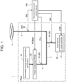
- FIG. 1 is a block diagram illustrating a relationship between a reverse flow power control device 100 according to a first embodiment and a plant 1 targeted by the reverse flow power control device 100.
- the plant 1 targeted by the reverse flow power control device 100 has a renewable energy power generating device ("PV”) 10, a power conditioner (“PCS”) 20, and a load device 30.
- PV renewable energy power generating device
- PCS power conditioner
- the PV 10 is a device that converts natural energy into electric power, which is a photovoltaic power generating device, for example, but the PV 10 is not limited to this.
- the PCS 20 makes direct-current power generated in the PV 10 to be input therein to output alternating-current power, and adjusts a level of the alternating-current power to be output to a predetermined value of equal to or less than an input power level.
- the load device 30 is a device that consumes power, which is a hydrogen producing facility, for example, but the load device 30 is not limited to this.
- the load device 30 has a local controller 31.
- the local controller 31 controls states of respective loads in the load device 30 according to an external load power command, so as to make power to be consumed by the load device 30, namely, load power match a load power command value.
- An in-plant busbar 3 is provided in the plant 1, and the PCS 20 and the load device 30 are connected to the in-plant busbar 3 via connection lines 4, respectively. Further, the in-plant busbar 3 is connected to an external power system 2 via the connection line 4.
- Each connection line 4 is provided with a power meter 50.
- an output power meter 51 is provided to the connection line 4 between the in-plant busbar 3 and the PCS 20
- a load power meter 52 is provided to the connection line 4 between the in-plant busbar 3 and the load device 30
- a transaction power meter 53 is provided to the connection line 4 between the in-plant busbar 3 and the power system 2, by which a flow of power can be measured and monitored.
- the reverse flow power control device 100 accepts outputs of the power meters 50 of the plant 1, namely, outputs from the output power meter 51, the load power meter 52, and the transaction power meter 53, respectively, as an output power actual value 51a, a load power actual value 52a, and a transaction power actual value 53a, and outputs a PCS output command value PCSset and a load command value Lset to the PCS 20 and the load device 30, respectively, of the plant 1.
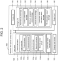
- FIG. 2 is a block diagram illustrating a configuration of the reverse flow power control device 100 according to the first embodiment.
- the reverse flow power control device 100 has an input unit 110, a calculator 120, a storage unit 130, and an output unit 140.
- the reverse flow power control device 100 may also be a combination of individual devices, which is a computer system, for example.
- the input unit 110 accepts not only the output power actual value 51a from the output power meter 51, the load power actual value 52a from the load power meter 52, and the transaction power actual value 53a from the transaction power meter 53 described above, but also the other external input required for control.
- the other external input required for control includes a control parameter of a control circuit to be described later regarding the reverse flow power control device 100, minimum reception power, and planned values of output power and load power.
- the calculator 120 has a control calculator 121, a command value re-calculator 122, and a change rate limiter 123.
- the control calculator 121 performs a control calculation by making the planned values of the output power and the load power, and the output power actual value 51a and the load power actual value 52a accepted by the input unit 110, to be inputted therein, thereby calculating a provisional PCS output command value and a provisional load command value.
- the control calculator 121 has a first subtractor 121a and a first control circuit 121b related to the load command value, and a second subtractor 121c and a second control circuit 121d related to the output command value. Note that although the present embodiment describes a case, as an example, in which the control calculator 121 performs PID control, but another control method may also be employed.
- the command value re-calculator 122 performs re-calculation based on a result of the control calculation performed by the control calculator 121, to thereby calculate the PCS output command value PCSset. Details of the calculator 120 will be described later while referring to FIG. 3 .
- the change rate limiter 123 increases the output of the command value re-calculator 122 to the PCS 20 not rapidly but at a certain inclination, to thereby stabilize the control.
- the storage unit 130 has a planned value storage 131, a control parameter storage 132, a minimum reception power storage 133, an actual value storage 134, a command value calculation result storage 135, and a re-calculation result storage 136.
- the planned value storage 131 stores and houses the planned values of the load power and the output power read by the input unit 110.
- the planned value read by the input unit 110 is a time-series value regarding a time period during which the reverse flow power control device 100 performs the control.
- the input unit 110 sequentially reads planned values regarding a predetermined time width, and in response to this, the planned value storage 131 sequentially houses and stores the planned values.
- the control parameter storage 132 houses and stores a load control parameter P L and an output control parameter P P being control parameters read by the input unit 110.
- the control parameters are, in a case of PID control, for example, a gain, an integral time, and a derivative time.
- the minimum reception power storage 133 houses and stores the minimum reception power read by the input unit 110.
- the actual value storage 134 houses and stores the outputs of the power meters 50 (actual values) read by the input unit 110, namely, the output power actual value 51a, the load power actual value 52a, and the transaction power actual value 53a. These actual values to be stored may be only the values read by the input unit 110 right immediately before the calculation, but values obtained by a given plurality of times of sampling may be housed in chronological order.
- the command value calculation result storage 135 stores the calculation result of the control calculator 121.
- the calculation result to be stored may be only the latest calculation result obtained by the control calculator 121, but the results of a plurality of times of calculation up to the last calculation may be housed in chronological order.
- the re-calculation result storage 136 stores the calculation result of the command value re-calculator 122.
- the calculation result to be stored may be only the latest calculation result obtained by the command value re-calculator 122, but the results of a plurality of times of calculation up to the last calculation may be housed in chronological order.
- the output unit 140 outputs a load command calculation value Lcal (t) being a calculation result of the control calculator 121 to the load device 30 as a load command value Lset (t), and outputs a PCS output command value PCSset (t) being a calculation result of the command value re-calculator 122 to the PCS 20.
- FIG. 3 is a control block diagram illustrating contents of processing performed by the reverse flow power control device 100 according to the first embodiment.
- the processing includes a part related to a command with respect to the load device 30, and a part related to a command with respect to the PCS 20.
- the part related to the command with respect to the load device 30 is as follows.
- the input unit 110 accepts a load planned value Plan-L being a planned value of the load power, and L (t) being the load power actual value 52a from the load power meter 52.
- the value of the load planned value Plan-L is stored in the planned value storage 131, and used as a reference value Lref (t) of the load power at each time point.
- a load controller 121h of the control calculator 121 calculates, based on these signals, the load command calculation value Lcal (t) for giving a load command to the load device 30.
- the load controller 121h has the first subtractor 121a and the first control circuit 121b.
- the first subtractor 121a subtracts the load power actual value L (t) from the load power desired value Lref (t), to thereby output a deviation signal e L (t).
- the first control circuit 121b performs a control calculation based on the deviation signal e L (t), and calculates the load command calculation value Lcal (t) by the following equation (1).
- Lcal t F L Lref t , L t , P L
- F L means that Lcal (t) is a function of Lref (t), L (t), and P L .
- Lcal (t) can be obtained by the following equation (2).
- Lcal t K PL ⁇ e L t + K IL ⁇ ⁇ e L t dt + K DL ⁇ de L t / dt
- K PL , K IL , and K DL are the load control parameters P L read by the input unit 110 and stored in the control parameter storage 132.
- the calculated value of the load command calculation value Lcal (t) is output from the output unit 140 as a load command signal Lset (t) with respect to the local controller 31 of the load device 30.
- the part related to the command with respect to the PCS 20 is as follows.
- the input unit 110 accepts a planned value Plan-P of the output power, and R being the output power actual value 51a from the output power meter 51.
- the value of the planned value Plan-P is stored in the planned value storage 131, and used as a reference value PCSref (t) of the output power at each time point.
- An output controller 121p of the control calculator 121 calculates, based on these signals, the output command calculation value PCScal with respect to the PCS20.
- the output controller 121p has a second subtractor 121c and a second control circuit 121d.
- the second subtractor 121c subtracts the output power actual value PCS (t) from the output power desired value PCSref (t), to thereby output a deviation signal e P (t).
- the second control circuit 121c performs a control calculation based on the deviation signal e P (t), and calculates the output command calculation value PCScal (t) by the following equation (3).
- PCScal t F PCS PCSref t , PCS t , P P
- F PCS means that PCScal (t) is a function of PCSref (t), PCS (t), and P P .
- PCScal (t) can be obtained by the following equation (4).
- PCScal t K PP ⁇ e P t + K IP ⁇ ⁇ e P t dt + K DP ⁇ de P t / dt
- K PP , K IP , and K DP are the output control parameters P P read by the input unit 110 and stored in the control parameter storage 132.
- the command value re-calculator 122 calculates, based on the output command calculation value PCScal (t) calculated by the output controller 121p, the load command calculation value Lcal (t) calculated by the load controller 121h, and a minimum reception power value Rmin housed in the minimum reception power storage 133 of the storage unit 130, the output command value PCSset (t) in order to prevent a reception power value R (t) from the system from becoming less than the minimum reception power value Rmin.
- the reception power value R (t) is a value obtained by subtracting the output power value PCS (t) from a load power value L (t).
- the output command value PCSset (t) calculated by the command value re-calculator 122 is limited by the change rate limiter 123 so that the change rate, namely, a rate of change of the value becomes a predetermined value or less, and then output as the output command value PCSset (t) to the PCS 20 from the output unit 140.
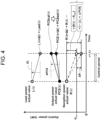
- FIG. 4 is a conceptual graph for explaining details of re-calculation of the output command value in a reverse flow power control method according to the first embodiment.
- a horizontal axis indicates a time, and a vertical axis indicates each electric power (kW).
- ⁇ t is a time width of a control step, namely, a control period.
- FIG. 4 illustrates a case where a calculation period, namely, a calculation step time width matches the control period ⁇ t. Specifically, actual values of respective powers are obtained at a time t, and after performing the calculation, a command value is output at the next control step time (t + ⁇ t). Details will be described hereinbelow.
- the load command value Lset (t) is calculated by the load controller 121h.
- the local controller 31 of the load device 30 upon receiving the load command value Lset (t), the local controller 31 of the load device 30 performs control so that a load power value L (t + ⁇ t) used by the load device 30 matches the value of the load command value Lset (t). Therefore, at the next control step time (t + ⁇ t), the value of the load power value L (t + ⁇ t) can be approximated to the value of the load command value Lset (t).
- ⁇ L a rising width of the load power after ⁇ t (L (t + ⁇ t) - L (t)
- the output command calculation value PCScal (t) is calculated by the output controller 121p.
- the PCS 20 receives the output command of this value, it performs control so that an output power value PCS (t + ⁇ t) matches this value PCScal (t). Therefore, in this case, at the next control step time (t + ⁇ t), the value of the output power value PCS (t + ⁇ t) can be approximated to this value PCScal (t).
- ⁇ PCS a rising width of the output power after ⁇ t in this case
- the command value re-calculator 122 calculates, based on the command values capable of being approximated as respective prediction values at the next control step time (t + ⁇ t), namely, the load command value Lset (t) and the output command calculation value PCScal (t), and the reception power value R (t), the PCS output command value PCSset (t) being an output command value that prevents the prediction value R (t) of the reception power from becoming less than the minimum reception power value Rmin.
- PCSset (t) H PCScal t , PCS t , Lcal t , L t , R t , Rmin
- FIG. 5 is a flow chart illustrating a procedure of the reverse flow power control method according to the first embodiment.
- the procedure of the reverse flow power control method will be described while citing FIG. 5 .
- step S10 reading of parameters is performed (step S10).
- the input unit 110 reads the load control parameter P L , and the control parameter storage 132 stores the parameter (step S11). Further, the input unit 110 reads the output control parameter P P , and the control parameter storage 132 stores the parameter (step S12). Further, the input unit 110 reads the minimum reception power value Rmin, and the minimum reception power storage 133 stores the value (step S13).
- the input unit 110 reads the load planned value Plan-L and the output planned value Plan-P, and the planned value storage 131 stores the values (step S21). Further, the input unit 110 accepts the load power actual value L (t) and the output power actual value PCS (t) as the power actual values, and the actual value storage 134 stores the values (step S22). Note that the reception power value R (t) obtained by subtracting the output power actual value PCS (t) from the load power actual value L (t) is also housed in the actual value storage 134.
- the control calculator 121 of the calculator 120 calculates the command values (step S30).
- the load controller 121h of the control calculator 121 calculates the load command calculation value Lcal (t) (step S31).
- the obtained load command calculation value Lcal (t) is output as the load command value Lset (t) to the local controller 31 of the load device 30, as will be described later (step S60).
- the output controller 121p of the control calculator 121 calculates the output command value calculation value PCScal (t) (step S32). These calculated load power command value Lset (t) and output command value calculation value PCScal (t), and the reception power value R (t) obtained by subtracting the output command value calculation value PCScal (t) from the load command calculation value Lcal (t), are housed and stored in the command value calculation result storage 135.
- the command value re-calculator 122 performs re-calculation by using the respective power actual values housed in the actual value storage 134 and the calculation result housed in the command value calculation result storage 135, to thereby calculate the PCS output command value PCSset (t) (step S50).
- This result is output as the output command value PCSset (t) to the PCS 20 from the output unit 140 via the change rate limiter 123.
- the load command calculation value Lcal (t) obtained in step S30 is output as the load command value Lset (t) to the local controller 31 of the load device 30 (step S60).
- the calculator 120 described above performs the calculation regarding absolute values of the load power and the output power, namely, the values of the load power and the output power themselves, the calculation is not limited to this.
- change amounts from the actual values ⁇ L, ⁇ PCS, and the like
- Lset the load power command value
- PCScal the output command value
- PCSset the output command value
- absolute values of the load power command value and the output power command value are calculated in the output unit 140.
- the calculation by the change amounts, not the absolute values of the command calculation value and the command value as described above can further simplify the calculation.
- the output command value PCSset (t) is calculated by using the min function based on one minimum reception power value Rmin, but the embodiment is not limited to this.
- a plurality of threshold values as a substitute for the minimum reception power are read by the input unit 110 and then housed in the minimum reception power storage 133, change amounts up to the respective threshold values are calculated, and the command value re-calculator 122 calculates an average value, a median value, or a maximum value of the change amounts.
- the control calculation result is not output as it is to the PCS 20, but the re-calculation is performed in order to prevent the reception power value R (t) from becoming less than the minimum reception power value Rmin. As a result of this, it is possible to prevent the reverse flow from the plant 1 to the power system 2.
- FIG. 6 is a block diagram illustrating a configuration of a reverse flow power control device 100a according to a second embodiment.
- the present embodiment is a modification of the first embodiment, and relates to a case where there exists a dead time in a response of a part or all of the renewable energy power generating device (PV) 10, the power conditioner (PCS) 20, and the load device 30.
- PV renewable energy power generating device
- PCS power conditioner
- a calculator 120a further has a calculation interval adjustment part 124, and a storage unit 130a further has a dead time storage 137.
- the input unit 110 accepts dead time DLi information as an external input, and the dead time storage 137 stores this information. Further, the actual value storage 134 stores respective pieces of power actual value data of at least (M + 1) times of calculation to be described later.
- the dead time DLi information (i 1 to 3) of each of the PV 10, the PCS 20, and the load device 30, a maximum value thereof is set as the dead time DL.
- the calculation interval adjustment part 124 calculates, based on the dead time DL and a normal calculation time interval ⁇ tn, a calculation interval ⁇ t by using the following equation (7) and equation (8).
- ROUND (DL / ⁇ tn, 0) is for rounding up digits after a decimal point of a numeric value of (DL / ⁇ tn) to form an integer.
- FIG. 7 is a conceptual graph for explaining details of re-calculation of an output command value in a reverse flow power control method according to the second embodiment.
- FIG. 7 illustrates a case, as an example, in which a calculation of five steps is performed regarding the dead time DL, namely, the above-described (M + 1) is 5.
- the second embodiment is different from the first embodiment in that it performs a calculation of the load command calculation value Lcal by the load controller 121h, a calculation of the output command calculation value PCScal by the output controller 121p, and a calculation of the reception power value R, at the initial four steps, as represented by the following equation (9) to equation (12), and then performs a calculation of output command in the command value re-calculator 122 after the lapse of dead time, namely, at the fifth step, as represented by the following equation (13).
- the dead time in the PCS 20 is shorter than that in the load device 30.
- FIG. 8 is a block diagram illustrating a configuration of a reverse flow power control device 100b according to a third embodiment.
- the present embodiment is a modification of the first embodiment, and takes a response characteristic of each of the renewable energy power generating device (PV) 10, the power conditioner (PCS) 20, and the load device 30 into consideration.
- PV renewable energy power generating device
- PCS power conditioner
- the input unit 110 accepts characteristic models obtained by modeling these response characteristics, as an external input.
- a storage unit 130b further has a characteristic model storage 138 that stores these characteristic models.
- a calculator 120b further has a prediction value calculator 125 that calculates prediction values of response by using these characteristic models.
- the prediction value calculator 125 has an output prediction value calculator 125a and a load prediction value calculator 125b.
- Each characteristic model may be a single characteristic table or a combination of characteristic tables.
- a calculation of an output prediction value PCSpd (t + ⁇ t) by the output prediction value calculator 125a and a calculation of a load prediction value Lpd (t + ⁇ t) by the load prediction value calculator 125b may be performed by the form of functions as represented by the following equation (16) and equation (17), respectively.
- PCSpd t + ⁇ t F P PCScal t
- q P Lpd t + ⁇ t F L Lcal t ,q L
- q P and q L are a set of constants related to respective characteristics (characteristic constants). For example, they are a time constant and a gain in a case of first-order lag or second-order lag.
- the calculation of the output prediction value PCSpd (t + ⁇ t) by the output prediction value calculator 125a and the calculation of the load prediction value Lpd (t + ⁇ t) by the load prediction value calculator 125b are not limited to be performed as described above and may be performed linearly or nonlinearly as long as it is possible to predict future power with respect to a command value for each device, and it is possible to use, for example, a prediction method of deep learning such as a neural network or a random forest using a tree structure.
- FIG. 9 is a control block diagram illustrating a configuration and operations of the reverse flow power control device 100b according to the third embodiment.
- the load controller 121h of the control calculator 121 calculates the load command calculation value Lcal (t), and the output unit 140 outputs this value as the load command value Lset (t), to thereby enable operations similar to those of the first embodiment.
- the load prediction value calculator 125b calculates the load prediction value Lpd (t + ⁇ t) by using the load command calculation value Lcal (t) calculated by the load controller 121h.
- the output prediction value calculator 125a calculates the output prediction value PCSpd (t + ⁇ t) by using the output command calculation value PCScal (t) calculated by the output controller 121p.
- the command value re-calculator 122 calculates, based on respective prediction values at the next control step time (t + ⁇ t), namely, the load prediction value Lpd (t + ⁇ t) and the output prediction value PCSpd (t + ⁇ t), and the reception power value R (t), the PCS output command value PCSset (t) being an output command value that prevents the prediction value R (t + ⁇ t) of the reception power from becoming less than the minimum reception power value Rmin.
- PCSset (t) is calculated based on the respective prediction values by using the following equation (18), instead of the equation (5) in the first embodiment.
- PCSset t H PCSpd t ,PCS t ,Lpd t ,L t ,R t ,Rmin
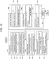
- FIG. 10 is a flow chart illustrating a procedure of a reverse flow power control method according to the third embodiment.
- the procedure up to step S30 is similar to that of the first embodiment.
- only a part different from that of the first embodiment will be described.
- the present embodiment further has a prediction value calculation step (step S40). Specifically, the load prediction value calculator 125b performs a load power prediction value calculation to calculate a load prediction value Lpd (t + ⁇ t) (step S41), and the output prediction value calculator 125a performs an output power prediction value calculation to calculate an output prediction value PCSpd (t + ⁇ t) (step S42).
- the PCS output command value PCSset (t) is calculated based on the respective prediction values by using the equation (19), instead of the equation (5) in the first embodiment.
- the present embodiment it is possible to obtain an effect similar to that of the first embodiment. Further, by predicting future power by using the models of the respective devices, an influence due to the characteristics of the respective devices can be considered, which enables to further securely reduce the possibility that the reception power becomes less than the minimum reception power.
- FIG. 11 is a block diagram illustrating a relationship between a reverse flow power control device 100c according to a fourth embodiment and a plant 1c targeted by the reverse flow power control device 100c.
- the present embodiment is a modification of the first embodiment, and the plant 1c further has a storage battery 40 and a charge/discharge power meter 54.
- FIG. 12 is a block diagram illustrating a configuration of the reverse flow power control device 100c according to the fourth embodiment.
- the reverse flow power control device 100c further has a storage battery controller 121q.
- a command value re-calculator 122c is provided instead of the command value re-calculator 122 in the first embodiment, and a re-calculation target is not the output command value with respect to the PCS 20 in the first embodiment but a charge/discharge command value with respect to the storage battery 40.
- a part other than the above is similar to that of the first embodiment.
- a part different from that of the first embodiment will be mainly described, and an explanation of a part similar to that of the first embodiment will be omitted.
- FIG. 13 is a conceptual graph for explaining details of re-calculation of an output command value in a reverse flow power control method according to the fourth embodiment.
- the output command calculation value PCScal (t) calculated by the output controller 121p is output as the output command value PCSset (t) from the output unit 140 to the PCS 20.
- the storage battery controller 121q calculates a charge/discharge command calculation value BATcal (t) of the storage battery 40 through a control calculation.
- a change amount of the charge/discharge command calculation value BATcal (t) with respect to a charge/discharge actual value BAT (t) of the storage battery 40 is set to ⁇ BAT.
- ⁇ BAT if the change is in the case of charge, ⁇ BAT is positive, and if the change is in the case of discharge, ⁇ BAT is negative.
- the command value re-calculator 122c calculates, based on the command values capable of being approximated as respective prediction values at the next control step time (t + ⁇ t), namely, the load command calculation value Lcal (t), the output command calculation value PCScal (t), and the charge/discharge command calculation value BATcal (t), and the respective actual values, a charge/discharge command value BATset (t) being a charge/discharge command value that prevents the prediction value R (t) of the reception power from becoming less than the minimum reception power value Rmin.
- the charge/discharge command value BATset (t) is calculated by the following equation (20).
- BATset t G PCScal t ,PCS t ,Lcal t ,L t , BATset t BAT t ,R t ,Rmin
- Equation (20) can be represented as the following equation (21).
- BATset t BAT t ⁇ Lcal t ⁇ L t + PCSset t ⁇ PCS t ⁇ min ⁇ Lcal t ⁇ L t + PCSset t ⁇ PCS t ⁇ BATcal t ⁇ BAT t , R t ⁇ Rmin
- the storage battery 40 is provided, so that by charging the power generated by the PV 10 in the storage battery 40 without being suppressed by the PCS 20, the renewable energy can be used maximally.
- the reverse flow power control device 100c outputs the charge/discharge command value BATset (t) after re-calculating the command value with respect to the storage battery 40 while setting the minimum reception power value Rmin as a condition. As a result of this, it is possible to avoid a situation in which the reception power value R (t) becomes less than the minimum reception power value Rmin or a reverse flow occurs due to a control delay.
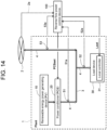
- FIG. 14 is a block diagram illustrating a relationship between a reverse flow power control device 100d according to a fifth embodiment and a plant 1 targeted by the reverse flow power control device 100d.
- the present embodiment is a modification of the first embodiment, and is an embodiment in a case where reverse flow power from the plant 1 to the power system 2 is allowed under a certain condition. Accordingly, when the reverse flow power is allowed, a reverse flow allowance signal 2a is sent from the power system 2 to the reverse flow power control device 100d.
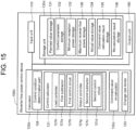
- FIG. 15 is a block diagram illustrating a configuration of the reverse flow power control device 100d according to the fifth embodiment.
- the input unit 110 accepts the reverse flow allowance signal 2a sent from the power system 2.
- the reverse flow allowance signal 2a includes an allowed time zone ⁇ Tp during which the reverse flow is allowed, and a maximum reverse flow power value Smax being an upper limit value of the reverse flow at that time.
- a storage unit 130d further has a maximum reverse flow power storage 139 that houses and stores the allowed time zone ⁇ Tp and the maximum reverse flow power value Smax accepted by the input unit 110.
- a calculator 120d further has a control condition determination part 126.
- the control condition determination part 126 designates either of two control states (a first control state and a second control state), based on the allowed time zone ⁇ Tp and the maximum reverse flow power value Smax housed in the storage unit 130d.
- a command value re-calculator 122d performs processing according to the respective control states.
- the first control state corresponds to a case where the reverse flow is not allowed, in the same manner as in the first embodiment.
- the command value re-calculator 122d calculates, based on the output command calculation value PCScal (t) calculated by the output controller 121p, the load command calculation value Lcal (t) calculated by the load controller 121h, and the minimum reception power value Rmin housed in the minimum reception power storage 133 of the storage unit 130, the output command value PCSet (t) in order to prevent the reception power value R (t) from the system from becoming less than the minimum reception power value Rmin.
- the second control state corresponds to a case where the reverse flow is allowed in the allowed time zone ⁇ Tp based on the reverse flow allowance signal 2a sent from the power system 2.
- the command value re-calculator 122d calculates, based on the output command calculation value PCScal (t) calculated by the output controller 121p, the load command calculation value Lcal (t) calculated by the load controller 121h, and the maximum reverse flow power value Smax housed in the maximum reverse flow power storage 139 of the storage unit 130, the output command value PCSset (t) using the following equation (22), in order to prevent reverse flow power S (t) with respect to the system from exceeding the maximum reverse flow power value Smax.
- PCSset t H PCScal t , PCS t , Lcal t , L t , S t , Smax
- the equation (22) can be represented as the following equation (23).
- PCSset t PCS t + min ⁇ ⁇ L + ⁇ PCS
- S t ⁇ Smax + ⁇ L PCS t + min ⁇ Lcal t ⁇ L t + PCSset t ⁇ PCS t , S t ⁇ Smax + Lcal t ⁇ L t
- the reverse flow allowance signal 2a includes the allowed time zone ⁇ Tp during which the reverse flow is allowed, and the maximum reverse flow power value Smax being the upper limit value of the reverse flow at that time, is described as an example, but not limited to this.
- the reverse flow allowance signal 2a from the power system 2 may include only the maximum reverse flow power value Smax.
- the control condition determination part 126 can designate the first control state during a period of time in which the reverse flow allowance signal 2a from the power system 2 is not sent, and it can designate the second control state during a period of time in which the signal is sent.
Landscapes
- Engineering & Computer Science (AREA)
- Power Engineering (AREA)
- Physics & Mathematics (AREA)
- Electromagnetism (AREA)
- General Physics & Mathematics (AREA)
- Radar, Positioning & Navigation (AREA)
- Automation & Control Theory (AREA)
- Supply And Distribution Of Alternating Current (AREA)
Claims (8)
- Rückwärtsflussleistungssteuerungsvorrichtung (100) zum Verhindern eines Auftretens einer Rückwärtsflussleistung von einer Anlage mit einer Erneuerbare-Energie-Stromerzeugungsvorrichtung (10), einen Leistungsregler (20), der in der Lage ist, die Ausgangsleistung der Erneuerbare-Energie-Stromerzeugungsvorrichtung (10) anzupassen, und einer Lastvorrichtung (30), und die mit einem externen Leistungssystem (2) verbunden ist, zum Leistungssystem (2), wobei die Rückwärtsflussleistungssteuerungsvorrichtung (100) umfasst:eine Eingabeeinheit (110), die konfiguriert ist, tatsächliche Werte der Ausgangsleistung, der Lastleistung, die an die Lastvorrichtung (30) bereitgestellt wird, und der Empfangsleistung, die von der Anlage von dem Leistungssystem (2) empfangenen wird, und eine Information, umfassend einen minimalen Empfangsleistungswert, der ein Minimalwert der Empfangsleistung ist, zu akzeptieren;eine Speichereinheit (130), die konfiguriert ist, die von der Eingabeeinheit (110) akzeptierte Information zu speichern;einen Rechner (120), der konfiguriert ist, eine Berechnung von Anweisungswerten der Ausgangsleistung und der Lastleistung basierend auf der Information und den jeweiligen tatsächlichen Werten, die in der Speichereinheit (130) gespeichert sind, durchzuführen; undeine Ausgabeeinheit (140), die konfiguriert ist, die Anweisungswerte an die Lastvorrichtung (30) und den Leistungsregler (20) auszugeben, wobeider Rechner (120) umfasst:eine Ausgabesteuerung (121p), der konfiguriert ist, einen Ausgabeanweisungsberechnungswert zu berechnen;einen Laststeuerungsrechner (121h), der konfiguriert ist, einen Lastanweisungsberechnungswert zu berechnen;einen Anweisungswertneuberechner (122), der konfiguriert ist, unter Verwendung der entsprechenden tatsächlichen Werte, des Ausgabeanweisungsberechnungswerts, des Lastanweisungsberechnungswerts und des minimalen Empfangsleistungswerts einen Ausgabeanweisungswert in Bezug auf den Leistungsregler (20) zu berechnen, um zu verhindern, dass ein Empfangsleistungswert, der ein Wert der Empfangsleistung ist, kleiner als der minimale Empfangsleistungswert wird; undein Berechnungsintervallanpassungsteil (124), das konfiguriert ist, ein Berechnungsintervall zum Erzeugen einer Vielzahl von Berechnungsschritten in Bezug auf eine Totzeit in der Erneuerbare-Energie-Stromerzeugungsvorrichtung (10), dem Leistungsregler (20) und der Lastvorrichtung (30) einzustellen; wobeider Anweisungswertneuberechner (122) ferner konfiguriert ist, eine Änderung des Empfangsleistungswerts in einem Intervall bis zu einem Ende der Vielzahl von Berechnungsschritten zu berechnen, in dem eine Anweisung durch die Totzeit reflektiert wird, und den Befehlswert für die Ausgabe zu berechnen, der verhindert, dass der Empfangsleistungswert kleiner als der minimale Empfangsleistungswert wird.
- Rückwärtsflussleistungssteuerungsvorrichtung (100) gemäß Anspruch 1, wobei:die Speichereinheit (130) ferner einen Charakteristikmodellspeicher (138) aufweist, der konfiguriert ist, charakteristische Modelle zu speichern, die von der Eingabeeinheit (110) akzeptiert und durch Modellierung von Reaktionscharakteristiken der Erneuerbare-Energie-Stromerzeugungsvorrichtung (10), dem Leistungsregler (20) und der Lastvorrichtung (30) erhalten werden;der Rechner (120) ferner einen Ausgabevorhersagewertrechner (125a) und einen Lastvorhersagewertrechner der Last (125b) umfasst, die konfiguriert sind, jeweils einen Ausgabevorhersagewert und einen Lastvorhersagewert basierend auf dem Ausgabeanweisungsberechnungswert, dem Lastanweisungsberechnungswert, und den charakteristischen Modellen zu berechnen; undder Anweisungswertneuberechner (122) ferner konfiguriert ist, unter Verwendung der entsprechenden tatsächlichen Werte, des Ausgabevorhersagewerts, des Lastvorhersagewerts, und des minimalem Empfangsleistungswerts den Ausgabeanweisungswert in Bezug auf den Leistungsregler (20) zu berechnen, um zu verhindern, dass der Empfangsleistungswert unter den minimalen Empfangsleistungswert fällt.
- Rückwärtsflussleistungssteuerungsvorrichtung (100) gemäß Anspruch 1, wobei
die Speichereinheit (130) ferner konfiguriert ist, nicht nur den minimalen Empfangsleistungswert, sondern auch eine Vielzahl von Schwellenwerten zu speichern; und
der Anweisungswertneuberechner (122) ferner konfiguriert ist, den Anweisungswert in Bezug auf den Leistungsregler (20) zu berechnen, um die Rückflussleistung durch eine Berechnung unter Verwendung der Vielzahl von Schwellenwerten zu verhindern. - Rückwärtsflussleistungssteuerungsvorrichtung (100) gemäß Anspruch 3, wobei
in der Berechnung unter Verwendung der Vielzahl von Schwellenwerten der Anweisungswertneuberechner (122) ferner konfiguriert ist, den Anweisungswert unter Verwendung eines Maximalwerts, eines Minimalwerts, eines Durchschnittswerts, oder eines Medianwerts zu berechnen. - Rückwärtsflussleistungssteuerungsvorrichtung (100) gemäß Anspruch 1, wobei
der Anweisungswertneuberechner (122) ferner konfiguriert ist, um die Berechnung basierend auf einem Änderungsbetrag von den jeweiligen tatsächlichen Werten durchzuführen. - Rückwärtsflussleistungssteuerungsvorrichtung (100) gemäß Anspruch 1, wobei:
die Anlage ferner eine Speicherbatterie aufweist; und
der Anweisungswertneuberechner (122) ferner konfiguriert ist, unter Verwendung der entsprechenden tatsächlichen Werte, des Ausgabeanweisungsberechnungswerts, des Lastanweisungsberechnungswerts, und des minimalen Empfangsleistungswerts, eines Lade-/Entladeanweisungswerts in Bezug auf die Speicherbatterie zu berechnen, um zu verhindern, dass der Empfangsleistungswert kleiner als der minimale Empfangsleistungswert wird. - Rückwärtsflussleistungssteuerungsvorrichtung (100) gemäß einem der Ansprüche 1 bis 6, wobei
die Anlage einen Rückwärtsfluss zum Leistungssystem (2) unter einer Bedingung verursachen kann, bei der ein Leistungswert des Rückwärtsflusses einen maximalen Rückwärtsflussleistungswert nicht überschreitet, wobei
der Anweisungswertneuberechner (122) ferner konfiguriert ist, in zulässigen Fällen, unter Verwendung der jeweiligen tatsächlichen Werte, den Ausgabeanweisungsberechnungswert, den Lastanweisungsberechnungswert, und den minimalen Empfangsleistungswert, den Ausgabeanweisungswert in Bezug auf den Leistungsregler (20) zu berechnen, um zu verhindern, dass der Leistungswert des Rückflusses den maximalen Rückwärtsflussleistungswert überschreitet. - Rückwärtsflussleistungssteuerungsverfahren, das verhindert, dass Rückwärtsflussleistung von einer Anlage mit einer Erneuerbare-Energie-Stromerzeugungsvorrichtung (10), einem Leistungsregler (20), der in der Lage ist, die Ausgangsleistung der Erneuerbare-Energie-Stromerzeugungsvorrichtung (10) anzupassen, und einer Lastvorrichtung (30), die mit einem externen Leistungssystem (2) verbunden ist, zum Leistungssystem (2) fließt, wobei das Rückwärtsflussleistungssteuerungsverfahren Folgendes umfasst:einen Externe-Informationen-Akzeptierungsschritt, in dem eine Eingabeeinheit (110) tatsächliche Werte der Ausgangsleistung, der Lastleistung, die der Lastvorrichtung (30) zugeführt wird, und der Empfangsleistung, die von der Anlage von dem Leistungssystem (2) empfangen wird, und eine Information, umfassend einen minimalen Empfangsleistungswert, der ein Minimalwert der Empfangsleistung ist, akzeptiert, und eine Speichereinheit (130) die Information speichert;einen Anweisungswertberechnungsschritt, in dem eine Ausgangssteuerung (121p) einen Ausgangssteuerungsberechnungswert berechnet und eine Laststeuerung (121h) einen Laststeuerungsberechnungswert berechnet, basierend auf der Information und den jeweiligen tatsächlichen Werten, die in der Speichereinheit (130) enthalten sind;einen Ausgabeanweisungswertneuberechnungsschritt, in dem ein Anweisungswertneuberechner (122) unter Verwendung der entsprechenden tatsächlichen Werte den Ausgabeanweisungsberechnungswert, den Lastanweisungsberechnungswert, und den minimalen Empfangsleistungswert, einen Ausgabeanweisungswert in Bezug auf den Leistungsregler (20) berechnet, um zu verhindern, dass ein Empfangsleistungswert, der ein Wert der Empfangsleistung ist, kleiner als der minimale Empfangsleistungswert wird; undeinen Ausgabeschritt, in dem eine Ausgabeeinheit (140) die Anweisungswerte an die Ausgabevorrichtung (30) und den Leistungsregler (20) ausgibt, wobeider Ausgabeanweisungswertneuberechnungsschritt umfasst:einen Schritt durch einen Berechnungsintervallanpassungsteil (124) zum Einstellen eines Berechnungsintervalls zum Erzeugen einer Vielzahl von Berechnungsschritten in Bezug auf eine Totzeit in der Erneuerbare-Energie-Stromerzeugungsvorrichtung (10), des Leistungsreglers (20), und der Lastvorrichtung (30); undeinen Schritt durch den Anweisungswertneuberechner (122) zum Berechnen einer Änderung des Empfangsleistungswerts in einem Intervall bis zu einem Ende der Vielzahl von Berechnungsschritten, in denen ein Anweisungswert durch die Totzeit reflektiert wird, und zum Berechnen des Ausgabeanweisungswerts, der verhindert, dass der Empfangsleistungswert kleiner als der minimale Empfangsleistungswert wird.
Applications Claiming Priority (1)
| Application Number | Priority Date | Filing Date | Title |
|---|---|---|---|
| JP2022099728A JP7797316B2 (ja) | 2022-06-21 | 2022-06-21 | 逆潮流電力制御装置および逆潮流電力制御方法 |
Publications (2)
| Publication Number | Publication Date |
|---|---|
| EP4300751A1 EP4300751A1 (de) | 2024-01-03 |
| EP4300751B1 true EP4300751B1 (de) | 2025-02-19 |
Family
ID=86899195
Family Applications (1)
| Application Number | Title | Priority Date | Filing Date |
|---|---|---|---|
| EP23179971.9A Active EP4300751B1 (de) | 2022-06-21 | 2023-06-19 | Vorrichtung zur steuerung der rückwärtsflussleistung und verfahren zur steuerung der rückwärtsflussleistung |
Country Status (3)
| Country | Link |
|---|---|
| US (1) | US12603510B2 (de) |
| EP (1) | EP4300751B1 (de) |
| JP (1) | JP7797316B2 (de) |
Family Cites Families (24)
| Publication number | Priority date | Publication date | Assignee | Title |
|---|---|---|---|---|
| JPS63239513A (ja) * | 1987-03-27 | 1988-10-05 | Toshiba Corp | 太陽光発電システムの制御方法 |
| JP2002204531A (ja) | 2000-10-31 | 2002-07-19 | Canon Inc | 交流連系装置およびその制御方法 |
| AU2005242329B2 (en) | 2004-04-30 | 2008-05-29 | Interdigital Technology Corporation | Method and apparatus for minimizing redundant enhanced uplink allocation requests and fault-isolating enhanced uplink transmission failures |
| KR101116428B1 (ko) * | 2010-07-14 | 2012-03-05 | 삼성에스디아이 주식회사 | 에너지 저장 시스템 |
| JP5907753B2 (ja) * | 2011-02-28 | 2016-04-26 | 積水化学工業株式会社 | 地域内電力需要管理システム |
| US9735591B2 (en) * | 2012-02-27 | 2017-08-15 | Kyocera Corporation | Control apparatus, control system, and storage battery control method |
| JPWO2014007368A1 (ja) * | 2012-07-06 | 2016-06-02 | 日本電気株式会社 | 電力ネットワークシステム、電力ネットワークシステムの制御方法、及び制御プログラム |
| WO2014034391A1 (ja) * | 2012-09-03 | 2014-03-06 | 株式会社 東芝 | エネルギー管理システム、サーバ、エネルギー管理方法および記憶媒体 |
| JP2014150641A (ja) * | 2013-01-31 | 2014-08-21 | Toshiba Corp | エネルギー管理システム、エネルギー管理方法、プログラムおよびサーバ装置 |
| WO2015103677A1 (en) * | 2014-01-13 | 2015-07-16 | Gng Electrical Pty Ltd | Zero export relay |
| JP6404758B2 (ja) * | 2015-03-27 | 2018-10-17 | 京セラ株式会社 | 電力変換装置及び電力管理装置 |
| JP6703447B2 (ja) * | 2015-07-17 | 2020-06-03 | 積水化学工業株式会社 | 電力データ管理システム、需要家集合体及び電力融通街区 |
| JP6559247B2 (ja) * | 2015-09-29 | 2019-08-14 | 京セラ株式会社 | 蓄電システム、蓄電装置及び蓄電システムの制御方法 |
| WO2017056502A1 (ja) * | 2015-09-29 | 2017-04-06 | 京セラ株式会社 | 電源装置、分散電源システム及びその制御方法 |
| WO2017138629A1 (ja) * | 2016-02-12 | 2017-08-17 | 日本電気株式会社 | 充放電制御システム、充放電制御方法及びプログラム |
| US10211639B2 (en) * | 2016-05-20 | 2019-02-19 | Abb Schweiz Ag | Padmount transformer with energy storage apparatus |
| CN109075717B (zh) * | 2016-09-14 | 2021-06-08 | 法拉达伊格里德有限公司 | 配电网络和过程 |
| JP6414870B1 (ja) * | 2018-04-18 | 2018-10-31 | 松尾建設株式会社 | 逆潮流防止型自家消費用再エネ発電蓄電制御装置 |
| JP7513529B2 (ja) * | 2019-02-05 | 2024-07-09 | 株式会社カネカ | 電力制御システムおよび電力制御方法 |
| JP2020171120A (ja) | 2019-04-03 | 2020-10-15 | トヨタ自動車株式会社 | 二次電池の充電方法 |
| WO2020203993A1 (ja) * | 2019-04-03 | 2020-10-08 | 株式会社Ihi | 電力管理システム |
| JP7345371B2 (ja) * | 2019-11-27 | 2023-09-15 | 京セラ株式会社 | 電力管理装置、電力管理方法及び電力管理プログラム |
| EP4094340B1 (de) * | 2020-01-22 | 2025-05-14 | Vestas Wind Systems A/S | Steuerung eines kraftwerks für erneuerbare energien als reaktion auf ein null-leistungsbedarfssignal |
| JP7533524B2 (ja) * | 2022-05-10 | 2024-08-14 | 株式会社Ihi | 電力制御装置、電力制御方法及び電力制御プログラム |
-
2022
- 2022-06-21 JP JP2022099728A patent/JP7797316B2/ja active Active
-
2023
- 2023-06-16 US US18/336,572 patent/US12603510B2/en active Active
- 2023-06-19 EP EP23179971.9A patent/EP4300751B1/de active Active
Also Published As
| Publication number | Publication date |
|---|---|
| US20230409067A1 (en) | 2023-12-21 |
| JP2024000807A (ja) | 2024-01-09 |
| JP7797316B2 (ja) | 2026-01-13 |
| US12603510B2 (en) | 2026-04-14 |
| EP4300751A1 (de) | 2024-01-03 |
Similar Documents
| Publication | Publication Date | Title |
|---|---|---|
| Kamarposhti et al. | Effect of wind penetration and transmission line development in order to reliability and economic cost on the transmission system connected to the wind power plant | |
| Wang et al. | Coordinated predictive control for wind farm with BESS considering power dispatching and equipment ageing | |
| Raducu et al. | Design and implementation of a hybrid power plant controller | |
| CN120454200A (zh) | 一种源网荷储资源的协同互动智能调控方法 | |
| US20220220938A1 (en) | Method for controlling a renewable energy farm in compliance with obligations towards a power grid | |
| Wang et al. | Preventive primary frequency response control of energy storage systems for a high renewable penetrated power grid | |
| EP4300751B1 (de) | Vorrichtung zur steuerung der rückwärtsflussleistung und verfahren zur steuerung der rückwärtsflussleistung | |
| CN120806299B (zh) | 建筑微电网多元协同优化方法、系统、电子设备及介质 | |
| Rai et al. | An optimisation model to determine the capacity of a distributed energy resource to contract with a balancing services aggregator | |
| Yang et al. | An economic optimization for BESS sizing in a hybrid PV and wind power plant | |
| CN120200293A (zh) | 基于平抑波动的储能电站能量管理控制方法 | |
| CN119853072A (zh) | 一种新能源场站结合储能的日前日内双时间尺度电力系统调压方法及系统 | |
| Dutrieux et al. | An energy supervision for distributed storage systems to optimize the provision of multiple services | |
| Zhu et al. | Resonance area-based PMSG controller optimization under energy scenario variations | |
| CN119518697A (zh) | 基于负荷预测的参数修正方法、装置、电子设备、存储介质 | |
| Haines et al. | The impact of co-located clusters of inverter-based resources on a performance-based regulation market metric | |
| Sheridan et al. | A techno-economic evaluation of battery energy storage systems co-located with wind in the Irish integrated electricity market | |
| Cagnano et al. | Microturbine control strategy for the load-following service provision | |
| CN120414738B (zh) | 一种区域电网交流断面送出入功率限值的确定方法、装置、电子设备及存储介质 | |
| CN111817305B (zh) | 一种输变电设备增容的电网运行效能后评估方法及系统 | |
| CN120049487B (zh) | 一种基于新能源外送通道的风光储优化配置方法及系统 | |
| US20250070556A1 (en) | Providing secondary frequency regulation support to a power transmission system using behind-the-meter energy resources and substation battery | |
| CN121566443A (zh) | 一种考虑源荷双端不确定性的电力系统连锁故障链建模及阻断方法、装置、系统及介质 | |
| Callec et al. | Ensuring reliability of FCR and aFRR provided by wind & solar | |
| Ohara et al. | A novel control scheme to mitigate fluctuations in a wind farm using battery energy storage and a curtailment function considering communication and control delays |
Legal Events
| Date | Code | Title | Description |
|---|---|---|---|
| PUAI | Public reference made under article 153(3) epc to a published international application that has entered the european phase |
Free format text: ORIGINAL CODE: 0009012 |
|
| STAA | Information on the status of an ep patent application or granted ep patent |
Free format text: STATUS: REQUEST FOR EXAMINATION WAS MADE |
|
| 17P | Request for examination filed |
Effective date: 20230619 |
|
| AK | Designated contracting states |
Kind code of ref document: A1 Designated state(s): AL AT BE BG CH CY CZ DE DK EE ES FI FR GB GR HR HU IE IS IT LI LT LU LV MC ME MK MT NL NO PL PT RO RS SE SI SK SM TR |
|
| GRAP | Despatch of communication of intention to grant a patent |
Free format text: ORIGINAL CODE: EPIDOSNIGR1 |
|
| STAA | Information on the status of an ep patent application or granted ep patent |
Free format text: STATUS: GRANT OF PATENT IS INTENDED |
|
| INTG | Intention to grant announced |
Effective date: 20241008 |
|
| P01 | Opt-out of the competence of the unified patent court (upc) registered |
Free format text: CASE NUMBER: APP_62364/2024 Effective date: 20241122 |
|
| GRAS | Grant fee paid |
Free format text: ORIGINAL CODE: EPIDOSNIGR3 |
|
| GRAA | (expected) grant |
Free format text: ORIGINAL CODE: 0009210 |
|
| STAA | Information on the status of an ep patent application or granted ep patent |
Free format text: STATUS: THE PATENT HAS BEEN GRANTED |
|
| AK | Designated contracting states |
Kind code of ref document: B1 Designated state(s): AL AT BE BG CH CY CZ DE DK EE ES FI FR GB GR HR HU IE IS IT LI LT LU LV MC ME MK MT NL NO PL PT RO RS SE SI SK SM TR |
|
| REG | Reference to a national code |
Ref country code: GB Ref legal event code: FG4D |
|
| REG | Reference to a national code |
Ref country code: CH Ref legal event code: EP |
|
| REG | Reference to a national code |
Ref country code: IE Ref legal event code: FG4D |
|
| REG | Reference to a national code |
Ref country code: DE Ref legal event code: R096 Ref document number: 602023002093 Country of ref document: DE |
|
| REG | Reference to a national code |
Ref country code: NL Ref legal event code: MP Effective date: 20250219 |
|
| PG25 | Lapsed in a contracting state [announced via postgrant information from national office to epo] |
Ref country code: RS Free format text: LAPSE BECAUSE OF FAILURE TO SUBMIT A TRANSLATION OF THE DESCRIPTION OR TO PAY THE FEE WITHIN THE PRESCRIBED TIME-LIMIT Effective date: 20250519 |
|
| PG25 | Lapsed in a contracting state [announced via postgrant information from national office to epo] |
Ref country code: FI Free format text: LAPSE BECAUSE OF FAILURE TO SUBMIT A TRANSLATION OF THE DESCRIPTION OR TO PAY THE FEE WITHIN THE PRESCRIBED TIME-LIMIT Effective date: 20250219 |
|
| PG25 | Lapsed in a contracting state [announced via postgrant information from national office to epo] |
Ref country code: PL Free format text: LAPSE BECAUSE OF FAILURE TO SUBMIT A TRANSLATION OF THE DESCRIPTION OR TO PAY THE FEE WITHIN THE PRESCRIBED TIME-LIMIT Effective date: 20250219 |
|
| PGFP | Annual fee paid to national office [announced via postgrant information from national office to epo] |
Ref country code: DE Payment date: 20250402 Year of fee payment: 3 |
|
| PG25 | Lapsed in a contracting state [announced via postgrant information from national office to epo] |
Ref country code: ES Free format text: LAPSE BECAUSE OF FAILURE TO SUBMIT A TRANSLATION OF THE DESCRIPTION OR TO PAY THE FEE WITHIN THE PRESCRIBED TIME-LIMIT Effective date: 20250219 |
|
| REG | Reference to a national code |
Ref country code: LT Ref legal event code: MG9D |
|
| PG25 | Lapsed in a contracting state [announced via postgrant information from national office to epo] |
Ref country code: IS Free format text: LAPSE BECAUSE OF FAILURE TO SUBMIT A TRANSLATION OF THE DESCRIPTION OR TO PAY THE FEE WITHIN THE PRESCRIBED TIME-LIMIT Effective date: 20250619 Ref country code: NO Free format text: LAPSE BECAUSE OF FAILURE TO SUBMIT A TRANSLATION OF THE DESCRIPTION OR TO PAY THE FEE WITHIN THE PRESCRIBED TIME-LIMIT Effective date: 20250519 |
|
| PG25 | Lapsed in a contracting state [announced via postgrant information from national office to epo] |
Ref country code: NL Free format text: LAPSE BECAUSE OF FAILURE TO SUBMIT A TRANSLATION OF THE DESCRIPTION OR TO PAY THE FEE WITHIN THE PRESCRIBED TIME-LIMIT Effective date: 20250219 |
|
| PG25 | Lapsed in a contracting state [announced via postgrant information from national office to epo] |
Ref country code: HR Free format text: LAPSE BECAUSE OF FAILURE TO SUBMIT A TRANSLATION OF THE DESCRIPTION OR TO PAY THE FEE WITHIN THE PRESCRIBED TIME-LIMIT Effective date: 20250219 |
|
| PG25 | Lapsed in a contracting state [announced via postgrant information from national office to epo] |
Ref country code: PT Free format text: LAPSE BECAUSE OF FAILURE TO SUBMIT A TRANSLATION OF THE DESCRIPTION OR TO PAY THE FEE WITHIN THE PRESCRIBED TIME-LIMIT Effective date: 20250620 Ref country code: LV Free format text: LAPSE BECAUSE OF FAILURE TO SUBMIT A TRANSLATION OF THE DESCRIPTION OR TO PAY THE FEE WITHIN THE PRESCRIBED TIME-LIMIT Effective date: 20250219 |
|
| PG25 | Lapsed in a contracting state [announced via postgrant information from national office to epo] |
Ref country code: GR Free format text: LAPSE BECAUSE OF FAILURE TO SUBMIT A TRANSLATION OF THE DESCRIPTION OR TO PAY THE FEE WITHIN THE PRESCRIBED TIME-LIMIT Effective date: 20250520 Ref country code: BG Free format text: LAPSE BECAUSE OF FAILURE TO SUBMIT A TRANSLATION OF THE DESCRIPTION OR TO PAY THE FEE WITHIN THE PRESCRIBED TIME-LIMIT Effective date: 20250219 |
|
| REG | Reference to a national code |
Ref country code: AT Ref legal event code: MK05 Ref document number: 1769279 Country of ref document: AT Kind code of ref document: T Effective date: 20250219 |
|
| PG25 | Lapsed in a contracting state [announced via postgrant information from national office to epo] |
Ref country code: SE Free format text: LAPSE BECAUSE OF FAILURE TO SUBMIT A TRANSLATION OF THE DESCRIPTION OR TO PAY THE FEE WITHIN THE PRESCRIBED TIME-LIMIT Effective date: 20250219 |
|
| PG25 | Lapsed in a contracting state [announced via postgrant information from national office to epo] |
Ref country code: SM Free format text: LAPSE BECAUSE OF FAILURE TO SUBMIT A TRANSLATION OF THE DESCRIPTION OR TO PAY THE FEE WITHIN THE PRESCRIBED TIME-LIMIT Effective date: 20250219 |
|
| PG25 | Lapsed in a contracting state [announced via postgrant information from national office to epo] |
Ref country code: DK Free format text: LAPSE BECAUSE OF FAILURE TO SUBMIT A TRANSLATION OF THE DESCRIPTION OR TO PAY THE FEE WITHIN THE PRESCRIBED TIME-LIMIT Effective date: 20250219 |
|
| PG25 | Lapsed in a contracting state [announced via postgrant information from national office to epo] |
Ref country code: IT Free format text: LAPSE BECAUSE OF FAILURE TO SUBMIT A TRANSLATION OF THE DESCRIPTION OR TO PAY THE FEE WITHIN THE PRESCRIBED TIME-LIMIT Effective date: 20250219 |
|
| PG25 | Lapsed in a contracting state [announced via postgrant information from national office to epo] |
Ref country code: AT Free format text: LAPSE BECAUSE OF FAILURE TO SUBMIT A TRANSLATION OF THE DESCRIPTION OR TO PAY THE FEE WITHIN THE PRESCRIBED TIME-LIMIT Effective date: 20250219 |
|
| PG25 | Lapsed in a contracting state [announced via postgrant information from national office to epo] |
Ref country code: EE Free format text: LAPSE BECAUSE OF FAILURE TO SUBMIT A TRANSLATION OF THE DESCRIPTION OR TO PAY THE FEE WITHIN THE PRESCRIBED TIME-LIMIT Effective date: 20250219 Ref country code: CZ Free format text: LAPSE BECAUSE OF FAILURE TO SUBMIT A TRANSLATION OF THE DESCRIPTION OR TO PAY THE FEE WITHIN THE PRESCRIBED TIME-LIMIT Effective date: 20250219 |
|
| PG25 | Lapsed in a contracting state [announced via postgrant information from national office to epo] |
Ref country code: RO Free format text: LAPSE BECAUSE OF FAILURE TO SUBMIT A TRANSLATION OF THE DESCRIPTION OR TO PAY THE FEE WITHIN THE PRESCRIBED TIME-LIMIT Effective date: 20250219 |
|
| PG25 | Lapsed in a contracting state [announced via postgrant information from national office to epo] |
Ref country code: SK Free format text: LAPSE BECAUSE OF FAILURE TO SUBMIT A TRANSLATION OF THE DESCRIPTION OR TO PAY THE FEE WITHIN THE PRESCRIBED TIME-LIMIT Effective date: 20250219 |
|
| REG | Reference to a national code |
Ref country code: DE Ref legal event code: R097 Ref document number: 602023002093 Country of ref document: DE |
|
| PLBE | No opposition filed within time limit |
Free format text: ORIGINAL CODE: 0009261 |
|
| STAA | Information on the status of an ep patent application or granted ep patent |
Free format text: STATUS: NO OPPOSITION FILED WITHIN TIME LIMIT |
|
| 26N | No opposition filed |
Effective date: 20251120 |
|
| PG25 | Lapsed in a contracting state [announced via postgrant information from national office to epo] |
Ref country code: MC Free format text: LAPSE BECAUSE OF FAILURE TO SUBMIT A TRANSLATION OF THE DESCRIPTION OR TO PAY THE FEE WITHIN THE PRESCRIBED TIME-LIMIT Effective date: 20250219 |
|
| PG25 | Lapsed in a contracting state [announced via postgrant information from national office to epo] |
Ref country code: LU Free format text: LAPSE BECAUSE OF NON-PAYMENT OF DUE FEES Effective date: 20250619 |
|
| REG | Reference to a national code |
Ref country code: BE Ref legal event code: MM Effective date: 20250630 |
|
| PG25 | Lapsed in a contracting state [announced via postgrant information from national office to epo] |
Ref country code: IE Free format text: LAPSE BECAUSE OF NON-PAYMENT OF DUE FEES Effective date: 20250619 |
|
| PG25 | Lapsed in a contracting state [announced via postgrant information from national office to epo] |
Ref country code: BE Free format text: LAPSE BECAUSE OF NON-PAYMENT OF DUE FEES Effective date: 20250630 |
|
| PG25 | Lapsed in a contracting state [announced via postgrant information from national office to epo] |
Ref country code: FR Free format text: LAPSE BECAUSE OF NON-PAYMENT OF DUE FEES Effective date: 20250630 |