EP4300007A1 - Umwelttestvorrichtung - Google Patents
Umwelttestvorrichtung Download PDFInfo
- Publication number
- EP4300007A1 EP4300007A1 EP23181572.1A EP23181572A EP4300007A1 EP 4300007 A1 EP4300007 A1 EP 4300007A1 EP 23181572 A EP23181572 A EP 23181572A EP 4300007 A1 EP4300007 A1 EP 4300007A1
- Authority
- EP
- European Patent Office
- Prior art keywords
- compressor
- refrigerant
- temperature
- flow path
- refrigeration circuit
- Prior art date
- Legal status (The legal status is an assumption and is not a legal conclusion. Google has not performed a legal analysis and makes no representation as to the accuracy of the status listed.)
- Pending
Links
Images


Classifications
-
- G—PHYSICS
- G01—MEASURING; TESTING
- G01N—INVESTIGATING OR ANALYSING MATERIALS BY DETERMINING THEIR CHEMICAL OR PHYSICAL PROPERTIES
- G01N17/00—Investigating resistance of materials to the weather, to corrosion, or to light
-
- F—MECHANICAL ENGINEERING; LIGHTING; HEATING; WEAPONS; BLASTING
- F25—REFRIGERATION OR COOLING; COMBINED HEATING AND REFRIGERATION SYSTEMS; HEAT PUMP SYSTEMS; MANUFACTURE OR STORAGE OF ICE; LIQUEFACTION SOLIDIFICATION OF GASES
- F25B—REFRIGERATION MACHINES, PLANTS OR SYSTEMS; COMBINED HEATING AND REFRIGERATION SYSTEMS; HEAT PUMP SYSTEMS
- F25B25/00—Machines, plants or systems, using a combination of modes of operation covered by two or more of the groups F25B1/00 - F25B23/00
- F25B25/005—Machines, plants or systems, using a combination of modes of operation covered by two or more of the groups F25B1/00 - F25B23/00 using primary and secondary systems
-
- G—PHYSICS
- G01—MEASURING; TESTING
- G01M—TESTING STATIC OR DYNAMIC BALANCE OF MACHINES OR STRUCTURES; TESTING OF STRUCTURES OR APPARATUS, NOT OTHERWISE PROVIDED FOR
- G01M99/00—Subject matter not provided for in other groups of this subclass
- G01M99/002—Thermal testing
-
- F—MECHANICAL ENGINEERING; LIGHTING; HEATING; WEAPONS; BLASTING
- F25—REFRIGERATION OR COOLING; COMBINED HEATING AND REFRIGERATION SYSTEMS; HEAT PUMP SYSTEMS; MANUFACTURE OR STORAGE OF ICE; LIQUEFACTION SOLIDIFICATION OF GASES
- F25B—REFRIGERATION MACHINES, PLANTS OR SYSTEMS; COMBINED HEATING AND REFRIGERATION SYSTEMS; HEAT PUMP SYSTEMS
- F25B31/00—Compressor arrangements
- F25B31/02—Compressor arrangements of motor-compressor units
-
- F—MECHANICAL ENGINEERING; LIGHTING; HEATING; WEAPONS; BLASTING
- F25—REFRIGERATION OR COOLING; COMBINED HEATING AND REFRIGERATION SYSTEMS; HEAT PUMP SYSTEMS; MANUFACTURE OR STORAGE OF ICE; LIQUEFACTION SOLIDIFICATION OF GASES
- F25B—REFRIGERATION MACHINES, PLANTS OR SYSTEMS; COMBINED HEATING AND REFRIGERATION SYSTEMS; HEAT PUMP SYSTEMS
- F25B41/00—Fluid-circulation arrangements
- F25B41/40—Fluid line arrangements
-
- F—MECHANICAL ENGINEERING; LIGHTING; HEATING; WEAPONS; BLASTING
- F25—REFRIGERATION OR COOLING; COMBINED HEATING AND REFRIGERATION SYSTEMS; HEAT PUMP SYSTEMS; MANUFACTURE OR STORAGE OF ICE; LIQUEFACTION SOLIDIFICATION OF GASES
- F25B—REFRIGERATION MACHINES, PLANTS OR SYSTEMS; COMBINED HEATING AND REFRIGERATION SYSTEMS; HEAT PUMP SYSTEMS
- F25B49/00—Arrangement or mounting of control or safety devices
- F25B49/02—Arrangement or mounting of control or safety devices for compression type machines, plants or systems
-
- F—MECHANICAL ENGINEERING; LIGHTING; HEATING; WEAPONS; BLASTING
- F25—REFRIGERATION OR COOLING; COMBINED HEATING AND REFRIGERATION SYSTEMS; HEAT PUMP SYSTEMS; MANUFACTURE OR STORAGE OF ICE; LIQUEFACTION SOLIDIFICATION OF GASES
- F25B—REFRIGERATION MACHINES, PLANTS OR SYSTEMS; COMBINED HEATING AND REFRIGERATION SYSTEMS; HEAT PUMP SYSTEMS
- F25B7/00—Compression machines, plants or systems, with cascade operation, i.e. with two or more circuits, the heat from the condenser of one circuit being absorbed by the evaporator of the next circuit
-
- F—MECHANICAL ENGINEERING; LIGHTING; HEATING; WEAPONS; BLASTING
- F25—REFRIGERATION OR COOLING; COMBINED HEATING AND REFRIGERATION SYSTEMS; HEAT PUMP SYSTEMS; MANUFACTURE OR STORAGE OF ICE; LIQUEFACTION SOLIDIFICATION OF GASES
- F25B—REFRIGERATION MACHINES, PLANTS OR SYSTEMS; COMBINED HEATING AND REFRIGERATION SYSTEMS; HEAT PUMP SYSTEMS
- F25B2400/00—General features or devices for refrigeration machines, plants or systems, combined heating and refrigeration systems or heat-pump systems, i.e. not limited to a particular subgroup of F25B
- F25B2400/04—Refrigeration circuit bypassing means
- F25B2400/0403—Refrigeration circuit bypassing means for the condenser
-
- F—MECHANICAL ENGINEERING; LIGHTING; HEATING; WEAPONS; BLASTING
- F25—REFRIGERATION OR COOLING; COMBINED HEATING AND REFRIGERATION SYSTEMS; HEAT PUMP SYSTEMS; MANUFACTURE OR STORAGE OF ICE; LIQUEFACTION SOLIDIFICATION OF GASES
- F25B—REFRIGERATION MACHINES, PLANTS OR SYSTEMS; COMBINED HEATING AND REFRIGERATION SYSTEMS; HEAT PUMP SYSTEMS
- F25B2400/00—General features or devices for refrigeration machines, plants or systems, combined heating and refrigeration systems or heat-pump systems, i.e. not limited to a particular subgroup of F25B
- F25B2400/04—Refrigeration circuit bypassing means
- F25B2400/0409—Refrigeration circuit bypassing means for the evaporator
-
- F—MECHANICAL ENGINEERING; LIGHTING; HEATING; WEAPONS; BLASTING
- F25—REFRIGERATION OR COOLING; COMBINED HEATING AND REFRIGERATION SYSTEMS; HEAT PUMP SYSTEMS; MANUFACTURE OR STORAGE OF ICE; LIQUEFACTION SOLIDIFICATION OF GASES
- F25B—REFRIGERATION MACHINES, PLANTS OR SYSTEMS; COMBINED HEATING AND REFRIGERATION SYSTEMS; HEAT PUMP SYSTEMS
- F25B2400/00—General features or devices for refrigeration machines, plants or systems, combined heating and refrigeration systems or heat-pump systems, i.e. not limited to a particular subgroup of F25B
- F25B2400/04—Refrigeration circuit bypassing means
- F25B2400/0411—Refrigeration circuit bypassing means for the expansion valve or capillary tube
-
- F—MECHANICAL ENGINEERING; LIGHTING; HEATING; WEAPONS; BLASTING
- F25—REFRIGERATION OR COOLING; COMBINED HEATING AND REFRIGERATION SYSTEMS; HEAT PUMP SYSTEMS; MANUFACTURE OR STORAGE OF ICE; LIQUEFACTION SOLIDIFICATION OF GASES
- F25B—REFRIGERATION MACHINES, PLANTS OR SYSTEMS; COMBINED HEATING AND REFRIGERATION SYSTEMS; HEAT PUMP SYSTEMS
- F25B2500/00—Problems to be solved
- F25B2500/06—Damage
-
- F—MECHANICAL ENGINEERING; LIGHTING; HEATING; WEAPONS; BLASTING
- F25—REFRIGERATION OR COOLING; COMBINED HEATING AND REFRIGERATION SYSTEMS; HEAT PUMP SYSTEMS; MANUFACTURE OR STORAGE OF ICE; LIQUEFACTION SOLIDIFICATION OF GASES
- F25B—REFRIGERATION MACHINES, PLANTS OR SYSTEMS; COMBINED HEATING AND REFRIGERATION SYSTEMS; HEAT PUMP SYSTEMS
- F25B2600/00—Control issues
- F25B2600/25—Control of valves
- F25B2600/2501—Bypass valves
-
- F—MECHANICAL ENGINEERING; LIGHTING; HEATING; WEAPONS; BLASTING
- F25—REFRIGERATION OR COOLING; COMBINED HEATING AND REFRIGERATION SYSTEMS; HEAT PUMP SYSTEMS; MANUFACTURE OR STORAGE OF ICE; LIQUEFACTION SOLIDIFICATION OF GASES
- F25B—REFRIGERATION MACHINES, PLANTS OR SYSTEMS; COMBINED HEATING AND REFRIGERATION SYSTEMS; HEAT PUMP SYSTEMS
- F25B2700/00—Sensing or detecting of parameters; Sensors therefor
- F25B2700/21—Temperatures
- F25B2700/2104—Temperatures of an indoor room or compartment
-
- F—MECHANICAL ENGINEERING; LIGHTING; HEATING; WEAPONS; BLASTING
- F25—REFRIGERATION OR COOLING; COMBINED HEATING AND REFRIGERATION SYSTEMS; HEAT PUMP SYSTEMS; MANUFACTURE OR STORAGE OF ICE; LIQUEFACTION SOLIDIFICATION OF GASES
- F25B—REFRIGERATION MACHINES, PLANTS OR SYSTEMS; COMBINED HEATING AND REFRIGERATION SYSTEMS; HEAT PUMP SYSTEMS
- F25B2700/00—Sensing or detecting of parameters; Sensors therefor
- F25B2700/21—Temperatures
- F25B2700/2115—Temperatures of a compressor or the drive means therefor
Definitions
- the present invention relates to an environmental test apparatus that can create a specific environment within a test chamber and expose a test target object to a desired environment.
- the environmental test is known as a test for examining performance and durability of products, parts, and the like.
- the environmental test is carried out using a facility called an environmental test apparatus.
- the environmental test apparatus generally has a test chamber and an air conditioning portion.
- the air conditioning portion includes air conditioning equipment such as a blower, a heating device, and a cooling device.
- the test chamber and the air conditioning portion form a series of circulation air paths, and air in the test chamber is introduced into the air conditioning portion, and then a temperature and a humidity of the air are adjusted and the adjusted air is returned into the test chamber, thereby creating a desired temperature environment and humidity environment in the test chamber.
- Patent Literature 1 JP2014-66593A
- the environmental test apparatus may be operated continuously for long periods of time. Also, during continuous operation, the cooling device of the environmental test apparatus may temporarily be operated under severe conditions.
- a motor that drives a compressor may generate heat during operation, and thus there is a concern about motor winding burnout, oil viscosity reduction and premature deterioration, and damage to compression parts due to these factors, which are factors that reduce reliability of the environmental test apparatus.
- the present invention solves the above-described problems of the related art, and an object of the present invention is to provide an environmental test apparatus that can suppress excessive heat generation of a motor of a compressor.
- An aspect for solving the above-described problems is an environmental test apparatus that can create a predetermined environment inside a test chamber, the environmental test apparatus including the test chamber for placing a test target object, a heating portion, and a cooling portion, in which the cooling portion has a refrigeration circuit having a compressor, a condenser, an expansion portion, and an evaporator and in which a phase-changing refrigerant is to be circulated, the refrigeration circuit has a first bypass flow path connecting a discharge side of the condenser and a suction side of the compressor and the first bypass flow path is provided with a first flow rate control portion, a temperature measurement portion for measuring a temperature of the compressor and a controller are provided, and the controller is configured to control an inside of the test chamber to the predetermined environment and is configured to control a substantial degree of opening of the first flow rate control portion according to a detection value of the temperature measurement portion.
- control a substantial degree of opening of the first flow rate control portion is intended to include control to change a time of an open state and a time of a closed state by controlling an opening and closing interval and an opening and closing time of an on-off valve, for example, in addition to control to increase or decrease an actual degree of opening of a valve by an actuator such as a motor.
- the refrigeration circuit adopted by the environmental test apparatus of this aspect has the first bypass flow path connecting the discharge side of the condenser and the suction side of the compressor, and the first bypass flow path is provided with the first flow rate control portion. Therefore, when the first flow rate control portion is opened, at least a part of the refrigerant condensed in the condenser is introduced into the compressor via the first bypass flow path.
- the refrigerant passing through the first bypass flow path is a refrigerant in a liquid phase or gas-liquid mixed state, and maintains a high cooling capacity.
- the compressor is cooled by a cooling capacity of the refrigerant.
- the environmental test apparatus of this aspect has a temperature measurement portion for measuring a temperature of a compressor, and a degree of opening of the first flow rate control portion is controlled according to the detection value of the temperature measurement portion. Specifically, when a temperature of the compressor rises, the first flow rate control portion opens or the degree of opening of the first flow rate control portion is substantially increased, and thus the refrigerant flowing through the first bypass flow path is introduced into the compressor to cool a motor or the like.
- the compressor be an enclosed compressor in which the motor and a compression portion are built in a closed container, the closed container be configured to contain a lubricating oil, and the temperature measurement portion be attached on an outer surface of the closed container at a position corresponding to an area where the lubricating oil is contained.
- a temperature measurement portion is attached on an outer surface of a closed container at a position corresponding to an area where a lubricating oil is contained. Therefore, a temperature and a temperature change of the lubricating oil can be known by the temperature measurement portion, and thus a heat generation status of a motor can be accurately detected.
- the compressor be an enclosed compressor in which the motor and a compression portion are built in a closed container, the closed container be configured to contain the lubricating oil, and the compressor have a refrigerant suction port into which the refrigerant is to be introduced, and the temperature measurement portion be attached on an outer surface of the closed container in an area on a side opposite to the refrigerant suction port with respect to an imaginary plane containing a center of the closed container that is parallel to an imaginary plane containing a vertical cross section of the refrigerant suction port.
- a temperature measurement portion is attached in an area on a side opposite to a refrigerant suction port with respect to an imaginary plane containing a center of a closed container that is parallel to an imaginary plane containing a vertical cross section of the refrigerant suction port. That is, in the environmental test apparatus of this aspect, the temperature measurement portion is attached at a position far from the refrigerant suction port. Therefore, according to this aspect, the temperature measurement portion is less likely to be affected by cold heat of a refrigerant introduced from the refrigerant suction port. Therefore, the temperature measurement portion can detect a temperature of a compressor more accurately.
- a refrigeration circuit have a second bypass flow path connecting the discharge side of the condenser and the suction side of the compressor, and the second bypass flow path be provided with a second flow rate control portion of which a substantial degree of opening is to change according to a temperature of a refrigerant introduced into the compressor.
- the environmental test apparatus of this aspect has a second bypass flow path, and the second bypass flow path is provided with a second flow rate control portion of which a substantial degree of opening changes according to a temperature of a refrigerant introduced into a compressor. Specifically, when a high-temperature state refrigerant returns to the compressor, the second flow rate control portion is opened, or the degree of opening of the second flow rate control portion is substantially increased, and thus the refrigerant flowing through the second bypass flow path is introduced into the compressor to cool a motor or the like.
- the refrigeration circuit may have a cascade cooling structure including a primary refrigeration circuit and a secondary refrigeration circuit, and in the primary refrigeration circuit, a high temperature side compressor, a high temperature side condenser, a high temperature side expansion portion, and a primary side of a cascade condenser may be sequentially connected in a ring, in which the phase-changing refrigerant may be circulated.
- a low temperature side compressor, a secondary side of the cascade condenser, a low temperature side expansion portion, and a low temperature side evaporator may be sequentially connected in a ring, in which the phase-changing refrigerant may be circulated.
- the environmental test apparatus of this aspect is equipped with a refrigeration circuit having a cascade cooling structure.
- the environmental test apparatus equipped with the refrigeration circuit having the cascade cooling structure can create a substantially low temperature environment in a test chamber.
- a cooling portion having the cascade cooling structure may result in severe operating conditions.
- the environmental test apparatus of this aspect is equipped with the refrigeration circuit having the cascade cooling structure, and can create the substantially low temperature environment in the test chamber. Further, in the environmental test apparatus of this aspect, a motor is cooled by appropriately introducing a refrigerant having a cooling capacity into a compressor, so that the motor burnout is less likely to occur.
- An environmental test apparatus of the present invention has the effect of suppressing excessive heat generation or the like of a motor of a compressor, because a refrigerant having a cooling capacity is appropriately introduced into the compressor.
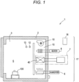
- An environmental test apparatus 1 includes a heat insulating chamber 3 covered with a heat insulating wall 2 as illustrated in FIG. 1 .
- a test chamber 5 is formed in a part of the heat insulating chamber 3.
- the test chamber 5 is a space in which a test target object 100 is installed.
- the environmental test apparatus 1 further includes a humidifier 6, a cooling device (cooling portion) 7, a heater (heating portion) 8, and a blower 10.
- the environmental test apparatus 1 has an air flow path 15 communicating with the test chamber 5, and the air flow path 15 is provided with the humidifier 6, the cooling device 7, the heater 8, and the blower 10.
- a temperature sensor (chamber internal temperature detection unit) 12 and a humidity sensor 13 are provided on an outlet side of the air flow path 15.
- an air conditioner 17 is configured by the members in the air flow path 15, the temperature sensor 12, and the humidity sensor 13.
- the air conditioner 17 is controlled by a control device (controller) 16.
- the environmental test apparatus 1 can create a desired temperature/humidity environment in the test chamber 5 by the air conditioner 17 controlled by the control device 16. That is, the control device 16 controls an inside of the test chamber 5 to a predetermined environment.
- the control device (controller) 16 is configured by, for example, a processor.
- the cooling device 7 adopted in the environmental test apparatus 1 according to the present embodiment includes a refrigeration circuit 18 as illustrated in FIG. 2 .
- the refrigeration circuit 18 of the cooling device (cooling portion) 7 will be described below.
- the cooling device 7 has a cascade cooling structure including a primary refrigeration circuit 20 and a secondary refrigeration circuit 21.
- the primary refrigeration circuit 20 is configured such that a refrigerant discharge port 32 of a high temperature side compressor 25, a high temperature side condenser 26, a high temperature side expansion portion 27, a primary flow path 30 of a cascade condenser 28, and a refrigerant suction port 33 of the high temperature side compressor 25 are sequentially connected in a ring.
- a phase-changing high temperature side refrigerant is enclosed in the primary refrigeration circuit 20 described above.
- the primary refrigeration circuit 20 implements a refrigerating cycle similar to a known one.
- the high temperature side expansion portion 27 is an expansion valve of which a degree of opening can be adjusted by an actuator such as a motor.
- the secondary refrigeration circuit 21 is configured such that a refrigerant discharge port 73 of a low temperature side compressor 35, a secondary flow path 37 of the cascade condenser 28, a low temperature side expansion portion 38, a low temperature side evaporator (cooler) 40, and a refrigerant suction port 75 of the low temperature side compressor 35 are sequentially connected in a ring.
- the cascade condenser 28 functions as a condenser for the secondary refrigeration circuit 21.
- the low temperature side evaporator (cooler) 40 is installed in the air flow path 15 as illustrated in FIG. 1 .
- the low temperature side expansion portion 38 is an expansion valve of which a degree of opening can be adjusted by an actuator such as a motor.
- a phase-changing low-temperature side refrigerant is enclosed in the secondary side refrigeration circuit 21 described above.
- the refrigerant enclosed in the secondary refrigeration circuit 21 can create a low temperature of -70°C, for example.
- the secondary side refrigeration circuit 21 implements a refrigerating cycle similar to a known one. Then, the refrigerant in the primary refrigeration circuit 20 is evaporated in the primary flow path 30 of the cascade condenser 28 of the primary refrigeration circuit 20 to lower a temperature of the cascade condenser 28 in the same manner as in a known cascade cooling structure. The low temperature generated at this time condenses the refrigerant passing through the cascade condenser (condenser) 28 of the secondary refrigeration circuit 21.
- the secondary refrigeration circuit 21 also has three rows of bypass flow paths 42, 43, and 45.
- the first bypass flow path 42 is a flow path branched from a portion between the cascade condenser (condenser) 28 and the low temperature side expansion portion 38 and connected to a portion between the low temperature side evaporator 40 and the refrigerant suction port 75 of the low temperature side compressor 35. That is, the first bypass flow path 42 is a flow path that connects a discharge side of the cascade condenser (condenser) 28 and a suction side of the low temperature side compressor 35.
- a first bypass expansion portion 51 is provided in the first bypass flow path 42.
- the first bypass expansion portion 51 is a control valve that has an actuator such as a motor and can freely change a degree of opening according to an electric signal. It is desirable that the first bypass expansion portion 51 can be fully closed.
- a temperature detection unit 82 is attached to the low temperature side compressor 35, and the control device 16 adjusts the degree of opening of the first bypass expansion portion 51 according to a temperature detected by the temperature detection unit 82. Specifically, the control device 16 increases the degree of opening of the first bypass expansion portion 51 when the temperature detected by the temperature detection unit 82 increases, and decreases the degree of opening of the first bypass expansion portion 51 when the temperature detected by the temperature detection unit 82 decreases.
- the first bypass expansion portion 51 is normally fully closed, and is opened when a temperature detected by the temperature detection unit 82 exceeds a certain threshold. As the detected temperature rises, a degree of opening of the first bypass expansion portion 51 increases.
- the second bypass flow path 43 is also a flow path branched from a portion between the cascade condenser (condenser) 28 and the low temperature side expansion portion 38 and connected to a portion between the low temperature side evaporator 40 and the refrigerant suction port 75 of the low temperature side compressor 35. That is, the second bypass flow path 43 is a flow path that connects the discharge side of the cascade condenser (condenser) 28 and the suction side of the low temperature side compressor 35.
- a second bypass expansion portion 52 is provided in the second bypass flow path 43.
- the second bypass expansion portion 52 is a so-called thermal expansion valve.
- the thermal expansion valve is also called a thermal automatic expansion valve or a heat sensing expansion valve, and includes a temperature sensing cylinder 55.
- the thermal expansion valve has a plunger inside, and a degree of opening of an orifice changes according to a temperature of the temperature sensing cylinder 55 and a temperature near an outlet of the second bypass expansion portion 52. That is, a charge medium is enclosed in the temperature sensing cylinder 55, and the charge medium expands and contracts according to the temperature of the temperature sensing cylinder 55.
- a pressure of the temperature sensing cylinder 55 is applied to the plunger via a flange or the like, and as a result, a force is applied to the plunger in the thermal expansion valve according to a detected temperature of the temperature sensing cylinder 55. Further, since a refrigerant pressure on an outlet side of the orifice is also applied to the plunger via the flange or the like, a force is applied to the plunger according to a refrigerant temperature on the outlet side of the orifice. Since the orifice stops when both are balanced, the second bypass expansion portion 52 is consequently controlled based on a temperature around the temperature sensing cylinder 55 and a temperature near the second bypass expansion portion 52. The second bypass expansion portion 52 changes the degree of opening thereof so that a difference between the temperature of the temperature sensing cylinder 55 and the temperature near the outlet of the second bypass expansion portion 52 becomes a predetermined temperature.
- the second bypass expansion portion 52 can also be fully closed.
- the second bypass expansion portion 52 is normally fully closed and opens when the detected temperature of the temperature sensing cylinder 55 exceeds a certain threshold. As the detected temperature rises, the degree of opening thereof increases.
- the temperature sensing cylinder 55 is arranged near the refrigerant suction port 75 of the low temperature side compressor 35, and the temperature sensing cylinder 55 senses a temperature of the refrigerant introduced into the low temperature side compressor 35. Therefore, a degree of opening of the second bypass expansion portion 52 is adjusted according to the temperature of the refrigerant introduced into the low temperature side compressor 35.
- the degree of opening of the second bypass expansion portion 52 increases, and when the detected temperature decreases, the degree of opening thereof decreases.
- branching portion 56 between the cascade condenser 28 and the low temperature side expansion portion 38, and the branching portion 56 is further divided into the first bypass flow path 42 and the second bypass flow path 43.
- a flow path where the first bypass flow path 42 and the second bypass flow path 43 join is connected to a flow path leading between the low temperature side evaporator 40 and the refrigerant suction port 75 of the low temperature side compressor 35.
- a flow path configuration of a bypass flow path is not limited to the configuration illustrated in FIG. 2 .
- first bypass flow path 42 may be connected to one confluence portion and the second bypass flow path 43 may be connected to another confluence portion.
- the first bypass flow path 42 and the second bypass flow path 43 can function as a refrigerant cooling portion for lowering a temperature of the low temperature side compressor 35.
- the third bypass flow path 45 is a flow path that branches from a portion between the cascade condenser 28 and the low temperature side expansion portion 38 and that reaches an intermediate cooling port 47 of the low temperature side compressor 35.
- a third bypass expansion portion 58 is provided in the third bypass flow path 45.
- the third bypass expansion portion 58 is a control valve that has an actuator such as a motor and can freely change the degree of opening according to an electric signal. It is desirable that the third bypass expansion portion 58 can be fully closed.
- the third bypass expansion portion 58 is not limited to a configuration having a function of adjusting the degree of opening, and may be a configuration that does not have the function of adjusting the degree of opening of the valve itself such as a combination of a capillary tube and a solenoid valve. In this case, a refrigerant flow rate is adjusted by controlling an opening and closing interval of the solenoid valve. As a result, the degree of opening of the third bypass expansion portion 58 is substantially adjusted.
- the refrigerant flowing through the third bypass flow path 45 is also in a liquid phase or a gas-liquid mixture state and has a sufficient cooling capacity.
- the low temperature side compressor 35 adopted in the present embodiment is an enclosed compressor, and has a compression mechanism (compression portion) 71, a motor 72, and an oil pump (not illustrated) built in a closed container 70 of the low temperature side compressor 35.
- Electric power is supplied to the motor 72 in the closed container 70 from an electric power supply portion (not illustrated), and the motor 72 rotates in the closed container 70.
- the compression mechanism 71 is connected to a rotating shaft of the motor 72, and rotation of the motor 72 drives the compression mechanism 71 in the closed container 70.
- a type of the compression mechanism 71 is not limited, and may be, for example, a reciprocating type, a rotary type, a scroll type, or the like.
- the high temperature side compressor 25 has a compression mechanism (compression portion), a motor, and an oil pump (not illustrated) built in a closed container of the high temperature side compressor 25.
- the refrigerant suction port 75, the refrigerant discharge port 73, and the intermediate cooling port 47 are opened in the closed container 70.
- the refrigerant suction port 75 is a conduit that communicates an inside and an outside of the closed container 70.
- the refrigerant discharge port 73 is a conduit connecting a discharge portion of the compression mechanism 71 and the outside.
- the intermediate cooling port 47 is a conduit that communicates the inside and the outside of the closed container 70 and opens near a contour portion of the compression mechanism 71.
- a refrigerant is introduced into the closed container 70 from the refrigerant suction port 75.
- the refrigerant diffuses in the closed container 70.
- the compression mechanism 71 is driven, sucks and compresses the refrigerant in the closed container 70, and discharges the refrigerant from the refrigerant discharge port 73.
- the refrigerant introduced from the third bypass flow path 45 is injected from the intermediate cooling port 47 to the compression mechanism 71 to cool the compression mechanism 71.
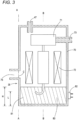
- An oil tank portion 81 is provided in the closed container 70 as illustrated in FIG. 3 , and a lubricating oil 80 is stored in the oil tank portion 81.
- the oil pump rotates to suck the lubricating oil 80 from the oil tank portion 81 and supply the lubricating oil 80 to each part in the closed container 70.
- the lubricating oil 80 supplied to each part returns to the oil tank portion 81. That is, the lubricating oil 80 circulates in the closed container 70.
- the low temperature side compressor 35 adopted in the present embodiment has the temperature detection unit 82 attached to an outer surface of the closed container 70.
- the temperature detection unit 82 is, for example, a thermistor or a thermocouple.
- An attachment position of the temperature detection unit 82 is equal to or lower than a height corresponding to the oil tank portion 81 in a height direction.
- the attachment position of the temperature detection unit 82 is equal to or lower than the height of the lubricating oil 80 stored in the closed container 70.
- the attachment position of the temperature detection unit 82 is at least at a position where at least a part of a temperature detection portion of the temperature detection unit 82 is equal to or lower than a height (hereinafter referred to as a maximum height H) of an oil level when the oil pump is stopped and most of the lubricating oil 80 is stored below.
- a more desirable height is the height in which the entirety of the temperature detection portion of the temperature detection unit 82 is equal to or lower than the maximum height H.
- the oil level lowers when the oil pump is driven, it is desirable that at least a part of the temperature detection portion of the temperature detection unit 82 is placed at a height equal to or lower than a height (hereinafter referred to as a minimum height L) of the oil level when the oil pump is driven.
- a more desirable height is the height in which the entirety of the temperature detection portion of the temperature detection unit 82 is equal to or lower than the minimum height L.
- the attachment position of the temperature detection unit 82 is desirably in an area opposite to the refrigerant suction port 75 in a circumferential direction.
- the attachment position of the temperature detection unit 82 in the circumferential direction is desirably in an area on a side opposite to the refrigerant suction port 75 with respect to an imaginary plane B that is parallel to the imaginary plane A and contains a center 76 of the closed container 70.
- the imaginary plane A is a plane that becomes a vertical plane when the low temperature side compressor 35 is installed on a horizontal floor surface, and includes the vertical plane C of the refrigerant suction port 75.
- the imaginary plane B is a plane that becomes a vertical plane when the low temperature side compressor 35 is installed on a horizontal floor surface, is parallel to the vertical plane C of the refrigerant suction port 75, and passes through the center 76 of the closed container 70.
- the attachment position of the temperature detection unit 82 in the circumferential direction is desirably in an area on the side opposite to the refrigerant suction port 75 with respect to the imaginary plane B.
- the attachment position of the temperature detection unit 82 is in an area from 3 o'clock to 9 o'clock.
- the area ranges from 90 degrees to 270 degrees with the position of the refrigerant suction port 75 as an origin.
- a more recommended range is a position between 5 o'clock to 7 o'clock. When converted to an angle, the position ranges from 150 degrees to 210 degrees with the position of the refrigerant suction port 75 as an origin.
- the lubricating oil 80 circulates in the closed container 70 as described above. Since the lubricating oil 80 also flows into the motor 72, a temperature of the lubricating oil 80 and a temperature of the motor 72 are highly correlated with each other. Therefore, the temperature of the lubricating oil 80 reflects the temperature of the motor 72.
- the temperature detection unit 82 is installed on the outer surface of the closed container 70 at a position equal to or lower than the height of the stored lubricating oil 80, so that the temperature detection unit 82 will detect the temperature of the lubricating oil 80 in the closed container 70. Since the temperature of the lubricating oil 80 reflects the temperature of the motor 72, the temperature detected by the temperature detection unit 82 has a high correlation with the temperature of the motor 72.
- the attachment position of the temperature detection unit 82 in the circumferential direction is an area on the side opposite to the refrigerant suction port 75. Therefore, the temperature detected by the temperature detection unit 82 is less likely to be affected by the refrigerant introduced into the closed container 70.
- the temperature of the refrigerant introduced into the closed container 70 is generally low. Therefore, when the temperature detection unit 82 is located near the refrigerant suction port 75, the temperature detection unit 82 may detect a low temperature due to the influence of the introduced refrigerant, and thus the correlation with the temperature of the motor 72 decreases.
- the temperature detection unit 82 since the attachment position of the temperature detection unit 82 is away from the refrigerant suction port 75, the temperature detection unit 82 is less likely to be affected by the refrigerant, and a temperature highly correlated with the temperature of the motor 72 can be detected.
- the cooling device 7 activates and drives the high temperature side compressor 25 of the primary refrigeration circuit 20 and the low temperature side compressor 35 of the secondary refrigeration circuit 21.
- the high temperature side compressor 25 compresses the refrigerant, and the high temperature side condenser 26 cools and condenses the refrigerant. Then, the liquefied refrigerant passes through a narrow gap of the high temperature side expansion portion 27 and enters the primary flow path 30 of the cascade condenser 28 to vaporize and lower the temperature of the cascade condenser 28. The refrigerant discharged from the primary flow path 30 of the cascade condenser 28 returns to the high temperature side compressor 25 and is compressed again.
- the low temperature side compressor 35 compresses the refrigerant, and the refrigerant is cooled and condensed in the secondary flow path 37 of the cascade condenser (condenser) 28. Then, the liquefied refrigerant passes through a narrow gap of the low temperature side expansion portion 38 and enters the low temperature side evaporator (cooler) 40 to vaporize and lower the temperature of the low temperature side evaporator (cooler) 40. The refrigerant discharged from the low temperature side evaporator (cooler) 40 returns to the low temperature side compressor 35 and is compressed again.
- the cooling device 7 is controlled by the control device 16 and operated so that a temperature inside the test chamber 5 is maintained at a set temperature.
- the low temperature side expansion portion 38 is controlled by the control device 16 so that the temperature inside the test chamber 5 approaches the set temperature. That is, the low temperature side expansion portion 38 is controlled so that the degree of opening increases when the difference between the temperature inside the test chamber 5 and the set temperature is large, and the degree of opening decreases when the temperature inside the test chamber 5 approaches the set temperature and a cooling load decreases.
- a refrigerant having a cooling capacity is supplied to the low temperature side compressor 35 from the first bypass flow path 42 and the second bypass flow path 43. Therefore, overload operation of the motor 72, burning of a coil, decrease in viscosity of the lubricating oil, and deterioration of the lubricating oil are suppressed.
- the temperature inside the low temperature side compressor 35 can become excessively high for the following two reasons.
- the environmental test apparatus 1 can create a high temperature environment and a low temperature environment in the test chamber 5.
- the control device 16 activates the cooling device 7 upon receiving an instruction to change the set temperature to a lower temperature.
- the temperature inside the low temperature side compressor 35 may become excessively high. That is, since the temperature inside the test chamber 5 is high, the liquefied refrigerant introduced into the low temperature side evaporator (cooler) 40 immediately vaporizes, and with the gas temperature of the refrigerant rising due to the heat of the test chamber 5, the refrigerant returns to the low temperature side compressor 35. Therefore, the temperature inside the low temperature side compressor 35 may become excessively high.
- a signal from the control device 16 throttles the degree of opening of the low temperature side expansion portion 38 to reduce an amount of the refrigerant supplied to the low temperature side evaporator (cooler) 40.
- the amount of cold heat for cooling the low temperature side compressor 35 is reduced.
- the motor 72 continues to rotate, the heat generated by the motor 72 is accumulated in the closed container 70 and the temperature inside the low temperature side compressor 35 rises.
- a low temperature state includes, for example, a range of -70°C to -40°C, - 40°C to -20°C, or -20°C to +30°C.
- the refrigerant returns to the low temperature side compressor 35 at a high temperature state.
- the temperature sensing cylinder 55 of the second bypass expansion portion 52 is arranged near the refrigerant suction port 75 of the low temperature side compressor 35, and the temperature sensing cylinder 55 senses the temperature of the refrigerant introduced into the low temperature side compressor 35.
- the temperature sensing cylinder 55 senses the temperature of the refrigerant introduced into the low temperature side compressor 35.
- the degree of opening of the low temperature side expansion portion 38 becomes small.
- the amount of the refrigerant returning from the low temperature side evaporator (cooler) 40 to the low temperature side compressor 35 is small, but the temperature of the returning refrigerant itself is low.
- the temperature detected by the temperature sensing cylinder 55 is low, and the second bypass expansion portion 52 is in a state where the degree of opening is small or remains closed. Therefore, the refrigerant cannot be expected to flow into the closed container 70 from the second bypass flow path 43.
- the refrigerant when the cooling load is small, the refrigerant is introduced into the closed container 70 from the first bypass flow path 42 instead of the second bypass flow path 43.
- the temperature detection unit 82 is attached to the outer surface of the closed container 70 and the temperature detection unit 82 substantially monitors the temperature of the lubricating oil 80 inside the closed container 70. Then, when the temperature detection unit 82 detects a high temperature, the control device 16 increases the degree of opening of the first bypass expansion portion 51. As a result, even when the temperature detected by the temperature sensing cylinder 55 is low and the second bypass flow path 43 does not open, the refrigerant having a cooling capacity flows through the first bypass flow path 42 and is introduced into the closed container 70 to suppress the temperature rise of the low temperature side compressor 35.
- the control device 16 controls the degree of opening of the first bypass expansion portion 51 according to the detection value of the temperature detection unit 82 when the inside of the test chamber 5 is in a stable state.
- the stable state includes a state in which the temperature inside the test chamber 5 reaches the set temperature or a predetermined allowable range of the set temperature.
- the stable state includes a state in which an output value of the heater 8 or an amount of change thereof calculated by the control device 16 is within a predetermined range, a state in which a cooling output value or the amount of change thereof calculated by the control device 16 is within a predetermined range, and a state in which the degree of opening of the low temperature side expansion portion 38 or the amount of change thereof calculated by the control device 16 is within a predetermined range.
- the second bypass flow path 43 opens to suppress the temperature rise of the low temperature side compressor 35.
- the cooling device 7 of the present embodiment opens the first bypass flow path 42 and suppresses the temperature rise of the low temperature side compressor 35 when the amount of the returning refrigerant is small, such as when the cooling load is small.
- the environmental test apparatus suppresses the excessive temperature rise of the low temperature side compressor 35 in any situation of an assumed use state, and thus the overload operation of the motor 72, burning of the coil, decrease in the viscosity of the lubricating oil, and deterioration of the lubricating oil are suppressed.
- the environmental test apparatus 1 since the environmental test apparatus 1 according to the present embodiment has the third bypass flow path 45 and the refrigerant is supplied from the third bypass flow path 45 to the intermediate cooling port 47 of the low temperature side compressor 35, the inside of the closed container 70 is also cooled by the refrigerant supplied from the intermediate cooling port 47.
- the third bypass expansion portion 58 of the third bypass flow path 45 substantially increases the degree of opening when the load on the motor 72 increases.
- the environmental test apparatus 1 illustrated in FIG. 1 is merely an example of the present invention, and the layout and the presence or absence of equipment are not limited.
- the air conditioner 17 may be on a lower side of the test chamber 5.
- the humidifier 6 and the humidity sensor 13 may be omitted if the purpose is solely to create a temperature environment.
- the embodiment described above is an environmental test apparatus mainly used for exposing a test target object to a high temperature environment or a low temperature environment.
- the present invention is not limited to this type of environmental test apparatus, and can also be applied to an environmental test apparatus called a thermal shock test apparatus or a thermal cycle test apparatus.
- an electronic control valve that can freely change the degree of opening by an electric signal is adopted as the first flow rate control portion.
- the present invention does not limit the first flow rate control portion to an electronic control valve.
- a combination of a throttle member such as a capillary tube and an on-off valve such as a solenoid valve may be used as the first flow rate control portion.
- a configuration is conceivable in which an opening and closing time interval of the solenoid valve is controlled to control a substantial degree of opening.
- the same can be applied to the second flow rate control portion, and a combination of a throttle member such as a capillary tube and an on-off valve such as a solenoid valve, or a sub-bypass flow path in which a plurality of throttle members such as capillary tubes are connected in parallel may be used as the second flow rate control portion.
- the second bypass flow path 43 and the third bypass flow path 45 are provided in addition to the first bypass flow path 42.
- the second bypass flow path 43 and the third bypass flow path 45 are not essential, and either the second bypass flow path 43 or the third bypass flow path 45 may be omitted. Also, both the second bypass flow path 43 and the third bypass flow path 45 may be omitted.
- control device 16 controls the degree of opening of the first bypass expansion portion 51 according to a detection value of the temperature detection unit 82 when the inside of the test chamber 5 is in a stable state.
- a configuration may be adopted in which a determination portion for determining whether the inside of the test chamber 5 is in a stable state is provided, and the degree of opening of the first bypass expansion portion 51 is controlled according to the detection value of the temperature detection unit 82 on the condition that the determination portion determines that the state is stable.
- the first bypass expansion portion 51 may be operated without providing the determination portion.
- the attachment position of the temperature detection unit 82 is equal to or lower than the height position corresponding to the oil tank portion 81 in the height direction and is in the area on a side opposite to the refrigerant suction port 75 with respect to the imaginary plane B in the circumferential direction.
- the present invention does not limit the attachment position of the temperature detection unit 82 to this position, and the temperature detection unit 82 may be located at any position.
- the environmental test apparatus 1 described above adopts the cooling device (cooling portion) 7 having a cascade cooling structure.
- the present invention is not limited to this configuration, and may adopt a cooling device (cooling portion) having a single cooling structure.
- a typical cooling device having a single cooling structure has one compressor, one condenser, one expansion portion, and one evaporator, in which a phase-changing refrigerant is circulated.
- the cooling device having the single cooling structure adopting the present invention has a first bypass flow path connecting a discharge side of a condenser and a suction side of a compressor, and the first bypass flow path is provided with a first flow rate control portion.
- a temperature measurement portion is provided in the one compressor, and a substantial degree of opening of the first flow rate control portion is controlled according to a detection value of the temperature measurement portion.
- the cooling device having the single cooling structure adopting the present invention preferably includes a second bypass flow path and a third bypass flow path in addition to the first bypass flow path.
- a position where the temperature measurement portion is attached to the compressor is preferably the same position as in the case of the low temperature side compressor 35 of the cooling device (cooling portion) 7 having the cascade cooling structure of the present embodiment.
Landscapes
- Engineering & Computer Science (AREA)
- Physics & Mathematics (AREA)
- Mechanical Engineering (AREA)
- Thermal Sciences (AREA)
- General Engineering & Computer Science (AREA)
- General Physics & Mathematics (AREA)
- Life Sciences & Earth Sciences (AREA)
- Environmental Sciences (AREA)
- Ecology (AREA)
- Environmental & Geological Engineering (AREA)
- Biodiversity & Conservation Biology (AREA)
- Health & Medical Sciences (AREA)
- Chemical & Material Sciences (AREA)
- Analytical Chemistry (AREA)
- Biochemistry (AREA)
- General Health & Medical Sciences (AREA)
- Immunology (AREA)
- Pathology (AREA)
- Testing Resistance To Weather, Investigating Materials By Mechanical Methods (AREA)
- Compressor (AREA)
Applications Claiming Priority (1)
| Application Number | Priority Date | Filing Date | Title |
|---|---|---|---|
| JP2022103245A JP7708716B2 (ja) | 2022-06-28 | 2022-06-28 | 環境試験装置 |
Publications (1)
| Publication Number | Publication Date |
|---|---|
| EP4300007A1 true EP4300007A1 (de) | 2024-01-03 |
Family
ID=87047522
Family Applications (1)
| Application Number | Title | Priority Date | Filing Date |
|---|---|---|---|
| EP23181572.1A Pending EP4300007A1 (de) | 2022-06-28 | 2023-06-26 | Umwelttestvorrichtung |
Country Status (4)
| Country | Link |
|---|---|
| US (1) | US20230417632A1 (de) |
| EP (1) | EP4300007A1 (de) |
| JP (1) | JP7708716B2 (de) |
| CN (1) | CN117309733A (de) |
Citations (5)
| Publication number | Priority date | Publication date | Assignee | Title |
|---|---|---|---|---|
| DE818648C (de) * | 1945-03-01 | 1951-10-25 | Gen Motors Corp | Kompressionskaeltemaschine |
| EP0344397B1 (de) * | 1988-05-30 | 1993-03-17 | Heraeus-Vötsch GmbH | Klimaprüfkammer |
| KR20060115821A (ko) * | 2005-05-06 | 2006-11-10 | 엘지전자 주식회사 | 공기 조화기의 층분리 방지 장치 |
| JP2014066593A (ja) | 2012-09-26 | 2014-04-17 | Hitachi Appliances Inc | 恒温恒湿装置 |
| US11162714B2 (en) * | 2018-06-19 | 2021-11-02 | Weiss Technik Gmbh | Test chamber and method |
Family Cites Families (5)
| Publication number | Priority date | Publication date | Assignee | Title |
|---|---|---|---|---|
| JP3861913B1 (ja) * | 2004-09-02 | 2006-12-27 | ダイキン工業株式会社 | 冷凍装置 |
| CN106030219B (zh) * | 2014-02-18 | 2018-11-09 | 三菱电机株式会社 | 空气调节装置 |
| IL260376A (en) * | 2018-07-02 | 2019-01-31 | KALISHER Victor Shalom | Methods and systems for a rapid-fire defense system controlled by a fixed and liquid-cooled radar |
| WO2020049844A1 (ja) * | 2018-09-06 | 2020-03-12 | 日立ジョンソンコントロールズ空調株式会社 | 圧縮機、及び、これを備える冷凍サイクル装置 |
| JP6650062B2 (ja) * | 2019-02-20 | 2020-02-19 | エスペック株式会社 | 環境試験装置 |
-
2022
- 2022-06-28 JP JP2022103245A patent/JP7708716B2/ja active Active
-
2023
- 2023-06-22 US US18/339,572 patent/US20230417632A1/en active Pending
- 2023-06-26 EP EP23181572.1A patent/EP4300007A1/de active Pending
- 2023-06-27 CN CN202310769892.0A patent/CN117309733A/zh active Pending
Patent Citations (5)
| Publication number | Priority date | Publication date | Assignee | Title |
|---|---|---|---|---|
| DE818648C (de) * | 1945-03-01 | 1951-10-25 | Gen Motors Corp | Kompressionskaeltemaschine |
| EP0344397B1 (de) * | 1988-05-30 | 1993-03-17 | Heraeus-Vötsch GmbH | Klimaprüfkammer |
| KR20060115821A (ko) * | 2005-05-06 | 2006-11-10 | 엘지전자 주식회사 | 공기 조화기의 층분리 방지 장치 |
| JP2014066593A (ja) | 2012-09-26 | 2014-04-17 | Hitachi Appliances Inc | 恒温恒湿装置 |
| US11162714B2 (en) * | 2018-06-19 | 2021-11-02 | Weiss Technik Gmbh | Test chamber and method |
Also Published As
| Publication number | Publication date |
|---|---|
| CN117309733A (zh) | 2023-12-29 |
| US20230417632A1 (en) | 2023-12-28 |
| JP2024003898A (ja) | 2024-01-16 |
| JP7708716B2 (ja) | 2025-07-15 |
Similar Documents
| Publication | Publication Date | Title |
|---|---|---|
| KR101439874B1 (ko) | 유체 주입부를 갖는 응축 유닛 | |
| CA2140192C (en) | Combined oil return and compressor discharge temperature limitation regarding flooded economizer heat exchanger | |
| US5410889A (en) | Methods and apparatus for operating a refrigeration system | |
| CA2140179C (en) | Two mop expansion valves, one pressure setting for heating mode and one for cooling mode | |
| US11391504B2 (en) | Refrigerator | |
| EP1707900A1 (de) | Kühlvorrichtung | |
| KR101602741B1 (ko) | 항온액 순환 장치 및 그 운전 방법 | |
| US11073313B2 (en) | Method of managing compressor start for transport refrigeration system | |
| JP2008267787A (ja) | 冷凍装置 | |
| SG183387A1 (en) | Refrigerant distribution apparatus and methods for transport refrigeration system | |
| US6779355B2 (en) | Refrigeration device | |
| WO2019189315A1 (ja) | 圧縮機、冷凍サイクル装置 | |
| US20170074551A1 (en) | Refrigeration apparatus | |
| EP4300007A1 (de) | Umwelttestvorrichtung | |
| US20220186988A1 (en) | Refrigeration apparatus | |
| JP6153439B2 (ja) | 環境試験装置 | |
| JPH04251164A (ja) | 冷凍サイクル装置 | |
| JPH0650877A (ja) | 環境試験装置 | |
| JPH085172A (ja) | 冷凍冷蔵庫の冷却装置 | |
| JP2024165668A (ja) | 冷凍装置及び環境試験装置 | |
| EP3872419A1 (de) | Kühlvorrichtung | |
| JP2024043621A (ja) | 熱源ユニット、および冷凍装置 | |
| JP2024045940A (ja) | 熱源ユニット、熱源システム、および冷凍装置 | |
| CN113959022A (zh) | 空调机组及其控制方法 | |
| KR20030086733A (ko) | 냉장고의 온도조절 장치 및 그 방법 |
Legal Events
| Date | Code | Title | Description |
|---|---|---|---|
| PUAI | Public reference made under article 153(3) epc to a published international application that has entered the european phase |
Free format text: ORIGINAL CODE: 0009012 |
|
| STAA | Information on the status of an ep patent application or granted ep patent |
Free format text: STATUS: THE APPLICATION HAS BEEN PUBLISHED |
|
| AK | Designated contracting states |
Kind code of ref document: A1 Designated state(s): AL AT BE BG CH CY CZ DE DK EE ES FI FR GB GR HR HU IE IS IT LI LT LU LV MC ME MK MT NL NO PL PT RO RS SE SI SK SM TR |
|
| STAA | Information on the status of an ep patent application or granted ep patent |
Free format text: STATUS: REQUEST FOR EXAMINATION WAS MADE |
|
| 17P | Request for examination filed |
Effective date: 20240701 |
|
| RBV | Designated contracting states (corrected) |
Designated state(s): AL AT BE BG CH CY CZ DE DK EE ES FI FR GB GR HR HU IE IS IT LI LT LU LV MC ME MK MT NL NO PL PT RO RS SE SI SK SM TR |
|
| STAA | Information on the status of an ep patent application or granted ep patent |
Free format text: STATUS: EXAMINATION IS IN PROGRESS |
|
| 17Q | First examination report despatched |
Effective date: 20250801 |