EP4299873B1 - Einlassrohr, gesteinsbohrvorrichtung und verfahren zur probenahme - Google Patents
Einlassrohr, gesteinsbohrvorrichtung und verfahren zur probenahme Download PDFInfo
- Publication number
- EP4299873B1 EP4299873B1 EP22182452.7A EP22182452A EP4299873B1 EP 4299873 B1 EP4299873 B1 EP 4299873B1 EP 22182452 A EP22182452 A EP 22182452A EP 4299873 B1 EP4299873 B1 EP 4299873B1
- Authority
- EP
- European Patent Office
- Prior art keywords
- inlet tube
- homogenizing
- drilling
- flow
- section
- Prior art date
- Legal status (The legal status is an assumption and is not a legal conclusion. Google has not performed a legal analysis and makes no representation as to the accuracy of the status listed.)
- Active
Links
Images

Classifications
-
- E—FIXED CONSTRUCTIONS
- E21—EARTH OR ROCK DRILLING; MINING
- E21B—EARTH OR ROCK DRILLING; OBTAINING OIL, GAS, WATER, SOLUBLE OR MELTABLE MATERIALS OR A SLURRY OF MINERALS FROM WELLS
- E21B7/00—Special methods or apparatus for drilling
- E21B7/02—Drilling rigs characterised by means for land transport with their own drive, e.g. skid mounting or wheel mounting
-
- E—FIXED CONSTRUCTIONS
- E21—EARTH OR ROCK DRILLING; MINING
- E21B—EARTH OR ROCK DRILLING; OBTAINING OIL, GAS, WATER, SOLUBLE OR MELTABLE MATERIALS OR A SLURRY OF MINERALS FROM WELLS
- E21B21/00—Methods or apparatus for flushing boreholes, e.g. by use of exhaust air from motor
- E21B21/06—Arrangements for treating drilling fluids outside the borehole
- E21B21/07—Arrangements for treating drilling fluids outside the borehole for treating dust-laden gaseous fluids
-
- B—PERFORMING OPERATIONS; TRANSPORTING
- B01—PHYSICAL OR CHEMICAL PROCESSES OR APPARATUS IN GENERAL
- B01F—MIXING, e.g. DISSOLVING, EMULSIFYING OR DISPERSING
- B01F25/00—Flow mixers; Mixers for falling materials, e.g. solid particles
- B01F25/40—Static mixers
- B01F25/42—Static mixers in which the mixing is affected by moving the components jointly in changing directions, e.g. in tubes provided with baffles or obstructions
- B01F25/43—Mixing tubes, e.g. wherein the material is moved in a radial or partly reversed direction
- B01F25/431—Straight mixing tubes with baffles or obstructions that do not cause substantial pressure drop; Baffles therefor
- B01F25/4311—Straight mixing tubes with baffles or obstructions that do not cause substantial pressure drop; Baffles therefor the baffles being adjustable
-
- B—PERFORMING OPERATIONS; TRANSPORTING
- B01—PHYSICAL OR CHEMICAL PROCESSES OR APPARATUS IN GENERAL
- B01F—MIXING, e.g. DISSOLVING, EMULSIFYING OR DISPERSING
- B01F25/00—Flow mixers; Mixers for falling materials, e.g. solid particles
- B01F25/40—Static mixers
- B01F25/42—Static mixers in which the mixing is affected by moving the components jointly in changing directions, e.g. in tubes provided with baffles or obstructions
- B01F25/43—Mixing tubes, e.g. wherein the material is moved in a radial or partly reversed direction
- B01F25/431—Straight mixing tubes with baffles or obstructions that do not cause substantial pressure drop; Baffles therefor
- B01F25/43197—Straight mixing tubes with baffles or obstructions that do not cause substantial pressure drop; Baffles therefor characterised by the mounting of the baffles or obstructions
- B01F25/431971—Mounted on the wall
-
- E—FIXED CONSTRUCTIONS
- E21—EARTH OR ROCK DRILLING; MINING
- E21B—EARTH OR ROCK DRILLING; OBTAINING OIL, GAS, WATER, SOLUBLE OR MELTABLE MATERIALS OR A SLURRY OF MINERALS FROM WELLS
- E21B21/00—Methods or apparatus for flushing boreholes, e.g. by use of exhaust air from motor
- E21B21/01—Arrangements for handling drilling fluids or cuttings outside the borehole, e.g. mud boxes
- E21B21/011—Dust eliminating or dust removing while drilling
-
- E—FIXED CONSTRUCTIONS
- E21—EARTH OR ROCK DRILLING; MINING
- E21B—EARTH OR ROCK DRILLING; OBTAINING OIL, GAS, WATER, SOLUBLE OR MELTABLE MATERIALS OR A SLURRY OF MINERALS FROM WELLS
- E21B21/00—Methods or apparatus for flushing boreholes, e.g. by use of exhaust air from motor
- E21B21/01—Arrangements for handling drilling fluids or cuttings outside the borehole, e.g. mud boxes
- E21B21/015—Means engaging the bore entrance, e.g. hoods for collecting dust
-
- E—FIXED CONSTRUCTIONS
- E21—EARTH OR ROCK DRILLING; MINING
- E21B—EARTH OR ROCK DRILLING; OBTAINING OIL, GAS, WATER, SOLUBLE OR MELTABLE MATERIALS OR A SLURRY OF MINERALS FROM WELLS
- E21B21/00—Methods or apparatus for flushing boreholes, e.g. by use of exhaust air from motor
- E21B21/06—Arrangements for treating drilling fluids outside the borehole
- E21B21/062—Arrangements for treating drilling fluids outside the borehole by mixing components
-
- E—FIXED CONSTRUCTIONS
- E21—EARTH OR ROCK DRILLING; MINING
- E21B—EARTH OR ROCK DRILLING; OBTAINING OIL, GAS, WATER, SOLUBLE OR MELTABLE MATERIALS OR A SLURRY OF MINERALS FROM WELLS
- E21B49/00—Testing the nature of borehole walls; Formation testing; Methods or apparatus for obtaining samples of soil or well fluids, specially adapted to earth drilling or wells
- E21B49/003—Testing the nature of borehole walls; Formation testing; Methods or apparatus for obtaining samples of soil or well fluids, specially adapted to earth drilling or wells by analysing drilling variables or conditions
-
- E—FIXED CONSTRUCTIONS
- E21—EARTH OR ROCK DRILLING; MINING
- E21B—EARTH OR ROCK DRILLING; OBTAINING OIL, GAS, WATER, SOLUBLE OR MELTABLE MATERIALS OR A SLURRY OF MINERALS FROM WELLS
- E21B49/00—Testing the nature of borehole walls; Formation testing; Methods or apparatus for obtaining samples of soil or well fluids, specially adapted to earth drilling or wells
- E21B49/08—Obtaining fluid samples or testing fluids, in boreholes or wells
- E21B49/086—Withdrawing samples at the surface
Definitions
- the invention relates to an inlet tube of a sample taking arrangement in a rock drilling rig.
- the inlet tube directs flow of drilling cuttings and air to a sampling point wherein samples are taken for analyzing properties of rock being drilled.
- the invention further relates to a rock drilling rig and to a method of taking samples of drilling cuttings during rock drilling.
- An object of the invention is to provide a novel and improved inlet tube, rock drilling rig and method for taking samples during a drilling process.
- the inlet tube according to the invention is characterized by the characterizing features of the first independent apparatus claim.
- the rock drilling rig according to the invention is characterized by the characterizing features of the second independent apparatus claim.
- the method according to the invention is characterized by the characterizing features of the independent method claim.
- a dust collecting system of a rock drilling rig comprises a sample taking arrangement for taking samples out of flow comprising air and drilling cuttings.
- the sampling is executed at a sampling point by means of a sampling device, for example.
- An inner cross-section of the inlet tube comprises a homogenizing section provided with one or more homogenizing elements for forming a physical point of discontinuity wherein shape and dimensions of the inner cross-section differ locally from sections prior and after the homogenizing section.
- the homogenizing element generates disturbances in the flow and can homogenize particle distribution of the drilling cuttings in the flow at the section after the homogenizing section and prior to the sampling point.
- the homogenizing element is actively controllable whereby it can selectively provide the homogenizing section with the physical point of discontinuity and the desired particle spreading.
- the flow inside the inlet tube is disturbed by the physical and dynamic homogenizing element so that the solid drilling cutting particles with different sizes are spread more evenly at the section following the homogenizing section.
- the homogenizing element causes a sudden change in flow geometry and dimensions inside the inlet tube when needed and this way particle distribution in the flow is changed.
- An advantage of the disclosed solution is that representative samples of the drilling cuttings inside the inlet tube can be taken when the particles with different size are spread more evenly inside the inlet tube. This way quality of samples can be improved and more accurate and reliable analyzing results can be achieved.
- a further advantage is that the disclosed solution is relatively simple, and inexpensive.
- the solution is also durable, since when the homogenizing element is in its basic position and is not active, there are no protruding physical elements subjected to wearing inside the inlet tube. Further, when the homogenizing element is not under operation, there are no physical elements which would narrow cross-sectional flow area of the inlet tube at the homogenizing section.
- the disclosed inlet tube can also be retrofitted easily to the existing dust collecting systems.
- operation of the homogenizing element can be controlled by means of a control unit.
- the homogenizing element may be normally inoperable and can be selectively connected to operative state. Thus, when being inoperable, there is no discontinuity inside the inlet tube and when connected operative, the discontinuity is formed.
- An advantage of the controllable element is that it does not cause throttling to the flow when the spreading particle effect is not needed.
- the control unit may activate the homogenizing element when taking samples and then return to unoperated state.
- magnitude of the caused discontinuity of the homogenizing element may be controlled under control of the control unit.
- the shape, dimensions, or both can be varied. This way the homogenizing element can be adjusted to different flows and situations.
- controllable homogenizing element is controlled by one or more actuators which are controlled by means of the control unit.
- the actuators may be pneumatic, hydraulic, or electrical. Further, the actuators may be motors, linear motors, or cylinders, for example.
- number of the homogenizing elements is one.
- one single discontinuity causing element may be sufficient to cause needed particle spreading in the flow.
- the spreading effect can be increased and there are several control possibilities for adjusting the solution to different flow situations, for example.
- shape and dimensions of the homogenizing element are dependent on structure and dimensions of the inlet tube, for example, and can therefore be designed case by case.
- Flow control simulation and modelling programs can be utilized for determining the shapes and dimensions of the homogenizing elements.
- the inlet tube comprises a bend and the homogenizing section is located at the bend.
- the homogenizing element is located at the bend of the inlet tube. It has been noted in experiments that the effect of the homogenizing element is intensified when it is located at the bend.
- the use of the bend is also beneficial because there is typically a need to direct tubes and hoses of the dust collection in angular positions and especially at areas close to separators and other devices. In bends the solid particles are often moved in the flow towards an outer side of the bend, whereby the homogenizing element can compensate this undesirable phenomena caused by inertia of the particles.
- the bend may be 90°, or substantially 90°.
- the bend may also be any bend between 45 - 135°.
- the inlet tube may in some cases be without any bend whereby the homogenizing section and the homogenizing element are located at a straight section.
- the inlet tube comprises a bend with an inner curve and an outer curve and wherein the at least one homogenizing element is provided on the outer curve of the bend.
- the particle spreading occurs at the outer curve of the bend which is the most critical point where the solid particles tend to concentrate in the flow. Directing the particles at the outer curve side has been found to be effective.
- the at least one homogenizing element is located only on the outer curve side of the bend.
- the homogenizing element is a selectively expandable element.
- the homogenizing element is a bellows. Then the homogenizing element can be activated by directing pressure fluid flow inside it and when the pressure fluid flow is discharged, the homogenizing element returns from an active mode to an idle mode.
- the expandable element is an integrated part of a wall structure of the inlet tube.
- the expandable element is a separate element mounted on an inner surface of a wall structure of the inlet tube.
- the homogenizing element is alternatively a mechanically movable element which can be selectively moved in transverse direction relative to direction of the flow so that it can serve as a particle spreading element for the flow.
- a mechanically movable element which can be selectively moved in transverse direction relative to direction of the flow so that it can serve as a particle spreading element for the flow.
- the mechanically movable element may comprise one or more shaped pieces which can be moved by means of one or more cylinders or motors, for example.
- the inlet tube is made of resilient material and comprises one or more actuators at the homogenizing section for directing external force on an outer surface side of the inlet tube for selectively causing reversible deformation for the structure of the inlet tube at the homogenizing section. Then material of a wall of the inlet tube protrudes inwards providing the inlet tube with an inner bulge which serves as the mentioned homogenizing element. In other words, shape of shell or envelope of the inlet tube is reversibly deformed for producing the desired particle spreading protrusion inside the inlet tube.
- the inlet tube itself forms the homogenizing element and no separate elements are required. This way, the solution is simple, inexpensive, and durable.
- the inlet tube is made of rubber, or rubber-like resilient material. Then the resilient inlet tube can be pressed locally and temporarily inwards and when the pressing is released, the inlet tube resumes its original shape and dimensions.
- the actuator for pressing the inlet tube may be a linear actuator, such as a pressure medium cylinder, or an electronic linear motor.
- the actuator may be provided with a pushing element by means of which the force is directed to the outer surface of the inlet tube.
- the pushing element may be a pin longitudinal direction of which is directed towards the outer surface of the inlet tube. Then a round end of the pin is directed to the wall of inlet tube.
- the pushing element may be a pin with round cross sectional shape and its outer surface is transverse to the inlet tube and is pushed against the outer surface of the inlet tube. Then a bulge is formed. In these two alternatives the pins form two different kind of bulges inside the inlet tube.
- the actuator has fixed movement length whereby the bulge formed inside the inlet tube has substantially constant shape and dimensions.
- movement length and/or force generated by the actuator can be adjusted whereby the shape and dimensions of the bulge inside the inlet tube may be adjusted.
- the disclosed solution relates to a rock drilling rig comprising: a movable carrier; at least one drilling boom mounted on the carrier and comprising a rock drilling unit provided with a rock drilling machine; a dust collecting system for removing drilling cuttings from an opening of a drilled hole, wherein the dust collecting system is provided with a suction unit, dust collecting tubing, and at least one separator for separating solid particles from flow containing air and the drilling cuttings; and at least one sampling point for taking samples of the flow. Further, the sampling point is located prior to the separator so that the flow is still unseparated at the sampling point, and there is an inlet tube with an actively controllable homogenizing element in the dust collecting system preceding the sampling point.
- the inlet tube is in accordance with the features and embodiments disclosed in this document.
- the sampling point is located before any separation measures for the flow have been executed.
- An advantage of this is that the flow, where from the samples are taken, comprises all possible particles since nothing has been removed from the flow.
- the dust collecting system comprises a first separator for separating coarse solid particles from the flow and a second separator for separating fine solid particles from the flow.
- the first separator may be located on the drilling boom whereas the second separator may be located on the carrier.
- the first separator may be a cyclone.
- the inlet tube and the sampling point are located just before the first separator.
- the disclosed solution can be implemented in different kind of drilling techniques and purposes including for example production drilling and exploration drilling.
- the solution is suitable to be used in connection with top hammer drilling, DTH drilling and rotary drilling, for example.
- the disclosed solution relates to a method of sampling in a rock drilling rig, wherein the method comprises: drilling drill holes to a rock surface; collecting produced drilling cuttings from an opening of the drill holes during the drilling by means of a dust collecting system; taking samples of flow containing air and drilling cuttings at a sampling point of the dust collecting system during the drilling; and providing the dust collecting system with an inlet tube before the sampling point.
- the method further comprises changing actively cross-sectional inner shape and dimensions of the inlet tube locally for spreading drilling cutting particles in the flow evenly across the inner cross-section of the inlet tube whereby the samples are taken downstream the mentioned particle spreading.
- the method comprises activating controlled sudden changes in flow geometry and dimensions inside the inlet tube for the duration of the sampling process.
- the method further comprises pressing transversally a reversible deform to a resilient wall structure of the inlet tube at the homogenizing section for changing cross-sectional inner shape and dimensions of the inlet tube locally by means of an inner bulge formed in response of the pressing.
- the method further comprises controlling the change of the cross-sectional inner shape and dimensions of the inlet tube under control of a control unit.
- Figure 1 discloses a rock drilling rig 1 comprising a movable carrier 2 and a drilling boom 3 mounted on the carrier 2.
- the drilling boom 3 is provided with a rock drilling unit 4 for drilling drill holes 5 to a rock surface.
- the rock drilling unit 4 comprises a rock drilling machine 6 which may be arranged movably on a feed beam 7.
- the rock drilling machine 6 may comprise an impact device and a rotating device, or alternatively it may be a rotary drilling machine and may be without any impact device.
- a drilling tool 8 is connected to the rock drilling machine 6 and the drilling tool 8 may comprise one or more drill tubes and a drill bit 9 at its free end. During the drilling rock material is broken and drilling cuttings are formed in the drill hole 5. The drilling cuttings needs to be flushed away from the drill hole 5.
- pressurized air is produced by means of a compressor CO and the pressurized air is directed via the drilling tool 8 to a bottom of the drill hole 5 whereby drilling cuttings are flushed away.
- the drilling cuttings can be collected by a means of a dust collecting system 10 comprising a suction unit 11 for producing negative pressure so that the drilling cuttings can be sucked from a drill hole opening 12 via dust collecting tubes 13.
- a main purpose of the dust collecting system 10 is to transfer the drilling cuttings away from the drill hole opening 12 so that visibility to the drilled target is good and no difficulties occur for the drilling process due to large amount of the material removed from the drill hole 5.
- the dust collecting system 5 may also comprise one or more separators for processing the collected material.
- the first separator 15 may be mounted on the drilling boom 3 and it may comprise a cyclone, for example.
- the second separator 16 may be mounted on the carrier 2 in connection with the suction unit 11, for example.
- a sampling device 17 for taking samples out of flow of drilling cuttings and air in the system is arranged before the first separator 15 whereby it is located prior to any separation phase. Further, an inlet tube 18 is located before the sampling device 17. The inlet tube 18 conveys the flow to a sampling point of the sampling device 17. The inlet tube 18 comprises a homogenizing element for spreading the drilling cuttings in the flow so that proper samples can be taken from the flow. Operation and structure of the homogenizing element is as it is disclosed in this document.
- the rock drilling rig 1 may comprise one or more control units CU for controlling the operation and actuators.
- the control unit CU may control the sampling device 17 and the homogenizing element of the inlet tube 18, for example. Some control situations and principles are disclosed above in this document.
- the control unit may comprise a processor for executing an input computer program product or algorithm, and it may be provided with sensing data and input control parameters.
- Figure 2 discloses a dust collecting system 10 for sucking drilling cuttings from a drill hole opening 12.
- the system 10 comprises dust collecting tubes 13 for transferring the collected flow via an inlet tube 18 to a sampling device 17 and only then to a separator 15.
- a sampling point SP is located between the inlet tube 18 and the separator 15.
- the inlet tube 18 is provided with a homogenizer for ensuring proper particle distribution in the flow.
- Samples SA are taken from the flow in accordance with a planned sampling schedule or procedure.
- the samples SA can be analyzed A either online 21 or later on in a laboratory 22.
- Figure 3 discloses that an inlet tube 18 comprises a homogenizing section 23 wherein an inner cross-section of the inlet tube 18 comprises one or more homogenizing elements 24 forming a physical point of discontinuity wherein shape and dimensions of the inner cross-section differ locally from sections prior and after the homogenizing section 23.
- the homogenizing section 23 may be located at a bend 25 or at a straight part 26 of the inlet tube 18.
- the homogenizing element 24 is dynamically controlled 27 and can generate disturbance in the flow when needed.
- the homogenizing element 24 may have different configurations. It may be based on deformation 28 of shape of the inlet tube 18. Alternatively, it may comprise an expandable element 29, or a movable element arranged on inner surface of the inlet tube 18.
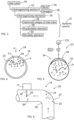
- Figure 4 discloses that external force F can be directed towards structure of an inlet tube 18 and cause thereby inwardly protruding bulge 31 at a homogenizing section 23.
- the produced deformation 28 can serve as a homogenizing element.
- the external force F may be transmitted mechanically or by any other suitable means to cause the desired deformation on wall of the inlet tube 18.
- the bulge 31 or protruding deformation can direct solid particles towards a free flow passage area inside the inlet tube 18.
- the force F is controlled by means of a control unit, for example.
- Figure 5 discloses a basic principle of an expandable element 29 which is connectable to a pressure circuit, in this example to a pneumatic circuit wherein a compressor CO generates pressurized air and wherein a valve V and a control unit CU can control operation of the expandable element 29.
- Arrows indicate expansion of the expandable element 29.
- the expandable element 29 serves as a homogenizing element 24 and it may be either integrated as a part of the inlet tube 23, or it may be a separate element mounted on an inner surface of the inlet tube 23, for example.
- Figure 6 discloses an inlet tube 18 provided with a bend 25 comprising an inner curve 26 and an outer curve 27.
- a homogenizing section 23 is located at the bend 25 and an actively controllable dynamic homogenizing element 24 is located on a side of the outer curve 27.
- the sampling device 17 may comprise a tube or sampling pipe 28 which is partly insertable inside the flow channel, and which is provided with an opening 29 through which material to be collected passes during the sampling.
- the samples taken can be stored in receptacles or bags, for example.
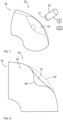
- Figure 7 discloses that an inlet tube 18 may be made of resilient material and can be reversible deformed by pushing its outer surface by means of a plunger or pushing element 30 provided with a rounded end 31. Then the deformed wall structure of the inlet tube 18 forms a homogenizing element 24 i.e., a bulge inside a homogenizing section 23, as it is shown in Figure 8 .
- the pushing element 30 may be moved by means of an actuator A which may be controlled by a control unit CU, for example.
- Figures 7 and 8 show that an original outer surface 32 is pushed inwards and a dent 33 is formed.
- the disclosed arrangement may be arranged at an outer curve of a bend 25.
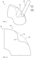
- Figures 9 and 10 disclose an alternative solution which differs from the one shown in previous Figures 7 and 8 in that different pushing element 30 is used. Further, in Figures 7 and 8 the pushing element 30 is moved in longitudinal direction towards the outer surface of the inlet tube 18, whereas in Figures 9 and 10 an outer surface of the pushing element 30 is pressed against the inlet tube 18. Thereby in these two alternative solutions differently shaped deformations and homogenizing element 24 are formed. The shapes and dimensions of the formed homogenizing elements 24 can be adjusted by movement length of the pushing element 30 as well as by dimensions and shapes of the pushing elements.
Landscapes
- Engineering & Computer Science (AREA)
- Geology (AREA)
- Life Sciences & Earth Sciences (AREA)
- Mining & Mineral Resources (AREA)
- Geochemistry & Mineralogy (AREA)
- Fluid Mechanics (AREA)
- Environmental & Geological Engineering (AREA)
- General Life Sciences & Earth Sciences (AREA)
- Physics & Mathematics (AREA)
- Mechanical Engineering (AREA)
- Chemical & Material Sciences (AREA)
- Dispersion Chemistry (AREA)
- Chemical Kinetics & Catalysis (AREA)
- Analytical Chemistry (AREA)
- Sampling And Sample Adjustment (AREA)
- Earth Drilling (AREA)
- Investigation Of Foundation Soil And Reinforcement Of Foundation Soil By Compacting Or Drainage (AREA)
Claims (8)
- Einlassrohr (18) einer Probenentnahmeanordnung eines Gesteinsbohrgerätes (1);wobei das Einlassrohr (18) konfiguriert ist, um einen Strom aus Bohrklein und Luft zu einer Entnahmestelle (SP) zu leiten;und das Einlassrohr (18) eine innere Querschnittsform und -abmessungen aufweist;und wobei das Einlassrohr (18) weiter einen Homogenisierungsabschnitt (23) umfasst, wobei der innere Querschnitt des Einlassrohres (18) mindestens ein Homogenisierungselement (24) umfasst, das eine physische Diskontinuitätsstelle bildet, wobei sich Form und Abmessungen des inneren Querschnitts lokal von Abschnitten vor und nach dem Homogenisierungsabschnitt (23) unterscheiden, und wobei das Homogenisierungselement konfiguriert ist, um Störungen in der Strömung zu erzeugen und dadurch die Partikelverteilung des Bohrkleins im Strom im Abschnitt nach dem Homogenisierungsabschnitt (23) und vor der Entnahmestelle (SP) zu homogenisieren;dadurch gekennzeichnet, dassdas Homogenisierungselement (24) ein aktives steuerbares Element ist, das den Homogenisierungsabschnitt (23) selektiv mit der physischen Diskontinuitätsstelle versieht.
- Einlassrohr nach Anspruch 1, dadurch gekennzeichnet, dass
das Einlassrohr (18) eine Biegung (25) umfasst und sich der Homogenisierungsabschnitt (23) an der Biegung (25) befindet. - Einlassrohranordnung nach Anspruch 1 oder 2, dadurch gekennzeichnet, dass
das Homogenisierungselement (24) ein selektiv expandierbares Element (29) ist. - Einlassrohranordnung nach Anspruch 1 oder 2, dadurch gekennzeichnet, dass
das Einlassrohr (18) aus elastischem Material hergestellt ist, und mindestens eine Betätigungsvorrichtung (A) am Homogenisierungsabschnitt (23) zum Leiten einer externen Kraft (F) auf eine Außenoberflächenseite des Einlassrohres (18) zum selektiven Verursachen einer reversiblen Verformung der Struktur des Einlassrohres (18) am Homogenisierungsabschnitt (23) umfasst, sodass Material einer Wand des Einlassrohres (18) nach innen hervorsteht, wodurch das Einlassrohr (18) mit einer inneren Ausbuchtung (31) versehen wird, die als das erwähnte Homogenisierungselement (24) dient. - Gesteinsbohrgerät (1), umfassend:einen beweglichen Träger (2);mindestens einen Bohrausleger (3), der auf dem Träger (2) montiert ist und eine Gesteinsbohreinheit (4) umfasst, die mit einer Gesteinsbohrmaschine (6) versehen ist;ein Staubsammelsystem (10) zum Entfernen von Bohrklein aus einer Öffnung eines Bohrlochs (12), wobei das Staubsammelsystem (10) mit einer Saugeinheit (11), Staubsammelrohren (13) und mindestens einem Abscheider (15) zum Abscheiden von Feststoffpartikeln aus einem Strom versehen ist, der Luft und das Bohrklein enthält; undmindestens eine Entnahmestelle (SP) zur Probenentnahme aus dem Strom;dadurch gekennzeichnet, dasssich die Entnahmestelle (SP) vor dem Abscheider (15) befindet, sodass der Strom an der Entnahmestelle (SP) noch unabgeschieden ist;und ein Einlassrohr (18) mit einem aktiv steuerbaren Homogenisierungselement (24) in dem Staubsammelsystem (10) vorhanden ist, das der Entnahmestelle (SP) vorausgeht und einem der vorstehenden Ansprüche 1-4 entspricht.
- Verfahren zur Probennahme in einem Gesteinsbohrgerät (1),
wobei das Verfahren umfasst:Bohren von Bohrlöchern (5) in eine Gesteinsoberfläche;Sammeln des erzeugten Bohrkleins aus einer Öffnung der Bohrlöcher (12) während des Bohrens anhand eines Staubsammelsystems (10);Entnehmen von Proben eines Stroms, der Luft und Bohrklein enthält, an einer Entnahmestelle (SP) des Staubsammelsystems (10) während des Bohrens; undVersehen des Staubsammelsystems (10) mit einem Einlassrohr (18) vor der Entnahmestelle (SP);gekennzeichnet durchaktives Ändern der inneren Querschnittsform und -abmessungen des Einlassrohrs (18) lokal zum Verteilen von Bohrkleinpartikeln (P) gleichmäßig im Strom über den inneren Querschnitt des Einlassrohres (18), wobei die Proben stromabwärts der erwähnten Partikelverteilung entnommen werden. - Verfahren nach Anspruch 6, gekennzeichnet durch
Drücken in Querrichtung einer reversiblen Verformung (28) auf eine elastische Wandstruktur des Einlassrohres (18) am Homogenisierungsabschnitt (23) zum Ändern der inneren Querschnittsform und -abmessungen des Einlassrohres (18) lokal anhand einer inneren Ausbuchtung (31), die als Reaktion auf das Drücken gebildet wird. - Verfahren nach Anspruch 6 oder 7, gekennzeichnet durch
Steuern der Änderung der inneren Querschnittsform und -abmessungen des Einlassrohres (18) unter Steuerung einer Steuereinheit (CU).
Priority Applications (5)
| Application Number | Priority Date | Filing Date | Title |
|---|---|---|---|
| FIEP22182452.7T FI4299873T3 (fi) | 2022-07-01 | 2022-07-01 | Tuloputki, kallioporauslaitteisto ja näytteenottomenetelmä |
| EP22182452.7A EP4299873B1 (de) | 2022-07-01 | 2022-07-01 | Einlassrohr, gesteinsbohrvorrichtung und verfahren zur probenahme |
| AU2023203599A AU2023203599B2 (en) | 2022-07-01 | 2023-06-09 | Inlet tube, rock drilling rig and method of sampling |
| JP2023106266A JP7561921B2 (ja) | 2022-07-01 | 2023-06-28 | 導入チューブ、削岩リグ、およびサンプリングの方法 |
| US18/216,268 US12173570B2 (en) | 2022-07-01 | 2023-06-29 | Inlet tube, rock drilling rig and method of sampling |
Applications Claiming Priority (1)
| Application Number | Priority Date | Filing Date | Title |
|---|---|---|---|
| EP22182452.7A EP4299873B1 (de) | 2022-07-01 | 2022-07-01 | Einlassrohr, gesteinsbohrvorrichtung und verfahren zur probenahme |
Publications (2)
| Publication Number | Publication Date |
|---|---|
| EP4299873A1 EP4299873A1 (de) | 2024-01-03 |
| EP4299873B1 true EP4299873B1 (de) | 2025-01-01 |
Family
ID=82492768
Family Applications (1)
| Application Number | Title | Priority Date | Filing Date |
|---|---|---|---|
| EP22182452.7A Active EP4299873B1 (de) | 2022-07-01 | 2022-07-01 | Einlassrohr, gesteinsbohrvorrichtung und verfahren zur probenahme |
Country Status (5)
| Country | Link |
|---|---|
| US (1) | US12173570B2 (de) |
| EP (1) | EP4299873B1 (de) |
| JP (1) | JP7561921B2 (de) |
| AU (1) | AU2023203599B2 (de) |
| FI (1) | FI4299873T3 (de) |
Families Citing this family (1)
| Publication number | Priority date | Publication date | Assignee | Title |
|---|---|---|---|---|
| EP4299873B1 (de) * | 2022-07-01 | 2025-01-01 | Sandvik Mining and Construction Oy | Einlassrohr, gesteinsbohrvorrichtung und verfahren zur probenahme |
Family Cites Families (39)
| Publication number | Priority date | Publication date | Assignee | Title |
|---|---|---|---|---|
| US1981570A (en) * | 1932-09-03 | 1934-11-20 | Price Stanley | Dust collector for drills |
| US2930967A (en) * | 1953-12-29 | 1960-03-29 | Gulf Research Development Co | Method and apparatus for logging drilling fluid |
| US3045769A (en) * | 1958-09-19 | 1962-07-24 | Westinghouse Air Brake Co | Rock drill guiding and cuttings disposal |
| US3460858A (en) * | 1966-08-19 | 1969-08-12 | Wirth & Co Kg A | Boring device |
| SE355840B (de) * | 1971-09-08 | 1973-05-07 | Atlas Copco Ab | |
| US3916634A (en) * | 1973-03-12 | 1975-11-04 | Roy J Woodruff | Method for forming holes in earth and setting subterranean structures therein |
| JPS5547632Y2 (de) * | 1976-09-06 | 1980-11-07 | ||
| US4164960A (en) * | 1978-02-13 | 1979-08-21 | Early California Industries Inc. | Apparatus for mixing fluids |
| SE427309B (sv) * | 1979-04-27 | 1983-03-21 | Per Olof Jonell | Forfarande och maskin for att konstatera forekomsten av vissa bestandsdelar i marken varvid en borr med hjelp av en borrmaskin neddrives i ett markavsnitt |
| JPS58172589U (ja) * | 1982-05-14 | 1983-11-18 | 古河鉱業株式会社 | 穿孔機用集塵器の粉塵輸送管 |
| SU1088782A1 (ru) * | 1983-03-28 | 1984-04-30 | Киевский Ордена Ленина Политехнический Институт Им.50-Летия Великой Октябрьской Социалистической Революции | Кавитационный реактор |
| SU1099990A1 (ru) * | 1983-04-18 | 1984-06-30 | Fedotkin Igor M | Кавитационный реактор дл обработки потока материалов |
| DE3634149A1 (de) * | 1985-11-08 | 1987-05-14 | Friedhelm Porsfeld | Druckluftbetriebenes geraet zur gesteinsbearbeitung |
| GB2186809B (en) * | 1986-02-21 | 1990-04-11 | Prad Res & Dev Nv | Homogenising and metering the flow of a multiphase mixture of fluids |
| DE3712925A1 (de) | 1987-04-16 | 1988-11-03 | Janke & Kunkel Kg | Kuehler insbesondere fuer rotationsverdampfer |
| JP3970410B2 (ja) * | 1998-02-27 | 2007-09-05 | 古河機械金属株式会社 | 繰粉検出装置 |
| AU743936B2 (en) * | 1999-02-10 | 2002-02-07 | Drilling Project Services Australia Pty Ltd | Apparatus for and method of automatic sampling of drill cuttings |
| RO121533B1 (ro) * | 2001-12-04 | 2007-10-30 | Instalaţie de verificare a presiunii probelor de fluid, colectate în sonde | |
| GB0220814D0 (en) * | 2002-09-09 | 2002-10-16 | Aroussi Abdelwahab | A generator of homogeneous mix of particulate laden flows in pipes |
| FI20045197A0 (fi) * | 2004-05-31 | 2004-05-31 | Sandvik Tamrock Oy | Porasoijan imusuppilo ja aloitusohjain |
| FI118038B (fi) * | 2005-11-24 | 2007-06-15 | Sandvik Tamrock Oy | Järjestely pölyn käsittelemiseksi |
| FI20085848A7 (fi) | 2008-09-10 | 2010-03-11 | Sandvik Mining & Construction Oy | Menetelmä porasoijan käsittelemiseksi, kallionporauslaitteen pölynkeruujärjestelmä sekä vaihdinyksikkö |
| JPWO2010029763A1 (ja) | 2008-09-12 | 2012-02-02 | パナソニック株式会社 | 中継装置及び中継方法 |
| BE1018675A3 (fr) * | 2009-03-03 | 2011-06-07 | Fib Belgium Sa | Dispositif de dosage d'un melange gazeux. |
| RU100806U1 (ru) * | 2010-08-27 | 2010-12-27 | Общество с ограниченной ответственностью "Совет Всероссийского общества изобретателей и рационализаторов научно-исследовательских институтов нефтяной и газовой промышленности" (ООО "Совет ВОИР НИИНГП") | Устьевой скважинный пробоотборник |
| NL2005612C2 (en) * | 2010-11-02 | 2012-05-03 | Kimman Process Solutions B V | A method and system for at least temporarily homogenizing a fluid flow in a pipeline. |
| FI125722B (fi) * | 2012-09-19 | 2016-01-29 | Erimek Oy | Näytteenottolaitteisto |
| EP2886789B1 (de) * | 2013-12-20 | 2019-02-27 | Sandvik Mining and Construction Oy | Bohrwerkzeughalterung und Verfahren zur Einfassung der Bohrwerkzeughalterung und Verfahren zur Einfassung |
| JP6577313B2 (ja) | 2015-09-25 | 2019-09-18 | 古河ロックドリル株式会社 | くり粉サンプリング装置およびこれを備える穿孔機械 |
| KR20170050076A (ko) * | 2015-10-29 | 2017-05-11 | 주식회사 엘지화학 | 혼합기 및 이를 포함하는 반응기 |
| FI127186B (fi) * | 2016-06-23 | 2017-12-29 | Erimek Oy | Porauslaitteisto ja menetelmä tutkimusnäytteen keräämiseksi porauslaitteistosta |
| US10416015B2 (en) * | 2016-07-07 | 2019-09-17 | Schlumberger Technology Corporation | Representative sampling of multiphase fluids |
| EP3699395B1 (de) * | 2019-02-22 | 2022-11-30 | OneSubsea IP UK Limited | Teilchenüberwachungsanordnung für ölfeldproduktion |
| CN113230916B (zh) * | 2021-04-16 | 2022-04-01 | 上海交通大学 | 垂直混合式连续谱气泡发生器及连续谱气泡的制作方法 |
| EP4299873B1 (de) * | 2022-07-01 | 2025-01-01 | Sandvik Mining and Construction Oy | Einlassrohr, gesteinsbohrvorrichtung und verfahren zur probenahme |
| EP4299874A1 (de) * | 2022-07-01 | 2024-01-03 | Sandvik Mining and Construction Oy | Homogenisator, gesteinsbohrkopf und verfahren zur probenahme |
| CN218189337U (zh) * | 2022-08-10 | 2023-01-03 | 四川农业大学 | 一种高效的乳液制备均质机 |
| FI131328B1 (fi) * | 2022-10-04 | 2025-02-24 | Erimek Oy | Näytteenottojärjestelyn näytteenottoputki |
| CN115582038B (zh) * | 2022-11-07 | 2025-11-21 | 安德里茨(中国)有限公司 | 射流混合器 |
-
2022
- 2022-07-01 EP EP22182452.7A patent/EP4299873B1/de active Active
- 2022-07-01 FI FIEP22182452.7T patent/FI4299873T3/fi active
-
2023
- 2023-06-09 AU AU2023203599A patent/AU2023203599B2/en active Active
- 2023-06-28 JP JP2023106266A patent/JP7561921B2/ja active Active
- 2023-06-29 US US18/216,268 patent/US12173570B2/en active Active
Also Published As
| Publication number | Publication date |
|---|---|
| US20240003207A1 (en) | 2024-01-04 |
| EP4299873A1 (de) | 2024-01-03 |
| JP2024009769A (ja) | 2024-01-23 |
| FI4299873T3 (fi) | 2025-02-06 |
| AU2023203599B2 (en) | 2024-11-14 |
| AU2023203599A1 (en) | 2024-01-18 |
| JP7561921B2 (ja) | 2024-10-04 |
| US12173570B2 (en) | 2024-12-24 |
Similar Documents
| Publication | Publication Date | Title |
|---|---|---|
| US12173570B2 (en) | Inlet tube, rock drilling rig and method of sampling | |
| EP2886789B1 (de) | Bohrwerkzeughalterung und Verfahren zur Einfassung der Bohrwerkzeughalterung und Verfahren zur Einfassung | |
| JP5289570B2 (ja) | 切削物処理方法、削岩リグのダスト回収システムおよび切替ユニット | |
| US12139979B2 (en) | Homogenizer, rock drilling rig and method of sampling | |
| US11053794B2 (en) | Drilling apparatus and method for collecting research sample | |
| US10815742B2 (en) | Separator and method of separation with a pressure differential device | |
| EP2736647A1 (de) | Magnetseparator, verfahren zu dessen betrieb und dessen verwendung | |
| CA3061071A1 (en) | Apparatus for feeding tube elements, rock drilling rig and method of supporting drill hole openings | |
| KR101937475B1 (ko) | 호스 연결 장치 | |
| KR101544769B1 (ko) | 연약 사질지반 확장형 시료채취장치 | |
| KR20160004494A (ko) | 도넛 함마 장치 및 이를 이용한 굴착 방법 | |
| US10794131B2 (en) | System, apparatus and method for adjusting a weir | |
| US5176726A (en) | Dust collectors | |
| AU2006201921A1 (en) | Drilling apparatus and method | |
| WO2000055469A1 (en) | Method and apparatus for underground drilling | |
| CA2581682A1 (en) | Apparatus and method for moving drilled cuttings |
Legal Events
| Date | Code | Title | Description |
|---|---|---|---|
| PUAI | Public reference made under article 153(3) epc to a published international application that has entered the european phase |
Free format text: ORIGINAL CODE: 0009012 |
|
| STAA | Information on the status of an ep patent application or granted ep patent |
Free format text: STATUS: THE APPLICATION HAS BEEN PUBLISHED |
|
| AK | Designated contracting states |
Kind code of ref document: A1 Designated state(s): AL AT BE BG CH CY CZ DE DK EE ES FI FR GB GR HR HU IE IS IT LI LT LU LV MC MK MT NL NO PL PT RO RS SE SI SK SM TR |
|
| STAA | Information on the status of an ep patent application or granted ep patent |
Free format text: STATUS: REQUEST FOR EXAMINATION WAS MADE |
|
| 17P | Request for examination filed |
Effective date: 20240703 |
|
| RBV | Designated contracting states (corrected) |
Designated state(s): AL AT BE BG CH CY CZ DE DK EE ES FI FR GB GR HR HU IE IS IT LI LT LU LV MC MK MT NL NO PL PT RO RS SE SI SK SM TR |
|
| GRAP | Despatch of communication of intention to grant a patent |
Free format text: ORIGINAL CODE: EPIDOSNIGR1 |
|
| STAA | Information on the status of an ep patent application or granted ep patent |
Free format text: STATUS: GRANT OF PATENT IS INTENDED |
|
| RIC1 | Information provided on ipc code assigned before grant |
Ipc: E21B 21/01 20060101ALI20240813BHEP Ipc: E21B 49/00 20060101ALI20240813BHEP Ipc: E21B 21/06 20060101ALI20240813BHEP Ipc: B01F 23/30 20220101ALI20240813BHEP Ipc: B01F 23/00 20220101ALI20240813BHEP Ipc: E21B 21/015 20060101ALI20240813BHEP Ipc: E21B 7/02 20060101AFI20240813BHEP |
|
| INTG | Intention to grant announced |
Effective date: 20240910 |
|
| GRAS | Grant fee paid |
Free format text: ORIGINAL CODE: EPIDOSNIGR3 |
|
| GRAA | (expected) grant |
Free format text: ORIGINAL CODE: 0009210 |
|
| STAA | Information on the status of an ep patent application or granted ep patent |
Free format text: STATUS: THE PATENT HAS BEEN GRANTED |
|
| AK | Designated contracting states |
Kind code of ref document: B1 Designated state(s): AL AT BE BG CH CY CZ DE DK EE ES FI FR GB GR HR HU IE IS IT LI LT LU LV MC MK MT NL NO PL PT RO RS SE SI SK SM TR |
|
| REG | Reference to a national code |
Ref country code: GB Ref legal event code: FG4D |
|
| REG | Reference to a national code |
Ref country code: DE Ref legal event code: R096 Ref document number: 602022009255 Country of ref document: DE |
|
| REG | Reference to a national code |
Ref country code: CH Ref legal event code: EP |
|
| REG | Reference to a national code |
Ref country code: IE Ref legal event code: FG4D |
|
| REG | Reference to a national code |
Ref country code: FI Ref legal event code: FGE |
|
| REG | Reference to a national code |
Ref country code: SE Ref legal event code: TRGR |
|
| REG | Reference to a national code |
Ref country code: LT Ref legal event code: MG9D |
|
| REG | Reference to a national code |
Ref country code: NL Ref legal event code: MP Effective date: 20250101 |
|
| REG | Reference to a national code |
Ref country code: AT Ref legal event code: MK05 Ref document number: 1756402 Country of ref document: AT Kind code of ref document: T Effective date: 20250101 |
|
| PG25 | Lapsed in a contracting state [announced via postgrant information from national office to epo] |
Ref country code: NL Free format text: LAPSE BECAUSE OF FAILURE TO SUBMIT A TRANSLATION OF THE DESCRIPTION OR TO PAY THE FEE WITHIN THE PRESCRIBED TIME-LIMIT Effective date: 20250101 |
|
| PG25 | Lapsed in a contracting state [announced via postgrant information from national office to epo] |
Ref country code: PL Free format text: LAPSE BECAUSE OF FAILURE TO SUBMIT A TRANSLATION OF THE DESCRIPTION OR TO PAY THE FEE WITHIN THE PRESCRIBED TIME-LIMIT Effective date: 20250101 |
|
| PG25 | Lapsed in a contracting state [announced via postgrant information from national office to epo] |
Ref country code: ES Free format text: LAPSE BECAUSE OF FAILURE TO SUBMIT A TRANSLATION OF THE DESCRIPTION OR TO PAY THE FEE WITHIN THE PRESCRIBED TIME-LIMIT Effective date: 20250101 |
|
| PG25 | Lapsed in a contracting state [announced via postgrant information from national office to epo] |
Ref country code: IS Free format text: LAPSE BECAUSE OF FAILURE TO SUBMIT A TRANSLATION OF THE DESCRIPTION OR TO PAY THE FEE WITHIN THE PRESCRIBED TIME-LIMIT Effective date: 20250501 Ref country code: NO Free format text: LAPSE BECAUSE OF FAILURE TO SUBMIT A TRANSLATION OF THE DESCRIPTION OR TO PAY THE FEE WITHIN THE PRESCRIBED TIME-LIMIT Effective date: 20250401 |
|
| PG25 | Lapsed in a contracting state [announced via postgrant information from national office to epo] |
Ref country code: HR Free format text: LAPSE BECAUSE OF FAILURE TO SUBMIT A TRANSLATION OF THE DESCRIPTION OR TO PAY THE FEE WITHIN THE PRESCRIBED TIME-LIMIT Effective date: 20250101 |
|
| PG25 | Lapsed in a contracting state [announced via postgrant information from national office to epo] |
Ref country code: PT Free format text: LAPSE BECAUSE OF FAILURE TO SUBMIT A TRANSLATION OF THE DESCRIPTION OR TO PAY THE FEE WITHIN THE PRESCRIBED TIME-LIMIT Effective date: 20250502 Ref country code: LV Free format text: LAPSE BECAUSE OF FAILURE TO SUBMIT A TRANSLATION OF THE DESCRIPTION OR TO PAY THE FEE WITHIN THE PRESCRIBED TIME-LIMIT Effective date: 20250101 |
|
| PGFP | Annual fee paid to national office [announced via postgrant information from national office to epo] |
Ref country code: FR Payment date: 20250623 Year of fee payment: 4 |
|
| PG25 | Lapsed in a contracting state [announced via postgrant information from national office to epo] |
Ref country code: GR Free format text: LAPSE BECAUSE OF FAILURE TO SUBMIT A TRANSLATION OF THE DESCRIPTION OR TO PAY THE FEE WITHIN THE PRESCRIBED TIME-LIMIT Effective date: 20250402 Ref country code: BG Free format text: LAPSE BECAUSE OF FAILURE TO SUBMIT A TRANSLATION OF THE DESCRIPTION OR TO PAY THE FEE WITHIN THE PRESCRIBED TIME-LIMIT Effective date: 20250101 |
|
| PG25 | Lapsed in a contracting state [announced via postgrant information from national office to epo] |
Ref country code: AT Free format text: LAPSE BECAUSE OF FAILURE TO SUBMIT A TRANSLATION OF THE DESCRIPTION OR TO PAY THE FEE WITHIN THE PRESCRIBED TIME-LIMIT Effective date: 20250101 |
|
| PG25 | Lapsed in a contracting state [announced via postgrant information from national office to epo] |
Ref country code: CZ Free format text: LAPSE BECAUSE OF FAILURE TO SUBMIT A TRANSLATION OF THE DESCRIPTION OR TO PAY THE FEE WITHIN THE PRESCRIBED TIME-LIMIT Effective date: 20250101 |
|
| PGFP | Annual fee paid to national office [announced via postgrant information from national office to epo] |
Ref country code: SE Payment date: 20250610 Year of fee payment: 4 |
|
| REG | Reference to a national code |
Ref country code: DE Ref legal event code: R097 Ref document number: 602022009255 Country of ref document: DE |
|
| PG25 | Lapsed in a contracting state [announced via postgrant information from national office to epo] |
Ref country code: SM Free format text: LAPSE BECAUSE OF FAILURE TO SUBMIT A TRANSLATION OF THE DESCRIPTION OR TO PAY THE FEE WITHIN THE PRESCRIBED TIME-LIMIT Effective date: 20250101 |
|
| PGFP | Annual fee paid to national office [announced via postgrant information from national office to epo] |
Ref country code: FI Payment date: 20250715 Year of fee payment: 4 |
|
| PG25 | Lapsed in a contracting state [announced via postgrant information from national office to epo] |
Ref country code: DK Free format text: LAPSE BECAUSE OF FAILURE TO SUBMIT A TRANSLATION OF THE DESCRIPTION OR TO PAY THE FEE WITHIN THE PRESCRIBED TIME-LIMIT Effective date: 20250101 |
|
| PG25 | Lapsed in a contracting state [announced via postgrant information from national office to epo] |
Ref country code: IT Free format text: LAPSE BECAUSE OF FAILURE TO SUBMIT A TRANSLATION OF THE DESCRIPTION OR TO PAY THE FEE WITHIN THE PRESCRIBED TIME-LIMIT Effective date: 20250101 |
|
| PG25 | Lapsed in a contracting state [announced via postgrant information from national office to epo] |
Ref country code: EE Free format text: LAPSE BECAUSE OF FAILURE TO SUBMIT A TRANSLATION OF THE DESCRIPTION OR TO PAY THE FEE WITHIN THE PRESCRIBED TIME-LIMIT Effective date: 20250101 |
|
| PG25 | Lapsed in a contracting state [announced via postgrant information from national office to epo] |
Ref country code: RO Free format text: LAPSE BECAUSE OF FAILURE TO SUBMIT A TRANSLATION OF THE DESCRIPTION OR TO PAY THE FEE WITHIN THE PRESCRIBED TIME-LIMIT Effective date: 20250101 |
|
| PG25 | Lapsed in a contracting state [announced via postgrant information from national office to epo] |
Ref country code: SK Free format text: LAPSE BECAUSE OF FAILURE TO SUBMIT A TRANSLATION OF THE DESCRIPTION OR TO PAY THE FEE WITHIN THE PRESCRIBED TIME-LIMIT Effective date: 20250101 |
|
| PLBE | No opposition filed within time limit |
Free format text: ORIGINAL CODE: 0009261 |
|
| STAA | Information on the status of an ep patent application or granted ep patent |
Free format text: STATUS: NO OPPOSITION FILED WITHIN TIME LIMIT |
|
| REG | Reference to a national code |
Ref country code: CH Ref legal event code: L10 Free format text: ST27 STATUS EVENT CODE: U-0-0-L10-L00 (AS PROVIDED BY THE NATIONAL OFFICE) Effective date: 20251112 |
|
| 26N | No opposition filed |
Effective date: 20251002 |
|
| REG | Reference to a national code |
Ref country code: DE Ref legal event code: R119 Ref document number: 602022009255 Country of ref document: DE |
|
| REG | Reference to a national code |
Ref country code: CH Ref legal event code: H13 Free format text: ST27 STATUS EVENT CODE: U-0-0-H10-H13 (AS PROVIDED BY THE NATIONAL OFFICE) Effective date: 20260224 |
|
| PG25 | Lapsed in a contracting state [announced via postgrant information from national office to epo] |
Ref country code: LU Free format text: LAPSE BECAUSE OF NON-PAYMENT OF DUE FEES Effective date: 20250701 |