EP4299874A1 - Homogenisator, gesteinsbohrkopf und verfahren zur probenahme - Google Patents
Homogenisator, gesteinsbohrkopf und verfahren zur probenahme Download PDFInfo
- Publication number
- EP4299874A1 EP4299874A1 EP22182453.5A EP22182453A EP4299874A1 EP 4299874 A1 EP4299874 A1 EP 4299874A1 EP 22182453 A EP22182453 A EP 22182453A EP 4299874 A1 EP4299874 A1 EP 4299874A1
- Authority
- EP
- European Patent Office
- Prior art keywords
- flow
- homogenizer
- drilling
- air
- dust collecting
- Prior art date
- Legal status (The legal status is an assumption and is not a legal conclusion. Google has not performed a legal analysis and makes no representation as to the accuracy of the status listed.)
- Pending
Links
Images


Classifications
-
- E—FIXED CONSTRUCTIONS
- E21—EARTH OR ROCK DRILLING; MINING
- E21B—EARTH OR ROCK DRILLING; OBTAINING OIL, GAS, WATER, SOLUBLE OR MELTABLE MATERIALS OR A SLURRY OF MINERALS FROM WELLS
- E21B21/00—Methods or apparatus for flushing boreholes, e.g. by use of exhaust air from motor
- E21B21/01—Arrangements for handling drilling fluids or cuttings outside the borehole, e.g. mud boxes
- E21B21/015—Means engaging the bore entrance, e.g. hoods for collecting dust
-
- E—FIXED CONSTRUCTIONS
- E21—EARTH OR ROCK DRILLING; MINING
- E21B—EARTH OR ROCK DRILLING; OBTAINING OIL, GAS, WATER, SOLUBLE OR MELTABLE MATERIALS OR A SLURRY OF MINERALS FROM WELLS
- E21B7/00—Special methods or apparatus for drilling
- E21B7/02—Drilling rigs characterised by means for land transport with their own drive, e.g. skid mounting or wheel mounting
- E21B7/025—Rock drills, i.e. jumbo drills
-
- E—FIXED CONSTRUCTIONS
- E21—EARTH OR ROCK DRILLING; MINING
- E21B—EARTH OR ROCK DRILLING; OBTAINING OIL, GAS, WATER, SOLUBLE OR MELTABLE MATERIALS OR A SLURRY OF MINERALS FROM WELLS
- E21B21/00—Methods or apparatus for flushing boreholes, e.g. by use of exhaust air from motor
- E21B21/01—Arrangements for handling drilling fluids or cuttings outside the borehole, e.g. mud boxes
- E21B21/011—Dust eliminating or dust removing while drilling
-
- E—FIXED CONSTRUCTIONS
- E21—EARTH OR ROCK DRILLING; MINING
- E21B—EARTH OR ROCK DRILLING; OBTAINING OIL, GAS, WATER, SOLUBLE OR MELTABLE MATERIALS OR A SLURRY OF MINERALS FROM WELLS
- E21B21/00—Methods or apparatus for flushing boreholes, e.g. by use of exhaust air from motor
- E21B21/06—Arrangements for treating drilling fluids outside the borehole
- E21B21/07—Arrangements for treating drilling fluids outside the borehole for treating dust-laden gaseous fluids
-
- E—FIXED CONSTRUCTIONS
- E21—EARTH OR ROCK DRILLING; MINING
- E21C—MINING OR QUARRYING
- E21C35/00—Details of, or accessories for, machines for slitting or completely freeing the mineral from the seam, not provided for in groups E21C25/00 - E21C33/00, E21C37/00 or E21C39/00
- E21C35/22—Equipment for preventing the formation of, or for removal of, dust
- E21C35/223—Equipment associated with mining machines for sucking dust-laden air from the cutting area, with or without cleaning of the air
Definitions
- the invention relates to a homogenizer intended to be mounted to dust collecting system of rock drilling rig.
- the homogenizer is designed for affecting to properties of flow in the dust collecting system.
- the invention further relates to a rock drilling rig and to a method of taking samples of drilling cuttings.
- An object of the invention is to provide a novel and improved homogenizer, rock drilling rig and method for taking samples.
- the homogenizer according to the invention is characterized by the characterizing features of the first independent apparatus claim.
- the rock drilling rig according to the invention is characterized by the characterizing features of the second independent apparatus claim.
- the method according to the invention is characterized by the characterizing features of the independent method claim.
- a dust collecting system of a rock drilling rig can be provided with a homogenizer for homogenizing flow containing air and drilling cuttings.
- the homogenizer comprises a channel part through which the flow is directed and one or more air jets arranged on an inner surface of the channel part for directing air blows to the flow.
- the aim of the air blows is to generate disturbances in the flow and to thereby homogenize particle distribution of the drilling cuttings in the flow.
- the flow inside the flow channel or channel part is disturbed pneumatically by directing pressurized air in transverse direction of the flow so that the drilling cutting particles with different sizes are spread more evenly.
- An advantage of the disclosed solution is that representative samples of the drilling cuttings after the homogenizer can be taken when the particles with different size are spread more evenly inside the inlet tube. This way quality of the samples can be improved and more accurate and reliable analyzing results can be achieved.
- a further advantage is that the disclosed solution is relatively simple and inexpensive. Since the solution does not contain any movable elements or complicated mechanisms, the solution is also durable and reliable. There are no physical objects in the homogenizer which were subjected to abrasive wearing of the drilling cutting particles. The disclosed homogenizer can also be retrofitted easily to the existing dust collecting systems of different rock drilling rigs.
- a further advantage is that the disclosed solution does not narrow physically the air channel and throttle the flow. This way, undesired flow resistances in the channel can be avoided.
- number of the air jets is one. In some cases, one single air jet may be sufficient to cause needed particle spreading in the flow.
- the homogenizer there may be several air jets in the homogenizer.
- the homogenizer can have versatile control possibilities and can be adjusted to different flow situations.
- orientation and magnitude of the air blows directed to the flow can be designed case by case.
- Flow control simulation and modelling programs can be utilized for determining the properties of the disclosed pneumatic spreading control system.
- the air jet comprises a nozzle element provided with a jet orifice and is connectable to a pneumatic channel.
- the nozzle element further comprises mounting elements for mounting to air jet to the channel part.
- the air jet comprises a nozzle element provided with several jet orifices.
- the channel part comprises a bend and the at least one air jet is located at the bend.
- the air blows are directed to the flow at the bend. It has been noted in experiments that the effect of the pneumatic control impacts is intensified when they occur at the bend.
- the use of the bend is also beneficial because there is typically a need to direct tubes and hoses of the dust collection in angular positions and especially at areas close to separators and other devices. In the bends the particles are often moved in the flow towards an outer curve side of the bend, whereby this undesirable phenomena caused by inertia of the particles can be compensated by executing the air blows.
- the bend may be 90°, or substantially 90°.
- the bend may also be any bend between 45 - 135°.
- the channel part or portion may in some cases be without any bend whereby the homogenizing section and the homogenizing element are located at a straight section.
- the channel part comprises a bend with an inner curve and an outer curve and wherein the at least one air jet is provided on the outer curve of the bend.
- the air blows are located at the outer curve of the bend which is the most critical point where the solid particles tend to concentrate in the flow. Directing the air blows at the outer curve side has been found to be effective.
- the air jets are located only on the outer curve side of the bend.
- the homogenizer comprises several air jets in transverse cross-section of the channel part whereby the several air jets are orientated in different radial directions relative to each other.
- combined effect of several pneumatic guiding streams can be directed to the solid particles of the flow for intensifying the desired spreading action.
- the homogenizer comprises several air jets which are located at a distance from each other when seen in the flow direction. In other words, there may be two, three or even more air jets one after each other.
- magnitudes of the air blows of the several air jets can be controlled under control of the control unit.
- magnitudes of the several air blows may be equal or different relative to each other.
- the homogenizer may comprise a nozzle arrangement provided with several nozzles and jet orifices. There may be different preassembled homogenizers with different nozzle settings whereby mounting and possible change of the homogenizer is quick and easy when so desired.
- the several air jets may be oriented, for example, at 10 - 45° angular intervals relative to each other when seen in longitudinal direction of the channel part. Size of the angular intervals between the air jets may be similar, or different angularities may be implemented.
- the magnitudes of the air blows of the at least one air jet is controllable under control of a control unit.
- the control unit can synchronize the air blows and the sample taking measures. It is possible to initiate the execution of the air blows before the sampling measures are started.
- An advantage is that the control unit can adjust the timing and co-operation between the spreading and sampling.
- the magnitudes of the air blows of the at least one air jet may be controlled by controlling pressure, or rate of flow, or both.
- magnitude of pressure used in the air jets may be 3 - 10 bars, for example.
- each of the air jets can be separately controllable.
- timing of the air blows, as well as magnitudes of the air blows can be controlled by means of the control unit.
- control unit can control the spreading and sampling measures fully automatically during the rock drilling.
- the disclosed solution relates to a rock drilling rig comprising: a movable carrier; at least one drilling boom mounted on the carrier and comprising a rock drilling unit provided with a rock drilling machine; a dust collecting system for removing drilling cuttings from an opening of a drilled hole, wherein the dust collecting system is provided with a suction unit, dust collecting tubing, and at least one separator for separating solid particles from flow containing air and the drilling cuttings; and at least one sampling point for taking samples of the flow. Further, the sampling point is located prior to the separator so that the flow is still unseparated at the sampling point; and there is a homogenizer in the dust collecting system preceding the sampling point.
- the homogenizer is in accordance with the features and embodiments disclosed in this document.
- the sampling point is located before any separation measures for the flow have been executed.
- An advantage of this is that the flow, where from the samples are taken, comprises all possible particles since nothing has been removed from the flow.
- the disclosed solution can be implemented in different kind of drilling techniques and purposes including for example production drilling and exploration drilling.
- the solution is suitable to be used in connection with top hammer drilling, DTH drilling and rotary drilling, for example.
- the dust collecting system comprises a first separator for separating coarse solid particles from the flow and a second separator for separating fine solid particles from the flow.
- the first separator may be located on the drilling boom whereas the second separator may be located on the carrier.
- the first separator may be a cyclone.
- the homogenizer and the sampling point are located just before the first separator.
- the rock drilling rig comprises at least one compressor for generating pneumatic pressure to a pneumatic system and wherein the homogenizer is connected to the pneumatic system and is controllable by at least one control valve.
- the disclosed solution relates also to a method of sampling in a rock drilling rig.
- the method comprises: drilling drill holes to a rock surface; collecting produced drilling cuttings from an opening of the drill holes during the drilling by means of a dust collecting system; and taking samples of flow containing air and drilling cuttings at a sampling point of the dust collecting system during the drilling.
- the method further comprises: providing the dust collecting system with a homogenizer before the sampling point; directing transverse air blows to the flow and thereby spreading drilling cutting particles in the flow to even out particle distribution of the flow; and taking the samples downstream the mentioned particle spreading.
- the method comprises providing one or more controlled gas streams in transverse direction of the flow of the drilling cutting particles and air for effecting to the solid particles of the flow.
- the solid particles can be directed in the flow in contactless manner with the help of air blows.
- the method comprises controlling the spreading of the solid particles in the flow by directing several air blows in different transverse directions towards the flow.
- the spreading and distribution of the solid particles can be intensified by implementing several air blows with different orientation.
- the method comprises providing the at least one air jet with continuous air flow during the selectively controlled spreading measures of the solid particles.
- the continuous air flow through the at least one air jet nozzle occurs during the sampling process.
- the method comprises directing pressure air pulses or impacts to the flow when executing the spreading of the solid particles.
- the air pulses, or impacts may in some cases be beneficial for the spreading of the solid particles.
- the air pulses may cause desired turbulence in the flow, for example.
- each of them can be arranged to direct similar of different air pulses to the flow.
- Figure 1 discloses a rock drilling rig 1 comprising a movable carrier 2 and a drilling boom 3 mounted on the carrier 2.
- the drilling boom 3 is provided with a rock drilling unit 4 for drilling drill holes 5 to a rock surface.
- the rock drilling unit 4 comprises a rock drilling machine 6 which may be arranged movably on a feed beam 7.
- the rock drilling machine 6 may comprise an impact device and a rotating device, or alternatively it may be a rotary drilling machine and may be without any impact device.
- a drilling tool 8 is connected to the rock drilling machine 6 and the drilling tool 8 may comprise one or more drill tubes and a drill bit 9 at its free end. During the drilling rock material is broken and drilling cuttings are formed in the drill hole 5. The drilling cuttings needs to be flushed away from the drill hole 5.
- pressurized air is produced by means of a compressor CO and the pressurized air is directed via the drilling tool 8 to a bottom of the drill hole 5 whereby drilling cuttings are flushed away.
- the drilling cuttings can be collected by a means of a duct collecting system 10 comprising a suction unit 11 for production negative pressure so that the drilling cuttings can be sucked from a drill hole opening 12 via dust collecting tubes 13.
- a main purpose of the dust collecting system 10 is to transfer the drilling cuttings away from the drill hole opening 12 so that visibility to the drilled target is good and no difficulties occur for the drilling process due to large amount of the material removed from the drill hole 5.
- the dust collecting system 5 may also comprise one or more separators for processing the collected material.
- the first separator 15 may be mounted on the drilling boom 3 and it may comprise a cyclone, for example.
- the second separator 16 may be mounted on the carrier 2 in connection with the suction unit 11, for example.
- a sampling device 17 for taking samples out of flow of drilling cuttings and air in the system is arranged before the first separator 15 whereby it is located prior to any separation phase. Further, a homogenizer 18 is arranged before the sampling device 17 for ensuring that the flow directed to the sampling device 17 is concentrated. The homogenizer 18 spreads the drilling cuttings in the flow so that proper samples can be taken from the flow.
- the homogenizer 18 operates by means of pressurized air wherefore pressure air is conveyed from an output port 19 of the compressor CO to a pressure feed line 20 of the homogenizer 18.
- the rock drilling rig 1 may comprise one or more control units CU for controlling the operation and actuators.
- the control unit CU may control the sampling device 17 and the homogenizer 18, for example. Some control situations and principles are disclosed above in this document.
- the control unit may comprise a processor for executing an input computer program product or algorithm, and it may be provided with sensing data and input control parameters.
- Figure 2 discloses a dust collecting system 10 for sucking drilling cuttings from a drill hole opening 12.
- the system 10 comprises dust collecting tubes 13 for transferring the collected flow via a homogenizer 18 to a sampling device 17 and only then to a separator 15.
- a sampling point SP is located between the homogenizer 18 and the separator 15.
- Samples SA are taken from the flow in accordance with a planned sampling schedule or procedure.
- the samples SA can be analyzed A either online 21 or later on in a laboratory 22.
- the sampling device 17 may comprise a tube or sampling pipe which is partly insertable inside the flow channel, and which is provided with an opening through which material to be collected passes during the sampling.
- the samples taken can be stored in receptacles or bags, for example.
- Figure 3 discloses that a homogenizer 18 comprises a channel part 23 for conveying flow of air and drilling cuttings through it.
- the channel part 23 is provided with one or more air jets 24 for directing air blows 25 towards the flow and causing thereby desired disturbance 26 in the flow.
- Figure 4 discloses a homogenizer 18 wherein one air jet 24 is arranged on a wall of a channel part 23. Feeding of pressurized air from a compressor CO can be controlled by means of a valve V which may be controlled by means of a control unit CU. Figure 4 shows that solid particles P in the flow are not distributed evenly, wherefore the particle distribution needs to be improved by directing air blows in transverse direction to the flow. After this pneumatic particle separation control easier and more reliable sampling is possible.
- Figure 5 discloses the same pneumatic control principle as disclosed in Figure 4 , but several air jets are utilized instead of one.
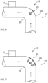
- Figures 6 and 7 both disclose that a channel part 23 of a homogenizer 18 comprises a bend 27 provided with an inner curve 28 and an outer curve 29.
- One or more air jets 24 are mounted on the outer curve 29 of the bend 27.
- cross-section of the channel part 23 may comprise one air jet 24 or several air jets arranged in different radial angles.
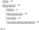
- an air jet 24 may comprise a nozzle element 30 comprising a frame 31 or body and mounting elements 32 for mounting it to a channel part. Further, there is one or more jet orifices 33 through which the air blows are directed.
- the nozzle element 30 is provided with a feed port or connection 34 for connecting it with a pneumatic channel for feeding pressure air.
- mounting of the nozzle element 30 comprises drilling a hole to a wall of the channel part, inserting the nozzle element 30 to the drilled hole and tightening the nozzle element 30 in place with screw members. Finally, the nozzle element is connected to the pneumatic channel.
Landscapes
- Engineering & Computer Science (AREA)
- Mining & Mineral Resources (AREA)
- Life Sciences & Earth Sciences (AREA)
- Geology (AREA)
- General Life Sciences & Earth Sciences (AREA)
- Geochemistry & Mineralogy (AREA)
- Physics & Mathematics (AREA)
- Environmental & Geological Engineering (AREA)
- Fluid Mechanics (AREA)
- Mechanical Engineering (AREA)
- Earth Drilling (AREA)
- Sampling And Sample Adjustment (AREA)
Priority Applications (4)
| Application Number | Priority Date | Filing Date | Title |
|---|---|---|---|
| EP22182453.5A EP4299874A1 (de) | 2022-07-01 | 2022-07-01 | Homogenisator, gesteinsbohrkopf und verfahren zur probenahme |
| AU2023203598A AU2023203598B2 (en) | 2022-07-01 | 2023-06-09 | Homogenizer, rock drilling rig and method of sampling |
| US18/216,291 US12139979B2 (en) | 2022-07-01 | 2023-06-29 | Homogenizer, rock drilling rig and method of sampling |
| JP2023106720A JP7689992B2 (ja) | 2022-07-01 | 2023-06-29 | ホモジナイザ、削岩リグ、および試料抽出の方法 |
Applications Claiming Priority (1)
| Application Number | Priority Date | Filing Date | Title |
|---|---|---|---|
| EP22182453.5A EP4299874A1 (de) | 2022-07-01 | 2022-07-01 | Homogenisator, gesteinsbohrkopf und verfahren zur probenahme |
Publications (1)
| Publication Number | Publication Date |
|---|---|
| EP4299874A1 true EP4299874A1 (de) | 2024-01-03 |
Family
ID=82492450
Family Applications (1)
| Application Number | Title | Priority Date | Filing Date |
|---|---|---|---|
| EP22182453.5A Pending EP4299874A1 (de) | 2022-07-01 | 2022-07-01 | Homogenisator, gesteinsbohrkopf und verfahren zur probenahme |
Country Status (4)
| Country | Link |
|---|---|
| US (1) | US12139979B2 (de) |
| EP (1) | EP4299874A1 (de) |
| JP (1) | JP7689992B2 (de) |
| AU (1) | AU2023203598B2 (de) |
Cited By (1)
| Publication number | Priority date | Publication date | Assignee | Title |
|---|---|---|---|---|
| CN119553974A (zh) * | 2025-01-23 | 2025-03-04 | 中铁二十三局集团第三工程有限公司 | 一种施工钻进装置及支护结构施工方法 |
Families Citing this family (1)
| Publication number | Priority date | Publication date | Assignee | Title |
|---|---|---|---|---|
| EP4299873B1 (de) * | 2022-07-01 | 2025-01-01 | Sandvik Mining and Construction Oy | Einlassrohr, gesteinsbohrvorrichtung und verfahren zur probenahme |
Citations (9)
| Publication number | Priority date | Publication date | Assignee | Title |
|---|---|---|---|---|
| US3460858A (en) * | 1966-08-19 | 1969-08-12 | Wirth & Co Kg A | Boring device |
| WO2002035052A1 (en) * | 2000-10-24 | 2002-05-02 | Sandvik Tamrock Oy | Rock drilling apparatus |
| WO2007060294A1 (en) * | 2005-11-24 | 2007-05-31 | Sandvik Mining And Construction Oy | Arrangement for processing dust |
| US20070177452A1 (en) * | 2002-09-09 | 2007-08-02 | Gaim Ltd. | Flow Homogenizer |
| WO2010029216A1 (en) * | 2008-09-10 | 2010-03-18 | Sandvik Mining And Construction Oy | Method for handling drill cuttings, dust collection system for rock drilling rig, and changer unit |
| US20100206383A1 (en) * | 2007-07-24 | 2010-08-19 | M-I Llc | Feed hopper for positive displacement pumps |
| AU2009295773B2 (en) * | 2008-09-25 | 2013-03-28 | Sandvik Mining And Construction Oy | Equipment for controlling amount of water used for binding dust |
| EP3029264A1 (de) * | 2014-12-05 | 2016-06-08 | Sandvik Mining and Construction Oy | Separator, Gesteinsbohrereinheit und Verfahren zum Trennen von Bohrklein |
| US20190226338A1 (en) * | 2016-06-23 | 2019-07-25 | Erimek Oy | Drilling apparatus and method for collecting research sample |
Family Cites Families (4)
| Publication number | Priority date | Publication date | Assignee | Title |
|---|---|---|---|---|
| JPS58135032A (ja) * | 1982-02-04 | 1983-08-11 | Denka Consult & Eng Co Ltd | 大量長距離輸送配管 |
| JPH06146254A (ja) * | 1992-11-16 | 1994-05-27 | Kawasaki Chishitsu Kk | 地盤岩盤の乾式ボーリング工法及びその装置 |
| JPH11200760A (ja) * | 1998-01-07 | 1999-07-27 | Ohbayashi Corp | 縦穴掘削装置および縦穴掘削工法 |
| JP6767079B2 (ja) * | 2017-09-29 | 2020-10-14 | 三菱ケミカルエンジニアリング株式会社 | 粉体輸送用の配管および粉体輸送方法 |
-
2022
- 2022-07-01 EP EP22182453.5A patent/EP4299874A1/de active Pending
-
2023
- 2023-06-09 AU AU2023203598A patent/AU2023203598B2/en active Active
- 2023-06-29 US US18/216,291 patent/US12139979B2/en active Active
- 2023-06-29 JP JP2023106720A patent/JP7689992B2/ja active Active
Patent Citations (9)
| Publication number | Priority date | Publication date | Assignee | Title |
|---|---|---|---|---|
| US3460858A (en) * | 1966-08-19 | 1969-08-12 | Wirth & Co Kg A | Boring device |
| WO2002035052A1 (en) * | 2000-10-24 | 2002-05-02 | Sandvik Tamrock Oy | Rock drilling apparatus |
| US20070177452A1 (en) * | 2002-09-09 | 2007-08-02 | Gaim Ltd. | Flow Homogenizer |
| WO2007060294A1 (en) * | 2005-11-24 | 2007-05-31 | Sandvik Mining And Construction Oy | Arrangement for processing dust |
| US20100206383A1 (en) * | 2007-07-24 | 2010-08-19 | M-I Llc | Feed hopper for positive displacement pumps |
| WO2010029216A1 (en) * | 2008-09-10 | 2010-03-18 | Sandvik Mining And Construction Oy | Method for handling drill cuttings, dust collection system for rock drilling rig, and changer unit |
| AU2009295773B2 (en) * | 2008-09-25 | 2013-03-28 | Sandvik Mining And Construction Oy | Equipment for controlling amount of water used for binding dust |
| EP3029264A1 (de) * | 2014-12-05 | 2016-06-08 | Sandvik Mining and Construction Oy | Separator, Gesteinsbohrereinheit und Verfahren zum Trennen von Bohrklein |
| US20190226338A1 (en) * | 2016-06-23 | 2019-07-25 | Erimek Oy | Drilling apparatus and method for collecting research sample |
Cited By (1)
| Publication number | Priority date | Publication date | Assignee | Title |
|---|---|---|---|---|
| CN119553974A (zh) * | 2025-01-23 | 2025-03-04 | 中铁二十三局集团第三工程有限公司 | 一种施工钻进装置及支护结构施工方法 |
Also Published As
| Publication number | Publication date |
|---|---|
| AU2023203598B2 (en) | 2025-01-30 |
| JP2024007461A (ja) | 2024-01-18 |
| US20240003206A1 (en) | 2024-01-04 |
| US12139979B2 (en) | 2024-11-12 |
| JP7689992B2 (ja) | 2025-06-09 |
| AU2023203598A1 (en) | 2024-01-18 |
Similar Documents
| Publication | Publication Date | Title |
|---|---|---|
| US12139979B2 (en) | Homogenizer, rock drilling rig and method of sampling | |
| CN101522365B (zh) | 用于切割工具的碎屑去除系统和方法 | |
| AU2015215842B2 (en) | Drill head | |
| JPS63593A (ja) | 流体掘削装置および流体掘削方法 | |
| FI127186B (fi) | Porauslaitteisto ja menetelmä tutkimusnäytteen keräämiseksi porauslaitteistosta | |
| EP2917455B1 (de) | Probenahmevorrichtung | |
| US10815742B2 (en) | Separator and method of separation with a pressure differential device | |
| AU2023203599B2 (en) | Inlet tube, rock drilling rig and method of sampling | |
| TWI848049B (zh) | 噴嘴、噴射加工裝置及噴射加工方法 | |
| CA2793233C (en) | Improved shaker table with inertial gas/fluid separation means | |
| NO20150598A1 (en) | Improved Shaker Table with Inertial Gas / Fluid Separation Means | |
| EP4599146A1 (de) | Probenahmerohr einer probenahmeanordnung | |
| US10794131B2 (en) | System, apparatus and method for adjusting a weir | |
| US20140110357A1 (en) | Shaker table with inertial gas/fluid separation means | |
| AU643351B2 (en) | Improvements in dust collectors | |
| BG3658U1 (bg) | Система за наблюдение и регулиране на въздушния поток в сондажна машина | |
| SE507665C2 (sv) | Anordning, förfarande och borrhuvud för torr fullareaborrning | |
| AU2006201921A1 (en) | Drilling apparatus and method |
Legal Events
| Date | Code | Title | Description |
|---|---|---|---|
| PUAI | Public reference made under article 153(3) epc to a published international application that has entered the european phase |
Free format text: ORIGINAL CODE: 0009012 |
|
| STAA | Information on the status of an ep patent application or granted ep patent |
Free format text: STATUS: THE APPLICATION HAS BEEN PUBLISHED |
|
| AK | Designated contracting states |
Kind code of ref document: A1 Designated state(s): AL AT BE BG CH CY CZ DE DK EE ES FI FR GB GR HR HU IE IS IT LI LT LU LV MC MK MT NL NO PL PT RO RS SE SI SK SM TR |
|
| STAA | Information on the status of an ep patent application or granted ep patent |
Free format text: STATUS: REQUEST FOR EXAMINATION WAS MADE |
|
| 17P | Request for examination filed |
Effective date: 20240703 |
|
| RBV | Designated contracting states (corrected) |
Designated state(s): AL AT BE BG CH CY CZ DE DK EE ES FI FR GB GR HR HU IE IS IT LI LT LU LV MC MK MT NL NO PL PT RO RS SE SI SK SM TR |
|
| STAA | Information on the status of an ep patent application or granted ep patent |
Free format text: STATUS: EXAMINATION IS IN PROGRESS |
|
| 17Q | First examination report despatched |
Effective date: 20241018 |