EP4298942A2 - Footwear article with doffing ledge - Google Patents
Footwear article with doffing ledge Download PDFInfo
- Publication number
- EP4298942A2 EP4298942A2 EP23209705.5A EP23209705A EP4298942A2 EP 4298942 A2 EP4298942 A2 EP 4298942A2 EP 23209705 A EP23209705 A EP 23209705A EP 4298942 A2 EP4298942 A2 EP 4298942A2
- Authority
- EP
- European Patent Office
- Prior art keywords
- doffing
- footwear article
- sole
- ledge
- collar
- Prior art date
- Legal status (The legal status is an assumption and is not a legal conclusion. Google has not performed a legal analysis and makes no representation as to the accuracy of the status listed.)
- Granted
Links
Images



Classifications
-
- A—HUMAN NECESSITIES
- A43—FOOTWEAR
- A43B—CHARACTERISTIC FEATURES OF FOOTWEAR; PARTS OF FOOTWEAR
- A43B11/00—Footwear with arrangements to facilitate putting-on or removing, e.g. with straps
- A43B11/02—Footwear with arrangements to facilitate putting-on or removing, e.g. with straps with built-in shoe-horns
-
- A—HUMAN NECESSITIES
- A43—FOOTWEAR
- A43B—CHARACTERISTIC FEATURES OF FOOTWEAR; PARTS OF FOOTWEAR
- A43B11/00—Footwear with arrangements to facilitate putting-on or removing, e.g. with straps
-
- A—HUMAN NECESSITIES
- A43—FOOTWEAR
- A43B—CHARACTERISTIC FEATURES OF FOOTWEAR; PARTS OF FOOTWEAR
- A43B13/00—Soles; Sole-and-heel integral units
-
- A—HUMAN NECESSITIES
- A43—FOOTWEAR
- A43B—CHARACTERISTIC FEATURES OF FOOTWEAR; PARTS OF FOOTWEAR
- A43B13/00—Soles; Sole-and-heel integral units
- A43B13/14—Soles; Sole-and-heel integral units characterised by the constructive form
-
- A—HUMAN NECESSITIES
- A43—FOOTWEAR
- A43B—CHARACTERISTIC FEATURES OF FOOTWEAR; PARTS OF FOOTWEAR
- A43B13/00—Soles; Sole-and-heel integral units
- A43B13/14—Soles; Sole-and-heel integral units characterised by the constructive form
- A43B13/143—Soles; Sole-and-heel integral units characterised by the constructive form provided with wedged, concave or convex end portions, e.g. for improving roll-off of the foot
- A43B13/148—Wedged end portions
-
- A—HUMAN NECESSITIES
- A43—FOOTWEAR
- A43B—CHARACTERISTIC FEATURES OF FOOTWEAR; PARTS OF FOOTWEAR
- A43B23/00—Uppers; Boot legs; Stiffeners; Other single parts of footwear
- A43B23/02—Uppers; Boot legs
- A43B23/0245—Uppers; Boot legs characterised by the constructive form
-
- A—HUMAN NECESSITIES
- A43—FOOTWEAR
- A43B—CHARACTERISTIC FEATURES OF FOOTWEAR; PARTS OF FOOTWEAR
- A43B23/00—Uppers; Boot legs; Stiffeners; Other single parts of footwear
- A43B23/02—Uppers; Boot legs
- A43B23/0245—Uppers; Boot legs characterised by the constructive form
- A43B23/0265—Uppers; Boot legs characterised by the constructive form having different properties in different directions
- A43B23/027—Uppers; Boot legs characterised by the constructive form having different properties in different directions with a part of the upper particularly flexible, e.g. permitting articulation or torsion
-
- A—HUMAN NECESSITIES
- A43—FOOTWEAR
- A43B—CHARACTERISTIC FEATURES OF FOOTWEAR; PARTS OF FOOTWEAR
- A43B23/00—Uppers; Boot legs; Stiffeners; Other single parts of footwear
- A43B23/08—Heel stiffeners; Toe stiffeners
- A43B23/088—Heel stiffeners
-
- A—HUMAN NECESSITIES
- A43—FOOTWEAR
- A43B—CHARACTERISTIC FEATURES OF FOOTWEAR; PARTS OF FOOTWEAR
- A43B23/00—Uppers; Boot legs; Stiffeners; Other single parts of footwear
- A43B23/26—Tongues for shoes
-
- A—HUMAN NECESSITIES
- A43—FOOTWEAR
- A43B—CHARACTERISTIC FEATURES OF FOOTWEAR; PARTS OF FOOTWEAR
- A43B5/00—Footwear for sporting purposes
- A43B5/06—Running shoes; Track shoes
Definitions
- This disclosure relates to a footwear article having doffing ledge.
- Some footwear articles include an ankle collar that is manipulated when the footwear article is put on. For example, the ankle collar may be depressed towards the sole as the wearer's foot is slid into the upper. Furthermore, some of these footwear articles include a collar elevator operable to move the ankle collar from the depressed or lowered state to the raised state.
- An example of one type of collar elevator is described in US Pat. No. 9,820,527 , and examples of other collar elevators are described in US Pat. Pub. 2018/0110292 and US Pat. Pub. 2018/0289109 .
- the subject matter described in this Specification generally relates to, among other things, a footwear article having a doffing ledge, including manufactures, machines, and methods associated therewith.
- the doffing ledge may provide a lever for pressing the footwear article in one direction, while the wearer slides his or her heel out of the footwear article in a different direction.
- Some aspects of this disclosure are directed to a footwear article with a doffing ledge and a collar elevator.
- a longitudinal direction of a shoe extends between a forefoot region and a heel region of the shoe.
- the term “forward” or “anterior” is used to refer to the general direction from a heel region toward a forefoot region, and the term “rearward” or “posterior” is used to refer to the opposite direction, i.e., the direction from the forefoot region toward the heel region.
- a component may be identified with a longitudinal axis as well as a forward and rearward longitudinal direction along that axis.
- the longitudinal direction or axis may also be referred to as an anterior-posterior direction or axis.
- transverse refers to a direction extending a width of a component.
- a transverse direction of a shoe extends between a lateral side and a medial side of the shoe.
- the transverse direction or axis may also be referred to as a lateral direction or axis or a mediolateral direction or axis.
- vertical refers to a direction generally perpendicular to both the lateral and longitudinal directions. For example, in cases where a sole is planted flat on a ground surface, the vertical direction may extend from the ground surface upward. It will be understood that each of these directional adjectives may be applied to individual components of a sole.
- upward or “upwards” refers to the vertical direction pointing towards a top of the component, which may include an instep, a fastening region, and/or a throat of an upper.
- downward or “downwards” refers to the vertical direction pointing opposite the upwards direction, toward the bottom of a component, and may generally point towards the bottom of a sole structure of an article of footwear.
- the "interior" of an article of footwear refers to portions at the space that is occupied by a wearer's foot when the shoe is worn.
- the “inner side” of a component refers to the side or surface of the component that is (or will be) oriented toward the interior of the component or article of footwear in an assembled article of footwear.
- the “outer side” or “exterior” of a component refers to the side or surface of the component that is (or will be) oriented away from the interior of the shoe in an assembled shoe.
- other components may be between the inner side of a component and the interior in the assembled article of footwear.
- other components may be between an outer side of a component and the space external to the assembled article of footwear.
- the terms “inward” and “inwardly” shall refer to the direction toward the interior of the component or article of footwear, such as a shoe, and the terms “outward” and “outwardly” shall refer to the direction toward the exterior of the component or article of footwear, such as a shoe.
- proximal refers to a direction that is nearer a center of a footwear component, or is closer toward a foot when the foot is inserted in the article of footwear as it is worn by a user.
- distal refers to a relative position that is further away from a center of the footwear component or is further from a foot when the foot is inserted in the article of footwear as it is worn by a user.
- proximal and distal may be understood to provide generally opposing terms to describe relative spatial positions.
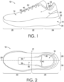
- the footwear article 10 includes at least two primary elements including a sole structure 12 and an upper 14.
- the sole structure 12 When the footwear article 10 is worn (as intended on a foot), the sole structure 12 is typically positioned near the foot plantar surface (i.e., the bottom of the foot).
- the sole structure 12 may protect the bottom of the foot, and in addition, may attenuate ground-reaction forces, absorb energy, provide traction, and control foot motion, such as pronation and supination.
- the upper 14 is coupled to the sole structure 12, and together with the sole structure 12, forms a foot-receiving cavity 16.
- the footwear article 10 may include a forefoot region 20, a midfoot region 22, a heel region 24, and an ankle region 26.
- the forefoot region 20, the midfoot region 22, and the heel region 24 extend through the sole structure 12 and the upper 14.
- the ankle region 26 is located in a portion of the upper 14.
- the forefoot region 20 generally includes portions of the footwear article 10 corresponding with the toes and the joints connecting the metatarsals with the phalanges.
- the midfoot region 22 generally includes portions of the footwear article 10 corresponding with the arch area and instep of the foot.
- the heel region 24 corresponds with rear portions of the foot, including the calcaneus bone.
- the ankle region 26 corresponds with the ankle.
- the footwear article 10 also has a medial side 28 (identified in FIG. 2 and obscured from view in FIG. 1 ) and a lateral side 30 (identified in FIG. 2 and viewable in FIG. 1 ).
- the medial side 28 and the lateral side 30 extend through each of the forefoot region 20, the midfoot region 22, the heel region 24, and the ankle region 26, and correspond with opposite sides of the footwear article 10, each falling on an opposite side of a longitudinal midline reference plane 29 of the footwear article 10, as is understood by those skilled in the art.
- the longitudinal midline reference plane 29 may pass through the foremost point of the sole structure and the rearmost point of the sole structure.
- the medial side 28 is thus considered opposite to the lateral side 30.
- the lateral side corresponds with an outside area of the foot (i.e., the surface that faces away from the other foot), and the medial side corresponds with an inside area of the foot (i.e., the surface that faces toward the other foot).
- the footwear article includes an anterior portion 33 and a posterior portion 35, falling on an opposite side of a latitudinal midline reference plane 31 of the footwear article 10.
- the latitudinal midline reference plane 31 extends perpendicular to the longitudinal midline reference plane 29 and to the ground-surface plane and is spaced evenly between the foremost point of the footwear article 10 and the rearmost point of the footwear article 10.
- these terms may also be used to describe relative positions of different structures. For example, a first structure that is closer to the inside portion of the footwear article might be described as medial to a second structure, which is closer to the outside area and is more lateral.
- the relative terms “inferior” and “superior” may also be used.
- the superior portion generally corresponds with a top portion that is oriented closer towards a person's head when the person's feet are positioned flat on a horizontal ground surface and the person is standing upright
- the inferior portion generally corresponds with a bottom portion oriented farther from a person's head and closer to the ground surface.
- the sole structure 12 may be constructed of various materials and may include various elements.
- the sole structure 12 may include a midsole 32 and an outsole 34.
- the midsole 32 may be formed from a compressible polymer foam element (e.g., a polyurethane or ethylvinylacetate (EVA) foam) that attenuates ground reaction forces (i.e., provides cushioning) when compressed between the foot and the ground during walking, running, or other ambulatory activities.
- EVA ethylvinylacetate
- the midsole 32 may incorporate fluid-filled chambers, plates, moderators, or other elements that further attenuate forces, enhance stability, or influence motions of the foot.
- the midsole 32 may be a single, one-piece midsole, or could be multiple components integrated as a unit.
- the midsole 32 may be integrated with the outsole 34 as a unisole.
- the outsole 34 may be one-piece, or may be several outsole components, and may be formed from a wear-resistant rubber material that may be textured to impart traction and/or may include traction elements such as tread or cleats secured to the midsole 32.
- the outsole 34 may extend either the entire length and width of the sole or only partially across the length and/or width.
- the upper 14 may also be constructed of various materials and may include various features.
- the upper 14 may be constructed of leather, textiles, or other synthetic or natural materials.
- the upper 14 may be a knit textile, woven, braided, non-woven, laminate, or any combination thereof.
- the upper 14 may have various material properties related to breathability, stretch, flexibility, wicking, water resistance, and the like.
- the upper 14 typically includes a portion that overlaps with, and is connected to, the sole structure 12, and the junction of this connection may be referred to as a biteline.
- the upper 14 may include a "strobel,” which includes a material panel extending from the upper 14 and across at least a portion of a foot-facing surface of the sole structure 12, and the strobel may be used to hold the upper 14 on a last when the sole structure 12 is attached to the upper 14.
- the sole structure 12 that is integrated into the footwear article 10 includes a foot-facing surface
- the upper 14 may include a panel (referred to as a strobel) that extends inward from near the biteline region and at least partially covers the foot-facing surface. In that instance, the strobel is positioned underneath a foot when the footwear article is worn.
- the strobel may be covered by an insole or other layer of material.
- the upper 14 includes other features.
- the upper 14 includes an ankle collar 36 that forms a perimeter around at least a portion of the foot-insertion opening 18.
- the upper 14 includes a throat 38 that often extends from the ankle collar 36 and forms a perimeter along at least one or more sides of an elongated opening 40.
- a tongue 42 is located in the elongated opening 40, and a size of the elongated opening 40 can be adjusted using various closure systems.
- FIG. 1 illustrates laces 44, and other closure systems may include elastic bands, hook-and-loop straps, zippers, buckles, and the like.
- the position of the tongue 42 and the connections of the closure system can be adjusted to vary a size of the foot-insertion opening and the elongated opening, such as by making the openings larger when the footwear article is being donned or doffed and by making the openings smaller when the footwear article is being secured onto a foot.
- the tongue 42 might include a tongue reinforcer, which might help the tongue maintain a shape and position when the tongue is subjected to forces or adjustments, such as from other footwear-article elements or from a wearer.
- the footwear article 10 might include an athletic-type shoe, such as might be worn when running or walking, and the description of the footwear article 10, including the elements described with respect to FIGS. 1 and 2 , might also be applicable to other types of shoes, such as basketball shoes, tennis shoes, American football shoes, soccer shoes, leisure or casual shoes, dress shoes, work shoes, a sandal, a slipper, a boot, hiking shoes, and the like.
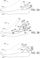
- FIGS. 3A-3C and 4A-4C depict a footwear article 310, which includes an upper 314 coupled to a sole 312, and the upper 314 includes a heel region 324 and an ankle region 326 with an ankle collar 336.
- the ankle collar 336 is movable between a lowered state (as depicted in FIG. 3C ) and a raised state (as depicted in FIGS. 3A and 3B ). In the lowered state, the ankle collar 336 is positioned closer to the sole 312, and in the raised state, the ankle collar 336 is positioned farther from the sole 312.
- the footwear article 410 includes an upper 414 coupled to a sole 412, and the upper 414 includes a heel region 424 and an ankle region 426 with an ankle collar 436.
- the footwear article 310 includes a collar elevator 350 that is coupled to the upper 314 near the heel region 324 and/or the ankle region 326 and that is operable to move the ankle collar 336 from the lowered state to the raised state. More specifically, the collar elevator 350 includes portions that are positioned in the heel region 324 and that extend up into the ankle region 326. As previously, indicated, there are not necessarily precise delineations between the heel region 324 and the ankle region 326; rather, describing the positioning of the collar elevator 350 with respect to these regions is one way to describe that the collar elevator 350 extends from a more inferior part closer to the sole to a more superior part closer to the ankle collar 336.
- the collar elevator 350 may be coupled to the upper in the heel region 324, in the ankle region 326, to the ankle collar 336, or any and all combinations thereof.
- the collar elevator 350 is an example of one type of collar elevator operable to move an ankle collar from the lowered state to the raised state, and as will be described in other portions of this disclosure, a collar elevator may include one or more alternative structures than those depicted in FIGS. 3A-3C . For example, FIGS.
- FIGS. 4A and 4B depict a footwear article 410 with a collar elevator 450 that is operable to move the ankle collar 436 from the lowered state (e.g., FIG. 4C ) to the raised state (e.g., FIGS. 4A and 4B ) and that has a different structure from the collar elevator 350.
- a collar elevator (such as the collar elevators 350 and 450) may include various elements.
- a collar elevator includes a medial lever arm, a lateral lever arm, and a center connecting band that couples the medial lever arm to the lateral lever arm and that is located in a heel portion of the ankle collar.
- each lever arm is affixed to a base, which remains stationary relative to the lever arms as the lever arms deform when the ankle collar is moved to a lowered state.
- the base may be a portion of the footwear article, such as a portion of the sole or a portion of the upper.
- the base may be one or more other anchors affixed directly or indirectly to the sole, the sole itself, or any combination thereof.
- US 9,820,527 describes one or more collar elevators, some of which may be referred to as a deformable member or as deformable members (with or without a base), and the full disclosure of US 9,820,527 is incorporated herein by reference in its entirety.
- at least some of the deformable members described in US 9,820,527 include a medial lever arm, a lateral lever arm, and a center connecting band that couples the medial lever arm to the lateral lever arm.
- US 2018/0110292 and US 2018/0289109 each describes a plurality of other collar elevators, some of which are referred to as a control bar (with or without a base), and the full disclosures of US 2018/0110292 and US 2018/0289109 are incorporated herein by reference in their entirety.
- at least some of the control bars described in US 2018/0110292 and US 2018/0289109 include a medial lever arm, a lateral lever arm, and a center connecting band that couples the medial lever arm to the lateral lever arm.
- Each of the illustrated collar elevators 350 and 450 depicts examples of medial lever arms 352 and 452, respectively.
- each of the illustrated collar elevators 350 and 450 depicts examples of lateral lever arms 354 and 454, respectively, and center connecting bands 356 and 456, respectively.
- the lever arms 352 and 354 attach to a base 358
- the lever arms 452 and 454 attach to a base 458 having a different structure from the base 358.
- the base 358 is affixed to or near a foot-facing surface of the sole 312, and the base 358 might be a portion of an outsole, a portion of a midsole, a portion of an insole, a portion of a strobel, a plate or sheet of material layered between any of these sole layers, or any combination thereof.
- the base 358 might include a rigid portion or section to which the lever arms 352 and 354 are anchored. As depicted in FIG. 3B , the base 358 partially covers a superior surface of the sole 312, and the superior surface faces towards the foot-receiving cavity 316.
- the sole 312 includes a midsole, such that the superior surface is of the midsole and the base 358 is layered between the midsole and an insole.
- a surface forefoot portion 360 and a surface heel portion 362 are identified, both of which are not covered by the base 358.
- the base 358 includes a forward anterior edge 364 and a rearward posterior edge 366, both of which extend from the medial side to the lateral side of the footwear article 310.
- the rearward posterior edge 366 is positioned closer to a rearmost point 368 of the surface heel portion 362 (as compared to the forward anterior edge 364) and is also spaced forward of the rearmost point 368.
- FIGS. 4A-4C depict a different aspect, in which the base 458 might attach to a portion of the upper (e.g., a heel counter), a portion of the midsole sidewall, or any combination thereof, and the base 458 wraps around a backside of the footwear article, as opposed to extending through the footbed in the manner described with respect to the base 358.
- the base 458 might attach to a portion of the upper (e.g., a heel counter), a portion of the midsole sidewall, or any combination thereof, and the base 458 wraps around a backside of the footwear article, as opposed to extending through the footbed in the manner described with respect to the base 358.
- the medial lever arm, the lateral lever arm, and the center connecting band may be a single continuous body, such that clear demarcation may not exist between the medial lever arm, the lateral lever arm, and the center connecting band.
- the medial and lateral arms and the center connecting band may be molded, cast, 3D printed, or otherwise formed as a single, integrally formed unit.
- the medial lever arm and the lateral lever arm may be discrete, separate, and distinct elongated members, which are connected to the center connecting band, such as by a mechanical or chemical coupling, a friction fit, sheathing, or other coupling.
- the collar elevator moves the ankle collar from the lowered state to the raised state. More specifically, at least a portion of the medial lever arm, the lateral lever arm, the center connecting band, or any combination thereof, is affixed to a portion of the upper.
- the center connecting band may be affixed near a heel portion of the ankle collar.
- the center connecting band may be attached to the heel portion of the ankle collar by an adhesive, connection tab, heat stake, stitch, and the like.
- the collar elevator stores potential energy by elastically deforming from a less compressed configuration (e.g., FIGS. 3A and 4A ) to a more compressed configuration (e.g., FIGS. 3C and 4C ) when an applied force moves the ankle collar from the raised state to the lowered state.
- the potential energy returns the collar elevator to the less compressed configuration upon removal of the applied force, and since the collar elevator is affixed to the upper, the ankle collar is also moved from the lowered state to the raised state.
- While the compression of the collar elevator may be greater when the ankle collar is moved to the lowered state (as compared with the raised state), in the raised state the collar elevator may still store potential energy in an at least partially deformed state (i.e., preloaded compression) so as to be able to hold a rear, heel portion of the ankle collar about the heel of the wearer.
- preloaded compression potential energy in an at least partially deformed state
- portions of the upper may hold or retain the collar elevator in the preloaded configuration when the ankle collar is in the raised state.
- the collar elevator may be unloaded when the ankle collar is in the raised state.
- the portion 325 or 425 of the upper below the center connecting band may include wall of one or more textiles that are more flexible than other portions of the upper.
- This more flexible region of the upper may, for example, be at least partially in the heel-counter region.
- this more flexible portion 325 or 425 of the upper may collapse more easily when the ankle collar is moved to a lower state and may provide less resistance for the collar elevator (as compared with a less flexible upper in other parts of the footwear article or in a typical footwear article) when the collar elevator is returning to the less compressed state.
- the combination of the medial lever arm, the lateral lever arm, and the center connecting band may be referred to as a deformable element.
- deformable element refers to a resiliently flexible member that can be bent or compressed but has a bias to move towards a non-bent or uncompressed state.
- the deformable element may include a single, integrally formed, deformable element, extending continuously from the medial lever arm to the lateral lever arm.
- the medial lever arm and the lateral lever arm may be two or more separate and distinct deformable elements that connect to the center connecting band, which may also be referred to as a heel piece.
- the deformable element might be directly coupled, mounted, or attached to the base.
- the base may include one or more anchors that engage and retain the deformable element in place.
- anchors may be located at a junction (e.g., 359 and 459) between the lever arms and the base.
- Such anchors might be integrally formed with, coupled to, and/or located within or between or outside of portions of the sole (e.g., insole, midsole, outsole).
- an anchor may be disposed in a block, plate, or wedge layered among, on top, or beneath the sole.
- a portion of the sole e.g., midsole
- a portion of the sole e.g., midsole
- a base extending in the mediolateral orientation includes an anchor-shaped receptacle into which an anchor engages by way of a resistance fit, compression fit, a snap fit, or via an interlocking mechanism/configuration.
- the anchors may be integrally formed with, coupled to, and/or located within, between, or outside of portions of the upper.
- anchors may be located in the upper, in a heel counter, or any combination thereof.
- a single anchor may extend a full width of the footwear article, or two anchors may be positioned on opposing sides of the footwear article (e.g., on the medial and lateral sides).
- the deformable member may attach to the base or to an anchor at an angle.
- the deformable member might attach at a perpendicular angle to the base and then curve or arc rearwardly.
- the deformable member might attach at a forwardly inclining angle (i.e., upwards and forwards) or a rearwardly reclining angle (i.e., upwards and rearwards) before rearwardly arcing.
- a connection between the deformable member and the base or the anchors may be described in various manners.
- the deformable element does not pivot (i.e., is non-pivoting) about the base (e.g., about an insole, midsole, or outsole).
- the deformable element may be non-rotatably coupled to the base.
- engagement between the deformable element and the base (or anchor) is free of play, meaning that there is little or no relative movement between the two components.
- a deformable element may include one or more of a tube, a wire, a spring, a shape memory structure or material, and the like.
- a deformable element can include one or more materials such as carbon steel, stainless steel, titanium, nickel titanium (nitinol) and other metals and alloys (shape-memory or otherwise), polymers (shape-memory or otherwise), composite materials, foam materials, graphite, carbon fiber, fiberglass, TPC-ET, silicone, TPU, and polycarbonate.
- a deformable element might include titanium or be a titanium wire.
- one or more deformable elements might be made of a first material, e.g., titanium, and one or more additional deformable elements might be made of a second material, e.g., graphite.
- the deformable element might include a single, unitary piece.
- a first end of the deformable element e.g., an end of the medial lever arm
- a second end of the deformable element e.g., an end of the lateral lever arm
- a middle portion of the deformable element e.g., the center connecting band
- the deformable element might include a plurality of separate and distinct components.
- a deformable element might include two separate components, with a first component (e.g., medial lever arm) having a first end embedded in or attached to a medial anchor and a second end embedded in or attached to the medial side of a heel piece or center connecting band.
- a second component e.g., lateral lever arm
- a first component e.g., medial lever arm
- a second component e.g., lateral lever arm
- the plurality of separate and distinct components can be secured together, for example, with one or more of a tape wrap, woven encasing, overmold (e.g., TPU), heat shrink tube, and the like, each of which can provide different stabilities and strengths.
- a deformable element might include one or more wires encased independently or encased together in a cover, sleeve, overmold, or heat shrink tube.
- the one or more wires can arch, bend, and sway and then return to an initial/normal state in order to help facilitate the elastic deformation of the deformable element.
- a deformable element might have variable mechanical properties along its length and/or at distinct points along its length. Such variation might be provided by the deformable element (e.g., by a wire or bundle of two or more wires), by a securement surrounding all or a portion of the deformable element(s), or any combination thereof.
- the deformable element and/or the securement might have a variable cross-section, a variable density, a variable material, and/or the like along its length.
- a variable cross-section in turn, can be provided by variation in thickness or shape, or twisting of the deformable element otherwise having a constant thickness or shape along its length.
- a deformable element may include a cover, sleeve, overmold, or other suitable structure, which might protect other elements (e.g., wire, spring, etc.) of the deformable element and might control, guide, support and/or otherwise affect the flexure or compression of the deformable element.
- the cover based on its material of manufacture, shape, geometry, etc., is configured to facilitate mechanical stress distribution by transferring mechanical bending/deforming forces from the deformable element (e.g., from the wire(s) or spring) to the cover to prevent, or at least inhibit, the deformable element from damage or breakage that may otherwise result from the concentrated and repeated mechanical stress experienced by the deformable element.
- the cover may have dimensions that vary along its length, such as a funnel-like tapering shape, to help distribute stress and contribute to the dynamic flexing of the deformable element.
- the cover might still provide at least some degree of bias, thereby still helping to move the ankle collar from the lowered position to the raised position.
- the cover may provide additional padding and/or support to the deformable element and may prevent, or at least inhibit, a wearer from feeling the deformable element.
- the center connecting band may also be referred to as a heel piece.
- the center connecting band may be integrally formed with the medial and lateral lever arms, as a single, continuous unit.
- the center connecting band may be a separate piece that extends between, and bridges, the medial and lateral lever arms.
- the center connecting band may provide a coupling to the upper and may provide a frame to the ankle collar, to inhibit the ankle collar from collapsing into the foot-receiving opening when a foot is being inserted.
- a footwear article with a collar elevator (e.g., collar elevators 350 and 450) might be slipped on by the wearer without the wearer using his or her hands to manipulate the footwear article.
- the wearer's toes may be inserted through the foot-insertion openings 318 or 418, while the arch or heel of his or her foot is used to press downward on the ankle collars 336 or 436 towards the soles 312 or 412.
- This adjustment of the ankle collar 336 or 436 into the lowered state closer to the sole may increase a size of the foot-insertion opening 318 or 418.
- the collar elevator 350 or 450 moves the ankle collar from the lowered state (i.e., FIGS. 3C and 4C ) to the raised state (i.e., FIGS. 3A and 4A ) to help secure the footwear article to the wearer's foot.
- the collar elevators 350 and 450 may reduce potential structural breakdown of the upper heel region and upper ankle region over time, which could result from repeated hands-free donning, by providing a frame operational to return to, or bias in, the raised state. Furthermore, the collar elevators 350 and 450 may allow the user to more easily don (i.e., put on) his or her shoes without the use of hands and/or without having to bend down to tie the laces, without having to use a shoe horn, or without using other such adjustment features, elements, or mechanisms for fit. Moreover, the footwear articles 310 and 410 may more easily receive, or more easily direct a wearer's foot into, or otherwise accommodate, a wearer's foot with respect to, the foot-receiving opening. This potentially easier donning may result from, among other things, the collar elevators 350 and 450 helping to provide a larger foot-insertion opening without allowing a topline of the ankle collar to fold inward towards the foot-receiving cavity.
- the ankle collars 336 and 436 may be elastic or may include a goring element that permits expansion of the foot-insertion openings 318 and 418, such as when the ankle collar is moved to a lowered state.
- the foot-insertion openings 318 and 418 may be expanded by at least about 5%, or at least about 10%, or at least about 15%.
- This measured expansion may be detected in various manners. For example, a first circumference of the foot-insertion opening may be measured when the ankle collar is in a first state, and a second circumference may be measured when the ankle collar is in a second state, which is closer to the sole (relative to the first state).
- the distance of the ankle collar from the sole in the first and second states may be measured in a vertical plane (i.e., perpendicular relative to the horizontal reference plane, including a flat ground surface on which the ground-contacting surface sits in an at-rest position), and the distance may be measured from a rearmost point of the ankle collar topline edge to a topline edge of the sole (e.g., where the sole connects to the upper at the biteline).
- the distance in the first state will be longer than the distance in the second state, and in one aspect, the second distance is equal to or shorter than 75% of the first distance.
- the circumference in the second state having the distance equal to or shorter than 75% of the distance in the first state, the circumference may be expanded by at least about 5%, or at least about 10%, or at least about 15%.
- a circumference of the foot-insertion openings 318 and 418 may be expandable by at least about 1.0 inch (about 2.54 centimeters), when the ankle collar is in the second state having the distance equal to or shorter than 75% of the distance in the first state.
- An amount of the expansion of the foot-insertion opening 318 and 418 may vary with the shoe style and size.
- a height of the ankle collars 336 and 436 above the soles 312 and 412 in the lowered state is about 50% lower than the height in the raised state, however, as with other parameters, this may vary depending on the shoe style and size.
- the collar elevators 350 and 450 provide a return force when moving the ankle collars 336 and 436 from the lowered state to the raised state.
- the return force is between about 1 pound-force and about 15 pound-force, and this may be measured at various positions of the ankle collar.
- the ankle collar may include a first state having a first distance from the sole and a second state having a second distance from the sole, which is shorter than the distance in the first state.
- the collar elevators 350 and 450 provide the return force between about 1 pound-force and about 15 pound-force in the second state having the distance equal to or shorter than about 85% of the distance in the first state.
- the collar elevators 350 and 450 provide the return force between about 1 pound-force and about 15 pound-force in the second state having the distance equal to or shorter than about 75% of the distance in the first state. Further still, the collar elevators 350 and 450 might provide the return force between about 1 pound-force and about 15 pound-force in the second state having the distance equal to or shorter than about 50% of the distance in the first state.
- the return force may be strong enough such that the rear of the ankle collar rebounds back up from the second state and snugly fits around the wearer's heel.
- the ankle collars 336 and 436 may be elevated from the lowered state to the raised state in less than about 1 second, when the distance between the ankle collar and the sole in the lowered state is shorter than 85%, or shorter than 75%, or shorter than 50% of the distance in the raised state.
- ankle collars 336 and 436 may be elevated from the lowered state to the raised state in less than about 0.5 seconds, when the distance between the ankle collar and the sole in the lowered state is shorter than 85%, or shorter than 75%, or shorter than 50% of the distance in the raised state.
- the ankle collars 336 and 436 may be elevated from the lowered state to the raised state in less than about 0.2 seconds, when the distance between the ankle collar and the sole in the lowered state is shorter than 85%, or shorter than 75%, or shorter than 50% of the distance in the raised state. This rebound time is measured absent any counteracting external forces, such as friction that might be imparted by the wearer's heel.
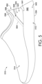
- FIGS. 5-7 another footwear article 510 is described having an upper 514 coupled to a sole 512, and FIG. 5 depicts a lateral side of the footwear article 510.
- the upper 514 includes a heel region 524 and an ankle region 526 having an ankle collar 536.
- the ankle collar 536 is movable between a lowered state (e.g., FIG. 6 ) positioned closer to the sole 512 and a raised state (e.g., FIG. 5 ) positioned farther from the sole 512.
- the footwear article 510 includes a collar elevator 550 coupled to the heel region 524 of the upper, to the ankle region 526 of the upper, near or to the ankle collar 536, or to any combination thereof, and operable to move the ankle collar 536 from the lowered state to the raised state.
- the center connecting band 556 may be affixed to (or near) the rear portion of the ankle collar 536, and/or the lever arms 552 and 554 may be affixed to the heel region 524 of the upper.
- the collar elevator 550 that is illustrated in FIGS. 5 and 6 is an example of one type of collar elevator, and in other aspects of this disclosure, the footwear article 510 may include any of a variety of other collar elevators disclosed in this specification.
- the upper 514 is tongue-less, such that the vamp extends all the way from the forefoot region up to the front, topline edge of the ankle collar 536.
- the upper 514 might include a throat (e.g., 38), a tongue (e.g., 42), and a closure system (such as hook-and-loop straps, elastic bands, laces 44, and the like).
- the sole 512 includes a sidewall 540.
- the sidewall 540 is a surface of the sole that extends around at least a portion of the sole perimeter. Typically, a sidewall extends from a more superior portion near the upper (e.g., portion 541 near the top edge of the sole that joins with the upper at a biteline) to a more inferior portion that is closer the ground-contacting surface (e.g., portion 543).
- the sidewall 540 may gradually transition to a ground-contacting surface with a more rounded corner at the junction between the sidewall and ground-contacting surface. In other instances, the transition from the sidewall to a ground-contacting surface may be less gradual and represented by a sharper corner edge at the transition.
- a footwear article includes a midsole (e.g., foam midsole) then at least a portion of the sidewall is often formed by the midsole.
- the sidewall may also be formed by a cupsole or by a perimeter edge of an outsole.
- the sidewall 540 in FIG. 5 is relatively flat with little to no surface changes.
- a sidewall may include various curvatures, slope changes, indentions, dimples, nodes, protrusions, recesses, grooves, ribs, sipes, and the like.
- the footwear article 510 includes a collar elevator 550.
- the collar elevator 550 includes a center connecting band 556 located in or near a rear portion of the ankle collar 536.
- FIG. 8 a cross-sectional view is illustrated, taken along the longitudinal midline reference plane 529.
- the longitudinal midline reference plane extends in a generally vertical orientation (perpendicular to a ground surface on which the ground-contacting surface is resting), and passes through the rearmost point of the footwear article 510 and the foremost point of the footwear article.
- the center connecting band 556 includes a forwardly inclined angle 560, relative to a horizontal reference plane 562 when the ankle collar 536 is in the raised state.
- the horizontal reference plane 562 generally includes the plane of a relatively flat ground surface on which the ground-contacting surface rests with the footwear article being stationary, in an at-rest state.
- the forwardly inclined angle 560 might be determined in various manners, based on a configuration of the center connecting band 556.
- FIG. 8 depicts a cross section of the center connecting band 556, and a zoomed-in view 10B is provided to more easily view a cross-sectional, 2D form or shape of the center connecting band 556.
- the 2D form is illustrated as being either rectangular with curved corners, ovular, or an elongated pill-shaped.
- the center connecting band 556 includes a length 568 extending from a first endpoint 570 along the longitudinal orientation to a second endpoint 572 along the longitudinal orientation.
- the 2D form in FIG. 8 is representative of one aspect of the disclosure, and in other aspects, the 2D form may have various shapes.
- FIG. 9 a plurality of alternative cross-sectional, 2D forms are illustrated, and a cross section of the center connecting band might alternatively include one or more of these 2D forms. It should be noted that relative directional references “anterior” and “posterior” have been positioned in FIG. 9 to correspond with respective directions in the footwear article 510.
- FIG. 9 is organized into groups of cross-sectional 2D forms that might be included in alternative aspects of the center connecting band.
- group A represents center connecting bands that might include a single solid body.
- Group B represents center connecting bands that might include an anterior layer or wall and a posterior layer or wall, possibly with a space in between.
- B 1 includes an anterior layer and a posterior layer affixed to one another without any space therebetween, and B2 and B3 each includes a space.
- Group C includes center connecting bands having a plurality of discrete elongated members (in the medial to lateral direction), such as slats, which may be disconnected from one another and spaced apart, at least within the region of the center connecting band.
- Group D includes center connecting bands having discrete bridges and/or necks that extend between, and connect to, paddles or other support structures within the center connecting bands.
- reference numeral 556B identifies a lateral side paddle.
- the angle reference line 564 may be measured along a longitudinal reference axis that bisects the cross-sectional 2D form(s) into substantially symmetrical mirror images.
- each example 2D form in Groups A-D is illustrated to include a respective longitudinal reference axis that bisects the cross-sectional 2D form into substantially symmetrical mirror images and that might be used to determine the angle reference line 564 in a center connecting band including a cross section having that particular 2D form.
- the cross-sectional 2D form of a center connecting member may not be symmetrical on opposing sides of a bisecting, longitudinal reference axis, such that the method described above would not apply.
- the cross-sectional 2D form may present other features that could be usable to determine an angle reference line.
- the cross-sectional 2D form may include a convex anterior surface 556C, in which case a tangent line 564B positioned at an arc midpoint 565 may be used to determine the angle reference line.
- the cross-sectional 2D form may include a concave anterior surface, in which case the angle reference line may extend through the arc endpoints.
- the angle reference line might be based on a relatively straight and flat anterior surface of the 2D form.
- the 2D form of the cross-sectional view includes a relatively flat and straight anterior surface 556D.
- the 2D form in group G includes a length 568 extending from first endpoint 570 along the longitudinal orientation to a second endpoint 572 along the longitudinal orientation.
- the angle reference line may be established along (i.e., parallel and collinear with) the anterior surface 556D when a flat portion of the anterior surface includes a straight-surface height 574 that is equal to or greater than 50% of the center-connecting-band length 568.
- the angle reference line 564 may be positioned along a reference line that is evenly spaced between a superior most point of the 2D form and an anterior most point of the 2D form and between an inferior most point and a posterior most point. If there are more than one superior most points, then the superior most point that is the most anterior (compared with the other superior most points) is selected, and if there are more than one anterior most points, then the anterior point that is most superior is selected. Likewise, if there are more than one inferior most points, then the inferior most point that is also the most posterior is selected, and if there are more than one posterior most points, then the posterior point that is most inferior is selected.
- the angle reference line that provides the smallest angle is selected to determine the forwardly inclined angle 560.
- the forwardly inclined angle 560 contributes to one or more operations of the footwear article in various manners.
- a center connecting band having a smaller forwardly inclined angle may provide a larger overhanging catch surface, which can impede a wearer's foot from slipping relative to a heel portion of the footwear article.
- an inner lining material e.g., 526B in FIG. 8
- the center connecting band can still provide a rigid backing to impede heel slippage out of the foot-insertion opening.
- a center connecting band having a forwardly inclined angle may also impede removal of the footwear article, such as when the wearer attempts to pull his or her foot from the footwear article.
- a wearer's heel may catch on the heel portion or rear ankle collar, which is supported by the center connecting band, when the wearer attempts to slide his or her foot from the foot-insertion opening.
- the interaction between the foot and the center connecting band generates forces having vectors that are substantially perpendicular to the angle reference line, and an example of the vector of the force generated by the center connecting band's resistance is identified by arrow "A" in FIG. 10 .
- a vector of the foot's force on the center connecting band is in the opposite direction to the arrow A and is represented by arrow B, since the force vector is influenced by the forward incline of the center connecting band.
- the heel-counter region 525 may include a more flexible wall, which can also permit rearward travel of a wearer's heel when slipping the heel out of the foot-insertion opening, and this rearward travel may contribute to the wearer's heel catching on the center connecting band.
- the term "doffing" generally describes the act of taking off a footwear article.
- a wearer might dig his/her toes, or the ball of his/her foot, into the footbed to gain traction for pulling his/her heel past the center connecting band. Alternatively (or additionally) the wearer might change or alter a path along which the wearer pulls his/her heel to move around and bypass the center connecting band. Moreover, the wearer might have to use his or her hands to assist with doffing the shoe. Further still, to remove the shoe of a left foot, the wearer might have to step with his/her right foot onto the heel counter of the left shoe, which can cause the upper materials to delaminate, pull away from the sole, or otherwise breakdown.
- an aspect of this disclosure includes a doffing ledge that is in a heel portion of the sole, and the doffing ledge provides a surface against which a wearer can depress with his or her opposing foot to assist with removing the footwear article (see e.g., FIG. 10 ).
- a doffing ledge 580 is formed by the sidewall of the footwear article 510.
- the doffing ledge 580 protrudes outwardly from a doffing-ledge first portion 582 closer to the upper 514 to a doffing-ledge second portion 584 farther from the upper 514.
- the doffing ledge comprises a doffing surface 586 that declines at a doffing angle 588 as it extends from the doffing-ledge first portion 582 to the doffing-ledge second portion 584. Similar to the forwardly inclined angle 560, the doffing angle 588 is relative to the horizontal reference plane 562. Further, in one aspect, the doffing-angle reference line 589 extends collinear and parallel with the doffing surface 586.
- the doffing ledge 580 provides one example, and in accordance with an aspect of this disclosure, one or more doffing ledges may be positioned at one or more locations along the sidewall 540.
- the doffing ledge 580 is substantially aligned with a longitudinal midline reference plane 529 (identified in FIG. 7 ), and in other aspects, the doffing surface may extend along a medial side 537 of the heel region (see e.g., FIG. 7 ), along a lateral side 539 of the heel region, along a medial-to-lateral transverse portion 535 of the heel region, or any and all combinations thereof.
- the sidewall 540 and the doffing surface 586 may continuously wrap from the medial side 537 to the transverse portion 535, from the lateral side 539 to the transverse portion 535, or all the way from the medial side 537 to the lateral side 539.
- another doffing ledge 580B is formed by the sidewall of the footwear article 510 on the medial side 537 of the heel region.
- a position on the medial side 537 may provide some differences over the position of the doffing ledge 580, which is more in the transverse portion 535, aligned with the longitudinal midline reference plane.
- a position on the medial side 537 might be conducive to engagement with the medial side of the footwear article on the opposing foot with the medial portion or ball of the opposing foot.
- another doffing ledge 580C might be formed by the sidewall of the footwear article 510 on the lateral side 539 of the heel region.
- a position on the lateral side 539 may provide some differences over the position of the other doffing ledges 580 and 580B.
- a position on the lateral side 539 might be conducive to engagement with the lateral side of the footwear article on the opposing foot or with the lateral portion of the opposing foot.
- the doffing ledges 580, 580B, and 580C might be considered a single doffing ledge with different regions or portions at different locations of the sidewall 540.
- the doffing ledge 580B protrudes outwardly from a doffing-ledge first portion 582B closer to the upper 514 to a doffing-ledge second portion 584B farther from the upper 514.
- the doffing ledge 580B comprises a doffing surface 586B that declines at a doffing angle 588B as it extends from the doffing-ledge first portion 582B to the doffing-ledge second portion 584B. Similar to the forwardly inclined angle 560, the doffing angle 588B is relative to the horizontal reference plane 562.
- the doffing-angle reference line 589B extends collinear and parallel with the doffing surface 586.
- a cross-sectional view of the doffing ledge 580C is not explicitly provided in this disclosure, it is understood that the doffing ledge 580C, as well as any other doffing ledge in accordance with this disclosure, protrudes outwardly from a doffing-ledge first portion closer to the upper to a doffing-ledge second portion farther from the upper, the doffing ledge having a doffing surface that declines from the doffing-ledge first portion to the doffing-ledge second portion at a doffing angle.
- the operability of the doffing ledges (e.g., 580, 580B, and 580C) to assist with removing a shoe (e.g., in a hands-free manner) depends at least in part on a size of the doffing angle relative to the forwardly inclined angle 560.
- the doffing angle is less than the forwardly inclined angle 560.
- the force applied to a doffing ledge with a smaller doffing angle (i.e., approaching horizontal and parallel with the horizontal reference plane 562) will be directed more vertically downward than a doffing ledge with a higher doffing angle.
- the force vector C is more vertically oriented than the force vector B, which can assist the wearer with overcoming the force of the center connecting band when removing the footwear article.
- the doffing ledge 580B is not necessarily vertically aligned with the center connecting band 556, the operability of the doffing ledge 580B might still be configured based on the forwardly inclined angle 560.
- the doffing angle 588B (in FIG. 11 ) of the doffing ledge 580B positioned on the medial side 537 is less than the forwardly inclined angle 560 (in FIG. 8 ).
- the forwardly inclined angle 560 of the center connecting band is in a first range of 45 degrees to 70 degrees, and the forwardly inclined angle within this range might be included in a footwear article for various reasons.
- the forwardly inclined angle within this first range might be selected to provide some additional heel-securing functionality (i.e., impede heel slippage and snug up against the wearer's heel while the footwear is being worn).
- the forwardly inclined angle within this first range might provide a desired esthetic contour in a rear portion of the ankle region or ankle collar.
- the forwardly inclined angle 560 of the center connecting band is in a second range of 50 degrees to 65 degrees, and as compared with the first range, this second range omits some angles that might not provide sufficient heel security and omits other angles that might provide too much resistance to doffing.
- the forwardly inclined angle may be in a range of 52 degrees to 62 degrees.
- the forwardly inclined angle 560 is in the first range of 45 degrees to 70 degrees and the doffing angle is equal to or less than the forwardly inclined angle and is in a third range of 30 degrees to 70 degrees.
- the third range for the doffing angle may extend to smaller degrees, as compared with the range for the forwardly inclined angle, since it might be desirable to select doffing angles that are several degrees less than the forwardly inclined angle. For example, if a forwardly inclined angle 560 is 45 degrees, then it may be desirable for a doffing ledge to have a doffing angle of 30 degrees to create enough leverage on the doffing ledge to hold the footwear article in position while attempting to pull a foot out.
- the doffing angle is equal to or less than the forwardly inclined angle
- the doffing angle may be in a fourth range of about 40 degrees to about 60 degrees, and as compared with the third range, this second range omits some larger angles that might not provide sufficient leverage and omits some smaller angles that may generate surfaces jutting too far outward from a sidewall.
- the doffing angle may be in a fourth range of about 45 degrees to about 55 degrees.
- the doffing surface (e.g., 586 and 586B) includes a length 590 that is measured along a substantially flat portion of the doffing surface (in the vertical reference plane) and that satisfies a minimum length threshold.
- the doffing-surface length 590 might be at least 75 percent of the center-connecting-band length 568.
- the doffing-surface length 590 might be at least 90 percent of the center-connecting-band length 568.
- the doffing-surface length 590 might be at least as long as the center-connecting-band length 568.
- the doffing-surface length 590 might be at least 130 percent (e.g., one and one-third is at least 130%) of the center-connecting-band length 568. In an alternative aspect, the doffing-surface length 590 is at least 150 percent (i.e., one and one-half) of the center-connecting-band length 568.
- the minimum length threshold might be based on other standards as well.
- the doffing-surface length 590 might be at least one-third of the sole height 592, which extends from a superior-most point of the sole (in the vertical reference plane) to the horizontal reference plane (as defined in other portions of this disclosure).
- the doffing-surface length 590 is at least 50 percent of the sole height. In a further aspect, the doffing-surface-length 590 is at least 75 percent of the sole height. In yet another aspect, the doffing-surface length 590 is equal to or greater than the sole height.
- an exemplary clause 4 may indicate the method/apparatus of any of clauses 1 through 3, which is intended to be interpreted such that features of clause 1 and clause 4 may be combined, elements of clause 2 and clause 4 may be combined, elements of clause 3 and 4 may be combined, elements of clauses 1, 2, and 4 may be combined, elements of clauses 2, 3, and 4 may be combined, elements of clauses 1, 2, 3, and 4 may be combined, and/or other variations.
- the terminology “any of clauses” or similar variations of said terminology is intended to include “any one of clauses” or other variations of such terminology, as indicated by some of the examples provided above.
- a footwear article comprising: a sole having a ground-contacting surface and a sidewall; an upper coupled to the sole and comprising an ankle collar that is movable between a lowered state positioned closer to the sole and a raised state positioned farther from the sole; a collar elevator operable to return the ankle collar from the lowered state to the raised state, the collar elevator having a medial lever arm, a lateral lever arm, and a center connecting band that couples the medial lever arm to the lateral lever arm and that is located near a rear portion of the ankle collar, wherein the center connecting band comprises a forwardly inclined angle equal to or less than 65 degrees relative to a horizontal reference plane when the ankle collar is in the raised state; and the sidewall comprising a doffing ledge that is in a heel portion of the sole and that protrudes outwardly from a doffing-ledge first portion closer to the upper to a doffing-ledge second portion farther from the upper, wherein the doffing ledge comprises a doffing surface
- Clause 7 The apparatus of any of the clauses, wherein the doffing surface is aligned with a midline reference plane, which passes through a rearmost point and a foremost point of the footwear article.
- Clause 8 The apparatus of any of the clauses, wherein the doffing ledge is positioned on a lateral side of the sole of the footwear article.
- the doffing surface comprises a doffing-surface length extending from the doffing-ledge first portion to the doffing-ledge second portion; wherein at the doffing ledge the sole includes a sole height; and wherein the doffing-surface length is equal to or larger than one-half of the sole height.
- a footwear article comprising: a sole having a ground-contacting surface and a sidewall; an upper coupled to the sole and comprising an ankle collar that is movable between a lowered state positioned closer to the sole and a raised state positioned farther from the sole; a collar elevator operable to return the ankle collar from the lowered state to the raised state, the collar elevator having a medial lever arm, a lateral lever arm, and a center connecting band that couples the medial lever arm to the lateral lever arm and that is located near a rear portion of the ankle collar, wherein the center connecting band comprises a forwardly inclined angle in a range of 70 degrees to 45 degrees relative to a horizontal reference plane when the ankle collar is in the raised state; and the sidewall comprising a doffing ledge that is in a heel portion of the sole and that protrudes outwardly from a doffing-ledge first portion closer to the upper to a doffing-ledge second portion farther from the upper, wherein the doffing ledge comprises a doffing
- Clause 14 The apparatus of any of the clauses, wherein the forwardly inclined angle is in a range of 52 degrees to 62 degrees.
- Clause 16 The apparatus of any of the clauses, wherein the doffing angle is in a range between 40 degrees and 60 degrees.
- a footwear article comprising: a sole having a ground-contacting surface and a sidewall; an upper coupled to the sole and comprising an ankle collar that is movable between a lowered state positioned closer to the sole and a raised state positioned farther from the sole; a collar elevator operable to return the ankle collar from the lowered state to the raised state, the collar elevator having a medial lever arm, a lateral lever arm, and a center connecting band that couples the medial lever arm to the lateral lever arm and that is located near a rear portion of the ankle collar, wherein the center connecting band comprises a forwardly inclined angle equal to or less than 65 degrees relative to a horizontal reference plane when the ankle collar is in the raised state, and wherein the center connecting band includes a length extending from a first endpoint along a longitudinal orientation to a second endpoint along the longitudinal orientation; and the sidewall comprising a doffing ledge that is in a heel portion of the sole and that protrudes outwardly from a doffing-ledge first portion closer to
- Clause 21 The footwear article of any of clauses 1 through 20, wherein the sole includes a superior surface facing the foot-receiving cavity, a lateral edge, and a medial edge; wherein the base includes a forward terminal edge and a posterior terminal edge; wherein the forward terminal edge and the posterior terminal edge each begins at the lateral edge of the sole, extends across the superior surface of the sole, and terminates at the medial edge of the sole; and wherein the terminal posterior edge is spaced forwardly of a rearmost point of the superior surface.
Landscapes
- Health & Medical Sciences (AREA)
- General Health & Medical Sciences (AREA)
- Physical Education & Sports Medicine (AREA)
- Footwear And Its Accessory, Manufacturing Method And Apparatuses (AREA)
Abstract
Description
- This disclosure relates to a footwear article having doffing ledge.
- Some footwear articles include an ankle collar that is manipulated when the footwear article is put on. For example, the ankle collar may be depressed towards the sole as the wearer's foot is slid into the upper. Furthermore, some of these footwear articles include a collar elevator operable to move the ankle collar from the depressed or lowered state to the raised state. An example of one type of collar elevator is described in
US Pat. No. 9,820,527 US Pat. Pub. 2018/0110292 andUS Pat. Pub. 2018/0289109 . - Some subject matter described in this disclosure makes reference to drawing figures, which are incorporated herein by reference in their entirety.
-
FIG. 1 depicts a side view of a footwear article in accordance with an aspect of this disclosure. -
FIG. 2 depicts a top view of the footwear article ofFIG. 1 in accordance with an aspect of this disclosure. -
FIGS. 3A-3C depict another footwear article having a collar elevator in accordance with an aspect of this disclosure. -
FIGS. 4A-4C depict another footwear article having an alternative collar elevator in accordance with an aspect of this disclosure. -
FIG. 5 depicts another footwear article in accordance with an aspect of this disclosure. -
FIG. 6 depicts the footwear article ofFIG. 5 with the ankle collar in a lowered state in accordance with an aspect of this disclosure. -
FIG. 7 depicts a top view of the footwear article ofFIG. 5 in accordance with an aspect of this disclosure. -
FIG. 8 depicts a cross-sectional view of the footwear article ofFIG. 5 in accordance with an aspect of this disclosure. -
FIGS. 9A-9G depict alternative center connecting bands in accordance with an aspect of this disclosure. -
FIG. 10 depicts doffing of a footwear article in accordance with an aspect of this disclosure. -
FIG. 11 depicts another doffing ledge in accordance with an aspect of this disclosure. - Subject matter is described throughout this Specification in detail and with specificity in order to meet statutory requirements. The aspects described throughout this Specification are intended to be illustrative rather than restrictive, and the description itself is not intended necessarily to limit the scope of the claims. Rather, the claimed subject matter might be practiced in other ways to include different elements or combinations of elements that are equivalent to the ones described in this Specification and that are in conjunction with other present technologies or future technologies. Upon reading the present disclosure, alternative aspects may become apparent to ordinary skilled artisans that practice in areas relevant to the described aspects, without departing from the scope of this disclosure. It will be understood that certain features and subcombinations are of utility and may be employed without reference to other features and subcombinations. This is contemplated by, and is within the scope of, the claims.
- The subject matter described in this Specification generally relates to, among other things, a footwear article having a doffing ledge, including manufactures, machines, and methods associated therewith. In some aspects, the doffing ledge may provide a lever for pressing the footwear article in one direction, while the wearer slides his or her heel out of the footwear article in a different direction. Some aspects of this disclosure are directed to a footwear article with a doffing ledge and a collar elevator.
- Before describing the figures in more detail, some additional explanation will now be provided related to certain terminology that may be used in this disclosure.
- "A," "an," "the," "at least one," and "one or more" might be used interchangeably to indicate that at least one of the items is present. When such terminology is used, a plurality of such items might be present unless the context clearly indicates otherwise. All numerical values of parameters (e.g., of quantities or conditions) in this specification, unless otherwise indicated expressly or clearly in view of the context, including the appended claims, are to be understood as being modified in all instances by the term "about" whether or not "about" actually appears before the numerical value. "About" indicates that the stated numerical value allows some slight imprecision (with some approach to exactness in the value; approximately or reasonably close to the value; nearly). If the imprecision provided by "about" is not otherwise understood in the art with this ordinary meaning, then "about" as used herein indicates at least variations that may arise from ordinary methods of measuring and using such parameters. In addition, a disclosure of a range is to be understood as specifically disclosing all values and further divided ranges within the range. All references referred to are incorporated herein in their entirety.
- The terms "comprising," "including," and "having" are inclusive and therefore specify the presence of stated features, steps, operations, elements, or components, but do not preclude the presence or addition of one or more other features, steps, operations, elements, or components. Orders of steps, processes, and operations may be altered when possible, and additional or alternative steps may be employed. As used in this specification, the term "or" includes any one and all combinations of the associated listed items. The term "any of' is understood to include any possible combination of referenced items, including "any one of' the referenced items. The term "any of' is understood to include any possible combination of referenced claims of the appended claims, including "any one of' the referenced claims.
- For consistency and convenience, directional adjectives might be employed throughout this detailed description corresponding to the illustrated examples. Ordinary skilled artisans will recognize that terms such as "above," "below," "upward," "downward," "top," "bottom," etc., may be used descriptively relative to the figures, without representing limitations on the scope of the invention, as defined by the claims.
- The term "longitudinal," as possibly used throughout this detailed description and in the claims, refers to a direction extending a length of a component. For example, a longitudinal direction of a shoe extends between a forefoot region and a heel region of the shoe. The term "forward" or "anterior" is used to refer to the general direction from a heel region toward a forefoot region, and the term "rearward" or "posterior" is used to refer to the opposite direction, i.e., the direction from the forefoot region toward the heel region. In some cases, a component may be identified with a longitudinal axis as well as a forward and rearward longitudinal direction along that axis. The longitudinal direction or axis may also be referred to as an anterior-posterior direction or axis.
- The term "transverse," as possibly used throughout this detailed description and in the claims, refers to a direction extending a width of a component. For example, a transverse direction of a shoe extends between a lateral side and a medial side of the shoe. The transverse direction or axis may also be referred to as a lateral direction or axis or a mediolateral direction or axis.
- The term "vertical," as possibly used throughout this detailed description and in the claims, refers to a direction generally perpendicular to both the lateral and longitudinal directions. For example, in cases where a sole is planted flat on a ground surface, the vertical direction may extend from the ground surface upward. It will be understood that each of these directional adjectives may be applied to individual components of a sole. The term "upward" or "upwards" refers to the vertical direction pointing towards a top of the component, which may include an instep, a fastening region, and/or a throat of an upper. The term "downward" or "downwards" refers to the vertical direction pointing opposite the upwards direction, toward the bottom of a component, and may generally point towards the bottom of a sole structure of an article of footwear.
- The "interior" of an article of footwear, such as a shoe, refers to portions at the space that is occupied by a wearer's foot when the shoe is worn. The "inner side" of a component refers to the side or surface of the component that is (or will be) oriented toward the interior of the component or article of footwear in an assembled article of footwear. The "outer side" or "exterior" of a component refers to the side or surface of the component that is (or will be) oriented away from the interior of the shoe in an assembled shoe. In some cases, other components may be between the inner side of a component and the interior in the assembled article of footwear. Similarly, other components may be between an outer side of a component and the space external to the assembled article of footwear. Further, the terms "inward" and "inwardly" shall refer to the direction toward the interior of the component or article of footwear, such as a shoe, and the terms "outward" and "outwardly" shall refer to the direction toward the exterior of the component or article of footwear, such as a shoe. In addition, the term "proximal" refers to a direction that is nearer a center of a footwear component, or is closer toward a foot when the foot is inserted in the article of footwear as it is worn by a user. Likewise, the term "distal" refers to a relative position that is further away from a center of the footwear component or is further from a foot when the foot is inserted in the article of footwear as it is worn by a user. Thus, the terms proximal and distal may be understood to provide generally opposing terms to describe relative spatial positions.
- In order to aid in the explanation of, and understanding of, aspects of this Specification, reference is now made to
FIGS. 1 and 2 to describe elements of atypical footwear article 10, which may include a tongue reinforcer.FIG. 1 depicts a lateral side of thefootwear article 10, andFIG. 2 depicts a top of the footwear article. When describing the various figures mentioned in this disclosure, like reference numbers refer to like components throughout the views. - The
footwear article 10 includes at least two primary elements including asole structure 12 and an upper 14. When thefootwear article 10 is worn (as intended on a foot), thesole structure 12 is typically positioned near the foot plantar surface (i.e., the bottom of the foot). Thesole structure 12 may protect the bottom of the foot, and in addition, may attenuate ground-reaction forces, absorb energy, provide traction, and control foot motion, such as pronation and supination. The upper 14 is coupled to thesole structure 12, and together with thesole structure 12, forms a foot-receivingcavity 16. That is, while thesole structure 12 typically encloses the bottom of the foot, the upper 14 extends over, and at least partially covers, a dorsal portion of the foot (i.e., the top of the foot or the instep) and secures thefootwear article 10 to the foot. The upper 14 includes a foot-insertion opening 18, through which a foot is inserted when thefootwear article 10 is put on as the foot is arranged into the foot-receivingcavity 16. - As indicated in
FIG. 1 , thefootwear article 10 may include aforefoot region 20, amidfoot region 22, aheel region 24, and anankle region 26. Theforefoot region 20, themidfoot region 22, and theheel region 24 extend through thesole structure 12 and the upper 14. Theankle region 26 is located in a portion of the upper 14. Theforefoot region 20 generally includes portions of thefootwear article 10 corresponding with the toes and the joints connecting the metatarsals with the phalanges. Themidfoot region 22 generally includes portions of thefootwear article 10 corresponding with the arch area and instep of the foot. Theheel region 24 corresponds with rear portions of the foot, including the calcaneus bone. Theankle region 26 corresponds with the ankle. Theforefoot region 20, themidfoot region 22, theheel region 24, and theankle region 26 are not intended to demarcate precise areas of thefootwear article 10, and are instead intended to represent general areas of thefootwear article 10 to aid in the understanding of various aspects of this Specification. In addition, portions of a footwear article may be described in relative terms using these general zones. For example, a first structure may be described as being more heelward than a second structure, in which case the second structure would be more toeward and closer to the forefoot. - The
footwear article 10 also has a medial side 28 (identified inFIG. 2 and obscured from view inFIG. 1 ) and a lateral side 30 (identified inFIG. 2 and viewable inFIG. 1 ). Themedial side 28 and thelateral side 30 extend through each of theforefoot region 20, themidfoot region 22, theheel region 24, and theankle region 26, and correspond with opposite sides of thefootwear article 10, each falling on an opposite side of a longitudinalmidline reference plane 29 of thefootwear article 10, as is understood by those skilled in the art. For example, the longitudinalmidline reference plane 29 may pass through the foremost point of the sole structure and the rearmost point of the sole structure. Themedial side 28 is thus considered opposite to thelateral side 30. Typically, the lateral side corresponds with an outside area of the foot (i.e., the surface that faces away from the other foot), and the medial side corresponds with an inside area of the foot (i.e., the surface that faces toward the other foot). In another aspect, the footwear article includes ananterior portion 33 and aposterior portion 35, falling on an opposite side of a latitudinalmidline reference plane 31 of thefootwear article 10. The latitudinalmidline reference plane 31 extends perpendicular to the longitudinalmidline reference plane 29 and to the ground-surface plane and is spaced evenly between the foremost point of thefootwear article 10 and the rearmost point of thefootwear article 10. In addition, these terms may also be used to describe relative positions of different structures. For example, a first structure that is closer to the inside portion of the footwear article might be described as medial to a second structure, which is closer to the outside area and is more lateral. - In describing a footwear article, the relative terms "inferior" and "superior" may also be used. For example, the superior portion generally corresponds with a top portion that is oriented closer towards a person's head when the person's feet are positioned flat on a horizontal ground surface and the person is standing upright, whereas the inferior portion generally corresponds with a bottom portion oriented farther from a person's head and closer to the ground surface.
- The
sole structure 12 may be constructed of various materials and may include various elements. For example, thesole structure 12 may include amidsole 32 and anoutsole 34. Themidsole 32 may be formed from a compressible polymer foam element (e.g., a polyurethane or ethylvinylacetate (EVA) foam) that attenuates ground reaction forces (i.e., provides cushioning) when compressed between the foot and the ground during walking, running, or other ambulatory activities. In further aspects, themidsole 32 may incorporate fluid-filled chambers, plates, moderators, or other elements that further attenuate forces, enhance stability, or influence motions of the foot. Themidsole 32 may be a single, one-piece midsole, or could be multiple components integrated as a unit. In some aspects, themidsole 32 may be integrated with theoutsole 34 as a unisole. Theoutsole 34 may be one-piece, or may be several outsole components, and may be formed from a wear-resistant rubber material that may be textured to impart traction and/or may include traction elements such as tread or cleats secured to themidsole 32. Theoutsole 34 may extend either the entire length and width of the sole or only partially across the length and/or width. - The upper 14 may also be constructed of various materials and may include various features. For example, the upper 14 may be constructed of leather, textiles, or other synthetic or natural materials. Further, the upper 14 may be a knit textile, woven, braided, non-woven, laminate, or any combination thereof. The upper 14 may have various material properties related to breathability, stretch, flexibility, wicking, water resistance, and the like.
- The upper 14 typically includes a portion that overlaps with, and is connected to, the
sole structure 12, and the junction of this connection may be referred to as a biteline. In addition, the upper 14 may include a "strobel," which includes a material panel extending from the upper 14 and across at least a portion of a foot-facing surface of thesole structure 12, and the strobel may be used to hold the upper 14 on a last when thesole structure 12 is attached to the upper 14. Stated differently, thesole structure 12 that is integrated into thefootwear article 10 includes a foot-facing surface, and in some instances, the upper 14 may include a panel (referred to as a strobel) that extends inward from near the biteline region and at least partially covers the foot-facing surface. In that instance, the strobel is positioned underneath a foot when the footwear article is worn. The strobel may be covered by an insole or other layer of material. - The upper 14 includes other features. For example, the upper 14 includes an
ankle collar 36 that forms a perimeter around at least a portion of the foot-insertion opening 18. In addition, the upper 14 includes athroat 38 that often extends from theankle collar 36 and forms a perimeter along at least one or more sides of anelongated opening 40. Atongue 42 is located in theelongated opening 40, and a size of theelongated opening 40 can be adjusted using various closure systems. For example,FIG. 1 illustrateslaces 44, and other closure systems may include elastic bands, hook-and-loop straps, zippers, buckles, and the like. The position of thetongue 42 and the connections of the closure system can be adjusted to vary a size of the foot-insertion opening and the elongated opening, such as by making the openings larger when the footwear article is being donned or doffed and by making the openings smaller when the footwear article is being secured onto a foot. As will be described in other portions of this disclosure, thetongue 42 might include a tongue reinforcer, which might help the tongue maintain a shape and position when the tongue is subjected to forces or adjustments, such as from other footwear-article elements or from a wearer. - The
footwear article 10 might include an athletic-type shoe, such as might be worn when running or walking, and the description of thefootwear article 10, including the elements described with respect toFIGS. 1 and 2 , might also be applicable to other types of shoes, such as basketball shoes, tennis shoes, American football shoes, soccer shoes, leisure or casual shoes, dress shoes, work shoes, a sandal, a slipper, a boot, hiking shoes, and the like. - Having described
FIGS. 1 and 2 , reference is now made toFIGS. 3A-3C and 4A-4C to describe some other aspects of this disclosure. Each ofFIGS. 3A, 3B, and 3C depicts afootwear article 310, which includes an upper 314 coupled to a sole 312, and the upper 314 includes aheel region 324 and anankle region 326 with anankle collar 336. Theankle collar 336 is movable between a lowered state (as depicted inFIG. 3C ) and a raised state (as depicted inFIGS. 3A and 3B ). In the lowered state, theankle collar 336 is positioned closer to the sole 312, and in the raised state, theankle collar 336 is positioned farther from the sole 312. Similarly, thefootwear article 410 includes an upper 414 coupled to a sole 412, and the upper 414 includes aheel region 424 and anankle region 426 with anankle collar 436. - Furthermore, the
footwear article 310 includes acollar elevator 350 that is coupled to the upper 314 near theheel region 324 and/or theankle region 326 and that is operable to move theankle collar 336 from the lowered state to the raised state. More specifically, thecollar elevator 350 includes portions that are positioned in theheel region 324 and that extend up into theankle region 326. As previously, indicated, there are not necessarily precise delineations between theheel region 324 and theankle region 326; rather, describing the positioning of thecollar elevator 350 with respect to these regions is one way to describe that thecollar elevator 350 extends from a more inferior part closer to the sole to a more superior part closer to theankle collar 336. As far as the coupling of thecollar elevator 350 to the upper 314 near theheel region 324 and/or near theankle region 326, this coupling may take various forms. For example, thecollar elevator 350 may be coupled to the upper in theheel region 324, in theankle region 326, to theankle collar 336, or any and all combinations thereof. Thecollar elevator 350 is an example of one type of collar elevator operable to move an ankle collar from the lowered state to the raised state, and as will be described in other portions of this disclosure, a collar elevator may include one or more alternative structures than those depicted inFIGS. 3A-3C . For example,FIGS. 4A-4C depict afootwear article 410 with acollar elevator 450 that is operable to move theankle collar 436 from the lowered state (e.g.,FIG. 4C ) to the raised state (e.g.,FIGS. 4A and 4B ) and that has a different structure from thecollar elevator 350. - For illustrative purposes, the upper 314 and the upper 414 is ghosted in dashed lines, and a collar elevator may be arranged in various locations with respect to an upper. For example, a collar elevator may be affixed at least partially, and possibly entirely, between an exterior layer and an inner lining in the heel region, in the ankle region, in the ankle collar, or any and all combinations thereof. In another aspect, a collar elevator may be at least partially exposed and arranged on the outside or exterior surface of the upper. In a further aspect, at least a portion of the collar elevator may be arranged on the inside, foot-facing surface of an inner lining. In another aspect, the collar elevator might be arranged on the exterior of the footwear article and might be attached to a heel portion of the ankle collar by a tab, heat stake, bonding agent, stitch, or other coupling.
- A collar elevator (such as the
collar elevators 350 and 450) may include various elements. In one aspect, a collar elevator includes a medial lever arm, a lateral lever arm, and a center connecting band that couples the medial lever arm to the lateral lever arm and that is located in a heel portion of the ankle collar. In a further aspect, each lever arm is affixed to a base, which remains stationary relative to the lever arms as the lever arms deform when the ankle collar is moved to a lowered state. The base may be a portion of the footwear article, such as a portion of the sole or a portion of the upper. In addition, the base may be one or more other anchors affixed directly or indirectly to the sole, the sole itself, or any combination thereof.US 9,820,527 US 9,820,527 US 9,820,527 US 2018/0110292 andUS 2018/0289109 each describes a plurality of other collar elevators, some of which are referred to as a control bar (with or without a base), and the full disclosures ofUS 2018/0110292 andUS 2018/0289109 are incorporated herein by reference in their entirety. In accordance with an aspect of this disclosure, at least some of the control bars described inUS 2018/0110292 andUS 2018/0289109 include a medial lever arm, a lateral lever arm, and a center connecting band that couples the medial lever arm to the lateral lever arm. - Each of the illustrated
collar elevators medial lever arms collar elevators lateral lever arms center connecting bands lever arms base 358, and thelever arms base 358. Thebase 358 is affixed to or near a foot-facing surface of the sole 312, and the base 358 might be a portion of an outsole, a portion of a midsole, a portion of an insole, a portion of a strobel, a plate or sheet of material layered between any of these sole layers, or any combination thereof. Among other things, thebase 358 might include a rigid portion or section to which thelever arms FIG. 3B , the base 358 partially covers a superior surface of the sole 312, and the superior surface faces towards the foot-receivingcavity 316. In some aspects, the sole 312 includes a midsole, such that the superior surface is of the midsole and thebase 358 is layered between the midsole and an insole. InFIG. 3B , asurface forefoot portion 360 and asurface heel portion 362 are identified, both of which are not covered by thebase 358. Thebase 358 includes a forwardanterior edge 364 and a rearwardposterior edge 366, both of which extend from the medial side to the lateral side of thefootwear article 310. The rearwardposterior edge 366 is positioned closer to arearmost point 368 of the surface heel portion 362 (as compared to the forward anterior edge 364) and is also spaced forward of therearmost point 368. As such, thebase 358 does not extend entirely to therearmost point 368, and the surface heel portion 362 (extending from the rearwardposterior edge 366 to the rearmost point 368) is not covered by thebase 358.FIGS. 4A-4C depict a different aspect, in which thebase 458 might attach to a portion of the upper (e.g., a heel counter), a portion of the midsole sidewall, or any combination thereof, and the base 458 wraps around a backside of the footwear article, as opposed to extending through the footbed in the manner described with respect to thebase 358. - The medial lever arm, the lateral lever arm, and the center connecting band may be a single continuous body, such that clear demarcation may not exist between the medial lever arm, the lateral lever arm, and the center connecting band. For example, the medial and lateral arms and the center connecting band may be molded, cast, 3D printed, or otherwise formed as a single, integrally formed unit. In other aspects, the medial lever arm and the lateral lever arm may be discrete, separate, and distinct elongated members, which are connected to the center connecting band, such as by a mechanical or chemical coupling, a friction fit, sheathing, or other coupling.
- Having generally described some of the structural elements of a collar elevator, some operational aspects of a collar elevator will now be described. As briefly described above, the collar elevator moves the ankle collar from the lowered state to the raised state. More specifically, at least a portion of the medial lever arm, the lateral lever arm, the center connecting band, or any combination thereof, is affixed to a portion of the upper. In one aspect, the center connecting band may be affixed near a heel portion of the ankle collar. For example, as described in other portions of this disclosure, the center connecting band may be attached to the heel portion of the ankle collar by an adhesive, connection tab, heat stake, stitch, and the like. As such, when the ankle collar is moved to a lowered state closer to the sole, the medial lever arm and the lateral lever arm deform to a more compressed or more loaded position. Stated differently, the collar elevator stores potential energy by elastically deforming from a less compressed configuration (e.g.,
FIGS. 3A and4A ) to a more compressed configuration (e.g.,FIGS. 3C and4C ) when an applied force moves the ankle collar from the raised state to the lowered state. The potential energy returns the collar elevator to the less compressed configuration upon removal of the applied force, and since the collar elevator is affixed to the upper, the ankle collar is also moved from the lowered state to the raised state. While the compression of the collar elevator may be greater when the ankle collar is moved to the lowered state (as compared with the raised state), in the raised state the collar elevator may still store potential energy in an at least partially deformed state (i.e., preloaded compression) so as to be able to hold a rear, heel portion of the ankle collar about the heel of the wearer. For example, if the collar elevator is attached to the upper heel region and/or the upper ankle region, then portions of the upper may hold or retain the collar elevator in the preloaded configuration when the ankle collar is in the raised state. In other aspects, the collar elevator may be unloaded when the ankle collar is in the raised state. - In one aspect, the
portion flexible portion - In some aspects, the combination of the medial lever arm, the lateral lever arm, and the center connecting band may be referred to as a deformable element. The term "deformable element" refers to a resiliently flexible member that can be bent or compressed but has a bias to move towards a non-bent or uncompressed state. The deformable element may include a single, integrally formed, deformable element, extending continuously from the medial lever arm to the lateral lever arm. In other aspects, the medial lever arm and the lateral lever arm may be two or more separate and distinct deformable elements that connect to the center connecting band, which may also be referred to as a heel piece.
- In some aspects, the deformable element might be directly coupled, mounted, or attached to the base. In other aspects, the base may include one or more anchors that engage and retain the deformable element in place. For example, anchors may be located at a junction (e.g., 359 and 459) between the lever arms and the base. Such anchors might be integrally formed with, coupled to, and/or located within or between or outside of portions of the sole (e.g., insole, midsole, outsole). For example, an anchor may be disposed in a block, plate, or wedge layered among, on top, or beneath the sole. In some instances, a portion of the sole (e.g., midsole) might be carved or cut out to attach to or house an anchor. In another aspect, a base extending in the mediolateral orientation (e.g., base 358) includes an anchor-shaped receptacle into which an anchor engages by way of a resistance fit, compression fit, a snap fit, or via an interlocking mechanism/configuration. In other examples, the anchors may be integrally formed with, coupled to, and/or located within, between, or outside of portions of the upper. For example, anchors may be located in the upper, in a heel counter, or any combination thereof. A single anchor may extend a full width of the footwear article, or two anchors may be positioned on opposing sides of the footwear article (e.g., on the medial and lateral sides). The deformable member may attach to the base or to an anchor at an angle. For example, the deformable member might attach at a perpendicular angle to the base and then curve or arc rearwardly. In another aspect, the deformable member might attach at a forwardly inclining angle (i.e., upwards and forwards) or a rearwardly reclining angle (i.e., upwards and rearwards) before rearwardly arcing.
- A connection between the deformable member and the base or the anchors may be described in various manners. For example, in one aspect, the deformable element does not pivot (i.e., is non-pivoting) about the base (e.g., about an insole, midsole, or outsole). Described differently, the deformable element may be non-rotatably coupled to the base. In various aspects, engagement between the deformable element and the base (or anchor) is free of play, meaning that there is little or no relative movement between the two components.
- A deformable element may include one or more of a tube, a wire, a spring, a shape memory structure or material, and the like. Furthermore, a deformable element can include one or more materials such as carbon steel, stainless steel, titanium, nickel titanium (nitinol) and other metals and alloys (shape-memory or otherwise), polymers (shape-memory or otherwise), composite materials, foam materials, graphite, carbon fiber, fiberglass, TPC-ET, silicone, TPU, and polycarbonate. For example, a deformable element might include titanium or be a titanium wire. Also, one or more deformable elements might be made of a first material, e.g., titanium, and one or more additional deformable elements might be made of a second material, e.g., graphite.
- In some aspects, the deformable element might include a single, unitary piece. For instance, a first end of the deformable element (e.g., an end of the medial lever arm) might be embedded in, or attached to, a medial anchor; a second end of the deformable element (e.g., an end of the lateral lever arm) might be embedded in or attached to a lateral anchor; and a middle portion of the deformable element (e.g., the center connecting band) might extend around the heel portion or ankle portion of the upper, or be embedded within some additional heel-piece structure.
- In other aspects, the deformable element might include a plurality of separate and distinct components. For instance, a deformable element might include two separate components, with a first component (e.g., medial lever arm) having a first end embedded in or attached to a medial anchor and a second end embedded in or attached to the medial side of a heel piece or center connecting band. As such, a second component (e.g., lateral lever arm) might similarly include a first end embedded in or attached to a lateral anchor and a second end embedded in or attached to the lateral side of the heel piece or center connecting band. The plurality of separate and distinct components can be secured together, for example, with one or more of a tape wrap, woven encasing, overmold (e.g., TPU), heat shrink tube, and the like, each of which can provide different stabilities and strengths. For example, a deformable element might include one or more wires encased independently or encased together in a cover, sleeve, overmold, or heat shrink tube. The one or more wires can arch, bend, and sway and then return to an initial/normal state in order to help facilitate the elastic deformation of the deformable element.
- A deformable element might have variable mechanical properties along its length and/or at distinct points along its length. Such variation might be provided by the deformable element (e.g., by a wire or bundle of two or more wires), by a securement surrounding all or a portion of the deformable element(s), or any combination thereof. For example, the deformable element and/or the securement might have a variable cross-section, a variable density, a variable material, and/or the like along its length. A variable cross-section, in turn, can be provided by variation in thickness or shape, or twisting of the deformable element otherwise having a constant thickness or shape along its length.
- As briefly described above, a deformable element may include a cover, sleeve, overmold, or other suitable structure, which might protect other elements (e.g., wire, spring, etc.) of the deformable element and might control, guide, support and/or otherwise affect the flexure or compression of the deformable element. In some aspects, the cover, based on its material of manufacture, shape, geometry, etc., is configured to facilitate mechanical stress distribution by transferring mechanical bending/deforming forces from the deformable element (e.g., from the wire(s) or spring) to the cover to prevent, or at least inhibit, the deformable element from damage or breakage that may otherwise result from the concentrated and repeated mechanical stress experienced by the deformable element. For example, the cover may have dimensions that vary along its length, such as a funnel-like tapering shape, to help distribute stress and contribute to the dynamic flexing of the deformable element. In the event that the deformable element breaks, the cover might still provide at least some degree of bias, thereby still helping to move the ankle collar from the lowered position to the raised position. Further, the cover may provide additional padding and/or support to the deformable element and may prevent, or at least inhibit, a wearer from feeling the deformable element.
- As briefly described above, the center connecting band may also be referred to as a heel piece. The center connecting band may be integrally formed with the medial and lateral lever arms, as a single, continuous unit. In other aspects, the center connecting band may be a separate piece that extends between, and bridges, the medial and lateral lever arms. Among other things, the center connecting band may provide a coupling to the upper and may provide a frame to the ankle collar, to inhibit the ankle collar from collapsing into the foot-receiving opening when a foot is being inserted.
- When being put on by a wearer, a footwear article with a collar elevator (e.g.,
collar elevators 350 and 450) might be slipped on by the wearer without the wearer using his or her hands to manipulate the footwear article. For example, the wearer's toes may be inserted through the foot-insertion openings ankle collars soles ankle collar insertion opening cavity collar elevator FIGS. 3C and4C ) to the raised state (i.e.,FIGS. 3A and4A ) to help secure the footwear article to the wearer's foot. - Among other things, the
collar elevators collar elevators footwear articles collar elevators - Operation of the
footwear articles ankle collars insertion openings insertion openings insertion openings insertion opening ankle collars soles - As described in other portions of this disclosure, the
collar elevators ankle collars collar elevators collar elevators collar elevators ankle collars ankle collars ankle collars - Referring now to
FIGS. 5-7 , anotherfootwear article 510 is described having an upper 514 coupled to a sole 512, andFIG. 5 depicts a lateral side of thefootwear article 510. The upper 514 includes aheel region 524 and anankle region 526 having anankle collar 536. Theankle collar 536 is movable between a lowered state (e.g.,FIG. 6 ) positioned closer to the sole 512 and a raised state (e.g.,FIG. 5 ) positioned farther from the sole 512. In addition, thefootwear article 510 includes acollar elevator 550 coupled to theheel region 524 of the upper, to theankle region 526 of the upper, near or to theankle collar 536, or to any combination thereof, and operable to move theankle collar 536 from the lowered state to the raised state. For example, as explained in other portions of this disclosure, thecenter connecting band 556 may be affixed to (or near) the rear portion of theankle collar 536, and/or thelever arms heel region 524 of the upper. Thecollar elevator 550 that is illustrated inFIGS. 5 and6 is an example of one type of collar elevator, and in other aspects of this disclosure, thefootwear article 510 may include any of a variety of other collar elevators disclosed in this specification. The upper 514 is tongue-less, such that the vamp extends all the way from the forefoot region up to the front, topline edge of theankle collar 536. In an alternative aspect, the upper 514 might include a throat (e.g., 38), a tongue (e.g., 42), and a closure system (such as hook-and-loop straps, elastic bands, laces 44, and the like). - The sole 512 includes a
sidewall 540. Thesidewall 540 is a surface of the sole that extends around at least a portion of the sole perimeter. Typically, a sidewall extends from a more superior portion near the upper (e.g.,portion 541 near the top edge of the sole that joins with the upper at a biteline) to a more inferior portion that is closer the ground-contacting surface (e.g., portion 543). In some instances, thesidewall 540 may gradually transition to a ground-contacting surface with a more rounded corner at the junction between the sidewall and ground-contacting surface. In other instances, the transition from the sidewall to a ground-contacting surface may be less gradual and represented by a sharper corner edge at the transition. If a footwear article includes a midsole (e.g., foam midsole) then at least a portion of the sidewall is often formed by the midsole. The sidewall may also be formed by a cupsole or by a perimeter edge of an outsole. Thesidewall 540 inFIG. 5 is relatively flat with little to no surface changes. In other aspects, a sidewall may include various curvatures, slope changes, indentions, dimples, nodes, protrusions, recesses, grooves, ribs, sipes, and the like. - As previously described, the
footwear article 510 includes acollar elevator 550. Thecollar elevator 550 includes acenter connecting band 556 located in or near a rear portion of theankle collar 536. Referring toFIG. 8 , a cross-sectional view is illustrated, taken along the longitudinalmidline reference plane 529. As explained in other portions of this disclosure, the longitudinal midline reference plane extends in a generally vertical orientation (perpendicular to a ground surface on which the ground-contacting surface is resting), and passes through the rearmost point of thefootwear article 510 and the foremost point of the footwear article. As illustrated inFIG. 8 , thecenter connecting band 556 includes a forwardlyinclined angle 560, relative to ahorizontal reference plane 562 when theankle collar 536 is in the raised state. Thehorizontal reference plane 562 generally includes the plane of a relatively flat ground surface on which the ground-contacting surface rests with the footwear article being stationary, in an at-rest state. - The forwardly
inclined angle 560 might be determined in various manners, based on a configuration of thecenter connecting band 556. For example,FIG. 8 depicts a cross section of thecenter connecting band 556, and a zoomed-inview 10B is provided to more easily view a cross-sectional, 2D form or shape of thecenter connecting band 556. The 2D form is illustrated as being either rectangular with curved corners, ovular, or an elongated pill-shaped. In addition, thecenter connecting band 556 includes alength 568 extending from afirst endpoint 570 along the longitudinal orientation to asecond endpoint 572 along the longitudinal orientation. The 2D form inFIG. 8 is representative of one aspect of the disclosure, and in other aspects, the 2D form may have various shapes. For example, referring toFIG. 9 , a plurality of alternative cross-sectional, 2D forms are illustrated, and a cross section of the center connecting band might alternatively include one or more of these 2D forms. It should be noted that relative directional references "anterior" and "posterior" have been positioned inFIG. 9 to correspond with respective directions in thefootwear article 510. -
FIG. 9 is organized into groups of cross-sectional 2D forms that might be included in alternative aspects of the center connecting band. For example, group A represents center connecting bands that might include a single solid body. Group B represents center connecting bands that might include an anterior layer or wall and a posterior layer or wall, possibly with a space in between. For example,B 1 includes an anterior layer and a posterior layer affixed to one another without any space therebetween, and B2 and B3 each includes a space. Group C includes center connecting bands having a plurality of discrete elongated members (in the medial to lateral direction), such as slats, which may be disconnected from one another and spaced apart, at least within the region of the center connecting band. Group D includes center connecting bands having discrete bridges and/or necks that extend between, and connect to, paddles or other support structures within the center connecting bands. For example, in the cross sectional view of D1,reference numeral 556B identifies a lateral side paddle. - In accordance with one aspect of this disclosure, the
angle reference line 564 may be measured along a longitudinal reference axis that bisects the cross-sectional 2D form(s) into substantially symmetrical mirror images. For example, inFIG. 9 , each example 2D form in Groups A-D is illustrated to include a respective longitudinal reference axis that bisects the cross-sectional 2D form into substantially symmetrical mirror images and that might be used to determine theangle reference line 564 in a center connecting band including a cross section having that particular 2D form. - Alternative methods may be used to locate and measure the
angle reference line 564. For example, in some instances, the cross-sectional 2D form of a center connecting member may not be symmetrical on opposing sides of a bisecting, longitudinal reference axis, such that the method described above would not apply. Instead, the cross-sectional 2D form may present other features that could be usable to determine an angle reference line. For example, referring to Group E inFIG. 9 , the cross-sectional 2D form may include a convexanterior surface 556C, in which case atangent line 564B positioned at anarc midpoint 565 may be used to determine the angle reference line. In other instances, as illustrated by letter F, the cross-sectional 2D form may include a concave anterior surface, in which case the angle reference line may extend through the arc endpoints. - Another method of identifying the angle reference line might be based on a relatively straight and flat anterior surface of the 2D form. For example, in Group G the 2D form of the cross-sectional view includes a relatively flat and straight anterior surface 556D. In addition, the 2D form in group G includes a
length 568 extending fromfirst endpoint 570 along the longitudinal orientation to asecond endpoint 572 along the longitudinal orientation. In accordance with one aspect of the disclosure, the angle reference line may be established along (i.e., parallel and collinear with) the anterior surface 556D when a flat portion of the anterior surface includes a straight-surface height 574 that is equal to or greater than 50% of the center-connecting-band length 568. - If none of the above described methods are applicable to a given 2D form, then the
angle reference line 564 may be positioned along a reference line that is evenly spaced between a superior most point of the 2D form and an anterior most point of the 2D form and between an inferior most point and a posterior most point. If there are more than one superior most points, then the superior most point that is the most anterior (compared with the other superior most points) is selected, and if there are more than one anterior most points, then the anterior point that is most superior is selected. Likewise, if there are more than one inferior most points, then the inferior most point that is also the most posterior is selected, and if there are more than one posterior most points, then the posterior point that is most inferior is selected. - In accordance in an aspect of the disclosure, if the structure of the center connecting band, including the cross-sectional 2D form, is conducive to using more than one of the above described methods to identify a potential angle reference line, then the angle reference line that provides the smallest angle is selected to determine the forwardly
inclined angle 560. - The forwardly
inclined angle 560 contributes to one or more operations of the footwear article in various manners. For example, as compared with a more upright center connecting band, a center connecting band having a smaller forwardly inclined angle may provide a larger overhanging catch surface, which can impede a wearer's foot from slipping relative to a heel portion of the footwear article. Even though an inner lining material (e.g., 526B inFIG. 8 ) may cover the center connecting band, the center connecting band can still provide a rigid backing to impede heel slippage out of the foot-insertion opening. - In an aspect of this disclosure, a center connecting band having a forwardly inclined angle may also impede removal of the footwear article, such as when the wearer attempts to pull his or her foot from the footwear article. For example, a wearer's heel may catch on the heel portion or rear ankle collar, which is supported by the center connecting band, when the wearer attempts to slide his or her foot from the foot-insertion opening. In this sense, the interaction between the foot and the center connecting band generates forces having vectors that are substantially perpendicular to the angle reference line, and an example of the vector of the force generated by the center connecting band's resistance is identified by arrow "A" in
FIG. 10 . In turn, a vector of the foot's force on the center connecting band is in the opposite direction to the arrow A and is represented by arrow B, since the force vector is influenced by the forward incline of the center connecting band. As previously indicated, in some instances, the heel-counter region 525 may include a more flexible wall, which can also permit rearward travel of a wearer's heel when slipping the heel out of the foot-insertion opening, and this rearward travel may contribute to the wearer's heel catching on the center connecting band. In this disclosure, the term "doffing" generally describes the act of taking off a footwear article. - Absent one or more aspects of this disclosure, a wearer might dig his/her toes, or the ball of his/her foot, into the footbed to gain traction for pulling his/her heel past the center connecting band. Alternatively (or additionally) the wearer might change or alter a path along which the wearer pulls his/her heel to move around and bypass the center connecting band. Moreover, the wearer might have to use his or her hands to assist with doffing the shoe. Further still, to remove the shoe of a left foot, the wearer might have to step with his/her right foot onto the heel counter of the left shoe, which can cause the upper materials to delaminate, pull away from the sole, or otherwise breakdown. However, to avoid or reduce some of these issues, an aspect of this disclosure includes a doffing ledge that is in a heel portion of the sole, and the doffing ledge provides a surface against which a wearer can depress with his or her opposing foot to assist with removing the footwear article (see e.g.,
FIG. 10 ). - In
FIG. 8 , a doffingledge 580 is formed by the sidewall of thefootwear article 510. The doffingledge 580 protrudes outwardly from a doffing-ledgefirst portion 582 closer to the upper 514 to a doffing-ledgesecond portion 584 farther from the upper 514. Moreover, the doffing ledge comprises a doffingsurface 586 that declines at adoffing angle 588 as it extends from the doffing-ledgefirst portion 582 to the doffing-ledgesecond portion 584. Similar to the forwardlyinclined angle 560, the doffingangle 588 is relative to thehorizontal reference plane 562. Further, in one aspect, the doffing-angle reference line 589 extends collinear and parallel with the doffingsurface 586. - The doffing
ledge 580 provides one example, and in accordance with an aspect of this disclosure, one or more doffing ledges may be positioned at one or more locations along thesidewall 540. For example, inFIG. 8 , the doffingledge 580 is substantially aligned with a longitudinal midline reference plane 529 (identified inFIG. 7 ), and in other aspects, the doffing surface may extend along amedial side 537 of the heel region (see e.g.,FIG. 7 ), along alateral side 539 of the heel region, along a medial-to-lateraltransverse portion 535 of the heel region, or any and all combinations thereof. For example, thesidewall 540 and the doffingsurface 586 may continuously wrap from themedial side 537 to thetransverse portion 535, from thelateral side 539 to thetransverse portion 535, or all the way from themedial side 537 to thelateral side 539. As such, in accordance with an aspect of this disclosure, and referring toFIG. 11 , another doffingledge 580B is formed by the sidewall of thefootwear article 510 on themedial side 537 of the heel region. A position on themedial side 537 may provide some differences over the position of the doffingledge 580, which is more in thetransverse portion 535, aligned with the longitudinal midline reference plane. For example, a position on themedial side 537 might be conducive to engagement with the medial side of the footwear article on the opposing foot with the medial portion or ball of the opposing foot. In another aspect, another doffingledge 580C might be formed by the sidewall of thefootwear article 510 on thelateral side 539 of the heel region. A position on the lateral side 539may provide some differences over the position of the other doffingledges lateral side 539 might be conducive to engagement with the lateral side of the footwear article on the opposing foot or with the lateral portion of the opposing foot. Although numbered separately for explanatory purposes, the doffingledges sidewall 540. - In
FIG. 11 , the doffingledge 580B protrudes outwardly from a doffing-ledgefirst portion 582B closer to the upper 514 to a doffing-ledgesecond portion 584B farther from the upper 514. Moreover, the doffingledge 580B comprises a doffingsurface 586B that declines at adoffing angle 588B as it extends from the doffing-ledgefirst portion 582B to the doffing-ledgesecond portion 584B. Similar to the forwardlyinclined angle 560, the doffingangle 588B is relative to thehorizontal reference plane 562. Further, in one aspect, the doffing-angle reference line 589B extends collinear and parallel with the doffingsurface 586. Although a cross-sectional view of the doffingledge 580C is not explicitly provided in this disclosure, it is understood that the doffingledge 580C, as well as any other doffing ledge in accordance with this disclosure, protrudes outwardly from a doffing-ledge first portion closer to the upper to a doffing-ledge second portion farther from the upper, the doffing ledge having a doffing surface that declines from the doffing-ledge first portion to the doffing-ledge second portion at a doffing angle. - In some instances, the operability of the doffing ledges (e.g., 580, 580B, and 580C) to assist with removing a shoe (e.g., in a hands-free manner) depends at least in part on a size of the doffing angle relative to the forwardly
inclined angle 560. For example, in an aspect of this disclosure, the doffing angle is less than the forwardlyinclined angle 560. By applying this standard to the doffing angles, a force vector (e.g., Arrow C inFIG. 10 ) created by the opposing foot can be guided more vertically downward to help overcome the force of the foot against the center connecting band (e.g., Arrow B). Stated differently, the force applied to a doffing ledge with a smaller doffing angle (i.e., approaching horizontal and parallel with the horizontal reference plane 562) will be directed more vertically downward than a doffing ledge with a higher doffing angle. InFIG. 10 , the force vector C is more vertically oriented than the force vector B, which can assist the wearer with overcoming the force of the center connecting band when removing the footwear article. Even though the doffingledge 580B is not necessarily vertically aligned with thecenter connecting band 556, the operability of the doffingledge 580B might still be configured based on the forwardlyinclined angle 560. As such, in an aspect of the disclosure, the doffingangle 588B (inFIG. 11 ) of the doffingledge 580B positioned on themedial side 537 is less than the forwardly inclined angle 560 (inFIG. 8 ). - In accordance with an aspect of the present disclosure, the forwardly
inclined angle 560 of the center connecting band is in a first range of 45 degrees to 70 degrees, and the forwardly inclined angle within this range might be included in a footwear article for various reasons. For example, the forwardly inclined angle within this first range might be selected to provide some additional heel-securing functionality (i.e., impede heel slippage and snug up against the wearer's heel while the footwear is being worn). In another example, the forwardly inclined angle within this first range might provide a desired esthetic contour in a rear portion of the ankle region or ankle collar. In a further aspect, the forwardlyinclined angle 560 of the center connecting band is in a second range of 50 degrees to 65 degrees, and as compared with the first range, this second range omits some angles that might not provide sufficient heel security and omits other angles that might provide too much resistance to doffing. With these same considerations in mind and for further refinement, in further aspects, the forwardly inclined angle may be in a range of 52 degrees to 62 degrees. - In another aspect of the disclosure, the forwardly
inclined angle 560 is in the first range of 45 degrees to 70 degrees and the doffing angle is equal to or less than the forwardly inclined angle and is in a third range of 30 degrees to 70 degrees. The third range for the doffing angle may extend to smaller degrees, as compared with the range for the forwardly inclined angle, since it might be desirable to select doffing angles that are several degrees less than the forwardly inclined angle. For example, if a forwardlyinclined angle 560 is 45 degrees, then it may be desirable for a doffing ledge to have a doffing angle of 30 degrees to create enough leverage on the doffing ledge to hold the footwear article in position while attempting to pull a foot out. Provided that the doffing angle is equal to or less than the forwardly inclined angle, in another aspect, the doffing angle may be in a fourth range of about 40 degrees to about 60 degrees, and as compared with the third range, this second range omits some larger angles that might not provide sufficient leverage and omits some smaller angles that may generate surfaces jutting too far outward from a sidewall. With these same considerations in mind and for further refinement, in further aspects, the doffing angle may be in a fourth range of about 45 degrees to about 55 degrees. - In another aspect of the disclosure, the doffing surface (e.g., 586 and 586B) includes a
length 590 that is measured along a substantially flat portion of the doffing surface (in the vertical reference plane) and that satisfies a minimum length threshold. In one example, the doffing-surface length 590 might be at least 75 percent of the center-connecting-band length 568. In a further example, the doffing-surface length 590 might be at least 90 percent of the center-connecting-band length 568. In an additional aspect, the doffing-surface length 590 might be at least as long as the center-connecting-band length 568. In a further aspect, the doffing-surface length 590 might be at least 130 percent (e.g., one and one-third is at least 130%) of the center-connecting-band length 568. In an alternative aspect, the doffing-surface length 590 is at least 150 percent (i.e., one and one-half) of the center-connecting-band length 568. The minimum length threshold might be based on other standards as well. For example, the doffing-surface length 590 might be at least one-third of thesole height 592, which extends from a superior-most point of the sole (in the vertical reference plane) to the horizontal reference plane (as defined in other portions of this disclosure). In another example, the doffing-surface length 590 is at least 50 percent of the sole height. In a further aspect, the doffing-surface-length 590 is at least 75 percent of the sole height. In yet another aspect, the doffing-surface length 590 is equal to or greater than the sole height. - From the foregoing, it will be seen that this invention is one well adapted to attain all the ends and objects hereinabove set forth together with other advantages which would be realized by an ordinary skilled artisan and which are inherent to the structure.
- It will be understood that certain features and subcombinations are of utility and may be employed without reference to other features and subcombinations. This is contemplated by and is within the scope of the claims.
- Since many possible aspects may be made of the invention without departing from the scope thereof, it is to be understood that all matter herein set forth or shown in the accompanying drawings is to be interpreted as illustrative and not in a limiting sense.
- Some aspects of this disclosure have been described with respect to the examples provided in the figures. Additional aspects of the disclosure will now be described that may be related subject matter included in one or more claims or clauses of this application at the time of filing, or one or more related applications, but the claims or clauses are not limited to only the subject matter described in the below portions of this description. These additional aspects may include features illustrated by the figures, features not illustrated by the figures, and any combination thereof. When describing these additional aspects, reference may be made to elements depicted by the figures for illustrative purposes.
- As used herein and in connection with the claims listed hereinafter, the terminology "any of clauses" or similar variations of said terminology is intended to be interpreted such that features of claims/clauses may be combined in any combination. For example, an exemplary clause 4 may indicate the method/apparatus of any of
clauses 1 through 3, which is intended to be interpreted such that features ofclause 1 and clause 4 may be combined, elements of clause 2 and clause 4 may be combined, elements of clause 3 and 4 may be combined, elements ofclauses 1, 2, and 4 may be combined, elements of clauses 2, 3, and 4 may be combined, elements ofclauses 1, 2, 3, and 4 may be combined, and/or other variations. Further, the terminology "any of clauses" or similar variations of said terminology is intended to include "any one of clauses" or other variations of such terminology, as indicated by some of the examples provided above. - The following clauses are aspects contemplated herein.
-
Clause 1. A footwear article comprising: a sole having a ground-contacting surface and a sidewall; an upper coupled to the sole and comprising an ankle collar that is movable between a lowered state positioned closer to the sole and a raised state positioned farther from the sole; a collar elevator operable to return the ankle collar from the lowered state to the raised state, the collar elevator having a medial lever arm, a lateral lever arm, and a center connecting band that couples the medial lever arm to the lateral lever arm and that is located near a rear portion of the ankle collar, wherein the center connecting band comprises a forwardly inclined angle equal to or less than 65 degrees relative to a horizontal reference plane when the ankle collar is in the raised state; and the sidewall comprising a doffing ledge that is in a heel portion of the sole and that protrudes outwardly from a doffing-ledge first portion closer to the upper to a doffing-ledge second portion farther from the upper, wherein the doffing ledge comprises a doffing surface that declines from the doffing-ledge first portion to the doffing-ledge second portion at a doffing angle, which is relative to the horizontal reference plane and is less than the forwardly inclined angle. - Clause 2. The apparatus of any of the clauses, wherein the medial lever arm includes a first end coupled to the center connector and a second end coupled to a base, and wherein the lateral lever arm includes a third end coupled to the center connector and a fourth end coupled to the base.
- Clause 3. The apparatus of any of the clauses, wherein the base is layered below an insole and above a midsole.
- Clause 4. The apparatus of any of the clauses, wherein the base wraps around a backside of the footwear article and below the center connecting band.
- Clause 5. The apparatus of any of the clauses, wherein the forwardly inclined angle is equal to or less than 55 degrees.
- Clause 6. The apparatus of any of the clauses, wherein the doffing ledge is positioned on a medial side of the sole of the footwear article.
- Clause 7. The apparatus of any of the clauses, wherein the doffing surface is aligned with a midline reference plane, which passes through a rearmost point and a foremost point of the footwear article.
-
Clause 8. The apparatus of any of the clauses, wherein the doffing ledge is positioned on a lateral side of the sole of the footwear article. - Clause 9. The apparatus of any of the clauses, wherein the doffing surface comprises a doffing-surface length extending from the doffing-ledge first portion to the doffing-ledge second portion; wherein at the doffing ledge the sole includes a sole height; and wherein the doffing-surface length is equal to or larger than one-half of the sole height.
-
Clause 10. The apparatus of any of the clauses, wherein the doffing surface is substantially flat in a vertical reference plane extending perpendicular to the horizontal reference plane. -
Clause 11. The apparatus of any of the clauses, wherein the doffing-surface second portion extends to an outsole. -
Clause 12. A footwear article comprising: a sole having a ground-contacting surface and a sidewall; an upper coupled to the sole and comprising an ankle collar that is movable between a lowered state positioned closer to the sole and a raised state positioned farther from the sole; a collar elevator operable to return the ankle collar from the lowered state to the raised state, the collar elevator having a medial lever arm, a lateral lever arm, and a center connecting band that couples the medial lever arm to the lateral lever arm and that is located near a rear portion of the ankle collar, wherein the center connecting band comprises a forwardly inclined angle in a range of 70 degrees to 45 degrees relative to a horizontal reference plane when the ankle collar is in the raised state; and the sidewall comprising a doffing ledge that is in a heel portion of the sole and that protrudes outwardly from a doffing-ledge first portion closer to the upper to a doffing-ledge second portion farther from the upper, wherein the doffing ledge comprises a doffing surface that declines from the doffing-ledge first portion to the doffing-ledge second portion at a doffing angle, which is relative to the horizontal reference plane and is less than the forwardly inclined angle. - Clause 13. The apparatus of any of the clauses, wherein the forwardly inclined angle is in a range of 65 degrees to 50 degrees.
-
Clause 14. The apparatus of any of the clauses, wherein the forwardly inclined angle is in a range of 52 degrees to 62 degrees. - Clause 15. The apparatus of any of the clauses, wherein the doffing angle is greater than 30 degrees.
-
Clause 16. The apparatus of any of the clauses, wherein the doffing angle is in a range between 40 degrees and 60 degrees. - Clause 17. The apparatus of any of the clauses, wherein the doffing angle is in a range between 45 degrees and 55 degrees.
-
Clause 18. A footwear article comprising: a sole having a ground-contacting surface and a sidewall; an upper coupled to the sole and comprising an ankle collar that is movable between a lowered state positioned closer to the sole and a raised state positioned farther from the sole; a collar elevator operable to return the ankle collar from the lowered state to the raised state, the collar elevator having a medial lever arm, a lateral lever arm, and a center connecting band that couples the medial lever arm to the lateral lever arm and that is located near a rear portion of the ankle collar, wherein the center connecting band comprises a forwardly inclined angle equal to or less than 65 degrees relative to a horizontal reference plane when the ankle collar is in the raised state, and wherein the center connecting band includes a length extending from a first endpoint along a longitudinal orientation to a second endpoint along the longitudinal orientation; and the sidewall comprising a doffing ledge that is in a heel portion of the sole and that protrudes outwardly from a doffing-ledge first portion closer to the upper to a doffing-ledge second portion farther from the upper, wherein the doffing ledge comprises a doffing surface that declines from the doffing-ledge first portion to the doffing-ledge second portion at a doffing angle, which is relative to the horizontal reference plane and is less than the forwardly inclined angle; wherein the doffing surface comprises a doffing-surface length extending from the doffing-ledge first portion to the doffing-ledge second portion; and wherein the doffing-surface length is equal to or larger than one and one-third of the length. - Clause 19. The apparatus of any of the clauses, wherein the doffing-surface length is equal to or larger than one and one-half of the length.
-
Clause 20. The apparatus of any of the clauses, wherein the doffing ledge is positioned on a medial side of the sole of the footwear article. - Clause 21. The footwear article of any of
clauses 1 through 20, wherein the sole includes a superior surface facing the foot-receiving cavity, a lateral edge, and a medial edge; wherein the base includes a forward terminal edge and a posterior terminal edge; wherein the forward terminal edge and the posterior terminal edge each begins at the lateral edge of the sole, extends across the superior surface of the sole, and terminates at the medial edge of the sole; and wherein the terminal posterior edge is spaced forwardly of a rearmost point of the superior surface. -
Clause 22. The footwear article of clause 21, wherein the forward terminal edge, the posterior terminal edge, or any combination thereof extends linearly and continuously across the superior surface. - Further, the present disclosure relates to the following
items 1 to 20: - 1. A footwear article comprising: a sole having a ground-contacting surface and a sidewall; an upper coupled to the sole and comprising an ankle collar that is movable between a lowered state positioned closer to the sole and a raised state positioned farther from the sole; a collar elevator operable to return the ankle collar from the lowered state to the raised state, the collar elevator having a medial lever arm, a lateral lever arm, and a center connecting band that couples the medial lever arm to the lateral lever arm and that is located near a rear portion of the ankle collar, wherein the center connecting band comprises a forwardly inclined angle equal to or less than 65 degrees relative to a horizontal reference plane when the ankle collar is in the raised state; and the sidewall comprising a doffing ledge that is in a heel portion of the sole and that protrudes outwardly from a doffing-ledge first portion closer to the upper to a doffing-ledge second portion farther from the upper, wherein the doffing ledge comprises a doffing surface that declines from the doffing-ledge first portion to the doffing-ledge second portion at a doffing angle, which is relative to the horizontal reference plane and is less than the forwardly inclined angle.
- 2. The footwear article of
item 1, wherein the medial lever arm includes a first end coupled to the center connector and a second end coupled to a base, and wherein the lateral lever arm includes a third end coupled to the center connector and a fourth end coupled to the base. - 3. The footwear article of item 2, wherein the base is layered below an insole and above a midsole.
- 4. The footwear article of item 2, wherein the base wraps around a backside of the footwear article and below the center connecting band.
- 5. The footwear article of
item 1, wherein the forwardly inclined angle is equal to or less than 55 degrees. - 6. The footwear article of
item 1, wherein the doffing ledge is positioned on a medial side of the sole of the footwear article. - 7. The footwear article of
item 1, wherein the doffing surface is aligned with a midline reference plane, which passes through a rearmost point and a foremost point of the footwear article. - 8. The footwear article of
item 1, wherein the doffing ledge is positioned on a lateral side of the sole of the footwear article. - 9. The footwear article of
item 1, wherein the doffing surface comprises a doffing-surface length extending from the doffing-ledge first portion to the doffing-ledge second portion; wherein at the doffing ledge the sole includes a sole height; and wherein the doffing-surface length is equal to or larger than one-half of the sole height. - 10. The footwear article of
item 1, wherein the doffing surface is substantially flat in a vertical reference plane extending perpendicular to the horizontal reference plane. - 11. The footwear article of
item 1, wherein the doffing-surface second portion extends to an outsole. - 12. A footwear article comprising: a sole having a ground-contacting surface and a sidewall; an upper coupled to the sole and comprising an ankle collar that is movable between a lowered state positioned closer to the sole and a raised state positioned farther from the sole; a collar elevator operable to return the ankle collar from the lowered state to the raised state, the collar elevator having a medial lever arm, a lateral lever arm, and a center connecting band that couples the medial lever arm to the lateral lever arm and that is located near a rear portion of the ankle collar, wherein the center connecting band comprises a forwardly inclined angle in a range of 70 degrees to 45 degrees relative to a horizontal reference plane when the ankle collar is in the raised state; and the sidewall comprising a doffing ledge that is in a heel portion of the sole and that protrudes outwardly from a doffing-ledge first portion closer to the upper to a doffing-ledge second portion farther from the upper, wherein the doffing ledge comprises a doffing surface that declines from the doffing-ledge first portion to the doffing-ledge second portion at a doffing angle, which is relative to the horizontal reference plane and is less than the forwardly inclined angle.
- 13. The footwear article of
item 12, wherein the forwardly inclined angle is in a range of 65 degrees to 50 degrees. - 14. The footwear article of item 13, wherein the forwardly inclined angle is in a range of 52 degrees to 62 degrees.
- 15. The footwear article of
item 12, wherein the doffing angle is greater than 30 degrees. - 16. The footwear article of item 15, wherein the doffing angle is in a range between 40 degrees and 60 degrees.
- 17. The footwear article of
item 16, wherein the doffing angle is in a range between 45 degrees and 55 degrees. - 18. A footwear article comprising: a sole having a ground-contacting surface and a sidewall; an upper coupled to the sole and comprising an ankle collar that is movable between a lowered state positioned closer to the sole and a raised state positioned farther from the sole; a collar elevator operable to return the ankle collar from the lowered state to the raised state, the collar elevator having a medial lever arm, a lateral lever arm, and a center connecting band that couples the medial lever arm to the lateral lever arm and that is located near a rear portion of the ankle collar, wherein the center connecting band comprises a forwardly inclined angle equal to or less than 65 degrees relative to a horizontal reference plane when the ankle collar is in the raised state, and wherein the center connecting band includes a length extending from a first endpoint along a longitudinal orientation to a second endpoint along the longitudinal orientation; and the sidewall comprising a doffing ledge that is in a heel portion of the sole and that protrudes outwardly from a doffing-ledge first portion closer to the upper to a doffing-ledge second portion farther from the upper, wherein the doffing ledge comprises a doffing surface that declines from the doffing-ledge first portion to the doffing-ledge second portion at a doffing angle, which is relative to the horizontal reference plane and is less than the forwardly inclined angle; wherein the doffing surface comprises a doffing-surface length extending from the doffing-ledge first portion to the doffing-ledge second portion; and wherein the doffing-surface length is equal to or larger than one and one-third of the length.
- 19. The footwear article of
item 18, wherein the doffing-surface length is equal to or larger than one and one-half of the length. - 20. The footwear article of
item 18, wherein the doffing ledge is positioned on a medial side of the sole of the footwear article.
Claims (15)
- A footwear article comprising:a sole having a ground-contacting surface and a sidewall;an upper coupled to the sole and comprising an ankle collar that is movable between a lowered state positioned closer to the sole and a raised state positioned farther from the sole; anda collar elevator operable to return the ankle collar from the lowered state to the raised state, the collar elevator having a medial lever arm, a lateral lever arm, and a center connecting band that couples the medial lever arm to the lateral lever arm and that is located near a rear portion of the ankle collar,wherein, at an intersection with a longitudinal midline reference plane of the footwear article, the cross section of the center connecting band has a two-dimensional form which is bisected into substantially symmetrical mirror images by a longitudinal reference axis.
- The footwear article according to claim 1, wherein the two-dimensional form is rectangular, ovular, or elongated pill-shaped.
- The footwear article according to claim 2, wherein the two-dimensional form is rectangular with curved corners.
- The footwear article according to claim 1, wherein the center connecting band comprises a first discrete elongated member and a second discrete elongated member, and the two-dimensional form comprises a first two-dimensional form associated with the first discrete elongated member and a second two-dimensional form associated with the second discrete elongated member.
- The footwear article according to claim 4, wherein the first two-dimensional form has the same shape as the second two-dimensional form.
- The footwear article according to claim 4, wherein each of the first two-dimensional form and the second two-dimensional form is rectangular, ovular, or circular.
- The footwear article according to claim 6, wherein each of the first two-dimensional form and the second two-dimensional form is rectangular with curved corners.
- The footwear article according to any one of claims 4 to 7, wherein the center connecting band further comprises a medial side paddle coupled to the medial lever arm and a lateral side paddle coupled to the lateral lever arm, and each of the first discrete elongated member and the second discrete elongated member extends from the medial side paddle to the lateral side paddle.
- The footwear article according to any one of claims 4 to 8, wherein the first discrete elongated member is superior and anterior relative to the second discrete elongated member.
- The footwear article according to any one of claims 4 to 9, wherein each of the first discrete elongated member and the second discrete elongated member comprises a wire which is optionally encased in a cover.
- The footwear article according to claim 1, wherein the center connecting band comprises an anterior layer and a posterior layer affixed to one another.
- The footwear article according to claim 1, wherein the center connecting band has a constant thickness along its length.
- The footwear article according to any one of claims 1 to 12, wherein the sidewall comprises a doffing ledge that is in a heel portion of the sole and that protrudes outwardly from a doffing-ledge first portion closer to the upper to a doffing-ledge second portion farther from the upper, and the doffing ledge comprises a doffing surface that declines from the doffing-ledge first portion to the doffing-ledge second portion.
- The footwear article according to claim 13, wherein the doffing ledge is configured to receive a downward force and assist a wearer with overcoming the force of the center connecting band when removing the footwear article.
- The footwear article according to claim 13 or 14, wherein, relative to a horizontal reference plane, the doffing surface declines at a doffing angle which is less than a forwardly inclined angle associated with the center connecting band when the ankle collar is in the raised state.
Applications Claiming Priority (3)
| Application Number | Priority Date | Filing Date | Title |
|---|---|---|---|
| US16/230,907 US10617174B1 (en) | 2018-12-21 | 2018-12-21 | Footwear article with doffing ledge |
| PCT/US2019/067595 WO2020132314A1 (en) | 2018-12-21 | 2019-12-19 | Footwear article with doffing ledge |
| EP19842673.6A EP3897267B1 (en) | 2018-12-21 | 2019-12-19 | Footwear article with doffing ledge |
Related Parent Applications (1)
| Application Number | Title | Priority Date | Filing Date |
|---|---|---|---|
| EP19842673.6A Division EP3897267B1 (en) | 2018-12-21 | 2019-12-19 | Footwear article with doffing ledge |
Publications (3)
| Publication Number | Publication Date |
|---|---|
| EP4298942A2 true EP4298942A2 (en) | 2024-01-03 |
| EP4298942A3 EP4298942A3 (en) | 2024-03-13 |
| EP4298942B1 EP4298942B1 (en) | 2026-03-18 |
Family
ID=69191243
Family Applications (2)
| Application Number | Title | Priority Date | Filing Date |
|---|---|---|---|
| EP19842673.6A Active EP3897267B1 (en) | 2018-12-21 | 2019-12-19 | Footwear article with doffing ledge |
| EP23209705.5A Active EP4298942B1 (en) | 2018-12-21 | 2019-12-19 | Footwear article with doffing ledge |
Family Applications Before (1)
| Application Number | Title | Priority Date | Filing Date |
|---|---|---|---|
| EP19842673.6A Active EP3897267B1 (en) | 2018-12-21 | 2019-12-19 | Footwear article with doffing ledge |
Country Status (6)
| Country | Link |
|---|---|
| US (3) | US10617174B1 (en) |
| EP (2) | EP3897267B1 (en) |
| JP (2) | JP7193644B2 (en) |
| KR (1) | KR102581124B1 (en) |
| CN (2) | CN113226100B (en) |
| WO (1) | WO2020132314A1 (en) |
Families Citing this family (50)
| Publication number | Priority date | Publication date | Assignee | Title |
|---|---|---|---|---|
| EP3864990A1 (en) | 2009-11-12 | 2021-08-18 | Fast IP, LLC | Rapid entry shoe |
| US10188169B2 (en) * | 2016-03-15 | 2019-01-29 | Nike, Inc. | Sensor for an article of footwear |
| EP3445198B1 (en) | 2016-04-22 | 2022-12-14 | Fast IP, LLC | Rapid-entry footwear with rebounding fit system |
| JP6529206B2 (en) * | 2016-07-19 | 2019-06-12 | 株式会社アシックス | shoes |
| US10743616B2 (en) | 2016-10-26 | 2020-08-18 | Nike, Inc. | Footwear heel spring device |
| EP4578323A3 (en) | 2016-10-26 | 2025-09-10 | Nike Innovate C.V. | Footwear heel spring device |
| US10415164B2 (en) | 2017-05-02 | 2019-09-17 | Nike, Inc. | Upper-torso garment with three-dimensional knit structures |
| WO2020006490A1 (en) | 2018-06-28 | 2020-01-02 | Fast Ip, Llc | Rapid-entry footwear having an actuator arm |
| US10617174B1 (en) * | 2018-12-21 | 2020-04-14 | Nike, Inc. | Footwear article with doffing ledge |
| US10897956B2 (en) | 2018-12-21 | 2021-01-26 | Nike, Inc. | Footwear article with asymmetric ankle collar |
| US10455898B1 (en) | 2018-12-21 | 2019-10-29 | Nike, Inc. | Footwear article with tongue reinforcer |
| US11344077B2 (en) | 2018-12-28 | 2022-05-31 | Nike, Inc. | Footwear article with collar elevator |
| CN113260271B (en) | 2018-12-28 | 2022-08-19 | 耐克创新有限合伙公司 | Footwear with vertically extending heel counter |
| US10721994B2 (en) | 2018-12-28 | 2020-07-28 | Nike, Inc. | Heel structure with locating pegs and method of manufacturing an article of footwear |
| US11464287B2 (en) | 2018-12-28 | 2022-10-11 | Nike, Inc. | Footwear element with locating pegs and method of manufacturing an article of footwear |
| US20200205518A1 (en) | 2018-12-28 | 2020-07-02 | Nike, Inc. | Footwear article with collar elevator |
| WO2020146113A1 (en) | 2019-01-07 | 2020-07-16 | Fast Ip, Llc | Rapid-entry footwear having a compressible lattice structure |
| EP4559348A3 (en) | 2019-02-13 | 2025-08-20 | Nike Innovate C.V. | Footwear heel support device |
| EP3930527B1 (en) | 2019-02-26 | 2025-09-24 | Fast IP, LLC | Rapid-entry footwear having a heel arm and a resilient member |
| EP4640101A3 (en) * | 2019-07-29 | 2025-12-24 | Fast IP, LLC | Rapid-entry footwear having a stabilizer and an elastic element |
| US10905192B1 (en) * | 2019-09-03 | 2021-02-02 | Fast Ip, Llc | Rapid-entry footwear having a pocket for a compressed medium |
| AU2020344538B2 (en) | 2019-09-09 | 2024-01-11 | Fast Ip, Llc | Rapid-entry footwear having an arm for expanding an opening |
| WO2021077098A1 (en) | 2019-10-17 | 2021-04-22 | Fast Ip, Llc | Rapid-entry footwear comprised of a unified material |
| CA3165989A1 (en) | 2020-01-28 | 2021-08-05 | Fast Ip, Llc | Rapid-entry footwear having rotatable straps |
| WO2022081735A1 (en) | 2020-10-13 | 2022-04-21 | Fast Ip, Llc | Rapid-entry footwear having a rotating rear portion and a fulcrum |
| CN116507235A (en) | 2020-11-20 | 2023-07-28 | 飞思特知识产权有限责任公司 | Quick-entry footwear with split rear |
| US12250989B2 (en) * | 2020-11-24 | 2025-03-18 | Nike, Inc. | Sole structure for article of footwear |
| KR102475036B1 (en) * | 2021-01-25 | 2022-12-06 | 장영철 | Shoes |
| CN116847752A (en) | 2021-02-17 | 2023-10-03 | 飞思特知识产权有限责任公司 | Quick entry footwear with convertible footbed |
| WO2022204444A1 (en) | 2021-03-24 | 2022-09-29 | Fast Ip, Llc | Rapid-entry footwear having a rotating tongue |
| US11622598B2 (en) | 2021-08-16 | 2023-04-11 | Orthofeet, Inc. | Easy-entry shoe with a spring-flexible rear |
| US12059052B2 (en) | 2021-09-10 | 2024-08-13 | Wolverine Outdoors, Inc. | Footwear entry system |
| WO2023049414A1 (en) * | 2021-09-23 | 2023-03-30 | Fast Ip, Llc | Rapid-entry footwear having a multi-action counter |
| WO2023059708A1 (en) * | 2021-10-06 | 2023-04-13 | Nike Innovate C.V. | Footwear heel retention device |
| US12376643B2 (en) | 2021-10-06 | 2025-08-05 | Nike, Inc. | Footwear heel retention device |
| FIU20254017U1 (en) * | 2021-10-15 | 2025-03-04 | Skechers Usa Inc Ii | Footwear counter for easier entry and removal |
| CN118234399A (en) * | 2021-12-03 | 2024-06-21 | 耐克创新有限合伙公司 | Article of footwear with extension plate for toe-off |
| CN114343284A (en) * | 2022-01-14 | 2022-04-15 | 深圳市好时文化科技有限公司 | One-pedal shoe with built-in keel structure |
| US11910867B2 (en) | 2022-03-28 | 2024-02-27 | Nike, Inc. | Article of footwear with heel entry device |
| WO2023225652A1 (en) * | 2022-05-19 | 2023-11-23 | Fast Ip, Llc | Rapid-entry footwear having an energy set zone |
| EP4531621A1 (en) * | 2022-05-27 | 2025-04-09 | NIKE Innovate C.V. | Article of footwear with device for ease of entry |
| USD1121298S1 (en) | 2022-08-26 | 2026-04-07 | Under Armour, Inc. | Insole with surface ornamentation |
| USD1062184S1 (en) | 2022-09-02 | 2025-02-18 | Under Armour, Inc. | Shoe |
| US20240122300A1 (en) * | 2022-10-18 | 2024-04-18 | Walmart Apollo, Llc | Foowear heel counter |
| USD1071523S1 (en) | 2022-10-18 | 2025-04-22 | Walmart Apollo, Llc | Heel counter |
| US12268280B2 (en) * | 2023-07-19 | 2025-04-08 | Skechers U.S.A., Inc.Ii | Footwear strap and footwear having the same |
| TWI925787B (en) * | 2023-07-19 | 2026-05-11 | 美商史柯契爾 Ii 美國股份有限公司 | Footwear strap and article of footwear |
| US12501967B2 (en) | 2024-04-19 | 2025-12-23 | Skechers U.S.A., Inc. Ii | Hands-free molded shoe |
| JP7721187B1 (en) | 2024-10-09 | 2025-08-12 | 株式会社オークラ商会 | Counter for sandals and sandals incorporating said counter |
| WO2026107151A1 (en) * | 2024-11-15 | 2026-05-21 | Nike Innovate C.V. | Article of footwear with easy donning features and method of manufacturing the same |
Citations (3)
| Publication number | Priority date | Publication date | Assignee | Title |
|---|---|---|---|---|
| US9820527B2 (en) | 2016-04-22 | 2017-11-21 | Fast Ip, Llc | Rapid-entry footwear with rebounding fit system |
| US20180110292A1 (en) | 2016-10-26 | 2018-04-26 | Nike, Inc. | Footwear heel spring device |
| US20180289109A1 (en) | 2016-10-26 | 2018-10-11 | Nike, Inc. | Footwear heel spring device |
Family Cites Families (303)
| Publication number | Priority date | Publication date | Assignee | Title |
|---|---|---|---|---|
| US91547A (en) | 1869-06-22 | Improvement in boots and shoes | ||
| US3097438A (en) * | 1963-07-16 | Accessory for a shoe | ||
| US487860A (en) | 1892-12-13 | Territory | ||
| US105671A (en) * | 1870-07-26 | Improved boot-jack and spur | ||
| US112439A (en) | 1871-03-07 | Improvement in shoes | ||
| US219436A (en) | 1879-09-09 | Improvement in button-gaiters | ||
| US32490A (en) * | 1861-06-04 | William h | ||
| US519656A (en) * | 1894-05-08 | Arthur j | ||
| US45776A (en) * | 1865-01-03 | Egbebt p | ||
| US2736110A (en) | 1956-02-28 | hardimon | ||
| US808948A (en) * | 1904-04-18 | 1906-01-02 | Noadiah P Bowler | Overshoe. |
| US827330A (en) | 1905-01-05 | 1906-07-31 | William H Tillson | Overshoe attachment. |
| US841282A (en) * | 1906-01-19 | 1907-01-15 | William H Tillson | Overshoe-holder. |
| US863549A (en) | 1906-07-23 | 1907-08-13 | Henry Metz | Overshoe. |
| US911025A (en) | 1907-01-30 | 1909-02-02 | Charles L Blaisdell | Boot or shoe. |
| US873602A (en) * | 1907-02-28 | 1907-12-10 | H G Powell | Overshoe. |
| US882109A (en) | 1907-05-17 | 1908-03-17 | Vay Eleanor Harris | Heel-support for shoes. |
| US905323A (en) | 1907-10-02 | 1908-12-01 | Sylvester H King | Overshoe-fastener. |
| US907703A (en) * | 1908-04-01 | 1908-12-22 | Edwin Locke | Overshoe-retainer. |
| US912579A (en) * | 1908-05-09 | 1909-02-16 | Frederick W Krech | Heel-pad. |
| US1081678A (en) | 1911-07-06 | 1913-12-16 | Meyer Langerak | Shoe. |
| US1028598A (en) | 1911-10-23 | 1912-06-04 | George Papp | Shoe-tongue supporter. |
| US1155354A (en) | 1914-12-23 | 1915-10-05 | Daniel Y Hallock | Tongue for shoes. |
| US1180633A (en) * | 1915-06-10 | 1916-04-25 | John Harvey Brackin | Retainer for articles of rubber footwear. |
| US1275895A (en) | 1918-05-13 | 1918-08-13 | Raphael A Fox | Shoe-tongue pad. |
| US1515086A (en) | 1921-04-27 | 1924-11-11 | Leonard S Baluta | Shoe attachment |
| US1464342A (en) | 1922-02-27 | 1923-08-07 | Frederick J Rothacher | Rubber attachment |
| US1494236A (en) | 1923-05-19 | 1924-05-13 | Holly G Greathouse | Overshoe clasp |
| US1686175A (en) * | 1924-08-11 | 1928-10-02 | David Y Read | Footwear retainer |
| US1736110A (en) | 1927-06-25 | 1929-11-19 | Nice Ball Bearing Company | Ball-bearing caster |
| US1972899A (en) | 1931-10-08 | 1934-09-11 | William W Odell | Shoe and foot-supporting device |
| US2092807A (en) * | 1936-07-29 | 1937-09-14 | United Shoe Machinery Corp | Fastening |
| US2097810A (en) | 1935-03-23 | 1937-11-02 | Robert T Dawes | Shoe gore |
| US2069752A (en) | 1935-08-17 | 1937-02-09 | Maxwell E Sparrow | Slipper, sandal, and the like |
| GB503525A (en) | 1937-10-06 | 1939-04-06 | Robert Taylor Dawes | Improvements relating to elastic fabrics and elastic gores for boots and other apparel or the like |
| US2450250A (en) | 1945-03-14 | 1948-09-28 | John R Napton | Hinged heel shoe |
| US2452502A (en) | 1945-04-25 | 1948-10-26 | John P Tarbox | Shoe construction |
| US2418342A (en) * | 1945-06-07 | 1947-04-01 | Freedman Hyman | Footwear |
| US2446777A (en) * | 1947-01-13 | 1948-08-10 | Frederick C Menenko | Shoehorn |
| US2523221A (en) | 1948-05-03 | 1950-09-19 | Maloy Sarah Craven | Heel protector |
| US2513005A (en) | 1948-10-20 | 1950-06-27 | Crawford Company | Sandal with overlapping side and end panels |
| FR1083503A (en) | 1953-04-29 | 1955-01-10 | Rival Fils Et Cordier Freres E | New footwear |
| US2787063A (en) * | 1954-09-27 | 1957-04-02 | Miner Rubber Company Ltd | Rubber overshoes |
| US2825155A (en) * | 1955-05-03 | 1958-03-04 | Us Rubber Co | Overshoe with heel grip |
| US2920402A (en) | 1957-03-18 | 1960-01-12 | Salvador A Minera | Shoe with movable counter |
| US2853805A (en) * | 1957-06-27 | 1958-09-30 | Mary B Dratman | Device for facilitating putting overshoes on and taking them off |
| US2942359A (en) | 1959-05-20 | 1960-06-28 | Tyer Rubber Company | Article of footwear with integral ankle and heel support |
| US3014288A (en) * | 1960-05-25 | 1961-12-26 | Anthony J Evans | Shoe wear |
| US3146535A (en) | 1963-06-13 | 1964-09-01 | David Clayman | Overshoe |
| US3192651A (en) | 1963-12-16 | 1965-07-06 | Robert D Smith | Shoe having a rear opening |
| US3261114A (en) * | 1964-07-02 | 1966-07-19 | Perma Shoehorn Corp | Integrated shoe and shoehorn |
| FR1474203A (en) | 1966-02-11 | 1967-03-24 | New process for making high uppers for shoes | |
| US3621592A (en) * | 1970-08-21 | 1971-11-23 | Isaac Goldmerstein | Rubber with built-in boot jack |
| US3798802A (en) * | 1973-04-30 | 1974-03-26 | K Saunders | Combination shoe and shoehorn |
| JPS5011740U (en) | 1973-05-31 | 1975-02-06 | ||
| US4366631A (en) * | 1979-03-16 | 1983-01-04 | Colgate-Palmolive Company | Athletic shoe |
| US4302892A (en) * | 1980-04-21 | 1981-12-01 | Sunstar Incorporated | Athletic shoe and sole therefor |
| JPS56158803U (en) | 1980-04-24 | 1981-11-26 | ||
| JPS5813165B2 (en) | 1980-10-22 | 1983-03-12 | アキレス株式会社 | How to make slash shoes |
| US4506462A (en) * | 1982-06-11 | 1985-03-26 | Puma-Sportschuhfabriken Rudolf Dassler Kg | Running shoe sole with pronation limiting heel |
| US4450634A (en) * | 1982-10-12 | 1984-05-29 | Michael Bell | Boots with quick release means |
| US4449306A (en) * | 1982-10-13 | 1984-05-22 | Puma-Sportschuhfabriken Rudolf Dassler Kg | Running shoe sole construction |
| US4489509A (en) | 1983-09-28 | 1984-12-25 | Libit Sidney M | Overshoe |
| EP0149362A3 (en) | 1984-01-13 | 1985-09-25 | Wolverine World Wide, Inc. | Shoes with heel counters |
| FR2562395B1 (en) * | 1984-04-06 | 1986-11-14 | Articles Sport Cie Fse | SKI BOOT |
| US4566206A (en) * | 1984-04-16 | 1986-01-28 | Weber Milton N | Shoe heel spring support |
| US4608769A (en) * | 1984-09-28 | 1986-09-02 | Sturlaugson Lee S | Shoe construction |
| US4876806A (en) | 1986-01-29 | 1989-10-31 | Nike, Inc. | Asymmetric shoe |
| US4876053A (en) * | 1986-04-04 | 1989-10-24 | New Balance Athletic Shoe, Inc. | Process of molding a component of a sole unit for footwear |
| JPS6481910A (en) | 1987-09-24 | 1989-03-28 | Nec Corp | Spectral element |
| JPH0515764Y2 (en) | 1987-11-19 | 1993-04-26 | ||
| JPH0181910U (en) | 1987-11-21 | 1989-06-01 | ||
| DK157387C (en) * | 1987-12-08 | 1990-06-05 | Eccolet Sko As | shoe sole |
| JPH0515765Y2 (en) | 1988-06-10 | 1993-04-26 | ||
| US5317819A (en) * | 1988-09-02 | 1994-06-07 | Ellis Iii Frampton E | Shoe with naturally contoured sole |
| ATE207316T1 (en) * | 1988-07-15 | 2001-11-15 | Anatomic Res Inc | SHOE SOLE STRUCTURES WITH TAPERED THICKNESS IN A HORIZONTAL PLANE |
| US6810606B1 (en) * | 1988-07-15 | 2004-11-02 | Anatomic Research, Inc. | Shoe sole structures incorporating a contoured side |
| US6314662B1 (en) * | 1988-09-02 | 2001-11-13 | Anatomic Research, Inc. | Shoe sole with rounded inner and outer side surfaces |
| US4941273A (en) * | 1988-11-29 | 1990-07-17 | Converse Inc. | Shoe with an artificial tendon system |
| AR248218A1 (en) | 1989-06-03 | 1995-07-12 | Dassler Puma Sportschuh | Shoe with a closure device and with an upper made of flexible material |
| US5090140A (en) | 1989-08-28 | 1992-02-25 | Wolverine World Wide, Inc. | Footwear with integrated counterpocket shoe horn |
| US6729046B2 (en) * | 1989-08-30 | 2004-05-04 | Anatomic Research, Inc. | Shoe sole structures |
| DE3928625A1 (en) | 1989-08-30 | 1991-03-07 | Adidas Ag | SPORTS LOW SHOE WITH INCREASED HEEL TOP |
| US4972613A (en) | 1989-10-10 | 1990-11-27 | Wolverine World Wide, Inc. | Rear entry athletic shoe |
| AU7324591A (en) * | 1990-02-08 | 1991-09-03 | Frampton E. Ellis Iii | Shoe sole structures with deformation sipes |
| US5054216A (en) | 1990-04-19 | 1991-10-08 | Lin Kuo Yang | Kind of leisure shoes |
| FR2672189B1 (en) * | 1991-02-01 | 1993-06-11 | Salomon Sa | SKI BOOT WITH REAR HOOD ARTICULATED ON THE HULL ARM. |
| US5276983A (en) * | 1991-06-12 | 1994-01-11 | Nike, Inc. | Article of footwear incorporating a backtab pull and tongue pull |
| US5184410A (en) | 1991-06-13 | 1993-02-09 | Hamilton Paul R | Pivoting shoe construction |
| US5152082A (en) | 1991-12-16 | 1992-10-06 | Culpepper Thomas C | Shoe and ankle support therefor |
| US5279051A (en) * | 1992-01-31 | 1994-01-18 | Ian Whatley | Footwear cushioning spring |
| US5406721A (en) | 1992-04-13 | 1995-04-18 | Marcolin; Alessandro | Sports shoe structure |
| DE9209867U1 (en) | 1992-07-22 | 1993-11-25 | Puma Ag Rudolf Dassler Sport, 91074 Herzogenaurach | Shoes, especially sports or casual shoes |
| CN2138904Y (en) * | 1992-11-26 | 1993-07-28 | 张彦 | Special driver shoes |
| US5282327A (en) | 1993-02-16 | 1994-02-01 | Ogle Estel E | Pivotal heel for footwear |
| US5371957A (en) | 1993-12-14 | 1994-12-13 | Adidas America, Inc. | Athletic shoe |
| US5467537A (en) | 1994-03-18 | 1995-11-21 | Nike, Inc. | Shoe with adjustable closure system |
| US5481814A (en) | 1994-09-22 | 1996-01-09 | Spencer; Robert A. | Snap-on hinged shoe |
| US6180606B1 (en) * | 1994-09-28 | 2001-01-30 | Gensci Orthobiologics, Inc. | Compositions with enhanced osteogenic potential, methods for making the same and uses thereof |
| US5921004A (en) * | 1995-06-07 | 1999-07-13 | Nike, Inc. | Footwear with stabilizers |
| DE19534249A1 (en) | 1995-09-18 | 1997-03-20 | Siegfried Drost | Shoe with lace |
| US5875569A (en) * | 1995-11-13 | 1999-03-02 | Dupree; Tony L. | Athletic shoe with anti-inversion protection |
| FR2745474B1 (en) | 1996-03-04 | 1998-05-07 | Salomon Sa | SPORTS SHOE |
| DE19611797A1 (en) | 1996-03-26 | 1997-10-02 | Richter Monika Dr | Movable heel section for footwear |
| US5813149A (en) * | 1996-11-21 | 1998-09-29 | `Totes`, Incorporated | Boot with rear expansion flap |
| US5826353A (en) | 1997-01-13 | 1998-10-27 | Mason Shoe Manufacturing Co. | Closure for boot tongue |
| US5842292A (en) | 1997-03-14 | 1998-12-01 | Kathy J. Siesel | Shoe insert |
| FR2765083B1 (en) | 1997-06-27 | 1999-08-27 | Salomon Sa | MULTILAYERED SOLE COUPLED TO SHOE UPPER REINFORCEMENT |
| GB9719089D0 (en) * | 1997-09-10 | 1997-11-12 | Scott Edward | Apparatus for fastening open heel footwear,including swimming fins |
| US6189239B1 (en) | 1997-10-31 | 2001-02-20 | D. Gasparovic | Articulated footwear having a flexure member |
| US6298582B1 (en) * | 1998-01-30 | 2001-10-09 | Nike, Inc. | Article of footwear with heel clip |
| US5926978A (en) | 1998-02-06 | 1999-07-27 | Smith; Rudolph | Athletic shoe having a hingedly attached toe enclosure |
| US5974701A (en) * | 1998-03-16 | 1999-11-02 | Busch; Virginia G. | Shoe donning enabler |
| US6896128B1 (en) | 1998-03-26 | 2005-05-24 | Gregory G. Johnson | Automated tightening shoe |
| DE29809404U1 (en) | 1998-05-13 | 1998-08-06 | Ruloff, Daniel, 12279 Berlin | Disabled footwear |
| JP2000139502A (en) | 1998-11-16 | 2000-05-23 | Araco Corp | Shoes body |
| WO2000033692A1 (en) | 1998-12-07 | 2000-06-15 | The Burton Corporation | Tongue stiffener for footwear |
| JP2000184902A (en) | 1998-12-24 | 2000-07-04 | Mizuno Corp | shoes |
| DE29903764U1 (en) | 1999-03-02 | 1999-06-02 | Adidas International B.V., Amsterdam | shoe |
| WO2000064293A1 (en) * | 1999-04-26 | 2000-11-02 | Anatomic Res Inc | Shoe sole orthotic structures and computer controlled compartments |
| EP1059044A1 (en) | 1999-06-11 | 2000-12-13 | Peter Niggli | Footwear with pivotal heel |
| US6205686B1 (en) * | 1999-07-22 | 2001-03-27 | Merwyn C. Davis | Footwear attachment |
| CN2438353Y (en) | 2000-07-28 | 2001-07-11 | 周龙交 | Variable-ratio transmission-controlled shoelaces that automatically tie and untie interactive shoes |
| US7392603B1 (en) | 1999-11-15 | 2008-07-01 | Ringstar, Inc. | Padded shoe |
| JP2001149394A (en) | 1999-11-30 | 2001-06-05 | Keiai Gishi Zairyo Hanbaisho:Kk | Pediatric orthopedic shoes |
| US6237254B1 (en) * | 2000-03-13 | 2001-05-29 | Norcross Safety Products, L.L.C. | Boot with strapping to restrain movement of foot |
| TW435102U (en) * | 2000-09-18 | 2001-05-16 | Jiang Deng Feng | Moveable rear wrapping portion for shoes |
| US6378230B1 (en) | 2000-11-06 | 2002-04-30 | Visual3D Ltd. | Lace-less shoe |
| FR2816177B1 (en) | 2000-11-09 | 2003-03-14 | Salomon Sa | ROD REINFORCEMENT ELEMENT |
| GB2369551A (en) * | 2000-12-04 | 2002-06-05 | Raymond Wells | Footwear with shoehorn |
| US20020092205A1 (en) | 2001-01-12 | 2002-07-18 | Hall William B. | Snowboard boot with removable forward support |
| ITVR20010019A1 (en) | 2001-02-16 | 2002-08-16 | Lotto Sport Italia Spa | "FOOTWEAR FOR FOOTWEAR" |
| FR2823077B1 (en) | 2001-04-06 | 2003-07-18 | Salomon Sa | STEP SHOE COMPRISING A REMOVABLE UPPER OF ROD, AND REINFORCEMENT FOR SUCH A SHOE |
| US6557271B1 (en) | 2001-06-08 | 2003-05-06 | Weaver, Iii Robert B. | Shoe with improved cushioning and support |
| US6578288B2 (en) | 2001-06-29 | 2003-06-17 | Noam Bernstein | Side entry footwear |
| US20060037217A1 (en) * | 2001-06-29 | 2006-02-23 | Noam Bernstein | Side entry footwear and methods of making |
| CN1403041A (en) | 2001-09-11 | 2003-03-19 | 江登逢 | Movable back bag |
| US7685747B1 (en) | 2002-04-29 | 2010-03-30 | Hatchbacks, Inc. | Footwear architecture(s) and associated closure systems |
| US6785985B2 (en) | 2002-07-02 | 2004-09-07 | Reebok International Ltd. | Shoe having an inflatable bladder |
| DE10247163B4 (en) | 2002-10-05 | 2015-11-19 | Prüf- und Forschungsinstitut Pirmasens e.V. | Without aids, without the help of the hands or without either loosening or opening of fasteners and extendable shoe |
| ES1053061Y (en) * | 2002-10-28 | 2003-06-16 | Francis Raluy | FOOTWEAR WITH AUTOMATIC CLOSURE. |
| US20040088890A1 (en) | 2002-11-12 | 2004-05-13 | Matis Clark A. | Slip-on footwear system |
| US6684533B1 (en) | 2002-11-20 | 2004-02-03 | Cheng-Wen Su | Pivotal back for a sandal style shoe |
| FR2848388A1 (en) * | 2002-12-11 | 2004-06-18 | Salomon Sa | ARTICLE OF FOOTWEAR, PARTICULARLY FOR CLIMBING |
| FR2848389B1 (en) | 2002-12-11 | 2006-02-10 | Salomon Sa | SHOE WEEK |
| FR2848390B1 (en) | 2002-12-12 | 2005-07-08 | Salomon Sa | FOOTWEAR ARTICLE IN PARTICULAR FOR CLIMBING |
| US6766539B1 (en) * | 2003-04-15 | 2004-07-27 | Thomas Huber | Foot liner |
| US20060254093A1 (en) * | 2003-06-02 | 2006-11-16 | Springboost S.A. | Dorsiflexion shoe |
| US6925732B1 (en) * | 2003-06-19 | 2005-08-09 | Nike, Inc. | Footwear with separated upper and sole structure |
| JP2005046520A (en) | 2003-07-31 | 2005-02-24 | Achilles Corp | Shoes each provided with tongue |
| US6938361B2 (en) | 2003-10-14 | 2005-09-06 | Cheng-Wen Su | Pivotal counter assembly for a shoe |
| US7047672B2 (en) * | 2003-10-17 | 2006-05-23 | Nike, Inc. | Sole for article of footwear for sand surfaces |
| US7178270B2 (en) * | 2003-10-21 | 2007-02-20 | Nike, Inc. | Engaging element useful for securing objects, such as footwear and other foot-receiving devices |
| DE102004005288A1 (en) | 2004-02-03 | 2005-08-11 | Florian Meyer | Shoe e.g. sport shoe, for use during e.g. team sport, has heel part definable in folded position on top part of shoe, and recess present, in closed state of part, on both sides of shoe within range of base ankle |
| US7171766B2 (en) | 2004-03-12 | 2007-02-06 | Bouche Richard T | Ankle and foot stabilization support |
| US7168188B2 (en) * | 2004-07-15 | 2007-01-30 | Nike, Inc. | Article footwear with removable heel pad |
| US7730636B2 (en) | 2004-07-28 | 2010-06-08 | Nike, Inc. | Cleated article of footwear and method of manufacture |
| US7082704B2 (en) * | 2004-07-30 | 2006-08-01 | James L. Throneburg | Insole, and footwear system incorporating same |
| US7225563B2 (en) | 2004-08-10 | 2007-06-05 | Eddie Chen | Shoe with adjustable fitting |
| US7204043B2 (en) | 2004-08-11 | 2007-04-17 | Nike, Inc. | Article of footwear with upper support assembly |
| KR100662805B1 (en) | 2004-08-19 | 2006-12-28 | 주식회사 엘림코퍼레이션 | Foot fasteners for leisure sports shoes to fix the heel to the sole. |
| US7272898B2 (en) * | 2004-11-10 | 2007-09-25 | Mcallister Krystal C | Shoe protection device |
| US7188438B1 (en) * | 2005-02-03 | 2007-03-13 | 311 Industries, Inc. | Step-in/step out overshoe |
| SG131774A1 (en) | 2005-10-05 | 2007-05-28 | Ching Ting Leong | Retractable type lining foot-wears |
| ES2258936B1 (en) | 2006-01-13 | 2007-04-01 | Francis Raluy | FOOTWEAR WITH AUTOMATIC CLOSURE DEVICE IN THE EMPEINE. |
| US7439837B2 (en) | 2006-01-30 | 2008-10-21 | Nike, Inc. | Article of footwear incorporating a heel strap system |
| US8069538B2 (en) | 2006-03-10 | 2011-12-06 | Robert Wilcox | Apparatus and method for securely yet removably attaching ornaments to shoes, clothing, pet collars and the like |
| US7552547B2 (en) | 2006-05-03 | 2009-06-30 | Converse, Inc. | Slip on athleisure shoe |
| TW200743450A (en) * | 2006-05-23 | 2007-12-01 | Jin Jeng Shin Entpr Co Ltd | Shoes with mobile apparatus |
| US8887411B2 (en) | 2006-08-01 | 2014-11-18 | Reebok International Limited | Athletic shoe having a segmented upper |
| US7887082B2 (en) * | 2006-09-01 | 2011-02-15 | Wire Core Strap, Inc. | Reformable closure device strap |
| US8087188B2 (en) | 2006-10-15 | 2012-01-03 | Frederick Labbe | Weight-activated tying shoe |
| JP4684986B2 (en) | 2006-11-29 | 2011-05-18 | 美津濃株式会社 | Upper structure of shoes |
| US8161669B2 (en) | 2007-01-11 | 2012-04-24 | X-Swiss, Inc. | Infant shoe having a pivoting heel portion |
| US7793438B1 (en) * | 2007-01-26 | 2010-09-14 | Reebok International Ltd. | Rear entry footwear |
| US7823299B1 (en) | 2007-02-07 | 2010-11-02 | Brigham John P | Interchangeable flip-flop/sandal |
| CN201005111Y (en) | 2007-03-29 | 2008-01-16 | 李宁体育(上海)有限公司 | Easy putting-on and taking-off shoes |
| US8020317B1 (en) * | 2007-04-05 | 2011-09-20 | Nike, Inc. | Footwear with integrated biased heel fit device |
| US7676957B2 (en) | 2007-06-14 | 2010-03-16 | Johnson Gregory G | Automated tightening shoe |
| NL2000762C1 (en) | 2007-07-19 | 2009-01-20 | Intersko B V | Shoe. |
| US7975403B2 (en) | 2007-10-09 | 2011-07-12 | Mercury International Trading Corporation | Footwear with pivoting tongue |
| US7941943B2 (en) | 2007-10-22 | 2011-05-17 | Nike, Inc. | Ball control insert |
| WO2009089572A1 (en) | 2008-01-16 | 2009-07-23 | James Neville Somerville | Heel-lock shoe |
| US8499474B2 (en) | 2008-03-05 | 2013-08-06 | Steven Kaufman | Hands-free step-in closure apparatus |
| US8065819B2 (en) | 2008-03-05 | 2011-11-29 | Steven Kaufman | Hands-free step-in closure apparatus |
| KR20090130804A (en) | 2008-06-16 | 2009-12-24 | 심상옥 | Shoe heel aid |
| WO2009154350A1 (en) | 2008-06-16 | 2009-12-23 | Shim Sang-Ok | Heel grip tool for shoe |
| EP2332433B1 (en) | 2008-09-30 | 2015-06-10 | ASICS Corporation | Athletic shoe with heel counter for maintaining shape of heel section |
| WO2010059716A2 (en) | 2008-11-18 | 2010-05-27 | Weaver Robert B | Footwear with impact absorbing system |
| US8245421B2 (en) * | 2009-04-03 | 2012-08-21 | Nike, Inc. | Closure systems for articles of footwear |
| WO2011044206A2 (en) * | 2009-10-06 | 2011-04-14 | Red Wing Shoe Company, Inc. | Slip-on footwear with fit features |
| EP2319344A1 (en) * | 2009-11-10 | 2011-05-11 | Stanislas Rio | Footwear articles with a shock-prevention system for the footheel |
| EP3864990A1 (en) * | 2009-11-12 | 2021-08-18 | Fast IP, LLC | Rapid entry shoe |
| US8302329B2 (en) * | 2009-11-18 | 2012-11-06 | Nike, Inc. | Footwear with counter-supplementing strap |
| US20110119959A1 (en) | 2009-11-25 | 2011-05-26 | Keith Bodner | External stabilizing structure for work boots |
| US8225535B2 (en) * | 2010-05-10 | 2012-07-24 | Deckers Outdoor Corporation | Footwear including a foldable heel |
| ITAN20100032U1 (en) | 2010-05-31 | 2011-12-01 | Din Mahamed Sayed Muslim Mirza | ANKLE BOOT IN PLASTIC MATERIALS EQUIPPED WITH A VENTILATED SUSPENSION BOTTOM. |
| US20110308108A1 (en) * | 2010-06-21 | 2011-12-22 | Under Armour, Inc. | Foot support article |
| CN101991227B (en) | 2010-07-05 | 2012-08-22 | 柳清高 | Shoe with supporting piece |
| USD648512S1 (en) | 2010-08-09 | 2011-11-15 | Davmar, Inc. | Footwear |
| JP2012061046A (en) | 2010-09-14 | 2012-03-29 | Kazuo Miyamoto | Easy-to-wear shoes |
| US8584377B2 (en) * | 2010-09-14 | 2013-11-19 | Nike, Inc. | Article of footwear with elongated shock absorbing heel system |
| US9144264B2 (en) * | 2010-09-24 | 2015-09-29 | Reebok International Limited | Sole with projections and article of footwear |
| US20120079742A1 (en) | 2010-10-01 | 2012-04-05 | Converse Inc. | Easy Slip Shoe |
| TW201215342A (en) | 2010-10-08 | 2012-04-16 | Shu-Hua Lin | Shoes for convenience of wearing and taking off |
| JP5912392B2 (en) | 2010-11-03 | 2016-04-27 | アキレス株式会社 | shoes |
| DE202010017401U1 (en) | 2010-11-04 | 2011-09-29 | Stefan Lederer | AIR-FREE TONGUE FOR SHOES WITH A RIGID AND BUT FLEXIBLE TONGUE PART |
| US8769845B2 (en) * | 2011-01-18 | 2014-07-08 | Shu-Hua Lin | Shoe conveniently put on and taken off |
| US8683716B2 (en) | 2011-02-01 | 2014-04-01 | Skechers U.S.A., Inc. Ii | Shoe tongue securing device |
| US9095188B2 (en) | 2011-02-09 | 2015-08-04 | Nike, Inc. | Adjustable heel support member for article of footwear |
| US9723895B2 (en) | 2011-05-27 | 2017-08-08 | Nike, Inc. | Shoe with composite upper and method of making the same |
| JP5406885B2 (en) | 2011-06-01 | 2014-02-05 | 美津濃株式会社 | Shoe counter structure |
| US20130185959A1 (en) * | 2012-01-23 | 2013-07-25 | Edward Albert Coleman | Step-In Apparatus, Counter And Shoe |
| US9615627B2 (en) | 2012-03-22 | 2017-04-11 | Nike, Inc. | Sole structure configured to allow relative heel/forefoot motion |
| US9596904B2 (en) * | 2012-03-27 | 2017-03-21 | Nike, Inc. | Strap systems for articles of footwear and other foot-receiving devices |
| US9420847B2 (en) | 2012-04-25 | 2016-08-23 | Nike, Inc. | Article of footwear with bladder and method of manufacturing the same |
| US9955750B2 (en) * | 2012-07-10 | 2018-05-01 | Reebok International Limited | Article of footwear with sole projections |
| US20140130375A1 (en) | 2012-11-15 | 2014-05-15 | Nike, Inc. | Article Of Footwear Incorporating A Knitted Component |
| US9498023B2 (en) | 2012-11-20 | 2016-11-22 | Nike, Inc. | Footwear upper incorporating a knitted component with sock and tongue portions |
| US9861160B2 (en) | 2012-11-30 | 2018-01-09 | Nike, Inc. | Article of footwear incorporating a knitted component |
| US9259049B2 (en) | 2013-01-22 | 2016-02-16 | Nike, Inc. | Ultralightweight adaptive heel member |
| TWM458848U (en) * | 2013-04-16 | 2013-08-11 | New Internat Corp | Heel counter |
| US20160135542A9 (en) * | 2013-05-21 | 2016-05-19 | Ariat International, Inc. | Boots with external heel counters |
| GB2517399A (en) | 2013-06-21 | 2015-02-25 | Muhammad Arslaan Malik | The press-on footwear |
| US20150020416A1 (en) * | 2013-07-18 | 2015-01-22 | Ryan Wiens | Shoe |
| GB2517148A (en) | 2013-08-12 | 2015-02-18 | Leonard William Thompson | Heel slider |
| US20150059209A1 (en) | 2013-08-29 | 2015-03-05 | Nike, Inc. | Article Of Footwear Incorporating A Knitted Component With An Integral Knit Ankle Cuff |
| US9480301B2 (en) | 2013-10-09 | 2016-11-01 | Nike, Inc. | Article of footwear having a sole structure |
| US10182619B2 (en) | 2014-02-21 | 2019-01-22 | Nike, Inc. | Article of footwear incorporating a woven or non-woven textile with durable water repellant properties |
| US20150305432A1 (en) | 2014-04-28 | 2015-10-29 | Dutch Ideas, Llc | Magnetic footwear fasteners and magnetic footwear utilizing the same |
| US9693604B2 (en) * | 2014-05-30 | 2017-07-04 | Nike, Inc. | Article of footwear with inner and outer midsole layers |
| JPWO2016002412A1 (en) | 2014-07-03 | 2017-04-27 | ダイヤテックス株式会社 | Moon core and shoes |
| DE102014213366B4 (en) | 2014-07-09 | 2020-01-02 | Adidas Ag | Shoe with a heel counter and shoe with an ankle collar |
| US9655406B2 (en) * | 2014-08-01 | 2017-05-23 | Nike, Inc. | Article of footwear having an adjustable heel system |
| US20160081431A1 (en) * | 2014-09-22 | 2016-03-24 | Victor Ebadi | Rain Boot With Interchangeable Design Accessories |
| US9192204B1 (en) | 2014-09-30 | 2015-11-24 | Nike, Inc. | Article of footwear upper incorporating a textile component with tensile elements |
| US9848674B2 (en) | 2015-04-14 | 2017-12-26 | Nike, Inc. | Article of footwear with weight-activated cinching apparatus |
| CN208463051U (en) * | 2015-05-08 | 2019-02-05 | 安德玛有限公司 | Footwear |
| US9656153B2 (en) * | 2015-05-14 | 2017-05-23 | Vh Footwear Inc. | Skate boot with monocoque body |
| US20160345660A1 (en) * | 2015-05-28 | 2016-12-01 | High Chance Worldwide Limited | Shoe |
| EP3302130B1 (en) * | 2015-05-29 | 2021-09-01 | Nike Innovate C.V. | Footwear system with an article of footwear having an upper with medial and lateral side portions with separately securable distal ends |
| US20210068494A1 (en) * | 2015-06-29 | 2021-03-11 | Zeba Designs Llc | Collapsible shoe heel |
| CN107205523B (en) * | 2015-06-29 | 2020-05-22 | Zeba设计有限责任公司 | Retractable heel |
| US12064010B2 (en) * | 2015-07-20 | 2024-08-20 | Nike, Inc. | Article of footwear having a chain-linked tensile support structure |
| US9675132B2 (en) | 2015-08-25 | 2017-06-13 | Nike, Inc. | Shoe with collapsible heel |
| DE102015219636B4 (en) | 2015-10-09 | 2023-11-23 | Adidas Ag | Manufacturing process for coating a fabric with a three-dimensional shape |
| US10182620B2 (en) * | 2015-10-16 | 2019-01-22 | Nike, Inc. | Footwear ankle collar trim transition |
| CN205568021U (en) * | 2015-11-18 | 2016-09-14 | 钟胜和 | A shoe with a springable back |
| WO2017090195A1 (en) | 2015-11-27 | 2017-06-01 | 有限会社アドロ | Footwear |
| US10206453B2 (en) * | 2016-02-12 | 2019-02-19 | Wolverine Outdoors, Inc. | Footwear including a support cage |
| US9867426B2 (en) * | 2016-03-08 | 2018-01-16 | Nike, Inc. | Article of footwear with heel extender |
| CN114098224A (en) * | 2016-05-13 | 2022-03-01 | 耐克创新有限合伙公司 | Article of footwear for weight lifting |
| USD825163S1 (en) * | 2016-06-24 | 2018-08-14 | Reebok International Limited | Shoe |
| EP3474694B1 (en) | 2016-06-27 | 2023-09-13 | Nike Innovate C.V. | A textile including bulking yarn |
| GB2551839B (en) * | 2016-07-01 | 2018-08-01 | Jennifer Chamandi Ltd | Improvements relating to footwear |
| JP6529206B2 (en) * | 2016-07-19 | 2019-06-12 | 株式会社アシックス | shoes |
| US10477916B2 (en) * | 2016-10-10 | 2019-11-19 | Nike, Inc. | Sole structure for an article of footwear with first and second midsole bodies |
| CN113876075B (en) * | 2016-10-26 | 2024-07-26 | 耐克创新有限合伙公司 | Upper component for an article of footwear |
| DE202017007573U1 (en) * | 2016-10-26 | 2022-12-15 | Nike Innovate C.V. | Hinged shoe sole structure for insertion of a foot |
| US10912348B2 (en) * | 2016-10-26 | 2021-02-09 | Nike, Inc. | Easy access articles of footwear |
| US10219583B2 (en) * | 2016-10-27 | 2019-03-05 | Red Wing Shoe Company, Inc. | Footwear with ground conforming supportive chassis |
| CN113892727B (en) * | 2016-11-30 | 2024-04-05 | 耐克创新有限合伙公司 | Heel structure of footwear |
| US20180213882A1 (en) * | 2017-02-01 | 2018-08-02 | Steven Karl Morse | Toddlers Shoe with fully pivoting counter, providing easy rear entry of foot into the shoe |
| US10159304B2 (en) * | 2017-02-17 | 2018-12-25 | Christian B. Farage | Footwear having pivotable heel |
| EP3562346B1 (en) * | 2017-03-17 | 2021-06-16 | All Star C.V. | Articles of footwear transitional between a foot insertion or removal configuration and a foot supporting configuration |
| US10881168B2 (en) * | 2017-03-20 | 2021-01-05 | Athalonz, Llc | Athletic shoe outsole with grip and glide tread pattern |
| US10470524B2 (en) | 2017-03-30 | 2019-11-12 | Under Armour, Inc. | Article of footwear |
| US10159310B2 (en) * | 2017-05-25 | 2018-12-25 | Nike, Inc. | Rear closing upper for an article of footwear with front zipper to rear cord connection |
| JP6473201B1 (en) * | 2017-08-10 | 2019-02-20 | 美津濃株式会社 | shoes |
| US11000091B1 (en) | 2017-09-01 | 2021-05-11 | Kentigern Kyle | Bimodal shoe |
| USD840663S1 (en) * | 2018-06-14 | 2019-02-19 | Nike, Inc. | Shoe |
| USD854303S1 (en) * | 2018-06-14 | 2019-07-23 | Nike, Inc. | Shoe |
| WO2020006490A1 (en) * | 2018-06-28 | 2020-01-02 | Fast Ip, Llc | Rapid-entry footwear having an actuator arm |
| US20210204644A1 (en) * | 2018-07-06 | 2021-07-08 | Kentigern Kyle | Shoe with bimodal heel counter and activating elements for rapid entry and release |
| US10617174B1 (en) | 2018-12-21 | 2020-04-14 | Nike, Inc. | Footwear article with doffing ledge |
| US10897956B2 (en) | 2018-12-21 | 2021-01-26 | Nike, Inc. | Footwear article with asymmetric ankle collar |
| US10455898B1 (en) | 2018-12-21 | 2019-10-29 | Nike, Inc. | Footwear article with tongue reinforcer |
| CN113260271B (en) * | 2018-12-28 | 2022-08-19 | 耐克创新有限合伙公司 | Footwear with vertically extending heel counter |
| US11344077B2 (en) | 2018-12-28 | 2022-05-31 | Nike, Inc. | Footwear article with collar elevator |
| US11464287B2 (en) * | 2018-12-28 | 2022-10-11 | Nike, Inc. | Footwear element with locating pegs and method of manufacturing an article of footwear |
| US20200205518A1 (en) | 2018-12-28 | 2020-07-02 | Nike, Inc. | Footwear article with collar elevator |
| US10721994B2 (en) | 2018-12-28 | 2020-07-28 | Nike, Inc. | Heel structure with locating pegs and method of manufacturing an article of footwear |
| WO2020146113A1 (en) | 2019-01-07 | 2020-07-16 | Fast Ip, Llc | Rapid-entry footwear having a compressible lattice structure |
| EP4559348A3 (en) * | 2019-02-13 | 2025-08-20 | Nike Innovate C.V. | Footwear heel support device |
| EP3930527B1 (en) | 2019-02-26 | 2025-09-24 | Fast IP, LLC | Rapid-entry footwear having a heel arm and a resilient member |
| US10617170B1 (en) * | 2019-06-14 | 2020-04-14 | Stephen Arnold | Sandal or slip-on footwear with improved optional-use heel strap and related methods |
| US10905192B1 (en) | 2019-09-03 | 2021-02-02 | Fast Ip, Llc | Rapid-entry footwear having a pocket for a compressed medium |
| AU2020344538B2 (en) * | 2019-09-09 | 2024-01-11 | Fast Ip, Llc | Rapid-entry footwear having an arm for expanding an opening |
| WO2021077098A1 (en) * | 2019-10-17 | 2021-04-22 | Fast Ip, Llc | Rapid-entry footwear comprised of a unified material |
| US20210112916A1 (en) * | 2019-10-18 | 2021-04-22 | Wolverine Outdoors, Inc. | Footwear |
| CA3165989A1 (en) * | 2020-01-28 | 2021-08-05 | Fast Ip, Llc | Rapid-entry footwear having rotatable straps |
| US11523654B2 (en) * | 2020-03-13 | 2022-12-13 | Nike, Inc. | Footwear article with hinged heel |
| WO2022081735A1 (en) * | 2020-10-13 | 2022-04-21 | Fast Ip, Llc | Rapid-entry footwear having a rotating rear portion and a fulcrum |
| AU2022256440A1 (en) * | 2021-04-12 | 2023-10-26 | Fast Ip, Llc | Rapid-entry footwear having a heel bow dynamic portion |
| US20230033366A1 (en) * | 2021-07-27 | 2023-02-02 | Walmart Apollo, Llc | Footwear heel support |
| US11744319B2 (en) * | 2021-07-27 | 2023-09-05 | Walmart Apollo, Llc | Footwear heel insert |
| US12376643B2 (en) * | 2021-10-06 | 2025-08-05 | Nike, Inc. | Footwear heel retention device |
| FIU20254017U1 (en) * | 2021-10-15 | 2025-03-04 | Skechers Usa Inc Ii | Footwear counter for easier entry and removal |
| US12225975B2 (en) * | 2022-02-04 | 2025-02-18 | Nike, Inc. | Article of footwear with heel structure |
| US11910867B2 (en) * | 2022-03-28 | 2024-02-27 | Nike, Inc. | Article of footwear with heel entry device |
| EP4531621A1 (en) * | 2022-05-27 | 2025-04-09 | NIKE Innovate C.V. | Article of footwear with device for ease of entry |
| US20240122300A1 (en) * | 2022-10-18 | 2024-04-18 | Walmart Apollo, Llc | Foowear heel counter |
| US20240138517A1 (en) * | 2022-10-28 | 2024-05-02 | Fred Obedian | Enhanced Footwear Passage System and Method |
-
2018
- 2018-12-21 US US16/230,907 patent/US10617174B1/en active Active
-
2019
- 2019-12-19 CN CN201980085292.4A patent/CN113226100B/en active Active
- 2019-12-19 KR KR1020217019161A patent/KR102581124B1/en active Active
- 2019-12-19 EP EP19842673.6A patent/EP3897267B1/en active Active
- 2019-12-19 CN CN202210904119.6A patent/CN115399543A/en active Pending
- 2019-12-19 EP EP23209705.5A patent/EP4298942B1/en active Active
- 2019-12-19 JP JP2021535502A patent/JP7193644B2/en active Active
- 2019-12-19 WO PCT/US2019/067595 patent/WO2020132314A1/en not_active Ceased
-
2020
- 2020-04-03 US US16/839,744 patent/US11758972B2/en active Active
-
2022
- 2022-12-08 JP JP2022196188A patent/JP7547443B2/en active Active
-
2023
- 2023-08-14 US US18/233,578 patent/US20230380539A1/en not_active Abandoned
Patent Citations (3)
| Publication number | Priority date | Publication date | Assignee | Title |
|---|---|---|---|---|
| US9820527B2 (en) | 2016-04-22 | 2017-11-21 | Fast Ip, Llc | Rapid-entry footwear with rebounding fit system |
| US20180110292A1 (en) | 2016-10-26 | 2018-04-26 | Nike, Inc. | Footwear heel spring device |
| US20180289109A1 (en) | 2016-10-26 | 2018-10-11 | Nike, Inc. | Footwear heel spring device |
Also Published As
| Publication number | Publication date |
|---|---|
| JP7193644B2 (en) | 2022-12-20 |
| CN113226100A (en) | 2021-08-06 |
| WO2020132314A1 (en) | 2020-06-25 |
| CN113226100B (en) | 2023-02-21 |
| US20200229536A1 (en) | 2020-07-23 |
| US11758972B2 (en) | 2023-09-19 |
| JP7547443B2 (en) | 2024-09-09 |
| EP4298942B1 (en) | 2026-03-18 |
| JP2023024533A (en) | 2023-02-16 |
| KR20210104732A (en) | 2021-08-25 |
| EP3897267B1 (en) | 2023-11-15 |
| CN115399543A (en) | 2022-11-29 |
| US10617174B1 (en) | 2020-04-14 |
| EP4298942A3 (en) | 2024-03-13 |
| EP3897267A1 (en) | 2021-10-27 |
| US20230380539A1 (en) | 2023-11-30 |
| JP2022514057A (en) | 2022-02-09 |
| KR102581124B1 (en) | 2023-09-20 |
Similar Documents
| Publication | Publication Date | Title |
|---|---|---|
| US20230380539A1 (en) | Footwear article with collar elevator | |
| US20240114993A1 (en) | Footwear article with asymmetric ankle collar | |
| US11633016B2 (en) | Footwear article with tongue reinforcer | |
| US12495866B2 (en) | Footwear article with collar elevator | |
| EP3902431B1 (en) | Footwear article with collar elevator | |
| HK40063640A (en) | Footwear article with asymmetric ankle collar | |
| HK40063640B (en) | Footwear article with asymmetric ankle collar | |
| HK40063641A (en) | Footwear article with collar elevator | |
| HK40063641B (en) | Footwear article with collar elevator |
Legal Events
| Date | Code | Title | Description |
|---|---|---|---|
| PUAI | Public reference made under article 153(3) epc to a published international application that has entered the european phase |
Free format text: ORIGINAL CODE: 0009012 |
|
| STAA | Information on the status of an ep patent application or granted ep patent |
Free format text: STATUS: THE APPLICATION HAS BEEN PUBLISHED |
|
| AC | Divisional application: reference to earlier application |
Ref document number: 3897267 Country of ref document: EP Kind code of ref document: P |
|
| AK | Designated contracting states |
Kind code of ref document: A2 Designated state(s): AL AT BE BG CH CY CZ DE DK EE ES FI FR GB GR HR HU IE IS IT LI LT LU LV MC MK MT NL NO PL PT RO RS SE SI SK SM TR |
|
| REG | Reference to a national code |
Ref country code: DE Free format text: PREVIOUS MAIN CLASS: A43B0013000000 Ipc: A43B0011020000 Ref country code: DE Ref legal event code: R079 Ref document number: 602019082752 Country of ref document: DE Free format text: PREVIOUS MAIN CLASS: A43B0013000000 Ipc: A43B0011020000 |
|
| PUAL | Search report despatched |
Free format text: ORIGINAL CODE: 0009013 |
|
| AK | Designated contracting states |
Kind code of ref document: A3 Designated state(s): AL AT BE BG CH CY CZ DE DK EE ES FI FR GB GR HR HU IE IS IT LI LT LU LV MC MK MT NL NO PL PT RO RS SE SI SK SM TR |
|
| RIC1 | Information provided on ipc code assigned before grant |
Ipc: A43B 13/14 20060101ALI20240206BHEP Ipc: A43B 13/00 20060101ALI20240206BHEP Ipc: A43B 11/02 20060101AFI20240206BHEP |
|
| P01 | Opt-out of the competence of the unified patent court (upc) registered |
Effective date: 20240522 |
|
| STAA | Information on the status of an ep patent application or granted ep patent |
Free format text: STATUS: REQUEST FOR EXAMINATION WAS MADE |
|
| 17P | Request for examination filed |
Effective date: 20240905 |
|
| RBV | Designated contracting states (corrected) |
Designated state(s): AL AT BE BG CH CY CZ DE DK EE ES FI FR GB GR HR HU IE IS IT LI LT LU LV MC MK MT NL NO PL PT RO RS SE SI SK SM TR |
|
| STAA | Information on the status of an ep patent application or granted ep patent |
Free format text: STATUS: EXAMINATION IS IN PROGRESS |
|
| 17Q | First examination report despatched |
Effective date: 20250116 |
|
| GRAP | Despatch of communication of intention to grant a patent |
Free format text: ORIGINAL CODE: EPIDOSNIGR1 |
|
| STAA | Information on the status of an ep patent application or granted ep patent |
Free format text: STATUS: GRANT OF PATENT IS INTENDED |
|
| INTG | Intention to grant announced |
Effective date: 20251013 |
|
| GRAS | Grant fee paid |
Free format text: ORIGINAL CODE: EPIDOSNIGR3 |
|
| GRAA | (expected) grant |
Free format text: ORIGINAL CODE: 0009210 |
|
| STAA | Information on the status of an ep patent application or granted ep patent |
Free format text: STATUS: THE PATENT HAS BEEN GRANTED |
|
| AC | Divisional application: reference to earlier application |
Ref document number: 3897267 Country of ref document: EP Kind code of ref document: P |
|
| AK | Designated contracting states |
Kind code of ref document: B1 Designated state(s): AL AT BE BG CH CY CZ DE DK EE ES FI FR GB GR HR HU IE IS IT LI LT LU LV MC MK MT NL NO PL PT RO RS SE SI SK SM TR |
|
| REG | Reference to a national code |
Ref country code: CH Ref legal event code: F10 Free format text: ST27 STATUS EVENT CODE: U-0-0-F10-F00 (AS PROVIDED BY THE NATIONAL OFFICE) Effective date: 20260318 Ref country code: GB Ref legal event code: FG4D |
|
| REG | Reference to a national code |
Ref country code: DE Ref legal event code: R096 Ref document number: 602019082752 Country of ref document: DE |
|
| REG | Reference to a national code |
Ref country code: IE Ref legal event code: FG4D |
|
| PG25 | Lapsed in a contracting state [announced via postgrant information from national office to epo] |
Ref country code: RS Free format text: LAPSE BECAUSE OF FAILURE TO SUBMIT A TRANSLATION OF THE DESCRIPTION OR TO PAY THE FEE WITHIN THE PRESCRIBED TIME-LIMIT Effective date: 20260618 |
|
| PG25 | Lapsed in a contracting state [announced via postgrant information from national office to epo] |
Ref country code: GR Free format text: LAPSE BECAUSE OF FAILURE TO SUBMIT A TRANSLATION OF THE DESCRIPTION OR TO PAY THE FEE WITHIN THE PRESCRIBED TIME-LIMIT Effective date: 20260619 |
|
| REG | Reference to a national code |
Ref country code: LT Ref legal event code: MG9D |
|
| PG25 | Lapsed in a contracting state [announced via postgrant information from national office to epo] |
Ref country code: LT Free format text: LAPSE BECAUSE OF FAILURE TO SUBMIT A TRANSLATION OF THE DESCRIPTION OR TO PAY THE FEE WITHIN THE PRESCRIBED TIME-LIMIT Effective date: 20260318 |
|
| PG25 | Lapsed in a contracting state [announced via postgrant information from national office to epo] |
Ref country code: NO Free format text: LAPSE BECAUSE OF FAILURE TO SUBMIT A TRANSLATION OF THE DESCRIPTION OR TO PAY THE FEE WITHIN THE PRESCRIBED TIME-LIMIT Effective date: 20260618 |
|
| PG25 | Lapsed in a contracting state [announced via postgrant information from national office to epo] |
Ref country code: SE Free format text: LAPSE BECAUSE OF FAILURE TO SUBMIT A TRANSLATION OF THE DESCRIPTION OR TO PAY THE FEE WITHIN THE PRESCRIBED TIME-LIMIT Effective date: 20260318 Ref country code: FI Free format text: LAPSE BECAUSE OF FAILURE TO SUBMIT A TRANSLATION OF THE DESCRIPTION OR TO PAY THE FEE WITHIN THE PRESCRIBED TIME-LIMIT Effective date: 20260318 |
|
| PG25 | Lapsed in a contracting state [announced via postgrant information from national office to epo] |
Ref country code: HR Free format text: LAPSE BECAUSE OF FAILURE TO SUBMIT A TRANSLATION OF THE DESCRIPTION OR TO PAY THE FEE WITHIN THE PRESCRIBED TIME-LIMIT Effective date: 20260318 |
|
| REG | Reference to a national code |
Ref country code: NL Ref legal event code: MP Effective date: 20260318 |
|
| PG25 | Lapsed in a contracting state [announced via postgrant information from national office to epo] |
Ref country code: LV Free format text: LAPSE BECAUSE OF FAILURE TO SUBMIT A TRANSLATION OF THE DESCRIPTION OR TO PAY THE FEE WITHIN THE PRESCRIBED TIME-LIMIT Effective date: 20260318 |
|
| PG25 | Lapsed in a contracting state [announced via postgrant information from national office to epo] |
Ref country code: BG Free format text: LAPSE BECAUSE OF FAILURE TO SUBMIT A TRANSLATION OF THE DESCRIPTION OR TO PAY THE FEE WITHIN THE PRESCRIBED TIME-LIMIT Effective date: 20260318 |