EP4298050B1 - Lasthandhabungsfahrzeug - Google Patents
Lasthandhabungsfahrzeug Download PDFInfo
- Publication number
- EP4298050B1 EP4298050B1 EP22708979.4A EP22708979A EP4298050B1 EP 4298050 B1 EP4298050 B1 EP 4298050B1 EP 22708979 A EP22708979 A EP 22708979A EP 4298050 B1 EP4298050 B1 EP 4298050B1
- Authority
- EP
- European Patent Office
- Prior art keywords
- cab
- floor
- load
- cabin
- accessing
- Prior art date
- Legal status (The legal status is an assumption and is not a legal conclusion. Google has not performed a legal analysis and makes no representation as to the accuracy of the status listed.)
- Active
Links
Images


Classifications
-
- B—PERFORMING OPERATIONS; TRANSPORTING
- B66—HOISTING; LIFTING; HAULING
- B66F—HOISTING, LIFTING, HAULING OR PUSHING, NOT OTHERWISE PROVIDED FOR, e.g. DEVICES WHICH APPLY A LIFTING OR PUSHING FORCE DIRECTLY TO THE SURFACE OF A LOAD
- B66F9/00—Devices for lifting or lowering bulky or heavy goods for loading or unloading purposes
- B66F9/06—Devices for lifting or lowering bulky or heavy goods for loading or unloading purposes movable, with their loads, on wheels or the like, e.g. fork-lift trucks
- B66F9/065—Devices for lifting or lowering bulky or heavy goods for loading or unloading purposes movable, with their loads, on wheels or the like, e.g. fork-lift trucks non-masted
- B66F9/0655—Devices for lifting or lowering bulky or heavy goods for loading or unloading purposes movable, with their loads, on wheels or the like, e.g. fork-lift trucks non-masted with a telescopic boom
-
- B—PERFORMING OPERATIONS; TRANSPORTING
- B62—LAND VEHICLES FOR TRAVELLING OTHERWISE THAN ON RAILS
- B62D—MOTOR VEHICLES; TRAILERS
- B62D33/00—Superstructures for load-carrying vehicles
- B62D33/06—Drivers' cabs
-
- B—PERFORMING OPERATIONS; TRANSPORTING
- B60—VEHICLES IN GENERAL
- B60R—VEHICLES, VEHICLE FITTINGS, OR VEHICLE PARTS, NOT OTHERWISE PROVIDED FOR
- B60R3/00—Arrangements of steps or ladders facilitating access to or on the vehicle, e.g. running-boards
-
- B—PERFORMING OPERATIONS; TRANSPORTING
- B66—HOISTING; LIFTING; HAULING
- B66F—HOISTING, LIFTING, HAULING OR PUSHING, NOT OTHERWISE PROVIDED FOR, e.g. DEVICES WHICH APPLY A LIFTING OR PUSHING FORCE DIRECTLY TO THE SURFACE OF A LOAD
- B66F11/00—Lifting devices specially adapted for particular uses not otherwise provided for
- B66F11/04—Lifting devices specially adapted for particular uses not otherwise provided for for movable platforms or cabins, e.g. on vehicles, permitting workmen to place themselves in any desired position for carrying out required operations
- B66F11/044—Working platforms suspended from booms
- B66F11/046—Working platforms suspended from booms of the telescoping type
-
- B—PERFORMING OPERATIONS; TRANSPORTING
- B66—HOISTING; LIFTING; HAULING
- B66F—HOISTING, LIFTING, HAULING OR PUSHING, NOT OTHERWISE PROVIDED FOR, e.g. DEVICES WHICH APPLY A LIFTING OR PUSHING FORCE DIRECTLY TO THE SURFACE OF A LOAD
- B66F9/00—Devices for lifting or lowering bulky or heavy goods for loading or unloading purposes
- B66F9/06—Devices for lifting or lowering bulky or heavy goods for loading or unloading purposes movable, with their loads, on wheels or the like, e.g. fork-lift trucks
- B66F9/075—Constructional features or details
- B66F9/07545—Overhead guards
-
- B—PERFORMING OPERATIONS; TRANSPORTING
- B66—HOISTING; LIFTING; HAULING
- B66F—HOISTING, LIFTING, HAULING OR PUSHING, NOT OTHERWISE PROVIDED FOR, e.g. DEVICES WHICH APPLY A LIFTING OR PUSHING FORCE DIRECTLY TO THE SURFACE OF A LOAD
- B66F9/00—Devices for lifting or lowering bulky or heavy goods for loading or unloading purposes
- B66F9/06—Devices for lifting or lowering bulky or heavy goods for loading or unloading purposes movable, with their loads, on wheels or the like, e.g. fork-lift trucks
- B66F9/075—Constructional features or details
- B66F9/0759—Details of operating station, e.g. seats, levers, operator platforms, cabin suspension
-
- E—FIXED CONSTRUCTIONS
- E02—HYDRAULIC ENGINEERING; FOUNDATIONS; SOIL SHIFTING
- E02F—DREDGING; SOIL-SHIFTING
- E02F9/00—Component parts of dredgers or soil-shifting machines, not restricted to one of the kinds covered by groups E02F3/00 - E02F7/00
- E02F9/16—Cabins, platforms, or the like, for drivers
- E02F9/163—Structures to protect drivers, e.g. cabins, doors for cabins; Falling object protection structure [FOPS]; Roll over protection structure [ROPS]
-
- E—FIXED CONSTRUCTIONS
- E02—HYDRAULIC ENGINEERING; FOUNDATIONS; SOIL SHIFTING
- E02F—DREDGING; SOIL-SHIFTING
- E02F3/00—Dredgers; Soil-shifting machines
- E02F3/04—Dredgers; Soil-shifting machines mechanically-driven
- E02F3/28—Dredgers; Soil-shifting machines mechanically-driven with digging tools mounted on a dipper- or bucket-arm, i.e. there is either one arm or a pair of arms, e.g. dippers, buckets
- E02F3/283—Dredgers; Soil-shifting machines mechanically-driven with digging tools mounted on a dipper- or bucket-arm, i.e. there is either one arm or a pair of arms, e.g. dippers, buckets with a single arm pivoted directly on the chassis
- E02F3/286—Dredgers; Soil-shifting machines mechanically-driven with digging tools mounted on a dipper- or bucket-arm, i.e. there is either one arm or a pair of arms, e.g. dippers, buckets with a single arm pivoted directly on the chassis telescopic or slidable
Definitions
- the present invention relates to a load handling machine.
- a load handling machine comprising a chassis movable on the ground, a driver's cab and a load handling system carried by said chassis, said handling system comprising at least one lifting arm mounted to move between a high position and a low position and the cab comprising a floor, a ceiling, a front face, an opposite rear face and two side faces with one of the side faces provided with an access opening to the cab which can be closed by a door, and the other side face adjoined by the lifting arm at least in the low position of said arm, said cab being equipped with a seat and having at least one reference point of the seat called SIP established and defined according to the international standard ISO 5353 1995 and which can be considered as the intersection between the vertical plane passing through the center line of the seat and the axis of articulation between the trunk and the thighs of a driver.
- SIP reference point of the seat
- Such handling equipment as described in the document US 2017/182946 , is well known to those skilled in the art and allows, particularly when the arm is a telescopic arm, load handling at a great height.
- the lateral positioning of the lifting arm allows good visibility of the front of the machine.
- Such a solution requires several steps to access the cab. The presence of these steps increases the risk of the driver falling or injuring himself and increases his muscular fatigue since the driver of such a machine generally has to go up and down the cab very frequently during the day.
- Other machines such as those described in the documents US 2016/009321 And GB 1427076 , are also known.
- One aim of the invention is to propose a machine whose design allows, while respecting the road gauge, to limit the risks of falling and fatigue. driver's muscle without impairing the driver's peripheral vision inside the cabin.
- the invention relates to a load handling machine comprising a chassis movable on the ground, a driver's cab and a load handling system carried by said chassis, said handling system comprising at least one lifting arm mounted movable between a high position and a low position and the cabin comprising a floor, a ceiling, a front face, an opposite rear face and two side faces with one of the side faces provided with an access opening to the cabin which can be closed by a door, and the other side face adjoined by the lifting arm at least in the low position of said arm, said cabin being equipped with a seat and having at least one seat reference point called SIP, established and defined according to the international standard ISO 5353:1995, characterized in that the cabin has a minimum interior height taken between the floor and the ceiling, at the level of the seat reference point SIP, greater than 1705 mm and a distance between the floor and the ground less than 800 mm in the positioned state of the machine on a surface of horizontal plane ground, and in that the distance between the or each reference point of the
- the floor of the cab when the machine is positioned on a horizontal plane surface, means the horizontal surface of the floor of the cab located directly above the seat and on which the driver's feet rest to get up and/or sit on the seat.
- the reference point of the SIP seat is specified by the manufacturer of the machine and/or the seat.
- the structural characteristics of the cab which allow compliance with the road gauge, result in a semi-standing position for the driver of the machine. This position does not affect the driver's comfort. This semi-standing position allows peripheral vision to be maintained while limiting the number of steps to access the floor of the cab.
- the distance between the or each reference point of the SIP seat and the floor of the cab is less than 1045 mm.
- the range thus proposed for the distance between the or each reference point of the SIP seat and the floor of the cab allows the maintenance of a comfortable sitting position for the driver of the machine.
- the machine has at least one step for access to the floor of the cabin.
- the machine may not have any step for access to the floor.
- the machine has a single step for access to the cabin floor. This results in less muscle fatigue and a reduced risk of falling.
- the or at least one of the steps for accessing the cabin floor is arranged inside the cabin. This access step is thus integrated into the cabin and located behind the access opening. This reduces the risk of accidents.
- the or at least one of the steps for accessing the cabin floor is arranged outside the cabin.
- the or at least one of the steps for accessing the cabin floor is located under the cabin, under the access opening.
- the lower edge of the access opening is spaced from the ground by a distance at least equal to 150 mm, and preferably at most equal to 800 mm.
- the floor and the floor access step arranged immediately in front of the floor taken in relation to the direction of entry into the cabin through the access opening are offset relative to each other to form a staircase.
- This arrangement as opposed to ladder steps where the steps are arranged one above the other, offers greater safety when entering and exiting the cabin.
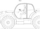
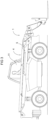
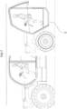
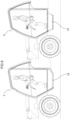
- the invention relates to a load handling machine 1 of the type shown in Figure 2
- This machine 1 comprises a chassis 2 movable on the ground, produced here in the form of a rolling chassis 2 equipped with four wheels and a powertrain.
- This machine 1 comprises a driver's cabin 3 carried by the chassis 2 inside which a driver can sit.
- This machine 1 also comprises a load handling system 4 comprising at least one lifting arm 5.
- This lifting arm 5 which extends in the front/rear direction of the machine, is a pivoting arm, mounted to pivot about a so-called horizontal axis. parallel to the ground support plane of the machine when the machine is positioned on a horizontal flat surface, for the passage of the lifting arm from a low position to a high position and vice versa.
- the pivot axis of the arm extends transversely to the front/rear direction of the machine.
- This lifting arm 5 may be a telescopic arm as in the example shown.
- This lifting arm 5 may be equipped, at its end, with a load handling accessory, such as a fork, a cradle or other.
- the pilot cabin 3 and the lifting arm 5 are arranged side by side along a line transverse to the front/rear direction of the machine, which makes it possible to have a very long lifting arm 5.
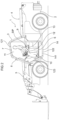
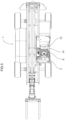
- the cabin 3 comprises a floor 6, a ceiling 7, a front face 8, an opposite rear face 9 and two opposite side faces shown at 10 and 11 in the figures with the side face 10 provided with an opening 12 for access to the cabin 3 and the side face 11 adjoined by the lifting arm 5 at least in the low position of said arm 5.
- the opening 12 for access to the cabin can be closed by a door.
- the pivot axis connecting the lifting arm 5 to the chassis 2 is arranged at the rear of the machine 1 so that in the high position of the lifting arm 5, the latter partially extends to a level higher than that of the ceiling of the cabin 3. In the low position, this lifting arm 5 extends at least partially along the lateral face 11 of the cabin 3.
- This lateral arrangement of the lifting arm 5 relative to the cabin 3 requires the driver to be positioned in the cabin 3 such that the driver's eyes are arranged at a level higher than that of the lifting arm 5 in the low position of the lifting arm 5, as illustrated in Figure 2 , to allow the driver of the machine to have so-called high peripheral vision.
- This cabin 3 is equipped with a seat 13 and has at least one seat reference point called SIP established and defined according to the international standard ISO 5353:1995.
- This international standard corresponds to the European standard EN ISO 5353:1998 which also has the status of a French standard NF EN ISO 5353 of November 1998.
- This international standard prescribes a method and the device to be used for determining the seat reference point SIP for any type of seat.
- the SIP seat reference point as established and defined in the international standard, may be considered, for cab design, as the intersection between the vertical plane passing through the seat centerline and the theoretical axis of articulation between the driver's trunk and thighs.
- the SIP seat reference point is fixed relative to the machine and does not move with the seat depending on the adjustments and/or the oscillation range of the seat. This SIP seat reference point is specified by the machine manufacturer.
- the cabin 3 has a minimum interior height H taken between the floor 6 and the ceiling 7 at the level of the reference point of the SIP seat, i.e. vertically or in line with said reference point of the SIP seat, greater than 1705 mm. This height is much greater than that of the cabins of the state of the art which generally does not exceed 1550 mm.
- cab floor when the machine is positioned on a flat horizontal surface, means the horizontal surface of the cab floor located directly above, i.e. vertically above, the seat, and on which the driver's feet rest to get up and/or sit on the seat.
- the machine 1 has at least one step 14 for access to the floor 6 of the cabin 3.
- the machine 1 has a single step 14 for access to the floor 4 of the cabin 3.
- This access step 14 is arranged here inside the cabin 3.
- this access step 14 can be arranged outside the cabin 3 of the cabin as shown in figure 8 .
- the machine 1 may be without a step providing access to the cabin floor.
- This arrangement offers greater safety than access steps and a floor arranged in the manner of a ladder one above the other as is the case in the prior art.
Landscapes
- Engineering & Computer Science (AREA)
- Structural Engineering (AREA)
- Transportation (AREA)
- Mechanical Engineering (AREA)
- Life Sciences & Earth Sciences (AREA)
- Geology (AREA)
- Civil Engineering (AREA)
- Chemical & Material Sciences (AREA)
- Combustion & Propulsion (AREA)
- Mining & Mineral Resources (AREA)
- General Engineering & Computer Science (AREA)
- Body Structure For Vehicles (AREA)
- Forklifts And Lifting Vehicles (AREA)
Claims (8)
- Lastbewegungsmaschine (1), umfassend ein Fahrgestell (2), das auf dem Boden bewegbar ist, eine Steuerkabine (3) und ein System (4) zum Bewegen von Lasten, die von dem Fahrgestell (2) getragen werden, das System (4) zum Bewegen umfassend mindestens einen Hebearm (5), der bewegbar zwischen einer oberen und einer unteren Position montiert ist, und die Kabine (3) umfassend einen Boden (6), eine Decke (7), eine Vorderseite (8), eine gegenüberliegende Rückseite (9) und zwei seitliche Seiten (10, 11) wobei eine (10) der seitlichen Seiten (10, 11) mit einer Öffnung (12) für den Zugang zu der Kabine (3), die durch eine Tür geschlossen werden kann, versehen ist, und die andere seitliche Seite (11) zumindest in der unteren Position des Arms (5) an den Hebearm (5) angrenzt, wobei die Kabine (3) mit einem Sitz (13) ausgestattet ist und mindestens einen Sitzreferenzpunkt, genannt SIP, aufweist, der gemäß der internationalen Norm ISO 5353:1995 festgelegt und definiert ist, dadurch gekennzeichnet, dass die Kabine (3) eine minimale innere Höhe (H), genommen zwischen dem Boden (6) und der Decke (7), an dem Sitzreferenzpunkt SIP, von mehr als 1705 mm und in dem positionierten Zustand des Fahrzeugs (1) auf einer horizontalen ebenen Bodenfläche einen Abstand (D1) zwischen dem Boden (6) und dem Boden von weniger als 800 mm aufweist, und dass der Abstand (D2) zwischen dem oder jedem Sitzreferenzpunkt SIP und dem Boden (6) der Kabine (3) mindestens 650 mm ist.
- Lastbewegungsmaschine (1) nach Anspruch 1, dadurch gekennzeichnet, dass der Abstand (D2) zwischen dem oder jedem Sitzreferenzpunkt SIP und dem Boden (6) der Kabine (3) weniger als 1045 mm ist.
- Lastbewegungsmaschine (1) nach einem der Ansprüche 1 oder 2, dadurch gekennzeichnet, dass die Maschine (1) mindestens eine Stufe (14) für den Zugang zum Boden (6) der Kabine (3) aufweist.
- Lastbewegungsmaschine (1) nach Anspruch 3, dadurch gekennzeichnet, dass die Lastbewegungsmaschine (1) eine einzige Stufe (14) für den Zugang zum Boden (6) der Kabine (3) aufweist.
- Lastbewegungsmaschine (1) nach einem der Ansprüche 3 oder 4, dadurch gekennzeichnet, dass die oder mindestens eine der Stufen (14) für den Zugang zum Boden (6) der Kabine (3) innerhalb der Kabine (3) angeordnet ist.
- Lastbewegungsmaschine (1) nach einem der Ansprüche 3 bis 5, dadurch gekennzeichnet, dass die Öffnung (12) für den Zugang zu der Kabine (3) durch einen oberen Rand (121), einen unteren Rand (122) und seitliche Ränder (123) begrenzt ist, und dass die oder mindestens eine der Stufen (14) für den Zugang zum Boden (6) der Kabine (3) einen Absatz (141) aufweist, der der horizontalen ebenen Fläche der Stufe entspricht, auf die der Fuß aufgesetzt wird, und der auf Höhe des unteren Rands (122) der Öffnung (12) für den Zugang zu der Kabine (3) angeordnet ist.
- Lastbewegungsmaschine (1) nach Anspruch 6, dadurch gekennzeichnet, dass in dem positionierten Zustand der Maschine (1) auf einer horizontalen ebenen Fläche der untere Rand (122) der Öffnung (12) für den Zugang um einen Abstand (D3) von mindestens 150 mm und vorzugsweise höchstens 800 mm von dem Boden beabstandet ist.
- Lastbewegungsmaschine (1) nach einem der Ansprüche 3 bis 7, dadurch gekennzeichnet, dass der Boden (6) und die Stufe (14) für den Zugang zum Boden (6), die unmittelbar vor dem Boden (6) angeordnet ist, bezogen auf die Richtung der Einführung in die Kabine (3) durch die Öffnung (12) für den Zugang, zueinander versetzt sind, um eine Treppe zu bilden.
Applications Claiming Priority (2)
| Application Number | Priority Date | Filing Date | Title |
|---|---|---|---|
| FR2101826A FR3120027B1 (fr) | 2021-02-25 | 2021-02-25 | Engin de manutention de charge |
| PCT/FR2022/050252 WO2022180317A1 (fr) | 2021-02-25 | 2022-02-11 | Engin de manutention de charge |
Publications (3)
| Publication Number | Publication Date |
|---|---|
| EP4298050A1 EP4298050A1 (de) | 2024-01-03 |
| EP4298050B1 true EP4298050B1 (de) | 2025-04-02 |
| EP4298050C0 EP4298050C0 (de) | 2025-04-02 |
Family
ID=75850298
Family Applications (1)
| Application Number | Title | Priority Date | Filing Date |
|---|---|---|---|
| EP22708979.4A Active EP4298050B1 (de) | 2021-02-25 | 2022-02-11 | Lasthandhabungsfahrzeug |
Country Status (4)
| Country | Link |
|---|---|
| US (1) | US20240227951A9 (de) |
| EP (1) | EP4298050B1 (de) |
| FR (1) | FR3120027B1 (de) |
| WO (1) | WO2022180317A1 (de) |
Families Citing this family (1)
| Publication number | Priority date | Publication date | Assignee | Title |
|---|---|---|---|---|
| GB2623565B8 (en) * | 2022-10-20 | 2025-07-23 | Bamford Excavators Ltd | A material handling machine |
Family Cites Families (7)
| Publication number | Priority date | Publication date | Assignee | Title |
|---|---|---|---|---|
| GB1427076A (en) * | 1972-07-06 | 1976-03-03 | Rudolf Hausherr Soehne Kg Masc | Machine for driving a mine gallery or the like |
| DE9302376U1 (de) * | 1993-02-18 | 1993-06-24 | EC Engineering + Consulting Spezialmaschinen GmbH, 7900 Ulm | Kranfahrzeug |
| JP5054802B2 (ja) * | 2010-05-24 | 2012-10-24 | 日立建機株式会社 | 建設機械 |
| DE102010053752A1 (de) * | 2010-12-08 | 2012-06-14 | Grammer Aktiengesellschaft | Fahrzeugschwingungsvorrichtung für Fahrzeugsitze oder Fahrzeugkabinen |
| GB2528091B (en) * | 2014-07-09 | 2020-11-25 | Bamford Excavators Ltd | Operator compartment structure |
| ITUB20159622A1 (it) * | 2015-12-28 | 2017-06-28 | Manitou Italia Srl | Macchina operatrice semovente |
| US20160244945A1 (en) * | 2016-04-29 | 2016-08-25 | Caterpillar Inc. | Tread plate assembly for machine |
-
2021
- 2021-02-25 FR FR2101826A patent/FR3120027B1/fr active Active
-
2022
- 2022-02-11 US US18/546,506 patent/US20240227951A9/en active Pending
- 2022-02-11 EP EP22708979.4A patent/EP4298050B1/de active Active
- 2022-02-11 WO PCT/FR2022/050252 patent/WO2022180317A1/fr not_active Ceased
Also Published As
| Publication number | Publication date |
|---|---|
| US20240132163A1 (en) | 2024-04-25 |
| EP4298050C0 (de) | 2025-04-02 |
| FR3120027A1 (fr) | 2022-08-26 |
| WO2022180317A1 (fr) | 2022-09-01 |
| EP4298050A1 (de) | 2024-01-03 |
| FR3120027B1 (fr) | 2023-02-10 |
| US20240227951A9 (en) | 2024-07-11 |
Similar Documents
| Publication | Publication Date | Title |
|---|---|---|
| CA2572722A1 (fr) | Vehicule motorise a inclinaison limitee | |
| FR3018052A1 (fr) | Machine de travail, notamment camion a benne | |
| EP4298050B1 (de) | Lasthandhabungsfahrzeug | |
| FR3066223A1 (fr) | Systeme de fixation de roulette escamotable de marchepied, et marchepied comprenant au moins un systeme de fixation de roulette escamotable | |
| AU2012326296B2 (en) | Maximizing scissor lift breakover angle with fixed pothole protection | |
| EP1137568B1 (de) | Einspuhrfahrzeug mit von der geschwindigkeit abhängigen, ausschwenkbaren stabilisierungsrädern | |
| EP3064418B1 (de) | Förderwagen | |
| FR2962699A1 (fr) | Banquette pour vehicule utilitaire a espace de chargement utile allonge | |
| US8668427B1 (en) | Bridge for a tailgate of a pickup truck | |
| EP3463988B1 (de) | Befestigungsvorrichtung und trittbrett mit solch einer vorrichtung | |
| EP1077196B1 (de) | Vorrichtung zum Korrigieren der Schiefstellung für ein zweiachsiges Fahrzeug | |
| FR3071472A1 (fr) | Vehicule agricole avec correction de glissement par les roues arriere | |
| FR3060514A1 (fr) | Dispositif de rangement d'une roue dans un coffre d'un vehicule automobile et vehicule automobile comportant un tel dispositif | |
| EP3649015B1 (de) | Mit ladungsschutz ausgestattetes kraftfahrzeug mit sitzrückenlehnenhaltevorrichtung | |
| FR3139129A1 (fr) | Engin de manutention de charge | |
| EP2910513A1 (de) | Hebevorrichtung mit einer Regulierung der Höhenlage | |
| FR3091840A1 (fr) | Ensemble d’affichage à parties combinables et élément de garnissage associé | |
| EP4049890B1 (de) | Sitz mit armlehne(n) und entsprechendes transportfahrzeug | |
| EP4072927B1 (de) | Vorrichtung zur befestigung eines querträgers einer fahrerkabine eines kraftfahrzeugs | |
| FR2809586A1 (fr) | Engin automoteur notamment pour operations de traitement et d'entretien de cultures | |
| EP4008300A1 (de) | Zugangsvorrichtung zu einer fahrerkabine eines fahrzeugs und fahrzeug mit einer solchen zugangsvorrichtung | |
| FR3113482A1 (fr) | Véhicule comprenant un dispositif de retenue de la roue de secours | |
| FR3146800A1 (fr) | Système de Motorisation Auxiliaire pour Fauteuil Roulant Manuel | |
| EP1418280A1 (de) | Fahrerkabine für Rad- oder Raupenfahrzeuge | |
| FR3145527A1 (fr) | Système de levage et de stabilisation d’un vehicule |
Legal Events
| Date | Code | Title | Description |
|---|---|---|---|
| STAA | Information on the status of an ep patent application or granted ep patent |
Free format text: STATUS: UNKNOWN |
|
| STAA | Information on the status of an ep patent application or granted ep patent |
Free format text: STATUS: THE INTERNATIONAL PUBLICATION HAS BEEN MADE |
|
| PUAI | Public reference made under article 153(3) epc to a published international application that has entered the european phase |
Free format text: ORIGINAL CODE: 0009012 |
|
| STAA | Information on the status of an ep patent application or granted ep patent |
Free format text: STATUS: REQUEST FOR EXAMINATION WAS MADE |
|
| 17P | Request for examination filed |
Effective date: 20230911 |
|
| AK | Designated contracting states |
Kind code of ref document: A1 Designated state(s): AL AT BE BG CH CY CZ DE DK EE ES FI FR GB GR HR HU IE IS IT LI LT LU LV MC MK MT NL NO PL PT RO RS SE SI SK SM TR |
|
| DAV | Request for validation of the european patent (deleted) | ||
| DAX | Request for extension of the european patent (deleted) | ||
| GRAP | Despatch of communication of intention to grant a patent |
Free format text: ORIGINAL CODE: EPIDOSNIGR1 |
|
| STAA | Information on the status of an ep patent application or granted ep patent |
Free format text: STATUS: GRANT OF PATENT IS INTENDED |
|
| INTG | Intention to grant announced |
Effective date: 20241009 |
|
| GRAS | Grant fee paid |
Free format text: ORIGINAL CODE: EPIDOSNIGR3 |
|
| GRAA | (expected) grant |
Free format text: ORIGINAL CODE: 0009210 |
|
| STAA | Information on the status of an ep patent application or granted ep patent |
Free format text: STATUS: THE PATENT HAS BEEN GRANTED |
|
| AK | Designated contracting states |
Kind code of ref document: B1 Designated state(s): AL AT BE BG CH CY CZ DE DK EE ES FI FR GB GR HR HU IE IS IT LI LT LU LV MC MK MT NL NO PL PT RO RS SE SI SK SM TR |
|
| REG | Reference to a national code |
Ref country code: GB Ref legal event code: FG4D Free format text: NOT ENGLISH |
|
| REG | Reference to a national code |
Ref country code: CH Ref legal event code: EP |
|
| REG | Reference to a national code |
Ref country code: IE Ref legal event code: FG4D Free format text: LANGUAGE OF EP DOCUMENT: FRENCH |
|
| REG | Reference to a national code |
Ref country code: DE Ref legal event code: R096 Ref document number: 602022012578 Country of ref document: DE |
|
| U01 | Request for unitary effect filed |
Effective date: 20250428 |
|
| U07 | Unitary effect registered |
Designated state(s): AT BE BG DE DK EE FI FR IT LT LU LV MT NL PT RO SE SI Effective date: 20250506 |
|
| PG25 | Lapsed in a contracting state [announced via postgrant information from national office to epo] |
Ref country code: ES Free format text: LAPSE BECAUSE OF FAILURE TO SUBMIT A TRANSLATION OF THE DESCRIPTION OR TO PAY THE FEE WITHIN THE PRESCRIBED TIME-LIMIT Effective date: 20250402 |
|
| PG25 | Lapsed in a contracting state [announced via postgrant information from national office to epo] |
Ref country code: GR Free format text: LAPSE BECAUSE OF FAILURE TO SUBMIT A TRANSLATION OF THE DESCRIPTION OR TO PAY THE FEE WITHIN THE PRESCRIBED TIME-LIMIT Effective date: 20250703 Ref country code: NO Free format text: LAPSE BECAUSE OF FAILURE TO SUBMIT A TRANSLATION OF THE DESCRIPTION OR TO PAY THE FEE WITHIN THE PRESCRIBED TIME-LIMIT Effective date: 20250702 |
|
| PG25 | Lapsed in a contracting state [announced via postgrant information from national office to epo] |
Ref country code: PL Free format text: LAPSE BECAUSE OF FAILURE TO SUBMIT A TRANSLATION OF THE DESCRIPTION OR TO PAY THE FEE WITHIN THE PRESCRIBED TIME-LIMIT Effective date: 20250402 |
|
| PG25 | Lapsed in a contracting state [announced via postgrant information from national office to epo] |
Ref country code: HR Free format text: LAPSE BECAUSE OF FAILURE TO SUBMIT A TRANSLATION OF THE DESCRIPTION OR TO PAY THE FEE WITHIN THE PRESCRIBED TIME-LIMIT Effective date: 20250402 |
|
| PG25 | Lapsed in a contracting state [announced via postgrant information from national office to epo] |
Ref country code: RS Free format text: LAPSE BECAUSE OF FAILURE TO SUBMIT A TRANSLATION OF THE DESCRIPTION OR TO PAY THE FEE WITHIN THE PRESCRIBED TIME-LIMIT Effective date: 20250702 |
|
| PG25 | Lapsed in a contracting state [announced via postgrant information from national office to epo] |
Ref country code: IS Free format text: LAPSE BECAUSE OF FAILURE TO SUBMIT A TRANSLATION OF THE DESCRIPTION OR TO PAY THE FEE WITHIN THE PRESCRIBED TIME-LIMIT Effective date: 20250802 |
|
| PG25 | Lapsed in a contracting state [announced via postgrant information from national office to epo] |
Ref country code: SM Free format text: LAPSE BECAUSE OF FAILURE TO SUBMIT A TRANSLATION OF THE DESCRIPTION OR TO PAY THE FEE WITHIN THE PRESCRIBED TIME-LIMIT Effective date: 20250402 |
|
| PG25 | Lapsed in a contracting state [announced via postgrant information from national office to epo] |
Ref country code: CZ Free format text: LAPSE BECAUSE OF FAILURE TO SUBMIT A TRANSLATION OF THE DESCRIPTION OR TO PAY THE FEE WITHIN THE PRESCRIBED TIME-LIMIT Effective date: 20250402 |
|
| PG25 | Lapsed in a contracting state [announced via postgrant information from national office to epo] |
Ref country code: SK Free format text: LAPSE BECAUSE OF FAILURE TO SUBMIT A TRANSLATION OF THE DESCRIPTION OR TO PAY THE FEE WITHIN THE PRESCRIBED TIME-LIMIT Effective date: 20250402 |
|
| PLBE | No opposition filed within time limit |
Free format text: ORIGINAL CODE: 0009261 |
|
| STAA | Information on the status of an ep patent application or granted ep patent |
Free format text: STATUS: NO OPPOSITION FILED WITHIN TIME LIMIT |
|
| REG | Reference to a national code |
Ref country code: CH Ref legal event code: L10 Free format text: ST27 STATUS EVENT CODE: U-0-0-L10-L00 (AS PROVIDED BY THE NATIONAL OFFICE) Effective date: 20260211 |
|
| 26N | No opposition filed |
Effective date: 20260105 |
|
| U20 | Renewal fee for the european patent with unitary effect paid |
Year of fee payment: 5 Effective date: 20260225 |
|
| PGFP | Annual fee paid to national office [announced via postgrant information from national office to epo] |
Ref country code: GB Payment date: 20260220 Year of fee payment: 5 |