EP4298016B1 - Luftfahrzeug mit flügel-klappmechanismus - Google Patents
Luftfahrzeug mit flügel-klappmechanismus Download PDFInfo
- Publication number
- EP4298016B1 EP4298016B1 EP22707146.1A EP22707146A EP4298016B1 EP 4298016 B1 EP4298016 B1 EP 4298016B1 EP 22707146 A EP22707146 A EP 22707146A EP 4298016 B1 EP4298016 B1 EP 4298016B1
- Authority
- EP
- European Patent Office
- Prior art keywords
- aircraft
- wings
- flight
- state
- carrier
- Prior art date
- Legal status (The legal status is an assumption and is not a legal conclusion. Google has not performed a legal analysis and makes no representation as to the accuracy of the status listed.)
- Active
Links
Images
Classifications
-
- B—PERFORMING OPERATIONS; TRANSPORTING
- B64—AIRCRAFT; AVIATION; COSMONAUTICS
- B64D—EQUIPMENT FOR FITTING IN OR TO AIRCRAFT; FLIGHT SUITS; PARACHUTES; ARRANGEMENT OR MOUNTING OF POWER PLANTS OR PROPULSION TRANSMISSIONS IN AIRCRAFT
- B64D3/00—Aircraft adaptations to facilitate towing or being towed
-
- B—PERFORMING OPERATIONS; TRANSPORTING
- B64—AIRCRAFT; AVIATION; COSMONAUTICS
- B64D—EQUIPMENT FOR FITTING IN OR TO AIRCRAFT; FLIGHT SUITS; PARACHUTES; ARRANGEMENT OR MOUNTING OF POWER PLANTS OR PROPULSION TRANSMISSIONS IN AIRCRAFT
- B64D5/00—Aircraft transported by aircraft, e.g. for release or reberthing during flight
-
- B—PERFORMING OPERATIONS; TRANSPORTING
- B64—AIRCRAFT; AVIATION; COSMONAUTICS
- B64U—UNMANNED AERIAL VEHICLES [UAV]; EQUIPMENT THEREFOR
- B64U10/00—Type of UAV
- B64U10/25—Fixed-wing aircraft
-
- B—PERFORMING OPERATIONS; TRANSPORTING
- B64—AIRCRAFT; AVIATION; COSMONAUTICS
- B64U—UNMANNED AERIAL VEHICLES [UAV]; EQUIPMENT THEREFOR
- B64U30/00—Means for producing lift; Empennages; Arrangements thereof
- B64U30/10—Wings
- B64U30/12—Variable or detachable wings, e.g. wings with adjustable sweep
-
- B—PERFORMING OPERATIONS; TRANSPORTING
- B64—AIRCRAFT; AVIATION; COSMONAUTICS
- B64U—UNMANNED AERIAL VEHICLES [UAV]; EQUIPMENT THEREFOR
- B64U70/00—Launching, take-off or landing arrangements
- B64U70/20—Launching, take-off or landing arrangements for releasing or capturing UAVs in flight by another aircraft
-
- B—PERFORMING OPERATIONS; TRANSPORTING
- B64—AIRCRAFT; AVIATION; COSMONAUTICS
- B64U—UNMANNED AERIAL VEHICLES [UAV]; EQUIPMENT THEREFOR
- B64U80/00—Transport or storage specially adapted for UAVs
- B64U80/80—Transport or storage specially adapted for UAVs by vehicles
- B64U80/82—Airborne vehicles
-
- B—PERFORMING OPERATIONS; TRANSPORTING
- B64—AIRCRAFT; AVIATION; COSMONAUTICS
- B64U—UNMANNED AERIAL VEHICLES [UAV]; EQUIPMENT THEREFOR
- B64U2101/00—UAVs specially adapted for particular uses or applications
- B64U2101/15—UAVs specially adapted for particular uses or applications for conventional or electronic warfare
Definitions
- the invention relates to an aircraft, in particular a missile.
- Aircraft or missiles (MV), in particular cruise missiles, are known from practice, e.g. in the form of the "Taurus KEPD-350" with a rectangular fuselage and two fold-out wings arranged on the upper side of the fuselage or in the form of the "BGM-109 Tomahawk".
- folding or pivoting wings are used, which are completely or partially recessed into the fuselage in the packed configuration or a packed state and are pivoted out in flight or a flight state.
- US 2017/260973 A1 discloses a pivoting arrangement for wings of an aircraft.
- CN 109 367 760 A discloses a wing arrangement for an aircraft.
- WO 2018/044182 A2 discloses a principle for moving wings of an aircraft.
- US 2021/0033371A1 reveals an aircraft with foldable wings mounted on a fuselage.
- the object of the invention is to propose an improved aircraft.
- the aircraft has a longitudinal axis which corresponds to the direction of flight during normal operation, i.e. when the aircraft is flying.
- the aircraft contains two wings. Each of the wings extends along a respective wing axis.
- the aircraft contains a folding bearing which is arranged on the longitudinal axis. In particular, the folding bearing is penetrated by the longitudinal axis, in particular it is designed symmetrically to the longitudinal axis. Both wings have two longitudinal ends along their wing axes. One of the longitudinal ends is a bearing end.
- the wings are hingedly mounted on the folding bearing with their respective bearing ends.
- the folding bearing thus provides the corresponding folding functionality. In a folded state, also known as the packed state, the wings are aligned with their wing axes along the longitudinal axis.
- the wing axes run parallel to the longitudinal axis or are only rotated by a few degrees relative to it, in particular less than 3° or less than 5° or less than 10°.
- an unfolded state also known as the flight state
- the wing axes are aligned at an angle or transversely to the longitudinal axis.
- the folding bearing is arranged at the bow of the aircraft.
- “Oblique” means an angle of greater than zero degrees and less than 90°, in particular at least 10° or at least 20° or at least 30° between the wing axis and the longitudinal axis.
- Transverse means angles in the range of 90°, in particular exactly 90° or 88° to 92° or 85° to 95° or 80° to 100°.
- the arrangement "at the bow” is to be understood as meaning that the folding bearing forms the bow or the nose of the aircraft or, for all possible folding states, a distance from the nose of the aircraft to the beginning of the folding bearing is no more than 20%, in particular no more than 15%, in particular no more than 10%, in particular, does not exceed 5% of the longitudinal dimension of the entire aircraft.
- the folding bearing is in particular a pivot bearing that has a common pivot axis for both wings or two separate pivot axes for each wing.
- the pivot axes run in particular parallel to one another and in particular at least one of them runs parallel to the yaw axis of the aircraft.
- the aircraft is optionally designed passively as a glider or with a drive device.
- the drive device is arranged in particular on one or both wings or on another structural part of the aircraft.
- the folding location i.e. the pivot, swivel or articulation point for the folding, swivel, rotational movement, etc. of the wings, is also at the bow.
- the wings can therefore extend from this folding bearing over the entire length and thus have the entire length along their wing axis. Because of the comparatively large wing length, the greatest possible wing extension or wingspan of the aircraft can be achieved in the flight state, even if the folding bearing is a pivot bearing and the wings themselves are rigid, i.e. have no further folding joints or similar. If the wings protrude transversely in the flight state, this is then about twice the total length of the wingspan of the aircraft. This means that particularly good lift properties can be achieved for the aircraft, which increases its range.
- the wings are folded in the packed state in such a way that, for a given geometry of the aircraft and a given folding kinetics (movement path of the folding mechanism, rotation mechanism, etc.), the smallest possible transverse dimension for the aircraft is achieved.
- a folding kinetics movement path of the folding mechanism, rotation mechanism, etc.
- one is selected that enables the smallest possible packing size of the aircraft in terms of its transverse dimension (two dimensions transverse to the longitudinal axis).
- the corresponding considerations are particularly taken into account during a design phase. of the aircraft.
- a corresponding folding or rotating position can then be selected in the specific aircraft design as the end position for a folding, rotating or other movement.
- the other folding, rotating or other positions that are theoretically possible in the design step then no longer have to be attainable in the specific aircraft.
- This storage device or storage space can be, for example, an internal weapons bay or a cargo hold of a carrier.
- the carrier also called a "carrier vehicle”
- an aircraft that is as large as possible - especially in flight mode - or one with the largest possible wingspan can be stowed, since in its packed state, due to the smallest possible transverse dimensions, it requires less space than in flight mode.
- the folding bearing is a connecting piece for the wings through which the longitudinal axis passes.
- the wings are thus mounted or hingedly attached to one another via the folding bearing.
- both wings are mounted separately on the folding bearing so that they can be folded, in particular via two pivot bearings, so that the folding bearing represents a double pivot bearing. This results in a particularly simple embodiment of the aircraft.
- the aircraft contains a drive device arranged on the connecting piece.
- the drive device is thus arranged centrally in the aircraft and not on the wings. This means that it does not have to be folded along, particularly when the wings are folded.
- the drive device can be any type of aviation drive, in particular an aircraft engine, e.g. with a propeller, or a jet engine.
- the aircraft is designed to carry payloads within the wings or on the wings, in particular only within.
- the arrangement of the folding bearing on the bow side makes comparatively large wings possible for a given packing size of the aircraft in the packed state.
- the wings are therefore intended for payload and other structural parts of the aircraft, e.g. a fuselage, can be made smaller or eliminated. This reduces the aircraft's air resistance and thus increases its range.
- the payload is in particular a sensor system and/or a warhead and/or a control device and/or a communication device and/or a fuel for the possible propulsion device.
- a particularly versatile aircraft can be created by means of appropriate payloads.
- a radar device is arranged as a payload in at least one of the wings.
- the radar device is in particular a SAR device (synthetic aperture radar), which is in particular divided between both wings. In particular, this has a scanning direction in the direction of flight and/or towards the ground.
- the aircraft is thus equipped with a particularly powerful radar architecture.
- the aircraft is designed without a fuselage or, in other words, without a fuselage.
- the aircraft therefore essentially only consists of the wings and the folding bearing, possibly as a connecting piece, and possibly also a drive device, none of which count as a "fuselage" in the present sense.
- the folding bearing can preferably also serve as a connecting piece for the wings; alternatively, a separate connecting piece can be provided.
- the "fuselage” is understood to be a conventional hollow body for accommodating structural parts (e.g. wing box) and internals (e.g. fuel tank, warhead, communication, ).
- This embodiment, in which the aircraft with the two wings and the folding bearing is designed without a fuselage and can optionally also include a drive device, is particularly suitable for combination with the accommodation of payload in the wings.
- the longitudinal extent of the aircraft can be minimized by folding out the wings.
- the aircraft consists of the wings and the folding bearing - apart from any separate connecting piece and apart from an optional drive device on the folding bearing or connecting piece - the longitudinal extent of the aircraft can be minimized by folding out the wings.
- the longitudinal extent of the aircraft can be reduced during the transition from the packed state to the flying state.
- the minimization of the longitudinal extent of the aircraft during the transition from the packed state to the flight state is ensured by the total length of the aircraft in the packed state extending from the bow to the longitudinal ends of the wings or, in other words, the length of the wings in the packed state/folded state is greater than the longitudinal extent of the connecting piece and/or the drive device or the rear area of the aircraft is formed by the longitudinal ends of the wings.
- the length of the wings along their wing axis is particularly preferably at least 1.5 x, in particular at least 2 x as long as the length of the connecting piece and/or the length of the drive device in relation to the longitudinal axis of the aircraft.
- the wings have a sweep in the flight state.
- the sweep consists in particular in that the wing axes have an angle of between 35° and 75°, in particular between 40° and 65°, in particular between 45° and 60°, with the longitudinal axis. Due to a corresponding sweep, the cross-sectional profile of the wings is extended in the direction of flight compared to a transverse arrangement of the wings, so that - in particular for a large-scale accommodation of payload in the wing - a larger installation space height in the wing is possible with increasing sweep while maintaining the same flight characteristics, namely a constant profile cross-section in the direction of flight.
- the wings can also run transversely to the longitudinal axis in flight, so that the wing axes coincide and form an angle of 90° with the longitudinal axis. (see the possible angle ranges above). This allows the maximum wing aspect ratio or span of the aircraft to be achieved for a given wing length.
- the aircraft contains an activation device that can be operated or driven from outside the aircraft.
- the activation device serves as a folding device. When it is activated or operated, it is designed to move the wings from the packed state to the flight state, i.e. to fold them out and thereby activate the aircraft's final readiness for flight.
- the activation device is therefore designed to be driveless or passive with respect to the aircraft.
- energy is supplied from outside the aircraft, e.g. from a carrier deploying the aircraft. This means that no drive or similar device needs to be provided in the aircraft to move the wings into the flight state, which makes the aircraft simple and light and thus increases its range.
- the activation device contains a traction device, in particular a traction cable, which leads away from the aircraft in the direction of flight at least when the activation device is in operation.
- the traction device is designed to be detachable from the rest of the activation device. "In the direction of flight” is to be understood as “directed forwards", so that at least one directional component points in the direction of flight, i.e. the traction device at least does not lead away from the aircraft transversely. Such a direction of the traction device allows the aircraft to be towed in the air, e.g. towed by a carrier.
- the activation device is designed to transfer the tension to the folding mechanism and/or the wings when there is tension (i.e.
- the aircraft can be ejected from a carrier in the packed state, e.g. from the rear, in particular from a weapon bay or storage space located in the rear area of the aircraft, in order to be able to be towed by means of a traction device from this to be towed through the air.
- the traction device remains connected to the carrier.
- the aircraft experiences air resistance relative to the carrier, which creates tension on the traction device.
- the tension on the traction device is then introduced into the rest of the activation device within the aircraft, e.g. a folding mechanism of the folding bearing and/or the wings, in order to move the wings from the packed state to the flight state.
- the traction device can be released from the aircraft and thus from the rest of the activation device and the aircraft can begin its own flight.
- the aircraft is an autonomous aircraft, e.g. a "remote carrier", of a ("future") networked air combat system, e.g. a "FCAS” (Future Combat Air System).
- the aircraft is in particular a missile, a cruise missile, a drone, etc. Thanks to the solution proposed here, particularly powerful autonomous aircraft can be created as remote carriers, which have comparatively good flight characteristics and ranges despite their small packing dimensions. This creates an overall particularly powerful networked air combat system (FCAS).
- FCAS networked air combat system
- the aircraft is designed to be stowable or attachable in a receiving device, in particular a weapon bay and/or an external station and/or a cargo hold and/or a storage space of a carrier, when packed.
- a receiving device in particular a weapon bay and/or an external station and/or a cargo hold and/or a storage space of a carrier, when packed.
- known geometric and other requirements for the aircraft are met, which result from the receiving device, e.g. the weapon bay and/or external station and/or cargo hold and/or storage space, for which the aircraft is intended.
- "Intended" means that the aircraft is structurally matched to a specific or a specific type of receiving device such as a weapon bay, external station, etc. and is intended for use there; e.g. it is designed for the geometric requirements determined thereby, etc. In particular, this makes it possible to create carriers that have corresponding weapon bays, etc. and can be equipped with the aircraft proposed here.
- the object of the invention is also achieved by a flight system according to claim 9 with an aircraft according to the invention.
- the flight system further comprises a carrier (in particular a land, air or sea vehicle) with a receiving device, in particular a weapon bay and/or an external station and/or a cargo hold and/or stowage space in or on which the aircraft is or can be stowed in the packed state.
- the aircraft can also be set down from the receiving device by the carrier.
- the object of the invention is also achieved by a method according to claim 10 for deploying an aircraft having the features of claim 7 from a carrier, here a carrier aircraft.
- the method assumes that the aircraft is stowed in or on the carrier in the packed state, e.g. in the above-mentioned receiving device etc. and that the carrier aircraft is in flight and moving in a flight direction.
- the aircraft is first released from the carrier, with the traction device being held on the carrier, in particular being attached to it with an end facing away from the aircraft. Due to the air resistance to which the ejected or set down aircraft is now exposed while hanging on the traction device, the aircraft now goes into a towing state, i.e. is towed through the air by the carrier.
- the aircraft is slowed down by its air resistance, which is why a pulling force is generated on the traction device.
- the wings of the aircraft towed by the traction device are then unfolded from the packed state into the flight state by the pull on the traction device caused by the aircraft's air resistance, as explained above.
- the tensile force acting on the aircraft is therefore diverted or used within the aircraft or the (remaining) activation device or a folding device to generate a force and/or a torque that moves the wings from the packed state to the flying state. If necessary, an optional lock on the aircraft must be released to hold the wings in the packed state until a transition to the flying state is desired.
- the traction device is released from the aircraft or pulled in.
- the traction device is dropped from the aircraft and/or the carrier and/or pulled in from the carrier.
- the traction device could also remain on the aircraft and in particular be pulled in from it, but this would be undesirable in the form of useless ballast.
- pulling in the traction device is preferable.
- the solution proposed here is based on the following findings, observations and considerations and also has the following embodiments.
- the embodiments can also contain parts or combinations of the above-mentioned embodiments or correspond to them and/or possibly also include embodiments not previously mentioned.
- An autonomous aircraft is to be developed for a (networked) air combat system, in particular an FCAS system.
- the aim is to achieve long ranges and at the same time enable flexible transport with a carrier, in particular a sixth-generation multi-role combat aircraft belonging to the (future) air combat system or FCAS or other combat aircraft or transport aircraft.
- Previous aircraft (AFZ) or missiles (FK) are built in a classic fuselage-wing configuration, e.g. the above-mentioned "Taurus KEPD-350” or “BGM-109 Tomahawk". They either have very small rudders and fins and use the fuselage as a lifting body to a large extent. To achieve long ranges, conventional folding or scissor wings are used, which are completely or partially recessed into the fuselage in the packed configuration.
- the solution proposed here is based on the following idea: instead of accommodating the payload (sensors, warhead) and the fuel in one part of the fuselage, the wings are used as a supporting structure or as installation space. This makes it particularly advantageous to accommodate a SAR (synthetic aperture radar), for example, with the scanning direction being the direction of flight.
- SAR synthetic aperture radar
- the wings can be designed in such a way that the wing aspect ratio is maximized. Sweeping the wings allows the choice of a relatively thick wing profile, since in the aerodynamic section (in the direction of flight) the profile thickness is less than in a section perpendicular to the direction of extension of the wings (wing axis).
- the solution proposed here is also based on the following insight: To achieve a long range, it is advantageous to have the greatest possible wing aspect ratio and a low structural mass.
- a design without a fuselage allows the structural weight to be kept low and the non-aerodynamic aircraft parts to be minimized.
- the surface area is minimized, which leads to lower drag.
- the wing pivot point folding bearing/folding mechanism
- the wing pivot point can also be installed very far forward (when folded in), as the longitudinal extension is minimized when the aircraft is folded out.
- a conventional fuselage-wing configuration only about half of the aircraft/aircraft is available as wing length, as it must be ensured that the aerodynamic pressure point is still behind the center of gravity.
- the space saved by this configuration is particularly important when temporarily storing the aircraft for transport purposes in a transport aircraft (carrier) with internal weapon bays in which only limited storage space is available.
- a transport aircraft carrier
- the aircraft can be pulled behind the transport aircraft in a folded state (packed state) on a wire rope (traction device) and is then only unfolded due to the aerodynamic resistance and a corresponding mechanism (activation device).
- a "rigid" aircraft i.e. with non-folding wings, could only be efficiently stowed transversely to the direction of flight in the cargo hold of a transport aircraft, which makes it very difficult to leave the transport aircraft. Stabilizing an aircraft ejected in this way would be difficult, if not impossible.
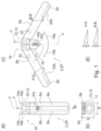
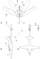
- Figure 1 shows an aircraft 2 having a longitudinal axis 4 which, during operation, i.e. during flight of the aircraft 2, corresponds to its roll axis and its flight direction F (indicated by an arrow).
- the aircraft 2 contains two wings 6a, b, which extend along a respective wing axis 8a, b.
- the aircraft 2 also contains a folding bearing 10, here in the form of a connecting piece 12 for the two wings 6a, b, through which the longitudinal axis 4 passes.
- the two wings 6a, b have a respective bearing end 14a, b in the direction of the wing axis 8a, b and are each hingedly mounted there on the folding bearing 10.
- the folding movement consists of a pure rotary movement about a respective rotation axis 16a, b, which here runs perpendicular to the longitudinal axis 4 and wing axis 8a, b and parallel to a yaw axis of the aircraft 2.
- a drive device 11 of the aircraft here a jet engine, is attached to the folding bearing 10 and here to the underside of the aircraft 2.
- Figure 1a Top view of aircraft 2 in the direction of the yaw axis
- Figure 1b Rear view in the direction of arrow Ib of the aircraft 2 in the direction of flight F
- the folding bearing 10 is arranged on the bow 18 of the aircraft 2.
- the folding bearing 10 has no distance from the bow 18, but the folding bearing 10 and the bearing ends 14a, b form the bow 18 of the aircraft 2.
- Figure 1c shows the flight state ZF of the aircraft 2.
- the wings 6a, b are unfolded in the direction of the arrows 19a,b thanks to the folding bearing 10, here rotated about the rotation axes 16a, b.
- the wing axes 8a, b now run obliquely to the longitudinal axis 4 and enclose an acute angle W with it of 60° in the embodiment.
- the aircraft 2 has control surfaces 20a, b on the wings 6a, b (not explained in detail).
- Figure 1d shows two sections through the (identical or symmetrical) wings 6a, b.
- Section AA runs transversely or perpendicularly to the wing axis 8a, b
- section BB runs parallel to the longitudinal axis 4 in flight condition ZF and thus forms the effective aerodynamic cross-section in flight of the aircraft 2.
- the sweep of the wings 6a, b makes it possible to choose a relatively thick wing profile (height H), and yet the profile thickness is smaller in the aerodynamic section BB because the effective profile is longer than the cross-section AA.
- the height H means that there is sufficient space within the wings 6a, b for the payload 22, which is only indicated here.
- the payload 22 is sensors, a warhead, a control device for operating the rudder surfaces 20a, b and the drive device 11, and a communication device for communicating with, for example, a fighter aircraft or a carrier from which the aircraft 2 was deployed.
- the aircraft 2 can be designed as an autonomous aircraft (AAV) and in particular as a component of a networked air combat system.
- AAV autonomous aircraft
- the folding bearing 10 which is approximately rectangular in plan view
- the wings 6a, b which are also approximately rectangular in plan view
- the given folding kinetics here the pure rotation about the rotation axes 16a, b
- the parallel arrangement of the wing axes 8a, b to the longitudinal axis 4 in the packed state leads to the smallest possible transverse extension Q (in every direction transverse to the longitudinal axis 4).
- any other angle of rotation of the wings 6a, b about the rotation axes 16a, b would lead to a larger transverse extension Q.
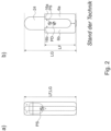
- Figure 2a shows again according to Figure 1a the aircraft 2 designed according to an embodiment of the invention in the packing state ZP.
- Figure 2b a conventional or conventional aircraft according to the state of the art, in which a corresponding folding bearing 10 is not arranged on the bow 18, but along the longitudinal axis 4 approximately in the middle of the aircraft 2.
- This shows a conventional folding wing construction.
- the wing length LF of an aircraft according to the state of the art is therefore significantly shorter than the wing length according to the aircraft 2 designed according to an embodiment of the invention, namely only about 2/3 as long.
- the total length LG and the wing length LF are the same or, expressed differently: The total length LG is determined by the wing length when the wings are folded in.
- the aircraft according to the prior art has a fuselage 24 in which the payload is accommodated.
- the wings 6a, b of the aircraft according to the prior art do not carry any payload.
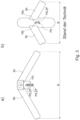
- Figure 3 shows according to Figure 2 the comparison between the aircraft 2 according to an embodiment of the invention and that according to the prior art, but now in flight mode ZF.
- Figure 3a For clarification, the movement of the center of gravity PS of aircraft 2 between packing state ZP and flight state ZF is shown again.
- Figure 3 In particular, as with the same sweep and the same overall length LG of the aircraft 2 in the packing state ZP (see Figure 2 ), a significantly greater wing aspect ratio, i.e. span or width B of the aircraft 2 according to an embodiment of the invention in flight mode ZF is achieved than in comparison to the aircraft according to the prior art.
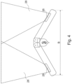
- FIG 4 explicitly shows the integration of payload 22 in the form of a radar device 26 into the two wings 6a, b.
- the radar device 26 contains two sensors in particular, here one radar sensor (SAR) in each of the wings 6a, b.
- SAR radar sensor
- a scanning area 28 of the sensors 26 is aligned in the flight direction F of the aircraft 2. An example of sensor integration is therefore shown.
- FIG. 5c shows an embodiment of the invention in which the aircraft 2 contains an activation device 30.
- the activation device 30 contains a traction device 32, here a traction cable or tow rope, which leads away from the aircraft 2 in the direction of flight or to a carrier 42 (see Figures 5a, b ) is carried out.
- the (remaining, without the traction means 32) activation device 30 is, thanks to a mechanism with a linear guide 34 and a clamping mechanism, able to redirect a pull on its traction means 32 in the flight direction F to the wings 6a, b in order to bring them into the flight state ZF.
- the traction means 32 acts on a hinge point 36 guided in the linear guide 34 and thereby drives two Articulated rods 38 which are attached between the articulation point 36 and a pivot point on the wings 6a, b.
- the Figures 5a, b show in side view and top view how the aircraft 2 first Fig. 5c from a merely indicated receiving device 40 of a carrier 42 into the open air space.
- the carrier 42 is here a transport aircraft, the receiving device 40 its cargo hold in which the aircraft 2 is transported in the packed state. After opening a loading hatch (not shown in detail), the aircraft 2 is ejected from the cargo hold against the direction of flight F, while it is still held on the carrier 42 by the traction means 32 in the form of the tow rope. Due to the air resistance or a resistance force that the aircraft 2 experiences against the direction of flight F in the towed state shown, tension is generated on the traction means 32 in the direction of flight F.
- the aircraft 2 and the carrier 42 thus form a flight system 44.
Landscapes
- Engineering & Computer Science (AREA)
- Aviation & Aerospace Engineering (AREA)
- Mechanical Engineering (AREA)
- Remote Sensing (AREA)
- Transportation (AREA)
- Tires In General (AREA)
Description
- Die Erfindung betrifft ein Luftfahrzeug, insbesondere einen Flugkörper.
- Aus der Praxis sind Luftfahrzeuge (LFZ) oder Flugkörper (FK), insbesondere Marschflugkörper, z.B. in Form des "Taurus KEPD-350" mit rechteckigem Rumpf und zwei auf der Oberseite des Rumpfes angeordneten, ausklappbaren Tragflächen oder in Form des "BGM-109 Tomahawk", bekannt.
- Um höhere Reichweiten für die Flugkörper zu erzielen, finden dabei Klapp- bzw. Schwenkflügel Verwendung, die in der Packkonfiguration bzw. einem Packzustand vollständig oder teilweise im Rumpf versenkt sind und im Flug bzw. einem Flugzustand ausgeschwenkt werden bzw. sind.
-
KR 2011 0062088 A -
US 2017/260973 A1 offenbart eine Schwenkanordnung für Flügel eines Luftfahrzeuges. -
CN 109 367 760 A offenbart eine Flügelanordnung für ein Luftfahrzeug. -
US 2017/369150 A1 offenbart ein unbemanntes Luftfahrzeug. -
WO 2018/044182 A2 offenbart ein Prinzip zum Bewegen von Flügeln eines Luftfahrzeuges. -
US 2021/0033371A1 offenbart ein Luftfahrzeug mit an einem Rumpf klappbar gelagerten Flügeln. - Aufgabe der Erfindung ist es, ein verbessertes Luftfahrzeug vorzuschlagen.
- Die Aufgabe wird gelöst durch ein Luftfahrzeug gemäß Patentanspruch 1. Bevorzugte oder vorteilhafte Ausführungsformen der Erfindung sowie anderer Erfindungskategorien ergeben sich aus den weiteren Ansprüchen, der nachfolgenden Beschreibung sowie den beigefügten Figuren.
- Das Luftfahrzeug weist eine Längsachse auf, die bei dessen regulärem Betrieb, also beim Flug des Luftfahrzeuges dessen Flugrichtung entspricht. Das Luftfahrzeug enthält zwei Flügel. Jeder der Flügel erstreckt sich entlang einer jeweiligen Flügelachse. Das Luftfahrzeug enthält ein Klapplager, das an der Längsachse angeordnet ist. Insbesondere ist das Klapplager von der Längsachse durchsetzt, insbesondere ist dieses symmetrisch zur Längsachse ausgeführt. Beide Flügel weisen entlang ihrer Flügelachsen jeweils zwei Längsenden auf. Eines der Längsenden ist jeweils ein Lagerende. Die Flügel sind mit ihren jeweiligen Lagerenden klappbar am Klapplager gelagert. Das Klapplager bewirkt also die entsprechende Klapp-Funktionalität. In einem eingeklappten Zustand, auch Packzustand, sind die Flügel mit ihren Flügelachsen längs der Längsachse ausgerichtet. Insbesondere verlaufen die Flügelachsen parallel zur Längsachse oder sind gegenüber dieser nur um wenige Grad, insbesondere kleiner 3° oder kleiner 5° oder kleiner 10° verdreht. In einem ausgeklappten Zustand, auch Flugzustand, sind die Flügelachsen schräg oder quer zur Längsachse ausgerichtet. Das Klapplager ist am Bug des Luftfahrzeuges angeordnet. "Schräg" bedeutet dabei einen Winkel von größer Null Grad und kleiner 90 °, insbesondere mindestens 10° oder mindestens 20° oder mindestens 30° zwischen Flügelachse und Längsachse. "Quer" bedeutet Winkel im Bereich von 90°, insbesondere genau 90° oder 88° bis 92° oder 85° bis 95° oder 80° bis 100°.
- Die Anordnung "am Bug" ist dabei so zu verstehen, dass das Klapplager den Bug bzw. die Bugspitze des Luftfahrzeuges bildet oder für alle möglichen Klappzustände ein Abstand von der Bugspitze des Luftfahrzeugs bis zum Beginn des Klapplagers höchstens 20%, insbesondere höchstens 15%, insbesondere höchstens 10%, insbesondere höchstens 5% der Längsausdehnung des gesamten Luftfahrzeuges beträgt.
- Das Klapplager ist insbesondere ein Schwenklager, das eine gemeinsame Schwenkachse für beide Flügel oder zwei getrennte Schwenkachsen für je einen Flügel aufweist. Die Schwenkachsen verlaufen insbesondere parallel zueinander und insbesondere wenigstens eine davon parallel zur Gierachse des Luftfahrzeuges. Das Luftfahrzeug ist optional passiv als Segelflugzeug oder mit einer Antriebsvorrichtung ausgeführt. Die Antriebsvorrichtung ist dabei insbesondere an einem oder beiden Flügeln oder an einem sonstigen Strukturteil des Luftfahrzeuges angeordnet.
- Durch die Anordnung des Klapplagers am Bug des Luftfahrzeugs kann Folgendes erreicht werden: Der Klapp-Ort, also z.B. Dreh-, Schwenk- oder Gelenkpunkt für die Klapp-, Schwenk-, Drehbewegung usw. der Flügel liegt ebenfalls am Bug. Bei einer gegebenen Gesamtlänge des Luftfahrzeuges im Packzustand können die Flügel sich daher von diesem Klapplager aus über die Gesamtlänge erstrecken und so selbst entlang ihrer Flügelachse die Gesamtlänge aufweisen. Wegen der vergleichsweise großen Flügellänge kann im Flugzustand so eine möglichst große Flügelstreckung bzw. Spannweite des Luftfahrzeugs erreicht werden, selbst wenn es sich bei dem Klapplager um ein Drehlager handelt und die Flügel an sich starr, also ohne weitere Klappgelenke oder Ähnliches ausgeführt sind. Bei beim Flugzustand quer abstehenden Flügeln handelt es sich hierbei dann um etwa die doppelte Gesamtlänge als Spannweite des Luftfahrzeuges. So sind besonders gute Auftriebseigenschaften für das Luftfahrzeug erreichbar, was dessen Reichweite steigert.
- In einer bevorzugten Ausführungsform sind die Flügel im Packzustand so geklappt, dass bei einer gegebenen Geometrie des Luftfahrzeuges und einer gegebenen Klappkinetik (Bewegungsbahn des Klappmechanismus, Drehmechanismus etc.) eine kleinstmögliche Querausdehnung für das Luftfahrzeug erreicht ist. Mit anderen Worten wird aus möglichen Klapp-, Schwenk-, Drehpositionen usw., die bei einer bestimmten Klappkinetik oder einer bestimmten Position einer Schwenkachse möglich wären, eine solche gewählt, die ein kleinstmögliches Packmaß des Luftfahrzeuges bezüglich dessen Querausdehnung (zwei Dimensionen quer zur Längsachse) ermöglicht. Die entsprechenden Überlegungen werden insbesondere während einer Entwurfsphase des Luftfahrzeuges durchgeführt. Eine entsprechende Klapp- oder Drehposition kann dann in der konkreten Ausführung des Luftfahrzeuges auch als Endposition für eine Klapp-, Dreh- oder sonstige Bewegung gewählt werden. Die im Entwurfsschritt theoretisch möglichen weiteren Klapp-, Dreh- oder sonstigen Positionen müssen dann im konkreten Luftfahrzeug nicht mehr erreichbar sein.
- Durch eine entsprechend kleinstmögliche Querausdehnung bzw. Packmaß kann das Luftfahrzeug dann in einer möglichst kleinen Aufnahmevorrichtung bzw. einem derartigen Stauraum untergebracht werden. Bei dieser Aufnahmevorrichtung bzw. Stauraum kann es sich zum Beispiel um einen internen Waffenschacht oder einen Frachtraum eines Trägers handeln. Der Träger, auch "Trägerfahrzeug" genannt, kann insbesondere ein Land-, Luft- oder Seefahrzeug, besonders bevorzugt ebenfalls ein Luftfahrzeug, also ein "Träger-Luftfahrzeug" sein. Anders betrachtet, kann bei gegebenem Stauraum ein - insbesondere im Flugzustand - möglichst großes Luftfahrzeug bzw. ein solches mit möglichst großer Spannweite verstaut werden, da dieses in seinem Packzustand aufgrund der kleinstmöglichen Querausdehnung einen im Vergleich zum Flugzustand reduzierten Platzbedarf aufweist.
- In einer bevorzugten Ausführungsform ist das Klapplager ein von der Längsachse durchsetztes Verbindungsstück für die Flügel. Die Flügel sind also über das Klapplager aneinander gelagert bzw. klappbar befestigt. Insbesondere sind beide Flügel getrennt am Klapplager jeweils für sich klappbar gelagert, insbesondere über zwei Drehlager, so dass das Klapplager ein Doppel-Drehlager darstellt. So ergibt sich eine besonders einfache Ausführungsform des Luftfahrzeuges.
- In einer bevorzugten Ausführungsform enthält das Luftfahrzeug eine am Verbindungsstück angeordnete Antriebsvorrichtung. Die Antriebsvorrichtung ist damit zentral im Luftfahrzeug, und eben nicht an den Flügeln angeordnet. So muss diese insbesondere bei Klappvorgängen der Flügel nicht mitgeklappt werden. Die Antriebsvorrichtung kann ein beliebiger Luftfahrtantrieb, insbesondere ein Flugmotor, z.B. mit Propeller, oder ein Strahltriebwerk, sein.
- Das Luftfahrzeug ist dazu eingerichtet, Nutzlast innerhalb der Flügel oder an den Flügeln aufzunehmen, insbesondere nur innerhalb. Wie oben erläutert, sind dank der bugseitigen Anordnung des Klapplagers vergleichsweise große Flügel bei gegebenem Packmaß des Luftfahrzeuges im Packzustand möglich. Somit sind die Flügel für Nutzlast vorgesehen und sonstige Strukturteile des Luftfahrzeuges, z.B. ein Rumpf, können somit kleiner ausgeführt werden oder entfallen. Dies senkt den Luftwiderstand des Luftfahrzeuges und steigert damit dessen Reichweite.
- In einer bevorzugten Variante dieser Ausführungsform ist die Nutzlast insbesondere eine Sensorik und/oder ein Gefechtskopf und/oder eine Steuervorrichtung und/oder eine Kommunikationsvorrichtung und/oder ein Treibstoff für die etwaige Antriebsvorrichtung. Durch entsprechende Nutzlasten kann ein besonders vielseitiges Luftfahrzeug geschaffen werden.
- In einer bevorzugten Variante dieser Ausführungsform ist als Nutzlast eine Radarvorrichtung in mindestens einem der Flügel angeordnet. Die Radarvorrichtung ist insbesondere eine SAR-Vorrichtung (synthetic aperture radar), die insbesondere auf beide Flügel aufgeteilt ist. Insbesondere weist diese eine Scanrichtung in Flugrichtung und/oder zum Boden hin auf. So ist das Luftfahrzeug mit einer besonders leistungsfähigen Radararchitektur ausgerüstet.
- Das Luftfahrzeug ist rumpflos oder anders ausgedrückt rumpffrei ausgeführt. Das Luftfahrzeug besteht daher im Wesentlichen nur aus den Flügeln und dem Klapplager, ggf. als Verbindungsstück, ggf. noch einer Antriebsvorrichtung, die sämtlich im vorliegenden Sinne nicht zu einem "Rumpf" zählen. Das Klapplager kann vorzugsweise zugleich als Verbindungsstück für die Flügel dienen, alternativ kann ein gesondertes Verbindungsstück vorgesehen sein. Als "Rumpf" wird ein herkömmlicher Hohlkörper zur Aufnahme von Strukturteilen (z.B. Flügelkasten) und Einbauten (z.B. Treibstofftank, Gefechtskopf, Kommunikation, ...) verstanden. Insbesondere eignet sich diese Ausführungsform, bei welcher das Luftfahrzeug mit den beiden Flügeln und dem Klapplager rumpffrei ausgebildet ist und optional noch eine Antriebsvorrichtung umfassen kann, zur Kombination mit der Aufnahme von Nutzlast in den Flügeln. Durch einen quasi völligen Verzicht auf einen entsprechenden Rumpf oder, anders ausgedrückt, die rumpffreie Ausgestaltung, wird die Aerodynamik des Luftfahrzeuges in Bezug auf dessen Reichweite weiter verbessert.
- In einer weiteren Ausführungsform ist die Längsausdehnung des Luftfahrzeugs mit dem Ausklappen der Flügel minimierbar. In einer bevorzugten Ausführungsform, in welcher das Luftfahrzeug -abgesehen von einem etwaigen gesonderten Verbindungsstück und abgesehen von einer optionalen Antriebsvorrichtung am Klapplager oder Verbindungsstück - aus den Flügeln und dem Klapplager besteht, ist die Längsausdehnung des Luftfahrzeuges mit dem Ausklappen der Flügel minimierbar. Insbesondere durch die Anordnung des Klapplagers am Bug und damit auch des Dreh-, Schwenk- oder Gelenkpunkts für die Flügel ist beim Übergang vom Packzustand in den Flugzustand die Längsausdehnung des Luftfahrzeugs reduzierbar. In dem Fall, dass das Luftfahrzeug neben dem Klapplager über ein gesondertes Verbindungsstück und/oder eine an dem Klapplager oder dem Verbindungsstück angeordnete Antriebsvorrichtung verfügt, wird die Minimierung der Längsausdehnung des Luftfahrzeugs beim Übergang vom Packzustand in den Flugzustand dadurch sichergestellt, dass sich die Gesamtlänge des Luftfahrzeugs im Packzustand vom Bug bis zu den Längsenden der Flügel erstreckt oder anders ausgedrückt, die Länge der Flügel im Packzustand / eingeklappten Zustand größer als die Längsausdehnung des Verbindungsstücks und/oder der Antriebsvorrichtung ist bzw. der Heckbereich des Luftfahrzeugs durch die Längsenden der Flügel gebildet ist. Besonders bevorzugt ist die Länge der Flügel entlang ihrer Flügelachse mindestens 1,5 x, insbesondere mindestens 2 x so lang wie Länge des Verbindungsstücks und/oder der Länge der Antriebsvorrichtung bezogen auf die Längsachse des Luftfahrzeugs.
- In einer bevorzugten Ausführungsform weisen die Flügel im Flugzustand eine Pfeilung auf. Die Pfeilung besteht insbesondere darin, dass die Flügelachsen mit der Längsachse einen Winkel zwischen 35° und 75°, insbesondere zwischen 40° und 65°, insbesondere zwischen 45° und 60° aufweisen. Durch eine entsprechende Pfeilung verlängert sich in Flugrichtung das Querschnittsprofil der Flügel gegenüber einer Queranordnung der Flügel, so dass - insbesondere für eine großräumige Unterbringung von Nutzlast im Flügel - eine größere Bauraumhöhe im Flügel bei zunehmender Pfeilung bei gleich bleibenden Flugeigenschaften, nämlich gleichbleibendem Profilquerschnitt in Flugrichtung möglich ist.
- Alternativ können die Flügel im Flugzustand auch quer zur Längsachse verlaufen, die Flügelachsen also zusammenfallen und mit der Längsachse einen Winkel von 90° (siehe hierzu oben die möglichen Winkelbereiche) bilden. So wird eine maximale Flügelstreckung bzw. Spannweite des Luftfahrzeuges bei gegebener Flügellänge erreicht.
- In einer bevorzugten Ausführungsform enthält das Luftfahrzeug eine von außerhalb des Luftfahrzeuges betreibbare bzw. antreibbare Aktiviervorrichtung. Die Aktiviervorrichtung dient als Aufklappvorrichtung. Sie ist dazu eingerichtet, bei ihrer Betätigung bzw. ihrem Betrieb die Flügel vom Packzustand in den Flugzustand zu verbringen, diese also aufzuklappen und damit die endgültige Flugbereitschaft des Luftfahrzeuges zu aktivieren. Die Aktiviervorrichtung ist also bezüglich des Luftfahrzeuges antriebslos bzw. passiv ausgeführt. Für die Betätigung der Aktiviervorrichtung wird also Energie von außerhalb des Luftfahrzeuges, z.B. von einem das Luftfahrzeug ausbringenden Träger, zugeführt. Somit muss im Luftfahrzeug keinerlei Antrieb oder Ähnliches für die Bewegung der Flügel in den Flugzustand vorgesehen werden, was das Luftfahrzeug einfach und leicht macht und so dessen Reichweite steigert.
- In einer bevorzugten Variante dieser Ausführungsform enthält die Aktiviervorrichtung ein zumindest im Betrieb der Aktiviervorrichtung in Flugrichtung vom Luftfahrzeug weg führendes Zugmittel, insbesondere ein Zugseil. Insbesondere ist das Zugmittel dabei vom Rest der Aktiviervorrichtung lösbar ausgebildet. "In Flugrichtung" ist dabei als "nach vorne gerichtet" zu verstehen, so dass zumindest eine Richtungskomponente in Flugrichtung weist, also das Zugmittel zumindest nicht quer vom Luftfahrzeug wegführt. Eine derartige Richtung des Zugmittels erlaubt einen Schleppbetrieb des Luftfahrzeuges in der Luft, z.B. einen Schleppbetrieb durch einen Träger. Die Aktiviervorrichtung ist dazu eingerichtet, bei Zug (also Krafteinwirkung) an ihrem Zugmittel in Flugrichtung den Zug auf den Klappmechanismus und/oder die Flügel zu übertragen, insbesondere rein mechanisch umzulenken, so dass die Flügel vom Packzustand in den Flugzustand verbracht oder, anders ausgedrückt, aufgeklappt werden. Eine entsprechende Vorrichtung ist besonders einfach und - unter Nutzung des Luftwiderstandes des Luftfahrzeuges im Betrieb - antriebslos umsetzbar. So kann insbesondere das Luftfahrzeug im Packzustand aus einem Träger, z.B. heckseitig, insbesondere aus einem im Heckbereich des befindlichen Waffenschachts oder Stauraums ausgeworfen werden, um mittels eines Zugmittels zunächst von diesem durch die Luft geschleppt zu werden. Das Zugmittel bleibt dazu mit dem Träger verbunden. Durch den Schleppvorgang erfährt das Luftfahrzeug Luftwiderstand relativ zum Träger, wodurch Zug am Zugmittel entsteht. Der Zug am Zugmittel wird dann innerhalb des Luftfahrzeuges in die restliche Aktiviervorrichtung, z.B. einen Klappmechanismus des Klapplagers und/oder die Flügel eingeleitet, um die Flügel vom Packzustand in den Flugzustand zu verbringen. Sobald der Flugzustand erreicht ist, kann das Zugmittel insbesondere vom Luftfahrzeug und damit von der restlichen Aktiviervorrichtung gelöst werden und das Luftfahrzeug seinen eigenen Flug beginnen.
- In einer bevorzugten Ausführungsform ist das Luftfahrzeug ein autonomes Luftfahrzeug, z.B. ein "Remote Carrier", eines ("zukünftigen") vernetzten Luftkampfsystems, z.B. eines "FCAS" (Future Combat Air System). Das Luftfahrzeug ist insbesondere ein Flugkörper, ein Marschflugkörper, eine Drohne usw. Dank der hier vorgeschlagenen Lösung können besonders leistungsfähige autonome Luftfahrzeuge als Remote Carrier geschaffen werden, die bei geringen Packmaßen vergleichsweise gute Flugeigenschaften bzw. Reichweiten aufweisen. So entsteht insgesamt ein besonders leistungsfähiges vernetztes Luftkampfsystem (FCAS).
- In einer bevorzugten Ausführungsform ist das Luftfahrzeug dazu eingerichtet, im Packzustand in einer Aufnahmevorrichtung, insbesondere einem Waffenschacht und/oder einer Außenstation und/oder einem Laderaum und/oder einem Stauraum eines Trägers verstaubar oder anbringbar zu sein. Insbesondere sind bekannte geometrische und sonstige Anforderungen an das Luftfahrzeug erfüllt, die sich aus der Aufnahmevorrichtung, z.B. dem Waffenschacht und/oder Außenstation und/oder Laderaum und/oder Stauraum ergeben, für den das Luftfahrzeug bestimmungsgemäß vorgesehen ist. "Bestimmungsgemäß" heißt dabei, dass das Luftfahrzeug auf eine bestimmte oder einen bestimmten Typ von Aufnahmevorrichtung wie Waffenschacht, Außenstation, usw. konstruktiv abgestimmt ist und für den Einsatz dort vorgesehen ist; z.B. für die dadurch bestimmten Geometrieanforderungen usw. ausgelegt ist. Insbesondere ist so die Schaffung von Trägern möglich, die entsprechende Waffenschächte etc. aufweisen und mit den hier vorgeschlagenen Luftfahrzeugen ausrüstbar sind.
- Die Aufgabe der Erfindung wird auch gelöst durch ein Flugsystem gemäß Patentanspruch 9 mit einem erfindungsgemäßen Luftfahrzeug. Das Flugsystem umfasst weiterhin einen Träger (insbesondere Land-, Luft- oder Seefahrzeug) mit einer Aufnahmevorrichtung, insbesondere einem Waffenschacht und/oder einer Außenstation und/oder einem Laderaum und/oder Stauraum, in oder an dem das Luftfahrzeug im Packzustand verstaut oder verstaubar ist. Das Luftfahrzeug ist außerdem vom Träger aus der Aufnahmevorrichtung absetzbar.
- Das Flugsystem und zumindest ein Teil dessen Ausführungsformen sowie die jeweiligen Vorteile wurden sinngemäß bereits im Zusammenhang mit dem erfindungsgemäßen Luftfahrzeug erläutert.
- Die Aufgabe der Erfindung wird auch gelöst durch ein Verfahren gemäß Patentanspruch 10 zum Ausbringen eines Luftfahrzeuges, das die Merkmale des Anspruches 7 aufweist, aus einem Träger, hier einem Träger-Luftfahrzeug. Das Verfahren geht dabei davon aus, dass das Luftfahrzeug im oder am Träger im Packzustand verstaut ist, z.B. in der o.g. Aufnahmevorrichtung etc. und dass sich das Träger-Luftfahrzeug im Flug befindet und sich in einer Flugrichtung bewegt.
- Bei dem Verfahren wird zunächst das Luftfahrzeug vom Träger gelöst, wobei das Zugmittel am Träger gehalten wird, insbesondere mit einem vom Luftfahrzeug abgewandten Ende an diesem befestigt ist. Aufgrund des Luftwiderstandes, dem das ausgeworfene bzw. abgesetzte Luftfahrzeug nun am Zugmittel hängend ausgesetzt ist, geht das Luftfahrzeug nun in einen Schleppzustand über, wird also vom Träger durch die Luft geschleppt. Insbesondere ist es dabei möglich, durch Verlängerung der Länge des Zugmittels, z.B. Nachlassen eines Zugseils aus dem Träger, den Abstand des Luftfahrzeuges vom Träger zu vergrößern, z.B. bis ein stabiler Schleppzustand erreicht ist. Das Luftfahrzeug wird dabei durch seinen Luftwiderstand abgebremst, weshalb am Zugmittel eine Zugkraft entsteht.
- Anschließend werden die Flügel des am Zugmittel geschleppten Luftfahrzeugs durch den vom Luftwiderstand des Luftfahrzeuges verursachten Zug am Zugmittel aus dem Packzustand in den Flugzustand ausgeklappt, wie oben erläutert. Die vom Zugmittel am Luftfahrzeug angreifende Zugkraft wird also innerhalb des Luftfahrzeuges bzw. der (restlichen) Aktiviervorrichtung bzw. einer Klappvorrichtung umgelenkt bzw. genutzt, um eine Kraft und/oder ein Drehmoment zu erzeugen, das die Flügel aus dem Packzustand in den Flugzustand verbringt. Gegebenenfalls ist hierzu eine optionale Verriegelung am Luftfahrzeug zu lösen, die die Flügel so lange im Packzustand hält, bis ein Übergang in den Flugzustand gewünscht ist.
- Zuletzt wird das Zugmittel vom Luftfahrzeug gelöst oder eingeholt. Insbesondere wird das Zugmittel vom Luftfahrzeug und / oder vom Träger abgeworfen und / oder vom Träger eingezogen. Das Zugmittel könnte zwar auch am Luftfahrzeug verbleiben und insbesondere von diesem eingeholt werden, was jedoch in Form eines unnützen Ballasts eher unerwünscht sein sollte. Bei einem Einsatz in Friedenszeiten ist jedoch das Einziehen des Zugmittels zu bevorzugen.
- Die hier vorgeschlagene Lösung beruht auf folgenden Erkenntnissen, Beobachtungen bzw. Überlegungen und weist noch die nachfolgenden Ausführungsformen auf. Die Ausführungsformen können hierbei auch Teile oder Kombinationen der oben genannten Ausführungsformen enthalten oder diesen entsprechen und/oder gegebenenfalls auch bisher nicht erwähnte Ausführungsformen einschließen.
- Der hier vorgeschlagenen Lösung liegen folgende Überlegungen zugrunde: Es soll ein autonomes Luftfahrzeug (Remote Carrier) für ein (vernetztes) Luftkampfsystem, insbesondere FCAS-System, entwickelt werden. Dabei sollen hohe Reichweiten erzielt werden und gleichzeitig eine flexible Verbringung mit einem Träger, insbesondere einem dem (zukünftigen) Luftkampfsystem bzw. FCAS angehörenden Mehrzweckkampfflugzeug der sechsten Generation oder anderen Kampfflugzeugen oder Transportflugzeugen möglich sein. Daraus resultieren besondere Forderungen aufgrund des vorhandenen Raumes in der Aufnahmevorrichtung, z.B. im Waffenschacht, Außenstation und Laderaum von Träger-Luftfahrzeugen.
- Bisherige Luftfahrzeuge (LFZ) oder Flugkörper (FK) sind in klassischer Rumpf-FlügelKonfiguration gebaut, z.B. die oben genannten "Taurus KEPD-350" oder "BGM-109 Tomahawk". Dabei verfügen sie entweder nur über sehr kleine Ruder und Finnen und nutzen zu einem Großteil auch den Rumpf als Auftriebskörper. Sollen höhere Reichweiten erzielt werden, finden konventionelle Klapp- oder Scherenflügel Verwendung, die in der Packkonfiguration vollständig oder teilweise im Rumpf versenkt sind.
- Die hier vorgeschlagene Lösung beruht unter anderem auf folgender Idee: Anstatt die Nutzlast (Sensorik, Gefechtskopf) und den Treibstoff in einem Rumpfteil unterzubringen, werden die Flügel als tragende Struktur, bzw. als Bauraum genutzt. Dabei kann beispielsweise besonders vorteilhaft ein SAR (synthetic aperture radar) untergebracht werden, wobei die Scanrichtung insbesondere die Flugrichtung ist.
- Eine weitere Idee der hier vorgeschlagenen Lösung ist folgende: Durch das Entfallen eines Rumpfes kann ein Klapp-, Schwenk- oder sonstiger Mechanismus für die Klappung, Schwenkung usw. der Flügel so gestaltet werden, dass die Flügelstreckung maximiert wird. Eine Pfeilung der Flügel ermöglicht dabei die Wahl eines relativ dicken Flügelprofils, da im aerodynamischen Schnitt (in Flugrichtung) die Profildicke geringer ist als bei einem Schnitt quer zur Erstreckungsrichtung der Flügel (Flügelachse).
- Die hier vorgeschlagene Lösung beruht auch noch auf folgender Erkenntnis: Für die Realisierung der hohen Reichweite ist eine möglichst große Flügelstreckung und eine geringe Strukturmasse vorteilhaft. Durch eine Konstruktion ohne Rumpfanteil kann einerseits das Strukturgewicht gering gehalten werden und andererseits werden die nicht-aerodynamischen Luftfahrzeug-Teile minimiert, zusätzlich wird die Oberfläche minimiert, was zu einem geringeren Widerstand führt. In der rumpflosen Konfiguration kann der Flügeldrehpunkt (Klapplager / Klappmechanismus) außerdem sehr weit vorne (im eingeklappten Zustand) angebracht werden, da mit dem Aufklappen die Längsausdehnung minimiert wird. Bei einer konventionellen Rumpf-Flügelkonfiguration steht meist nur etwa die Hälfte des LFZ/FK als Flügellänge zur Verfügung, da gewährleistet sein muss, dass der aerodynamische Druckpunkt nach wie vor hinter dem Schwerpunkt liegt.
- Der durch diese Konfiguration eingesparte Bauraum ist besonders wichtig bei einer vorübergehenden Unterbringung des LFZ für Transportzwecke in einem Transport-LFZ (Träger) mit internen Waffenschächten, in denen nur begrenzter Stauraum zur Verfügung steht.
- Ebenso vorteilhaft ist die günstige Ausbringung aus der Hecksektion eines Transport-LFZ (Träger). Dabei kann beispielsweise das Luftfahrzeug im eingeklappten Zustand (Packzustand) an einem Drahtseil (Zugmittel) hinter dem Transport-LFZ hergezogen werden und wird dann nur aufgrund des aerodynamischen Widerstands und einem entsprechenden Mechanismus (Aktiviervorrichtung) aufgeklappt. Ein "starres" Luftfahrzeug, also mit nicht-klappbaren Flügeln, könnte effizient nur quer zur Flugrichtung in einem Laderaum eines Transport-LFZ verstaut werden, was den Abgang vom Transport-LFZ sehr schwer macht. Eine Stabilisierung eines derart ausgeworfenen Luftfahrzeuges wäre schwierig, wenn nicht unmöglich.
- Weitere Merkmale, Wirkungen und Vorteile der Erfindung ergeben sich aus der nachfolgenden Beschreibung eines bevorzugten Ausführungsbeispiels der Erfindung sowie aus den beigefügten Figuren. Dabei zeigen, jeweils in einer schematischen Prinzipskizze:
- Figur 1
- eine a) Draufsicht und eine b) Heckansicht eines - Luftfahrzeugs gemäß eines Ausführungsbeispiels der Erfindung im Packzustand, sowie c) eine Draufsicht auf das Luftfahrzeug im Flugzustand und d) Schnitte durch die Flügel des Luftfahrzeugs in verschiedenen Richtungen,
- Figur 2
- einen Vergleich zwischen einem a) Luftfahrzeug gemäß eines Ausführungsbeispiels der Erfindung und b) einem Luftfahrzeug gemäß Stand der Technik im Packzustand,
- Figur 3
- einen Vergleich gemäß
Figur 2 im Flugzustand, - Figur 4
- das Luftfahrzeug aus
Figur 1c mit Radarsensor, - Figur 5
- das Ausbringen eines Luftfahrzeuges aus einem Transport-Luftfahrzeug a) im Packzustand in Seitenansicht und b) Draufsicht und c) beim Übergang in den Flugzustand.
-
Figur 1 zeigt ein Luftfahrzeug 2, das eine Längsachse 4 aufweist, die im Betrieb, das heißt im Flug des Luftfahrzeuges 2, dessen Rollachse und dessen Flugrichtung F (angedeutet durch einen Pfeil) entspricht. Das Luftfahrzeug 2 enthält zwei Flügel 6a, b, die sich entlang einer jeweiligen Flügelachse 8a, b erstrecken. Das Luftfahrzeug 2 enthält weiterhin ein Klapplager 10, hier in Form eines von der Längsachse 4 durchsetzten Verbindungsstücks 12 für die beiden Flügel 6a, b. Die beiden Flügel 6a, b weisen in Richtung der Flügelachse 8a, b ein jeweiliges Lagerende 14a, b auf und sind dort am Klapplager 10 jeweils klappbar gelagert. Im Beispiel besteht die Klappbewegung aus einer reinen Drehbewegung um eine jeweilige Drehachse 16a, b, die hier senkrecht zur Längsachse 4 und Flügelachse 8a, b und parallel zu einer Gierachse des Luftfahrzeuges 2 verläuft. Am Klapplager 10 und hier an der Unterseite des Luftfahrzeuges 2 ist eine Antriebsvorrichtung 11 des Luftfahrzeuges 2, hier ein Strahltriebwerk, befestigt. -
Figur 1a (Draufsicht auf das Luftfahrzeug 2 in Richtung der Gierachse) undFigur 1b (Heckansicht in Richtung des Pfeils Ib des Luftfahrzeuges 2 in Flugrichtung F) zeigen den Packzustand ZP des Luftfahrzeuges 2, in dem die Flügelachsen 8a, b längs der, hier parallel zur, Längsachse 4 ausgerichtet sind. Das Klapplager 10 ist am Bug 18 des Luftfahrzeuges 2 angeordnet, im Beispiel weist das Klapplager 10 keinen Abstand zum Bug 18 auf, sondern das Klapplager 10 sowie die Lagerenden 14a, b bilden den Bug 18 des Luftfahrzeuges 2. -
Figur 1c zeigt den Flugzustand ZF des Luftfahrzeuges 2. Im Gegensatz zum Packzustand ZP sind die Flügel 6a, b in Richtung der Pfeile 19a,b dank des Klapplagers 10 ausgeklappt, hier um die Drehachsen 16a, b gedreht. Die Flügelachsen 8a, b verlaufen nun schräg zur Längsachse 4 und schließen mit dieser einen spitzen Winkel W von im Ausführungsbeispiel 60° ein. - Zu seiner Steuerung weist das Luftfahrzeug 2 an den Flügeln 6a, b nicht näher erläuterte Ruderflächen 20a, b auf.
- Den
Figuren 1a und 1c ist zu entnehmen, wie sich beim Übergang von dem Packzustand ZP in den Flugzustand ZF der Schwerpunkt PS in Richtung zum Bug 18 hin verschiebt. Der aerodynamische Druckpunkt PD liegt im Flugzustand ZF in Flugrichtung F gesehen hinter dem Schwerpunkt PS. -
Figur 1d zeigt zwei Schnitte durch die (identisch bzw. symmetrisch ausgeführten Flügel 6a, b. Schnitt A-A verläuft quer bzw. senkrecht zur Flügelachse 8a, b, Schnitt B-B verläuft im Flugzustand ZF parallel zur Längsachse 4 und bildet somit den wirksamen aerodynamischen Querschnitt im Flug des Luftfahrzeuges 2. Zu erkennen ist hier, wie durch die Pfeilung der Flügel 6a, b die Wahl eines relativ dicken Flügelprofils (Höhe H) möglich ist, und dennoch im aerodynamischen Schnitt B-B die Profildicke geringer ist, da das effektive Profil gegenüber dem Querschnitt A-A verlängert ist. Durch die Höhe H steht ausreichend Bauraum innerhalb der Flügel 6a, b für hier nur angedeutete Nutzlast 22 zur Verfügung. Im Beispiel ist die Nutzlast 22 Sensorik, ein Gefechtskopf, eine Steuervorrichtung zur Bedienung der Ruderflächen 20a, b und der Antriebsvorrichtung 11 sowie eine Kommunikationsvorrichtung zur Kommunikation mit beispielsweise einem Kampfflugzeug oder einem Träger, von dem das Luftfahrzeug 2 ausgesetzt wurde. Das Luftfahrzeug 2 kann als autonomes Luftfahrzeug (LFZ) und insbesondere als Bestandteil eines vernetzten Luftkampfsystems ausgeführt sein. - Bei der gegebenen Geometrie des Luftfahrzeuges 2, hier dem in Draufsicht etwa rechteckigen Klapplager 10, sowie den in Draufsicht ebenfalls etwa rechteckigen Flügeln 6a, b sowie der gegebenen Klappkinetik, hier der reinen Drehung um die Drehachsen 16a, b, führt die parallele Anordnung der Flügelachsen 8a,b zur Längsachse 4 im Packzustand zu einer kleinstmöglichen Querausdehnung Q (in jeder Richtung quer zur Längsachse 4). Mit anderen Worten würde jeder andere Drehwinkel der Flügel 6a, b um die Drehachsen 16a,b zu einer größeren Querausdehnung Q führen.
-
Figur 2a zeigt nochmals gemäßFigur 1a das nach einem Ausführungsbeispiel der Erfindung ausgestaltete Luftfahrzeug 2 im Packzustand ZP. Zum Vergleich zeigtFigur 2b ein konventionelles bzw. herkömmliches Luftfahrzeug gemäß Stand der Technik, bei dem ein entsprechendes Klapplager 10 nicht am Bug 18, sondern entlang der Längsachse 4 etwa mittig im Luftfahrzeug 2 angeordnet ist. Gezeigt ist damit eine konventionelle Klappflügelkonstruktion. Bei gleicher Gesamtlänge LG ist daher die Flügellänge LF eines Luftfahrzeugs gemäß Stand der Technik deutlich kürzer als die Flügellänge gemäß des nach einem Ausführungsbeispiel der Erfindung ausgestalteten Luftfahrzeugs 2, nämlich nur etwa 2/3 so lang. Gemäß der der Ausgestaltung nach der Erfindung sind Gesamtlänge LG und Flügellänge LF gleich oder anders ausgedrückt:
Die Gesamtlänge LG bestimmt sich über die Flügellänge im eingeklappten Zustand der Flügel. Im Gegensatz zu einer erfindungsgemäßen Ausgestaltung des Luftfahrzeug 2, welches rumpffrei, abgesehen von der etwaig vorhandenen Antriebsvorrichtung 11, ausgebildet ist, verfügt das Luftfahrzeug gemäß Stand der Technik über einen Rumpf 24, in dem die Nutzlast untergebracht ist. Die Flügel 6a, b des Luftfahrzeugs gemäß Stand der Technik tragen keinerlei Nutzlast. -
Figur 3 zeigt gemäßFigur 2 den Vergleich zwischen dem Luftfahrzeug 2 nach einem Ausführungsbeispiel der Erfindung und demjenigen gemäß Stand der Technik, nun jedoch im Flugzustand ZF. InFigur 3a ist nochmals zur Verdeutlichung die Wanderung des Schwerpunktes PS des Luftfahrzeuges 2 zwischen Packzustand ZP und Flugzustand ZF dargestellt. Verdeutlicht ist inFigur 3 insbesondere, wie bei gleicher Pfeilung und gleicher Gesamtlänge LG der Luftfahrzeuge 2 im Packzustand ZP (sieheFigur 2 ), eine deutlich größere Flügelstreckung, also Spannweite bzw. Breite B des Luftfahrzeuges 2 nach einem Ausführungsbeispiel der Erfindung im Flugzustand ZF als im Vergleich zum Luftfahrzeug gemäß Stand der Technik erreicht ist. -
Figur 4 zeigt explizit die Integration von Nutzlast 22 in Form einer Radarvorrichtung 26, in die beiden Flügel 6a, b. Die Radarvorrichtung 26 enthält hier insbesondere zwei Sensoren, hier je einen Radarsensor (SAR) in je einem der Flügel 6a, b. Im Beispiel ist ein Scanbereich 28 der Sensoren 26 in Flugrichtung F des Luftfahrzeuges 2 ausgerichtet. Gezeigt ist also ein Beispiel für eine Sensorintegration. -
Figur 5c zeigt eine Ausführungsform der Erfindung, bei der das Luftfahrzeug 2 eine Aktiviervorrichtung 30 enthält. Diese dient bei ihrer Betätigung dazu, das Luftfahrzeug 2 bzw. dessen Flügel 6a, b aus dem Packzustand ZP in den Flugzustand ZF zu verbringen. Die Aktiviervorrichtung 30 enthält ein Zugmittel 32, hier ein Zugseil bzw. Schleppseil, welches vom Luftfahrzeug 2 in Flugrichtung wegführt bzw. zu einem Träger 42 (sieheFiguren 5a, b ) hin durchgeführt ist. Die (restliche, ohne das Zugmittel 32) Aktiviervorrichtung 30 ist dank einer Mechanik mit einer Linearführung 34 und einem Aufspannmechanismus in der Lage, einen Zug an ihrem Zugmittel 32 in Flugrichtung F auf die Flügel 6a, b umzulenken, um diese in den Flugzustand ZF zu verbringen. Ohne dies im Detail zu erläutern, greift hierbei das Zugmittel 32 an einem in der Linearführung 34 geführten Gelenkpunkt 36 an und treibt dadurch zwei Gelenksstangen 38 an, die zwischen Gelenkpunkt 36 und einem Anlenkpunkt an den Flügeln 6a, b befestigt sind. - Die
Figuren 5a, b zeigen in Seitenansicht und Draufsicht, wie zunächst das Luftfahrzeug 2 ausFig. 5c aus einer lediglich angedeuteten Aufnahmevorrichtung 40 eines Trägers 42 in den freien Luftraum ausgebracht wird. Der Träger 42 ist hier ein Transportluftfahrzeug, die Aufnahmevorrichtung 40 dessen Frachtraum, in dem das Luftfahrzeug 2 im Packzustand transportiert wird. Nach Öffnen einer nicht näher dargestellten Ladeluke wird das Luftfahrzeug 2 entgegen der Flugrichtung F aus dem Frachtraum ausgestoßen, wobei es am Zugmittel 32 in Form des Schleppseils nach wie vor am Träger 42 gehalten wird. Durch den Luftwiderstand bzw. eine Widerstandskraft, den das Luftfahrzeug 2 entgegen der Flugrichtung F im dargestellten Schleppzustand erfährt, wird Zug in Richtung der Flugrichtung F am Zugmittel 32 erzeugt. Denn das Zugmittel 32 wird vom Träger mit einer Haltekraft gehalten. GemäßFigur 5c wird durch den Zug bzw. die Zugkraft das Luftfahrzeug 2 aus dem Packzustand ZP in den Flugzustand ZF überführt, indem die Flügel 6a, b wie oben beschrieben dank der Aktiviervorrichtung 30 ausgeklappt werden. Nachdem der Übergang in den Flugzustand ZF erfolgt ist, wird das Zugmittel 32 vom Luftfahrzeug 2, hier vom Gelenkpunkt 36, gelöst und beispielsweise vom Träger 42 wieder eingeholt oder abgeworfen, sodass das Luftfahrzeug 2 seinen eigentlichen Einsatz beginnen kann. - Das Luftfahrzeug 2 und der Träger 42 bilden damit ein Flugsystem 44.
-
- 2
- Luftfahrzeug
- 4
- Längsachse
- 6a, b
- Flügel
- 8a, b
- Flügelachse
- 10
- Klapplager
- 11
- Antriebsvorrichtung
- 12
- Verbindungsstück
- 14a, b
- Lagerende
- 16a, b
- Drehachse
- 18
- Bug
- 19a, b
- Pfeil
- 20a, b
- Ruderfläche
- 22
- Nutzlast
- 24
- Rumpf
- 26
- Radarvorrichtung
- 28
- Scanbereich
- 30
- Aktiviervorrichtung
- 32
- Zugmittel
- 34
- Linearführung
- 36
- Gelenkpunkt
- 38
- Gelenksstange
- 40
- Aufnahmevorrichtung
- 42
- Träger
- 44
- Flugsystem
- F
- Flugrichtung
- ZP
- Packzustand
- ZF
- Flugzustand
- PS
- Schwerpunkt
- PD
- aerodynamischer Druckpunkt
- W
- Winkel
- H
- Höhe
- LG
- Gesamtlänge
- LF
- Flügellänge
- B
- Breite
- Q
- Querausdehnung
Claims (10)
- Luftfahrzeug (2), das eine Längsachse (4) aufweist, mit zwei Flügeln (6a, b), die sich entlang einer jeweiligen Flügelachse (8a, b) erstrecken, mit einem an der Längsachse (4) angeordneten Klapplager (10), an dem die Flügel (6a, b) mit einem jeweiligen Lagerende (14a, b) klappbar gelagert sind, wobei die Flügel (6a, b) in einem eingeklappten Packzustand (ZP) mit ihren Flügelachsen (8a, b) längs der Längsachse (4) ausgerichtet sind und in einem ausgeklappten Flugzustand (ZF) mit ihren Flügelachsen (8a, b) schräg oder quer zur Längsachse (4) ausgerichtet sind, wobei das Klapplager (10) am Bug (18) des Luftfahrzeuges (2) angeordnet ist, wobei das Luftfahrzeug (2) dazu eingerichtet ist, Nutzlast (22) innerhalb oder an den Flügeln (6a, b) aufzunehmen,
dadurch gekennzeichnet, dass das Luftfahrzeug (2) rumpffrei ausgeführt ist und im Wesentlichen nur aus den Flügeln und dem Klapplager, ggf. als Verbindungsstück, ggf. noch einer Antriebsvorrichtung, besteht. - Luftfahrzeug (2) nach Anspruch 1,
dadurch gekennzeichnet, dass
das Klapplager (10) ein von der Längsachse (4) durchsetztes Verbindungsstück (12) für die Flügel (6a, b) ist. - Luftfahrzeug (2) nach Anspruch 2,
dadurch gekennzeichnet, dass
das Luftfahrzeug (2) eine am Verbindungsstück (12) angeordnete Antriebsvorrichtung (11) enthält. - Luftfahrzeug (2) nach einem der vorhergehenden Ansprüche,
dadurch gekennzeichnet, dass
die Nutzlast (22) eine Sensorik und/oder ein Gefechtskopf und/oder eine Steuervorrichtung und/oder eine Kommunikationsvorrichtung und/oder ein Treibstoff ist. - Luftfahrzeug (2) nach einem der vorhergehenden Ansprüche,
dadurch gekennzeichnet, dass
als Nutzlast (22) eine Radarvorrichtung in mindestens einem der Flügel (6a, b) angeordnet ist. - Luftfahrzeug (2) nach einem der vorhergehenden Ansprüche,
dadurch gekennzeichnet, dass
die Flügel (6a, b) im Flugzustand (ZF) eine Pfeilung aufweisen. - Luftfahrzeug (2) nach einem der vorhergehenden Ansprüche,
dadurch gekennzeichnet, dass
das Luftfahrzeug (2) eine antriebslos ausgeführte Aktiviervorrichtung (30) enthält, die dazu eingerichtet ist, bei deren Betätigung die Flügel (6a, b) vom Packzustand (ZP) in den Flugzustand (ZF) zu verbringen, wobei für die Betätigung der Aktiviervorrichtung (30) Energie von außerhalb des Luftfahrzeuges (2) zuführbar ist. - Luftfahrzeug (2) nach Anspruch 7,
dadurch gekennzeichnet, dass
die Aktiviervorrichtung (30) ein beim Betrieb in Flugrichtung (F) vom Luftfahrzeug (2) weg führendes Zugmittel (32) enthält, und die Aktiviervorrichtung (30) dazu eingerichtet ist, bei Zug an ihrem Zugmittel (32) in Flugrichtung (F) den Zug auf das Klapplager (10) und/oder die Flügel (6a, b) zu übertragen, um diese vom Packzustand (ZP) in den Flugzustand (ZF) zu verbringen. - Flugsystem (44), umfassend ein Luftfahrzeug (2) nach einem der vorhergehenden Ansprüche und einen Träger (42) mit einer Aufnahmevorrichtung (40), in oder an der das Luftfahrzeug (2) im Packzustand (ZP) verstaubar ist und von diesem absetzbar ist.
- Verfahren zum Ausbringen eines Luftfahrzeuges (2), das die Merkmale des Anspruches 7 aufweist, aus einem sich in einer Flugrichtung (F) bewegenden Träger (42), wobei das Luftfahrzeug (2) im oder am Träger (42) im Packzustand (ZP) verstaut ist, bei dem:- das Luftfahrzeug (2) vom Träger (42) gelöst wird, wobei das Zugmittel (32) am Träger (42) gehalten wird,- das Luftfahrzeug (2) aufgrund des Luftwiderstandes in einen Schleppzustand übergeht,- die Flügel (6a, b) des am Zugmittel (32) geschleppten Luftfahrzeugs (2) durch den vom Luftwiderstand des Luftfahrzeuges (2) verursachten Zug am Zugmittel (32) aus dem Packzustand (ZP) in den Flugzustand (ZF) ausgeklappt werden,- das Zugmittel (32) vom Luftfahrzeug (2) gelöst oder eingeholt wird.
Applications Claiming Priority (2)
| Application Number | Priority Date | Filing Date | Title |
|---|---|---|---|
| DE102021001038.8A DE102021001038C5 (de) | 2021-02-26 | 2021-02-26 | Luftfahrzeug mit Flügel-Klappmechanismus |
| PCT/EP2022/054387 WO2022180026A1 (de) | 2021-02-26 | 2022-02-22 | Luftfahrzeug mit flügel-klappmechanismus |
Publications (2)
| Publication Number | Publication Date |
|---|---|
| EP4298016A1 EP4298016A1 (de) | 2024-01-03 |
| EP4298016B1 true EP4298016B1 (de) | 2025-02-19 |
Family
ID=80623833
Family Applications (1)
| Application Number | Title | Priority Date | Filing Date |
|---|---|---|---|
| EP22707146.1A Active EP4298016B1 (de) | 2021-02-26 | 2022-02-22 | Luftfahrzeug mit flügel-klappmechanismus |
Country Status (3)
| Country | Link |
|---|---|
| EP (1) | EP4298016B1 (de) |
| DE (1) | DE102021001038C5 (de) |
| WO (1) | WO2022180026A1 (de) |
Families Citing this family (2)
| Publication number | Priority date | Publication date | Assignee | Title |
|---|---|---|---|---|
| DE102021001038C5 (de) | 2021-02-26 | 2025-03-20 | Diehl Defence Gmbh & Co. Kg | Luftfahrzeug mit Flügel-Klappmechanismus |
| FR3142176B1 (fr) * | 2022-11-18 | 2025-02-14 | Thales Sa | Aéronef sans équipage comprenant deux radars |
Citations (3)
| Publication number | Priority date | Publication date | Assignee | Title |
|---|---|---|---|---|
| US3640492A (en) | 1970-02-19 | 1972-02-08 | Northrop Corp | Modular aircraft structures |
| US20110046821A1 (en) | 2009-07-22 | 2011-02-24 | Grabowsky John F | Reconfigurable aircraft |
| US20210033371A1 (en) * | 2019-07-31 | 2021-02-04 | Bae Systems Information And Electronic Systems Integration Inc. | Wing mounted seeker |
Family Cites Families (31)
| Publication number | Priority date | Publication date | Assignee | Title |
|---|---|---|---|---|
| US2145972A (en) * | 1934-11-07 | 1939-02-07 | William O Clark | Aerial toy |
| US2915261A (en) * | 1954-01-26 | 1959-12-01 | Wallis Barnes Neville | Aerodyne with wings having variable sweep-back |
| US2922601A (en) * | 1955-06-06 | 1960-01-26 | Vickers Armstrongs Aircraft | Variable sweepback aeroplane |
| US3185412A (en) | 1963-04-29 | 1965-05-25 | Francis M Rogallo | Flexible wing vehicle configurations |
| DE3405974C1 (de) | 1984-02-18 | 1985-04-11 | Messerschmitt-Bölkow-Blohm GmbH, 8012 Ottobrunn | Aerodynamische Stabilisierungseinrichtung fuer Flugkoerper |
| US4605183A (en) * | 1984-03-22 | 1986-08-12 | Gabriel Albert L | Swing wing glider |
| EP0811822B1 (de) * | 1996-06-07 | 2004-01-07 | Alenia Marconi Systems Incorporated | Ausfaltbares Flügelelement |
| SE519764C2 (sv) | 2000-08-31 | 2003-04-08 | Bofors Defence Ab | Canardfenaggregat |
| KR101117102B1 (ko) * | 2009-12-02 | 2012-02-22 | 국방과학연구소 | 접이식 날개의 전개 장치 및 이를 구비하는 비행체 |
| US9789950B1 (en) * | 2013-04-24 | 2017-10-17 | Bird Aerospace Llc | Unmanned aerial vehicle (UAV) with multi-part foldable wings |
| CN103661919A (zh) * | 2013-12-23 | 2014-03-26 | 北京理工大学 | 基于柔性翼飞行器的机翼折叠机构 |
| US10280904B2 (en) * | 2016-03-09 | 2019-05-07 | Northrop Grumman Systems Corporation | Electrically activated pivot assembly |
| US10696376B2 (en) | 2016-04-05 | 2020-06-30 | Lanping JI | Foldable wing and rotocraft and glider using the same |
| US10974809B2 (en) * | 2016-06-23 | 2021-04-13 | Sierra Nevada Corporation | Air-launched unmanned aerial vehicle |
| DE202016005012U1 (de) * | 2016-08-16 | 2016-09-15 | Maximilian Salbaum | Senkrechtstartendes und -landendes Flugzeug mit Schwenkflügeln |
| PL418527A1 (pl) * | 2016-09-01 | 2018-03-12 | Szender Marcin Msp | Sposób składania i rozkładania skrzydeł samolotu bezzałogowego startującego z wyrzutni rurowej oraz skrzydło samolotu bezzałogowego startującego z wyrzutni |
| CN106672205B (zh) * | 2016-12-15 | 2019-08-20 | 中国航空工业集团公司西安飞机设计研究所 | 一种大型变后掠超声速飞机布局 |
| CN108202861A (zh) * | 2016-12-16 | 2018-06-26 | 中国航天科工飞航技术研究院 | 一种用于飞行器的折叠机构及其控制方法 |
| US10875626B2 (en) | 2017-06-12 | 2020-12-29 | Textron Innovations Inc. | Foldable wings for UAS having a geared interface |
| EP3659915A4 (de) * | 2017-07-27 | 2021-04-28 | Tatsumi Ryoki Co., Ltd | Schwebefahrzeug |
| TR201722260A2 (tr) * | 2017-12-27 | 2018-01-22 | Roketsan Roket Sanayii Ticaret A S | Kanat katlama mekanizması. |
| CN109367760A (zh) * | 2018-09-21 | 2019-02-22 | 北京大翔航空科技有限公司 | 一种轻型无人机机翼折叠展开机构 |
| CN109229404B (zh) * | 2018-10-23 | 2021-08-10 | 西北工业大学 | 一种无人机滑轨式空中快速回收系统 |
| CN111348176A (zh) * | 2018-12-20 | 2020-06-30 | 中国航空工业集团公司西安飞机设计研究所 | 变后掠无人机调节机构 |
| CN112141319B (zh) * | 2019-06-27 | 2024-05-03 | 海鹰航空通用装备有限责任公司 | 一种m型可变后掠折叠无人机 |
| US11279463B2 (en) * | 2019-07-05 | 2022-03-22 | Marc Stefan Witt | Hinged wing ribs for fabric covered wings and method for folding wings |
| US11613343B1 (en) * | 2019-07-12 | 2023-03-28 | Piasecki Aircraft Corporation | Unmanned flying wing aircraft having foldable and stackable wings |
| CN212047862U (zh) * | 2020-04-23 | 2020-12-01 | 杭州明启勘测规划设计有限公司 | 一种无人机折叠机翼 |
| CN111824394B (zh) * | 2020-07-27 | 2023-09-05 | 及兰平 | 带折叠后缘襟翼的折叠式机翼 |
| CN112319797B (zh) * | 2020-11-16 | 2024-12-03 | 中国航天空气动力技术研究院 | 一种无人机非共轴折叠翼同步展开机构 |
| DE102021001038C5 (de) | 2021-02-26 | 2025-03-20 | Diehl Defence Gmbh & Co. Kg | Luftfahrzeug mit Flügel-Klappmechanismus |
-
2021
- 2021-02-26 DE DE102021001038.8A patent/DE102021001038C5/de active Active
-
2022
- 2022-02-22 EP EP22707146.1A patent/EP4298016B1/de active Active
- 2022-02-22 WO PCT/EP2022/054387 patent/WO2022180026A1/de not_active Ceased
Patent Citations (3)
| Publication number | Priority date | Publication date | Assignee | Title |
|---|---|---|---|---|
| US3640492A (en) | 1970-02-19 | 1972-02-08 | Northrop Corp | Modular aircraft structures |
| US20110046821A1 (en) | 2009-07-22 | 2011-02-24 | Grabowsky John F | Reconfigurable aircraft |
| US20210033371A1 (en) * | 2019-07-31 | 2021-02-04 | Bae Systems Information And Electronic Systems Integration Inc. | Wing mounted seeker |
Non-Patent Citations (5)
| Title |
|---|
| ANONYMOUS: "Chronology of Developments", PIASECKI AIRCRAFT CORPORATION, 1 January 2017 (2017-01-01), pages 1, XP093235374, Retrieved from the Internet <URL:https://piasecki.com/wp-content/uploads/2018/12/PiAC-Chrono-Poster-Jan-2017-scaled.ipg> |
| D1c - B. Geiger - Whimbrel in „ABSTRACTS OF PHASE II AWARDS FOR FISCAL YEAR 2015, U.S. DEPARTMENT OF COMMERCE", Page 9, 2015 https://techpartnerships.noaa.gov/wp- content/uploads/2022/09/FY2015Abstracts_PhaseII.pdf |
| D1D - PIASECKI AIRCRAFT CORPORATION: "Contract DOCWC133R15CN0087 Piasecki Aircraft Corporation", 2 March 2020 (2020-03-02), Retrieved from the Internet <URL:https://www.highergov.com/contract/DOCWC133R15CN0087/> [retrieved on 20230711] |
| GEIGER - WHIMBREL B.: "Whimbrel Unmanned Aircraft System-Borne Atmospheric and Sea Surface Temperature (SST) Sensor", PIASECKI AIRCRAFT CORPORATION, 1 January 2015 (2015-01-01), pages 1 - 2, XP093235380, Retrieved from the Internet <URL:https://www.sbir.gov/sbirsearch/detail/860665> |
| HOOD ROBBIE: "What should our operational airborne "fleet" comprise in 2030?", TROPICAL CYCLONE OPERATIONS AND RESEARCH FORUM - 70TH INTERDEPARTMENTAL HURRICANE CONFERENCE (TCORF/70TH IHC, 1 March 2016 (2016-03-01), pages 1 - 18, XP093235371, Retrieved from the Internet <URL:https://www.icams-portal.gov/meetings/TCORF/ihc16/Presentations/Panel%201/05-Hood%20UAS%20IHC%202016.pdf> |
Also Published As
| Publication number | Publication date |
|---|---|
| DE102021001038C5 (de) | 2025-03-20 |
| DE102021001038B4 (de) | 2023-01-19 |
| DE102021001038A1 (de) | 2022-09-01 |
| EP4298016A1 (de) | 2024-01-03 |
| WO2022180026A1 (de) | 2022-09-01 |
Similar Documents
| Publication | Publication Date | Title |
|---|---|---|
| DE102015001704B4 (de) | Senkrechtstartfähiges Fluggerät | |
| DE2935044C2 (de) | ||
| EP2673192B1 (de) | Flugkörper | |
| DE2556051A1 (de) | Senkrecht startendes und landendes flugzeug | |
| DE102010048139A1 (de) | Fluggerät mit variabler Geometrie | |
| EP4298016B1 (de) | Luftfahrzeug mit flügel-klappmechanismus | |
| DE102012020498B4 (de) | Fluggerät | |
| DE102008022289B4 (de) | Flugkörper | |
| DE3437824A1 (de) | Unbemannter flugkoerper mit einem fallschirmbergesystem | |
| DE69631286T2 (de) | Ausfaltbares Flügelelement | |
| DE3437174A1 (de) | Unbemannter flugkoerper | |
| DE10023016B4 (de) | Luftfahrzeug sowie Antriebssystem und Steuerungsverfahren | |
| DE3240903C2 (de) | Flugkörper mit stark gepfeiltem Tragwerk, insbesondere Deltaflügeln | |
| DE102017113058B4 (de) | Raumtransport-Fluggerät | |
| EP4354076B1 (de) | Flugkörper | |
| DE102020105188B4 (de) | Flugkörper-Finnenausklappeinrichtung, Flugkörper und Verfahren zum Betrieb eines Flugkörpers | |
| EP3814219B1 (de) | Luftfahrzeug und verfahren zum betreiben eines luftfahrzeugs | |
| DE4443731A1 (de) | V/STOL-Flugzeug | |
| DE102024103762B4 (de) | Wiederverwendbares Nutzlastmodul, Oberstufe und Weltraumrakete | |
| DE102019102189B4 (de) | Fluggerät | |
| EP4417932B1 (de) | Sichere führung eines kabels an einem unterseeboot | |
| DE19857644C2 (de) | Passagierflugzeug mit geradem oder gepfeiltem Entenleitwerk | |
| EP4674752A1 (de) | Waffenbehälter für ein schwer ortbares luftfahrzeug und selbiges | |
| WO2025248104A1 (de) | Abwurfsystem für ein unbemanntes luftfahrzeug | |
| DE19856114A1 (de) | Behälterübergabe während eines Fluges |
Legal Events
| Date | Code | Title | Description |
|---|---|---|---|
| STAA | Information on the status of an ep patent application or granted ep patent |
Free format text: STATUS: UNKNOWN |
|
| STAA | Information on the status of an ep patent application or granted ep patent |
Free format text: STATUS: THE INTERNATIONAL PUBLICATION HAS BEEN MADE |
|
| PUAI | Public reference made under article 153(3) epc to a published international application that has entered the european phase |
Free format text: ORIGINAL CODE: 0009012 |
|
| STAA | Information on the status of an ep patent application or granted ep patent |
Free format text: STATUS: REQUEST FOR EXAMINATION WAS MADE |
|
| 17P | Request for examination filed |
Effective date: 20230822 |
|
| AK | Designated contracting states |
Kind code of ref document: A1 Designated state(s): AL AT BE BG CH CY CZ DE DK EE ES FI FR GB GR HR HU IE IS IT LI LT LU LV MC MK MT NL NO PL PT RO RS SE SI SK SM TR |
|
| DAV | Request for validation of the european patent (deleted) | ||
| DAX | Request for extension of the european patent (deleted) | ||
| STAA | Information on the status of an ep patent application or granted ep patent |
Free format text: STATUS: EXAMINATION IS IN PROGRESS |
|
| 17Q | First examination report despatched |
Effective date: 20240801 |
|
| GRAP | Despatch of communication of intention to grant a patent |
Free format text: ORIGINAL CODE: EPIDOSNIGR1 |
|
| STAA | Information on the status of an ep patent application or granted ep patent |
Free format text: STATUS: GRANT OF PATENT IS INTENDED |
|
| INTG | Intention to grant announced |
Effective date: 20241028 |
|
| TPAC | Observations filed by third parties |
Free format text: ORIGINAL CODE: EPIDOSNTIPA |
|
| GRAS | Grant fee paid |
Free format text: ORIGINAL CODE: EPIDOSNIGR3 |
|
| GRAA | (expected) grant |
Free format text: ORIGINAL CODE: 0009210 |
|
| STAA | Information on the status of an ep patent application or granted ep patent |
Free format text: STATUS: THE PATENT HAS BEEN GRANTED |
|
| AK | Designated contracting states |
Kind code of ref document: B1 Designated state(s): AL AT BE BG CH CY CZ DE DK EE ES FI FR GB GR HR HU IE IS IT LI LT LU LV MC MK MT NL NO PL PT RO RS SE SI SK SM TR |
|
| REG | Reference to a national code |
Ref country code: GB Ref legal event code: FG4D Free format text: NOT ENGLISH |
|
| REG | Reference to a national code |
Ref country code: CH Ref legal event code: EP |
|
| REG | Reference to a national code |
Ref country code: IE Ref legal event code: FG4D Free format text: LANGUAGE OF EP DOCUMENT: GERMAN |
|
| REG | Reference to a national code |
Ref country code: DE Ref legal event code: R096 Ref document number: 502022002938 Country of ref document: DE |
|
| PGFP | Annual fee paid to national office [announced via postgrant information from national office to epo] |
Ref country code: AT Payment date: 20250417 Year of fee payment: 4 |
|
| REG | Reference to a national code |
Ref country code: NL Ref legal event code: MP Effective date: 20250219 |
|
| PG25 | Lapsed in a contracting state [announced via postgrant information from national office to epo] |
Ref country code: RS Free format text: LAPSE BECAUSE OF FAILURE TO SUBMIT A TRANSLATION OF THE DESCRIPTION OR TO PAY THE FEE WITHIN THE PRESCRIBED TIME-LIMIT Effective date: 20250519 |
|
| PG25 | Lapsed in a contracting state [announced via postgrant information from national office to epo] |
Ref country code: FI Free format text: LAPSE BECAUSE OF FAILURE TO SUBMIT A TRANSLATION OF THE DESCRIPTION OR TO PAY THE FEE WITHIN THE PRESCRIBED TIME-LIMIT Effective date: 20250219 |
|
| PG25 | Lapsed in a contracting state [announced via postgrant information from national office to epo] |
Ref country code: PL Free format text: LAPSE BECAUSE OF FAILURE TO SUBMIT A TRANSLATION OF THE DESCRIPTION OR TO PAY THE FEE WITHIN THE PRESCRIBED TIME-LIMIT Effective date: 20250219 |
|
| PGFP | Annual fee paid to national office [announced via postgrant information from national office to epo] |
Ref country code: DE Payment date: 20250417 Year of fee payment: 4 |
|
| PG25 | Lapsed in a contracting state [announced via postgrant information from national office to epo] |
Ref country code: ES Free format text: LAPSE BECAUSE OF FAILURE TO SUBMIT A TRANSLATION OF THE DESCRIPTION OR TO PAY THE FEE WITHIN THE PRESCRIBED TIME-LIMIT Effective date: 20250219 |
|
| REG | Reference to a national code |
Ref country code: LT Ref legal event code: MG9D |
|
| PG25 | Lapsed in a contracting state [announced via postgrant information from national office to epo] |
Ref country code: IS Free format text: LAPSE BECAUSE OF FAILURE TO SUBMIT A TRANSLATION OF THE DESCRIPTION OR TO PAY THE FEE WITHIN THE PRESCRIBED TIME-LIMIT Effective date: 20250619 Ref country code: NO Free format text: LAPSE BECAUSE OF FAILURE TO SUBMIT A TRANSLATION OF THE DESCRIPTION OR TO PAY THE FEE WITHIN THE PRESCRIBED TIME-LIMIT Effective date: 20250519 |
|
| PG25 | Lapsed in a contracting state [announced via postgrant information from national office to epo] |
Ref country code: NL Free format text: LAPSE BECAUSE OF FAILURE TO SUBMIT A TRANSLATION OF THE DESCRIPTION OR TO PAY THE FEE WITHIN THE PRESCRIBED TIME-LIMIT Effective date: 20250219 |
|
| PG25 | Lapsed in a contracting state [announced via postgrant information from national office to epo] |
Ref country code: HR Free format text: LAPSE BECAUSE OF FAILURE TO SUBMIT A TRANSLATION OF THE DESCRIPTION OR TO PAY THE FEE WITHIN THE PRESCRIBED TIME-LIMIT Effective date: 20250219 |
|
| PG25 | Lapsed in a contracting state [announced via postgrant information from national office to epo] |
Ref country code: PT Free format text: LAPSE BECAUSE OF FAILURE TO SUBMIT A TRANSLATION OF THE DESCRIPTION OR TO PAY THE FEE WITHIN THE PRESCRIBED TIME-LIMIT Effective date: 20250620 Ref country code: LV Free format text: LAPSE BECAUSE OF FAILURE TO SUBMIT A TRANSLATION OF THE DESCRIPTION OR TO PAY THE FEE WITHIN THE PRESCRIBED TIME-LIMIT Effective date: 20250219 |
|
| PGFP | Annual fee paid to national office [announced via postgrant information from national office to epo] |
Ref country code: FR Payment date: 20250425 Year of fee payment: 4 |
|
| PG25 | Lapsed in a contracting state [announced via postgrant information from national office to epo] |
Ref country code: GR Free format text: LAPSE BECAUSE OF FAILURE TO SUBMIT A TRANSLATION OF THE DESCRIPTION OR TO PAY THE FEE WITHIN THE PRESCRIBED TIME-LIMIT Effective date: 20250520 Ref country code: BG Free format text: LAPSE BECAUSE OF FAILURE TO SUBMIT A TRANSLATION OF THE DESCRIPTION OR TO PAY THE FEE WITHIN THE PRESCRIBED TIME-LIMIT Effective date: 20250219 |
|
| PG25 | Lapsed in a contracting state [announced via postgrant information from national office to epo] |
Ref country code: SE Free format text: LAPSE BECAUSE OF FAILURE TO SUBMIT A TRANSLATION OF THE DESCRIPTION OR TO PAY THE FEE WITHIN THE PRESCRIBED TIME-LIMIT Effective date: 20250219 |
|
| REG | Reference to a national code |
Ref country code: CH Ref legal event code: PL |
|
| PG25 | Lapsed in a contracting state [announced via postgrant information from national office to epo] |
Ref country code: SM Free format text: LAPSE BECAUSE OF FAILURE TO SUBMIT A TRANSLATION OF THE DESCRIPTION OR TO PAY THE FEE WITHIN THE PRESCRIBED TIME-LIMIT Effective date: 20250219 |
|
| PG25 | Lapsed in a contracting state [announced via postgrant information from national office to epo] |
Ref country code: DK Free format text: LAPSE BECAUSE OF FAILURE TO SUBMIT A TRANSLATION OF THE DESCRIPTION OR TO PAY THE FEE WITHIN THE PRESCRIBED TIME-LIMIT Effective date: 20250219 |
|
| PG25 | Lapsed in a contracting state [announced via postgrant information from national office to epo] |
Ref country code: LU Free format text: LAPSE BECAUSE OF NON-PAYMENT OF DUE FEES Effective date: 20250222 Ref country code: IT Free format text: LAPSE BECAUSE OF FAILURE TO SUBMIT A TRANSLATION OF THE DESCRIPTION OR TO PAY THE FEE WITHIN THE PRESCRIBED TIME-LIMIT Effective date: 20250219 |
|
| PG25 | Lapsed in a contracting state [announced via postgrant information from national office to epo] |
Ref country code: CH Free format text: LAPSE BECAUSE OF NON-PAYMENT OF DUE FEES Effective date: 20250228 |
|
| PG25 | Lapsed in a contracting state [announced via postgrant information from national office to epo] |
Ref country code: CZ Free format text: LAPSE BECAUSE OF FAILURE TO SUBMIT A TRANSLATION OF THE DESCRIPTION OR TO PAY THE FEE WITHIN THE PRESCRIBED TIME-LIMIT Effective date: 20250219 Ref country code: EE Free format text: LAPSE BECAUSE OF FAILURE TO SUBMIT A TRANSLATION OF THE DESCRIPTION OR TO PAY THE FEE WITHIN THE PRESCRIBED TIME-LIMIT Effective date: 20250219 |
|
| PG25 | Lapsed in a contracting state [announced via postgrant information from national office to epo] |
Ref country code: RO Free format text: LAPSE BECAUSE OF FAILURE TO SUBMIT A TRANSLATION OF THE DESCRIPTION OR TO PAY THE FEE WITHIN THE PRESCRIBED TIME-LIMIT Effective date: 20250219 |
|
| PG25 | Lapsed in a contracting state [announced via postgrant information from national office to epo] |
Ref country code: SK Free format text: LAPSE BECAUSE OF FAILURE TO SUBMIT A TRANSLATION OF THE DESCRIPTION OR TO PAY THE FEE WITHIN THE PRESCRIBED TIME-LIMIT Effective date: 20250219 |
|
| REG | Reference to a national code |
Ref country code: DE Ref legal event code: R026 Ref document number: 502022002938 Country of ref document: DE |
|
| PLBI | Opposition filed |
Free format text: ORIGINAL CODE: 0009260 |
|
| PLAX | Notice of opposition and request to file observation + time limit sent |
Free format text: ORIGINAL CODE: EPIDOSNOBS2 |
|
| REG | Reference to a national code |
Ref country code: BE Ref legal event code: MM Effective date: 20250228 |
|
| 26 | Opposition filed |
Opponent name: MBDA DEUTSCHLAND GMBH Effective date: 20251107 |
|
| PG25 | Lapsed in a contracting state [announced via postgrant information from national office to epo] |
Ref country code: MC Free format text: LAPSE BECAUSE OF FAILURE TO SUBMIT A TRANSLATION OF THE DESCRIPTION OR TO PAY THE FEE WITHIN THE PRESCRIBED TIME-LIMIT Effective date: 20250219 |
|
| PG25 | Lapsed in a contracting state [announced via postgrant information from national office to epo] |
Ref country code: BE Free format text: LAPSE BECAUSE OF NON-PAYMENT OF DUE FEES Effective date: 20250228 |
|
| PG25 | Lapsed in a contracting state [announced via postgrant information from national office to epo] |
Ref country code: IE Free format text: LAPSE BECAUSE OF NON-PAYMENT OF DUE FEES Effective date: 20250222 |
|
| PLBB | Reply of patent proprietor to notice(s) of opposition received |
Free format text: ORIGINAL CODE: EPIDOSNOBS3 |