EP4296956A1 - Defect detection in partial images capturing an entire inspected infrastructure - Google Patents
Defect detection in partial images capturing an entire inspected infrastructure Download PDFInfo
- Publication number
- EP4296956A1 EP4296956A1 EP23163699.4A EP23163699A EP4296956A1 EP 4296956 A1 EP4296956 A1 EP 4296956A1 EP 23163699 A EP23163699 A EP 23163699A EP 4296956 A1 EP4296956 A1 EP 4296956A1
- Authority
- EP
- European Patent Office
- Prior art keywords
- information
- defect
- image
- processing apparatus
- defect information
- Prior art date
- Legal status (The legal status is an assumption and is not a legal conclusion. Google has not performed a legal analysis and makes no representation as to the accuracy of the status listed.)
- Pending
Links
Images


Classifications
-
- G—PHYSICS
- G06—COMPUTING OR CALCULATING; COUNTING
- G06T—IMAGE DATA PROCESSING OR GENERATION, IN GENERAL
- G06T7/00—Image analysis
- G06T7/0002—Inspection of images, e.g. flaw detection
- G06T7/0004—Industrial image inspection
- G06T7/0008—Industrial image inspection checking presence/absence
-
- G—PHYSICS
- G06—COMPUTING OR CALCULATING; COUNTING
- G06T—IMAGE DATA PROCESSING OR GENERATION, IN GENERAL
- G06T7/00—Image analysis
- G06T7/0002—Inspection of images, e.g. flaw detection
- G06T7/0004—Industrial image inspection
-
- G—PHYSICS
- G01—MEASURING; TESTING
- G01N—INVESTIGATING OR ANALYSING MATERIALS BY DETERMINING THEIR CHEMICAL OR PHYSICAL PROPERTIES
- G01N21/00—Investigating or analysing materials by the use of optical means, i.e. using sub-millimetre waves, infrared, visible or ultraviolet light
- G01N21/84—Systems specially adapted for particular applications
- G01N21/88—Investigating the presence of flaws or contamination
- G01N21/8851—Scan or image signal processing specially adapted therefor, e.g. for scan signal adjustment, for detecting different kinds of defects, for compensating for structures, markings, edges
-
- G—PHYSICS
- G06—COMPUTING OR CALCULATING; COUNTING
- G06N—COMPUTING ARRANGEMENTS BASED ON SPECIFIC COMPUTATIONAL MODELS
- G06N20/00—Machine learning
-
- G—PHYSICS
- G06—COMPUTING OR CALCULATING; COUNTING
- G06T—IMAGE DATA PROCESSING OR GENERATION, IN GENERAL
- G06T11/00—Two-dimensional [2D] image generation
- G06T11/60—Creating or editing images; Combining images with text
- G06T11/65—Creating or editing images; Combining images with text on geographic maps
-
- G—PHYSICS
- G06—COMPUTING OR CALCULATING; COUNTING
- G06T—IMAGE DATA PROCESSING OR GENERATION, IN GENERAL
- G06T7/00—Image analysis
- G06T7/50—Depth or shape recovery
-
- G—PHYSICS
- G06—COMPUTING OR CALCULATING; COUNTING
- G06T—IMAGE DATA PROCESSING OR GENERATION, IN GENERAL
- G06T7/00—Image analysis
- G06T7/70—Determining position or orientation of objects or cameras
-
- G—PHYSICS
- G06—COMPUTING OR CALCULATING; COUNTING
- G06V—IMAGE OR VIDEO RECOGNITION OR UNDERSTANDING
- G06V10/00—Arrangements for image or video recognition or understanding
- G06V10/40—Extraction of image or video features
- G06V10/44—Local feature extraction by analysis of parts of the pattern, e.g. by detecting edges, contours, loops, corners, strokes or intersections; Connectivity analysis, e.g. of connected components
-
- G—PHYSICS
- G06—COMPUTING OR CALCULATING; COUNTING
- G06V—IMAGE OR VIDEO RECOGNITION OR UNDERSTANDING
- G06V10/00—Arrangements for image or video recognition or understanding
- G06V10/70—Arrangements for image or video recognition or understanding using pattern recognition or machine learning
- G06V10/764—Arrangements for image or video recognition or understanding using pattern recognition or machine learning using classification, e.g. of video objects
-
- H—ELECTRICITY
- H04—ELECTRIC COMMUNICATION TECHNIQUE
- H04N—PICTORIAL COMMUNICATION, e.g. TELEVISION
- H04N5/00—Details of television systems
- H04N5/222—Studio circuitry; Studio devices; Studio equipment
- H04N5/262—Studio circuits, e.g. for mixing, switching-over, change of character of image, other special effects ; Cameras specially adapted for the electronic generation of special effects
- H04N5/265—Mixing
-
- G—PHYSICS
- G01—MEASURING; TESTING
- G01N—INVESTIGATING OR ANALYSING MATERIALS BY DETERMINING THEIR CHEMICAL OR PHYSICAL PROPERTIES
- G01N21/00—Investigating or analysing materials by the use of optical means, i.e. using sub-millimetre waves, infrared, visible or ultraviolet light
- G01N21/84—Systems specially adapted for particular applications
- G01N21/88—Investigating the presence of flaws or contamination
- G01N21/8851—Scan or image signal processing specially adapted therefor, e.g. for scan signal adjustment, for detecting different kinds of defects, for compensating for structures, markings, edges
- G01N2021/8887—Scan or image signal processing specially adapted therefor, e.g. for scan signal adjustment, for detecting different kinds of defects, for compensating for structures, markings, edges based on image processing techniques
-
- G—PHYSICS
- G06—COMPUTING OR CALCULATING; COUNTING
- G06T—IMAGE DATA PROCESSING OR GENERATION, IN GENERAL
- G06T2207/00—Indexing scheme for image analysis or image enhancement
- G06T2207/10—Image acquisition modality
- G06T2207/10016—Video; Image sequence
-
- G—PHYSICS
- G06—COMPUTING OR CALCULATING; COUNTING
- G06T—IMAGE DATA PROCESSING OR GENERATION, IN GENERAL
- G06T2207/00—Indexing scheme for image analysis or image enhancement
- G06T2207/30—Subject of image; Context of image processing
- G06T2207/30108—Industrial image inspection
- G06T2207/30132—Masonry; Concrete
Definitions
- the present invention relates to techniques for detecting a defect from an image in which an inspection target is captured and displaying the defect.
- a defect is detected using an image in which an inspection target is captured, and a detection result is managed in association with the image of the inspection target.
- Japanese Patent Laid-Open No. 2005-310044 describes a method of displaying an image in which an inspection target is captured in association with drawing information of a structure to be inspected and accepting input of a defect.
- an image captured with high definition is necessary for detecting a defect from an image of an inspection target; however, a size of an image in which the entire structure to be inspected is captured is extremely large, and so, a lot of effort is necessary in the work of detecting and inputting a defect.
- Japanese Patent No. 6099479 describes a method of detecting a defect, such as cracking, by performing noise removal processing by wavelet transform on an image in which an inspection target is captured.
- Japanese Patent No. 5645730 describes a method of dividing an image of the entire structure to be inspected into images of a size suitable for image processing for defect detection and performing defect detection on the divided images.
- the present invention has been made in consideration of the aforementioned problems, and realizes techniques for managing each piece of defect information detected from an image in which an inspection target is captured, using unique identification information given to each piece of defect information.
- the present invention provides an information processing apparatus as specified in claims 1 to 15.
- the present invention provides an information processing method as specified in claim 16.
- the present invention provides a computer-readable storage medium storing a program that causes a computer to execute the information processing method as specified in claim 17.
- the present invention provides a program that causes a computer to execute the information processing control method as specified in claim 18.
- a computer apparatus operates as the information processing apparatus, executes defect detection processing on a plurality of partial images captured by dividing the entire structure to be inspected into a plurality of portions, gives unique and distinguishable identification information to each detected defect, and manages each detected defect in association with drawing information of the structure to be inspected will be described.
- An "inspection target” is a concrete structure to be a target of infrastructure inspection, such as a motorway, a bridge, a tunnel, or a dam.
- the information processing apparatus performs defect detection processing for detecting the presence/absence and state of a defect, such as cracking, using an image in which an inspection target is captured by a user.
- a “defect” is, for example, cracking, floating, or spalling of concrete.
- a “defect” also includes as other examples, efflorescence (crystalline deposit of salts), rebar exposure, rust, water leakage, water dripping, corrosion, damage (deficiency), cold joint, deposition, rock pocket, and the like.
- Defect information includes unique identification information given to each defect and coordinate information representing a position and shape of the defect.
- a "list of defect information” is information in which pieces of defect information to which identification information has been given are consolidated in a list.
- a "partial image” is each image (detection image) captured by dividing the entire structure to be inspected into a plurality of portions.
- An "image coordinate system” is a Cartesian coordinate system in a plane representing a coordinate position in a partial image.
- a "drawing coordinate system” is a Cartesian coordinate system in a plane representing a coordinate position in drawing information of a structure to be inspected.
- FIGS. 1A to 1F and FIGS. 2A to 2D First, an overview of the present embodiment will be described with reference to FIGS. 1A to 1F and FIGS. 2A to 2D .
- an inspector In inspection of infrastructure, such as a concrete structure, an inspector records a defect found by visually observing a wall surface and the like of a structure to be inspected.
- an image detection image
- the inspector records defect information, such as a position and shape of a defect, found in the detection image as an inspection result.
- the defect information is managed in association with drawing information of the structure to be inspected, together with the detection image. In this case, a lot of effort is involved in the work of the inspector finding and recording all of the defects in the detection image, and so, automatic detection and recording of defects by image processing and the like in which a computer apparatus is used is desirable.
- an image captured with high definition is necessary for detecting a defect from a detection image; however, it is difficult to capture an image fitting within that single image the entire structure to be inspected while maintaining a resolution necessary for image processing. It is possible to generate a single image of the entire structure by compositing a plurality of images captured by shifting the image capturing position with respect to the structure to be inspected; however, a size of the image will become extremely large, and it is difficult to execute defect detection processing in one go for an image of a large size due to constraints, such as a memory capacity of the information processing apparatus.
- the defect detection processing is performed on a partial image in which a portion of a structure to be inspected is captured.
- Each piece of defect information obtained as a detection result is managed in association with drawing information of the structure to be inspected, and identification information for distinguishing the pieces of defect information from each other and information, such as a position and shape, are outputted in a list.
- outer shape information of the partial image is added to the list of defect information to facilitate the work of displaying defect information to be superimposed on and accurately aligned with the drawing information of the structure to be inspected.
- FIG. 1A illustrates a drawing 100 in which decking 101 of a bridge is drawn as an example of an inspection target.
- FIG. 1B illustrates a plurality of partial images 111 to 114 captured by dividing the decking 101 into a plurality of portions (four regions).
- a user selects one partial image on which defect detection processing is to be performed from the partial images 111 to 114.
- FIG. 1C illustrates a state in which defect detection processing has been performed on the partial image 113 and acquired defect information 121 is displayed to be superimposed on the partial image 113.
- FIG. 1D illustrates a state in which defect detection processing has been performed on the partial image 111 and acquired defect information 122 is displayed to be superimposed on the partial image 111.
- FIG. 2A illustrates a list of defect information acquired by performing defect detection processing on the partial image 113.
- Each piece of defect information is set to be a one row record, and each record includes unique identification information (ImageFileA 001, ImageFileA_002, ...) and a group of coordinate information representing positions and shapes of the defect.
- a character string that is non-duplicate and unique across the entire structure to be inspected is assigned as identification information for each defect. A method of generating identification information for each defect will be described later.
- Defect information obtained by executing defect detection processing for each partial image is managed in association with drawing information of a structure to be inspected (hereinafter, just drawing information) generated by a design aid tool, such as CAD.
- drawing information of a structure to be inspected
- CAD design aid tool
- FIG. 1E illustrates a state in which the defect information 121 and the defect information 122 are displayed to be superimposed on and aligned with the drawing 100 of the decking 101.
- the identification information no longer serves the purpose of uniquely indicating a piece of defect information.
- one piece of defect information may be overwritten by the other piece of defect information when pieces of defect information are different from each other but have been given the same identification information, or the like.
- identification information that is non-duplicate and unique across the entire structure to be inspected is given to defect information detected from a partial image, as illustrated in FIG. 2A . This makes it possible to reliably manage defect information in association with drawing information with little effort.
- FIG. 2B illustrates a state in which outer shape information (FRAME1) of the partial image 113 has been added to the list of defect information acquired by executing defect detection processing on the partial image 113 illustrated in FIG. 2A .
- FIG. 2C illustrates a state in which outer shape information (FRAME2) of the partial image 111 has been added to a list of defect information acquired by executing defect detection processing on the partial image 111.
- identification information of defect information identification information that is unique across the entire structure to be inspected is given to outer shape information.
- FIG. 1F illustrates a state in which the defect information 121 and the defect information 122 are pasted into and aligned with the drawing 100 of the decking 101, together with outer shape information of the partial images.
- FIG. 2D illustrates a list of defect information in which the defect information detected from the partial image 113 and the defect information detected from the partial image 111 have been merged.
- FIG. 3A is a block diagram illustrating a hardware configuration of an information processing apparatus 300 according to the first embodiment.
- a computer apparatus operates as the information processing apparatus 300.
- the processing of the information processing apparatus of the present embodiment may be realized by a single computer apparatus or may be realized by functions being distributed as necessary among a plurality of computer apparatuses.
- the plurality of computer apparatuses are connected to each other so as to be capable of communication.
- the information processing apparatus 300 includes a control unit 301, a non-volatile memory 302, a working memory 303, a storage device 304, an input device 305, an output device 306, a network interface 307, and a system bus 308.
- the control unit 301 includes a computational processor, such as a CPU or an MPU, for comprehensively controlling the entire information processing apparatus 300.
- the non-volatile memory 302 is a ROM for storing a program to be executed by the processor of the control unit 301 and parameters.
- the program is a program for executing processing of first and second embodiments, which will be described later.
- the working memory 303 is a RAM for temporarily storing programs and data supplied from an external apparatus and the like. The working memory 303 holds data obtained by executing control processing of FIG. 4 , which will be described later.
- the storage device 304 is an internal device, such as a hard disk or a memory card incorporated in the information processing apparatus 300; an external device, such as a hard disk or a memory card connected to the information processing apparatus 300 so as to be capable of being attached thereto and detached therefrom; or a server device connected via a network.
- the storage device 304 includes a memory card, a hard disk, and the like configured by semiconductor memory, a magnetic disk, and the like.
- the storage device 304 also includes a storage medium configured by a disk drive for reading data from and writing data to an optical disk, such as a DVD or a Blue-ray Disc.
- the input device 305 is an operation member such as a mouse, a keyboard, or a touch panel for receiving a user operation, and outputs operation instructions to the control unit 301.
- the output device 306 is a display device, such as a display or a monitor configured by an LCD or organic EL, and displays a list of defect information generated by the information processing apparatus 300 or the server device.
- the network interface 307 is connected to a network, such as the Internet or a local area network (LAN), so as to be capable of communication.
- the system bus 308 includes an address bus, a data bus, and a control bus for connecting each of the components 301 to 307 of the information processing apparatus 300 so as to exchange data.
- the non-volatile memory 302 stores an operating system (OS), which is basic software to be executed by the control unit 301, and applications for realizing applied functions in cooperation with the OS. Further, in the present embodiment, the non-volatile memory 302 stores an application with which the information processing apparatus 300 realizes control processing, which will be described later.
- OS operating system
- the non-volatile memory 302 stores an application with which the information processing apparatus 300 realizes control processing, which will be described later.
- the control processing of the information processing apparatus 300 is realized by reading the software provided by the application. Assume that the application includes software for utilizing basic functions of the OS installed in the information processing apparatus 300.
- the OS of the information processing apparatus 300 may include software for realizing the control processing in the present embodiment.
- FIG. 3B is a functional block diagram of the information processing apparatus 300 according to the first embodiment.
- the information processing apparatus 300 includes a storage unit 321, a management unit 322, an image input unit 323, a detection processing unit 324, an identification information setting unit 325, an information adding unit 326, and an output unit 327.
- Each function of the information processing apparatus 300 is configured by hardware and/or software. A configuration may be taken such that each functional unit is configured by one or more computer apparatuses or server apparatuses, and these constitute a system connected by a network. Further when each functional unit illustrated in FIG. 3B is configured by hardware instead of being realized by software, there need only be provided a circuit configuration corresponding to each functional unit in FIG. 3B .
- the storage unit 321 corresponds to the storage device 304, and a partial image and defect information can be written and read out by the management unit 322.
- the management unit 322 performs management, such as registration, deletion, and updating, of a partial image, defect information, and the like stored in the storage unit 321.
- the image input unit 323 inputs a partial image to be processed which is read out from the storage unit 321 by the management unit 322 and on which the defect detection processing is to be executed.
- the detection processing unit 324 executes the defect detection processing for the partial image to be processed inputted by the image input unit 323 and generates a list of defect information in which defect information, which is a detection result, is consolidated.
- the identification information setting unit 325 sets unique identification information to the defect information acquired by the defect detection processing.
- the information adding unit 326 adds outer shape information of a partial image to the list of defect information.
- the output unit 327 displays the list of defect information on the output device 306 and stores the list of defect information in the storage unit 321 by the management unit 322.
- the processing of FIG. 4 is realized by the control unit 301 of the information processing apparatus 300 illustrated in FIG. 3A operating as each of the functional units illustrated in FIG. 3B by controlling each of the components illustrated in FIG. 3A by loading and executing a computer program stored in the non-volatile memory 302 in the working memory 303. Further, the processing of FIG. 4 is started when the information processing apparatus 300 receives an instruction for starting defect detection processing by the input device 305.
- the image input unit 323 inputs one or more partial images to be processed read out from the storage unit 321 by the management unit 322.
- the one or more partial image to be processed is, for example, one or more partial images belonging to a predetermined group specified by the user.
- the predetermined group is, for example, a group of images in which the same inspection target is captured, a group of images captured at the same time of day, or a group of images captured at the same location.
- the group of images in which the same inspection target is captured are treated as images of the same group.
- Methods by which the user manages images for each group include, for example, a method of classifying and storing images into a folder or a directory of a file system; a method of classifying images according to a naming rule, such as adding a prefix and the like to a file name; a method of classifying images by adding information indicating a group to attributes of the images; a method of managing images in a database in association with group information; and the like.
- a configuration may be taken so as to allow the user to input a partial image of a plurality of groups.
- information indicating a relationship between a group and a partial image belonging to that group is stored in advance in the storage unit 321 by the management unit 322.
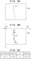
- FIGS. 5A to 5C are diagrams illustrating processing of detecting cracking as an example of a defect to be detected. For descriptive simplicity, FIGS. 5A to 5C illustrate a state in which only one crack is captured in a partial image.
- FIG. 5A illustrates a partial image 500 in which cracking 511 is captured.
- FIG. 5B illustrates defect information detected from the partial image 500.
- An example of FIG. 5B illustrates a state in which defect information 512 of the cracking 511 detected from the partial image 500 is displayed to be superimposed on the partial image 500 illustrated in FIG. 5A .
- the defect information 512 is configured as vector data associated with an image coordinate system 501 whose origin is set to be at a vertex 510 on the upper left corner of the partial image 500, and includes positions P1 to Pm.
- the positions P1 to Pm each include position coordinates of the image coordinate system, and the cracking is expressed by connecting each of the positions with a straight line.
- FIG. 5C illustrates a data structure of vector data of the defect information 512.
- the defect information 512 may be configured as raster data. In this case, the cracking is expressed by a group of positions of the image coordinate system.
- Methods for obtaining texture information from a partial image include, for example, a method of determination based on spatial frequency information of an image obtained by FFT.
- the learning processing may be executed by a graphics processing unit (GPU).
- the GPU is processor capable of performing processing specialized for computation of computer graphics, and has computational processing capabilities for performing matrix computations and the like necessary for learning processing in a short time.
- the learning processing is not limited to being performed in the GPU and a circuit configuration for performing matrix computations and the like necessary for a neural network need only be provided.
- a learned model and parameters to be used for the defect detection processing may be acquired via the network interface 307 from a cloud server and the like connected to a network.
- a configuration may be taken so as to transmit a detection image and parameters to a cloud server and acquire via the network interface 307 a result obtained by executing the defect detection processing using a learned model on the cloud server.
- the defect detection processing may be executed in parallel for a plurality of partial images.
- the image input unit 323 inputs a plurality of partial images in step S401
- the defect detection processing is executed in parallel by the detection processing unit 324 for each partial image
- a detection result for each partial image is acquired.
- the acquired detection result is outputted as vector data of the image coordinate system associated with each partial image.
- the identification information setting unit 325 generates and allocates unique identification information for each piece of defect information detected by the detection processing unit 324 in step S402. Unique means that there is no duplicate identification information in the defect information detected from partial images belonging to the same group. In the present embodiment, assume that partial images in which the same inspection target is captured are partial images of the same group.
- One method of generating identification information is, for example, a method of setting as a prefix a character string uniquely indicating a partial image and setting as identification information a character string for which the prefix and a serial number are concatenated.
- examples include, for example, a character string (ImageFileA 001, ImageFileA_002, ..., ImageFileB_001, ImageFileB_002, ...) for which a character string uniquely indicating a partial image (ImageFileA, ImageFileB, ...) is set as a prefix, an underscore (_) or a hyphen (-) is set as a concatenating character string, and a serial number for which a numerical value incrementing by one each time a defect is detected is concatenated at the end.
- a file path or a file name guaranteed to be unique in a file system may be used or an internal serial number may be given at the time of image input.
- a non-duplicate character string may be generated for each image using a known method of generating identification information, such as a UUID, or a known hash function.
- Another method of generating identification information is, for example, a method in which the identification information setting unit 325 accepts issuance of identification information in one queue and sequentially generates serial numbers while increasing the numerical value. Specifically, each time the detection processing unit 324 detects a defect, the detection processing unit 324 makes a request for issuance of identification information to the identification information setting unit 325, and serial number identification information, such as 1, 2, and 3, is returned in the order of request acceptance. In this case, a particular string may be combined with the serial number. Since the identification information setting unit 325 issues identification information different from identification information that has already been issued, it is maintained that the identification information is unique. Instead of a serial number, a known method of generating identification information, such as a UUID, may be used, or a unique hash value for which a known hash function is used may be used.
- the defect information detected from the partial image is first read into a design aid tool, such as CAD, in which the drawing information can be viewed. The user then needs to manually align a position and scale of the defect information with a partial image in the drawing information.
- CAD design aid tool
- the partial image corresponds to a single span of a deck of a bridge or a single span of a tunnel.
- software for viewing the drawing information may be configured such that that when the defect information including the outer shape information is brought close to a range of the partial image displayed together with the drawing, the defect information is automatically moved and transformed such that the defect information fits in the range of the partial image based on the outer shape information.
- the control unit 301 determines whether the processing from step S402 to step S405 has been executed for all the partial images inputted by the image input unit 323 in step S401. Then, when the processing has been completed, the control unit 301 proceeds to step S407, and when the processing has not been completed, the control unit 301 returns to step S402 and repeats the processing from step S402 to step S405.
- the output unit 327 outputs information obtained by adding the outer shape information of the partial images to the defect information detected from the partial images as a list of defect information.
- the list of defect information for example, is in a tabular format, such as CSV, or is general-purpose CAD data.
- the list of defect information includes an image coordinate system file for each partial image (a separate list of defect information) and a drawing coordinate system file in which a file for each partial image has been merged with each other for the entire structure to be inspected (a merged list of defect information); however, either one of these may be outputted depending on the application.
- a change of identification information may be applied according to a specific rule. For example, a character string (such as "MERGED _") indicating merging is added as a prefix to the beginning of the identification information.
- a rule for changing identification information is able to maintain a state in which identification information can be associated between the separate lists of defect information and the merged list of defect information. That is, the change rule is such that identification information of a defect can be derived from other identification information that indicates the same defect and identification information is not made to overlap with identification information of a list of defect information of a different group if the identification information is changed.
- defect information detected for each partial image can be managed in association with the drawing information and merged for the entire structure to be inspected. Further, the work of aligning the defect information to the drawing information is facilitated.
- identification information unique to defect information detected from a partial image is given, and a list of defect information in which outer shape information of the partial image is added is generated.
- a list of defect information in which defect information is offset in advance at regular intervals may be outputted.
- the defect information detected from the partial image for example, is represented by coordinate information of the image coordinate system with the upper left point of the partial image as the origin, and so, when the defect information is read into the drawing information by a design aid tool, such as a CAD, it is read into relatively the same position.
- the partial images are generated by capturing (or dividing) the structure to be inspected into rows or a grid at regular intervals. Therefore, the list of defect information may be such that coordinate information of the defect information is offset at regular intervals such that the partial images are arranged adjacent to each other.
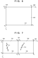
- FIG. 7 illustrates a state in which defect information 711 detected from a partial image 701 and outer shape information 722 of a partial image 702 are arranged to be offset in the same image coordinate system.
- the defect information 711 detected from the partial image 701 is represented by coordinate information of an image coordinate system 700 whose origin is an upper left vertex 750 of the partial image 701.
- outer shape information 721 of the partial image 701 is also represented by coordinate information of the image coordinate system 700.
- defect information 712 detected from the partial image 702 and the outer shape information 722 are represented not by the image coordinate system whose origin is the upper left vertex 750 of the partial image 701 but by coordinate information obtained by offsetting the origin to an upper left vertex 751 of the partial image 702.
- an offset distance is the width of the partial image 701 (the length from a point P1 to a point P4); however, the offset distance may be a distance obtained by multiplying a factor, such as 1.2, or a distance obtained by adding a constant value.
- FIG. 8 illustrates a UI screen in which an offset pattern can be selected by the user.
- the user can select any one of one row, n rows (n is inputted by the user), one column, and m columns (m is inputted by the user), and depending on the pattern specified by the user, a list of defect information in which coordinate information of defect information and outer shape information for each partial image is offset at regular intervals is outputted.
- a list of defect information for which coordinate information of defect information has been converted into coordinate information of drawing information is outputted according to information (a position and resolution of a partial image) necessary for coordinate transformation inputted by the user. This eliminates the need to perform the work of aligning defect information to drawing information by the user simply inputting information necessary for coordinate transformation and reading a list of defect information of the drawing coordinate system into the drawing information.
- Defect detection is performed on a partial image in which the same inspection target is recaptured after some time in order to investigate and record a change in defect over time.
- Defect detection is performed on a partial image in which an inspection target is recaptured with improvement in a condition, such as weather and resolution.
- Defect detection is performed again on the same partial image using more optimal parameters and a more optimal learned model.
- identification information of redetected defect information overlaps with identification information of other defect information detected in the past, it is difficult to manage the defect information in association with the drawing information. Therefore, in the present embodiment, identification information that does not overlap with other defect information detected in the past is given to the redetected defect information.
- a hardware configuration of the information processing apparatus 300 according to the second embodiment is similar to the configuration illustrated in FIG. 3A .
- FIG. 9 is a functional block diagram of the information processing apparatus 300 according to the second embodiment.
- a coordinate transformation unit 328 is added to the configuration illustrated in FIG. 3B .
- the coordinate transformation unit 328 performs processing for transforming coordinate information of defect information from the image coordinate system of a partial image to the drawing coordinate system of the drawing information.
- Each function of the information processing apparatus 300 is configured by hardware and/or software. A configuration may be taken such that each functional unit is configured by one or more computer apparatuses or server apparatuses, and these constitute a system connected by a network. Further when each functional unit illustrated in FIG. 9 is configured by hardware instead of being realized by software, there need only be provided a circuit configuration corresponding to each functional unit in FIG. 9 .
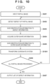
- the processing of FIG. 10 is realized by the control unit 301 of the information processing apparatus 300 illustrated in FIG. 3A operating as each of the functional units illustrated in FIG. 9 by controlling each of the components illustrated in FIG. 9 by loading and executing a computer program stored in the non-volatile memory 302 in the working memory 303. Further, the processing of FIG. 10 is started when the information processing apparatus 300 receives an instruction for starting defect detection processing by the input device 305.
- step S401 to step S405 the processing similar to that from step S401 to S405 of FIG. 4 is performed.
- step S1001 the coordinate transformation unit 328 converts the coordinate information of the defect information and the outer shape information of the partial image acquired in the processing from step S401 to step S405 from the image coordinate system to the drawing coordinate system.
- the coordinate information of the defect information is represented in the image coordinate system in which the origin is the upper left vertex of the partial image.
- the coordinate information of the image coordinate system is converted into the coordinate information of the drawing coordinate system.
- the information (partial image information) necessary for coordinate transformation is inputted by the user when the image input unit 323 inputs the partial image.
- the partial image information is, specifically, a position and resolution (scale) of the partial image in the drawing information.
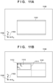
- FIG. 11A illustrates a drawing 1100 in which decking 1101 of a bridge is depicted as an example of infrastructure and a drawing coordinate system 1103 with a position 1102 as the origin.
- FIG. 11B illustrates a partial image 1111 in which a portion of the decking 1101 is captured and an image coordinate system 1113 in which an upper left vertex 1112 of the partial image 1111 is the origin.
- units of the image coordinate system 1113 are in pixels
- units of the drawing coordinate system 1103 are in meters.
- the defect information detected from the partial image 1111 is represented by the coordinate information of the image coordinate system 1113. This is converted into the coordinate information of the drawing coordinate system 1103.
- calculation can be performed based on a position of the origin 1112 of the image coordinate system 1113 represented by the coordinate information of the drawing coordinate system 1103 and a ratio of the units of the image coordinate system 1113 and the units of the drawing coordinate system 1103, that is, information of resolution (how many meters in the drawing coordinate system one pixel in the image coordinate system corresponds to).
- the list of defect information of the image coordinate system may be outputted together with the list of defect information represented by the drawing coordinate system.
- the list of defect information may be output to be divided for each partial image or may be outputted to be merged for each group.
- each time identification information is generated issued identification information is stored for each group, and when new identification information is generated, identification information that does not overlap with existing identification information of the same group is generated.
- the management unit 322 reads out information related to a group to which the partial image belongs and issued identification information from the storage unit 321, generates new identification information, and stores identification information issued for the group.
- identification information that is the same as existing identification information may be given.
- a known technique is used for comparison of new and old defect information, and a determination threshold is set. For example, coordinate information of new defect information and coordinate information of old defect information are compared and it is determined whether a difference therebetween is within a predetermined range, or when a length and angle of a line segment representing cracking has extended beyond a predetermined range in consideration of a change in a defect over time, it is determined that the same cracking has progressed.
- identification information is given to pieces of defect information which is considered to be equivalent, it is possible to use information related to identification information of existing defect information as it is, estimate a pace of deterioration of the structure by managing a change in a defect over time, and the like, thereby reducing the effort it takes to manage a defect of the structure to be inspected.
- the work of aligning redetected defect information for each partial image to the drawing information is facilitated, thereby making it possible for the redetected defect information to be managed in association with the drawing information.
- defect information of the entire structure to be inspected is collectively managed on a server, thereby making it possible to confirm or edit defect information using an individual viewer on site. Since high information processing capabilities and large screen output are not necessary for the individual viewer, inspection work can be performed using a portable terminal, such as a tablet.
- the drawing viewer is used when confirming and editing the defect of the entire structure to be inspected, such as when generating an inspection work report. Since editing work in each viewer is collected on the server, it is possible to support simultaneous editing according to inspection work by a plurality of persons.
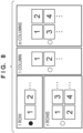
- FIG. 12 illustrates individual viewers 1201, 1202, and 1203 and a drawing viewer 1211.
- the individual viewer 1201 displays a partial image 1206, defect information 1205 displayed to be superimposed, and a list of defect information 1204.
- the drawing viewer 1211 displays a drawing 1212 of the structure to be inspected, defect information 1214 and 1215 displayed to be superimposed, and a list of defect information 1213.
- the individual viewer display an editing screen based on a list of defect information represented by the image coordinate system for each partial image.
- the drawing viewer display an editing screen based on a list of defect information represented by the drawing coordinate system of the structure to be inspected.
- the individual viewers 1201, 1202, and 1203 and the drawing viewer 1211 mutually synchronize information with each other. That is, content edited in the individual viewer is reflected in the list of defect information of the drawing viewer, and content edited in the drawing viewer is reflected in the list of defect information of the individual viewers.
- the user specifies a partial image to be displayed in the individual viewer.
- the individual viewer makes a request for with a list of defect information associated with the partial image specified by the user to the server, and the server transmits and to the individual viewer a partial image and a list of defect information to be transmitted to the individual viewer.
- the individual viewer stores this edited content.
- the individual viewer transmits edited content to the server.
- the server determines whether there is a conflict in the edited content with the drawing viewer and transmits the determination result to the individual viewer.
- the user performs editing again in the individual viewer to resolve the conflict and the re-edited content is transmitted to the server.
- Any of the known techniques may be used to resolve the conflict in edited content. It is also possible to prevent a conflict from occurring by an exclusive control mechanism, such as a check-out lock, without using a method of detecting a conflict in edited content and prompting the user to resolve the conflict.
- the user specifies using the drawing viewer a structure to be inspected that they want to display.
- the drawing viewer makes a request to the server for a list of defect information of the entire structure to be inspected, and the server transmits partial images of the structure to be inspected and a list of defect information to the drawing viewer in response to the request.
- the drawing viewer displays the partial images and defect information acquired from the server to be overlapped.
- the user confirms the defect information and inputs necessary information to the inspection report with the drawing viewer.
- the drawing viewer transmits edited content of the defect information to the server and similarly to the above-described individual viewer, performs each process of confirming the edited content, determining a conflict, and resolving the conflict.
- the drawing viewer outputs the inspection report in which the edited content has been reflected and ends the processing.
- Embodiment(s) of the present invention can also be realized by a computer of a system or apparatus that reads out and executes computer executable instructions (e.g., one or more programs) recorded on a storage medium (which may also be referred to more fully as a 'non-transitory computer-readable storage medium') to perform the functions of one or more of the above-described embodiment(s) and/or that includes one or more circuits (e.g., application specific integrated circuit (ASIC)) for performing the functions of one or more of the above-described embodiment(s), and by a method performed by the computer of the system or apparatus by, for example, reading out and executing the computer executable instructions from the storage medium to perform the functions of one or more of the above-described embodiment(s) and/or controlling the one or more circuits to perform the functions of one or more of the above-described embodiment(s).
- computer executable instructions e.g., one or more programs
- a storage medium which may also be referred to more fully as
- An information processing apparatus comprises an input unit that inputs one or more images belonging to a predetermined group, a detection unit that detects defect information based on an image inputted by the input unit, a setting unit that sets identification information that is unique within the predetermined group to the defect information detected by the detection unit, and an output unit that outputs a detection result including the defect information to which the identification information has been given by the setting unit.
Landscapes
- Engineering & Computer Science (AREA)
- Theoretical Computer Science (AREA)
- General Physics & Mathematics (AREA)
- Physics & Mathematics (AREA)
- Computer Vision & Pattern Recognition (AREA)
- Multimedia (AREA)
- Quality & Reliability (AREA)
- Software Systems (AREA)
- Signal Processing (AREA)
- Artificial Intelligence (AREA)
- Health & Medical Sciences (AREA)
- Medical Informatics (AREA)
- Evolutionary Computation (AREA)
- General Health & Medical Sciences (AREA)
- Computing Systems (AREA)
- Biochemistry (AREA)
- Pathology (AREA)
- Immunology (AREA)
- Databases & Information Systems (AREA)
- Analytical Chemistry (AREA)
- Chemical & Material Sciences (AREA)
- Life Sciences & Earth Sciences (AREA)
- Data Mining & Analysis (AREA)
- General Engineering & Computer Science (AREA)
- Mathematical Physics (AREA)
- Investigating Materials By The Use Of Optical Means Adapted For Particular Applications (AREA)
- Image Analysis (AREA)
Applications Claiming Priority (1)
| Application Number | Priority Date | Filing Date | Title |
|---|---|---|---|
| JP2022099048A JP2024000324A (ja) | 2022-06-20 | 2022-06-20 | 情報処理装置、情報処理方法及びプログラム |
Publications (1)
| Publication Number | Publication Date |
|---|---|
| EP4296956A1 true EP4296956A1 (en) | 2023-12-27 |
Family
ID=85726403
Family Applications (1)
| Application Number | Title | Priority Date | Filing Date |
|---|---|---|---|
| EP23163699.4A Pending EP4296956A1 (en) | 2022-06-20 | 2023-03-23 | Defect detection in partial images capturing an entire inspected infrastructure |
Country Status (4)
| Country | Link |
|---|---|
| US (1) | US20230410284A1 (https=) |
| EP (1) | EP4296956A1 (https=) |
| JP (1) | JP2024000324A (https=) |
| CN (1) | CN117274152A (https=) |
Families Citing this family (1)
| Publication number | Priority date | Publication date | Assignee | Title |
|---|---|---|---|---|
| JP7564671B2 (ja) | 2020-09-29 | 2024-10-09 | キヤノン株式会社 | 情報処理装置、制御方法、及び、プログラム |
Citations (5)
| Publication number | Priority date | Publication date | Assignee | Title |
|---|---|---|---|---|
| JP2005310044A (ja) | 2004-04-26 | 2005-11-04 | Constec Engi Co | データ処理装置、データ処理方法、及びデータ処理プログラム |
| JP5645730B2 (ja) | 2011-03-25 | 2014-12-24 | 公益財団法人鉄道総合技術研究所 | コンクリート表面の閉合ひび割れ検出方法 |
| JP6099479B2 (ja) | 2013-05-21 | 2017-03-22 | 大成建設株式会社 | ひび割れ検出方法 |
| WO2019021719A1 (ja) * | 2017-07-27 | 2019-01-31 | 富士フイルム株式会社 | 損傷データ編集装置、損傷データ編集方法、およびプログラム |
| US20210027450A1 (en) * | 2019-07-22 | 2021-01-28 | Canon Kabushiki Kaisha | Information processing apparatus, information processing method, and storage medium |
Family Cites Families (5)
| Publication number | Priority date | Publication date | Assignee | Title |
|---|---|---|---|---|
| JP6365799B2 (ja) * | 2016-06-17 | 2018-08-01 | 三菱電機株式会社 | 変状進展判定装置及び変状進展判定方法 |
| EP3748341A4 (en) * | 2018-02-02 | 2021-02-24 | Fujifilm Corporation | IMAGE PROCESSING DEVICE AND IMAGE PROCESSING METHOD |
| JP7344692B2 (ja) * | 2019-07-22 | 2023-09-14 | キヤノン株式会社 | 情報処理装置及び情報処理方法及びプログラム |
| EP4006792B1 (en) * | 2019-07-25 | 2025-06-25 | FUJIFILM Corporation | Repair diagram creating device, repair diagram creating method, and program |
| JP7433623B2 (ja) * | 2019-11-18 | 2024-02-20 | 株式会社ベイシスコンサルティング | 構造物画像管理システム |
-
2022
- 2022-06-20 JP JP2022099048A patent/JP2024000324A/ja active Pending
-
2023
- 2023-03-23 EP EP23163699.4A patent/EP4296956A1/en active Pending
- 2023-03-31 US US18/193,671 patent/US20230410284A1/en active Pending
- 2023-06-13 CN CN202310697230.7A patent/CN117274152A/zh active Pending
Patent Citations (5)
| Publication number | Priority date | Publication date | Assignee | Title |
|---|---|---|---|---|
| JP2005310044A (ja) | 2004-04-26 | 2005-11-04 | Constec Engi Co | データ処理装置、データ処理方法、及びデータ処理プログラム |
| JP5645730B2 (ja) | 2011-03-25 | 2014-12-24 | 公益財団法人鉄道総合技術研究所 | コンクリート表面の閉合ひび割れ検出方法 |
| JP6099479B2 (ja) | 2013-05-21 | 2017-03-22 | 大成建設株式会社 | ひび割れ検出方法 |
| WO2019021719A1 (ja) * | 2017-07-27 | 2019-01-31 | 富士フイルム株式会社 | 損傷データ編集装置、損傷データ編集方法、およびプログラム |
| US20210027450A1 (en) * | 2019-07-22 | 2021-01-28 | Canon Kabushiki Kaisha | Information processing apparatus, information processing method, and storage medium |
Also Published As
| Publication number | Publication date |
|---|---|
| US20230410284A1 (en) | 2023-12-21 |
| JP2024000324A (ja) | 2024-01-05 |
| CN117274152A (zh) | 2023-12-22 |
Similar Documents
| Publication | Publication Date | Title |
|---|---|---|
| CN115917610B (zh) | 设备管理方法、设备管理装置、设备管理程序、记录介质 | |
| US12106460B2 (en) | Information processing apparatus, information processing method, and non- transitory computer-readable storage medium | |
| CN111768483A (zh) | 信息处理设备和累积图像选择方法 | |
| WO2021262650A1 (en) | Systems and methods for automatic alignment of drawings | |
| EP4296956A1 (en) | Defect detection in partial images capturing an entire inspected infrastructure | |
| CN117553812A (zh) | 车道线的提取方法、存储介质与设备 | |
| US20240242333A1 (en) | Image processing apparatus and image processing method | |
| US20250124558A1 (en) | Information processing apparatus, information processing method, and non-transitory computer-readable storage medium | |
| JP2019200452A (ja) | 図面管理装置、図面管理方法及び図面管理プログラム | |
| EP4428783A1 (en) | Collaborative work support program, work support program, collaborative work support system and work support system | |
| CN112129227A (zh) | 一种印制电路板的扫描方法、装置、设备和介质 | |
| US12361533B2 (en) | Image processing apparatus and image processing method | |
| JP2019169182A (ja) | 情報処理装置、制御方法、プログラム | |
| JP2024035618A (ja) | 情報処理装置、情報処理方法およびプログラム | |
| Salah et al. | Predictive hybrid scan-to-BIM method improves heritage building documentation completeness and accuracy | |
| US20250225644A1 (en) | Information processing apparatus, information processing method, and non-transitory computer-readable storage medium storing a computer program | |
| EP4293620A1 (en) | Image processing apparatus, control method, storage medium, and program | |
| US20230368364A1 (en) | Image processing apparatus and control method | |
| CN120783344B (zh) | 点云局部质检标记方法、系统、程序产品、设备及介质 | |
| JP2024156382A (ja) | 情報処理装置、情報処理方法およびプログラム | |
| US20250200739A1 (en) | Information processing apparatus, information processing method, and non-transitory computer-readable medium | |
| US20250182720A1 (en) | Information processing apparatus and information processing method | |
| JP2025154553A (ja) | 画像処理装置、画像処理方法、及びプログラム | |
| JP2019213060A (ja) | 情報処理装置、その制御方法及びプログラム。 | |
| JP2025165140A (ja) | 情報処理方法及び情報処理システム |
Legal Events
| Date | Code | Title | Description |
|---|---|---|---|
| PUAI | Public reference made under article 153(3) epc to a published international application that has entered the european phase |
Free format text: ORIGINAL CODE: 0009012 |
|
| STAA | Information on the status of an ep patent application or granted ep patent |
Free format text: STATUS: THE APPLICATION HAS BEEN PUBLISHED |
|
| AK | Designated contracting states |
Kind code of ref document: A1 Designated state(s): AL AT BE BG CH CY CZ DE DK EE ES FI FR GB GR HR HU IE IS IT LI LT LU LV MC ME MK MT NL NO PL PT RO RS SE SI SK SM TR |
|
| STAA | Information on the status of an ep patent application or granted ep patent |
Free format text: STATUS: REQUEST FOR EXAMINATION WAS MADE |
|
| 17P | Request for examination filed |
Effective date: 20240627 |
|
| RBV | Designated contracting states (corrected) |
Designated state(s): AL AT BE BG CH CY CZ DE DK EE ES FI FR GB GR HR HU IE IS IT LI LT LU LV MC ME MK MT NL NO PL PT RO RS SE SI SK SM TR |
|
| STAA | Information on the status of an ep patent application or granted ep patent |
Free format text: STATUS: EXAMINATION IS IN PROGRESS |
|
| 17Q | First examination report despatched |
Effective date: 20250704 |