EP4296215B1 - Autonom fahrendes transportsystem zum transport von paletten und/oder gitterboxen und verfahren zum betrieb eines solchen autonom fahrenden transportsystems - Google Patents
Autonom fahrendes transportsystem zum transport von paletten und/oder gitterboxen und verfahren zum betrieb eines solchen autonom fahrenden transportsystems Download PDFInfo
- Publication number
- EP4296215B1 EP4296215B1 EP23179772.1A EP23179772A EP4296215B1 EP 4296215 B1 EP4296215 B1 EP 4296215B1 EP 23179772 A EP23179772 A EP 23179772A EP 4296215 B1 EP4296215 B1 EP 4296215B1
- Authority
- EP
- European Patent Office
- Prior art keywords
- transport system
- pallet
- sensor unit
- sensor
- free
- Prior art date
- Legal status (The legal status is an assumption and is not a legal conclusion. Google has not performed a legal analysis and makes no representation as to the accuracy of the status listed.)
- Active
Links
Images



Classifications
-
- B—PERFORMING OPERATIONS; TRANSPORTING
- B66—HOISTING; LIFTING; HAULING
- B66F—HOISTING, LIFTING, HAULING OR PUSHING, NOT OTHERWISE PROVIDED FOR, e.g. DEVICES WHICH APPLY A LIFTING OR PUSHING FORCE DIRECTLY TO THE SURFACE OF A LOAD
- B66F9/00—Devices for lifting or lowering bulky or heavy goods for loading or unloading purposes
- B66F9/06—Devices for lifting or lowering bulky or heavy goods for loading or unloading purposes movable, with their loads, on wheels or the like, e.g. fork-lift trucks
- B66F9/063—Automatically guided
-
- B—PERFORMING OPERATIONS; TRANSPORTING
- B66—HOISTING; LIFTING; HAULING
- B66F—HOISTING, LIFTING, HAULING OR PUSHING, NOT OTHERWISE PROVIDED FOR, e.g. DEVICES WHICH APPLY A LIFTING OR PUSHING FORCE DIRECTLY TO THE SURFACE OF A LOAD
- B66F17/00—Safety devices, e.g. for limiting or indicating lifting force
- B66F17/003—Safety devices, e.g. for limiting or indicating lifting force for fork-lift trucks
-
- B—PERFORMING OPERATIONS; TRANSPORTING
- B66—HOISTING; LIFTING; HAULING
- B66F—HOISTING, LIFTING, HAULING OR PUSHING, NOT OTHERWISE PROVIDED FOR, e.g. DEVICES WHICH APPLY A LIFTING OR PUSHING FORCE DIRECTLY TO THE SURFACE OF A LOAD
- B66F9/00—Devices for lifting or lowering bulky or heavy goods for loading or unloading purposes
- B66F9/06—Devices for lifting or lowering bulky or heavy goods for loading or unloading purposes movable, with their loads, on wheels or the like, e.g. fork-lift trucks
-
- B—PERFORMING OPERATIONS; TRANSPORTING
- B66—HOISTING; LIFTING; HAULING
- B66F—HOISTING, LIFTING, HAULING OR PUSHING, NOT OTHERWISE PROVIDED FOR, e.g. DEVICES WHICH APPLY A LIFTING OR PUSHING FORCE DIRECTLY TO THE SURFACE OF A LOAD
- B66F9/00—Devices for lifting or lowering bulky or heavy goods for loading or unloading purposes
- B66F9/06—Devices for lifting or lowering bulky or heavy goods for loading or unloading purposes movable, with their loads, on wheels or the like, e.g. fork-lift trucks
- B66F9/075—Constructional features or details
- B66F9/07504—Accessories, e.g. for towing, charging, locking
-
- B—PERFORMING OPERATIONS; TRANSPORTING
- B66—HOISTING; LIFTING; HAULING
- B66F—HOISTING, LIFTING, HAULING OR PUSHING, NOT OTHERWISE PROVIDED FOR, e.g. DEVICES WHICH APPLY A LIFTING OR PUSHING FORCE DIRECTLY TO THE SURFACE OF A LOAD
- B66F9/00—Devices for lifting or lowering bulky or heavy goods for loading or unloading purposes
- B66F9/06—Devices for lifting or lowering bulky or heavy goods for loading or unloading purposes movable, with their loads, on wheels or the like, e.g. fork-lift trucks
- B66F9/075—Constructional features or details
- B66F9/0755—Position control; Position detectors
-
- G—PHYSICS
- G01—MEASURING; TESTING
- G01S—RADIO DIRECTION-FINDING; RADIO NAVIGATION; DETERMINING DISTANCE OR VELOCITY BY USE OF RADIO WAVES; LOCATING OR PRESENCE-DETECTING BY USE OF THE REFLECTION OR RERADIATION OF RADIO WAVES; ANALOGOUS ARRANGEMENTS USING OTHER WAVES
- G01S17/00—Systems using the reflection or reradiation of electromagnetic waves other than radio waves, e.g. lidar systems
- G01S17/88—Lidar systems specially adapted for specific applications
- G01S17/93—Lidar systems specially adapted for specific applications for anti-collision purposes
- G01S17/931—Lidar systems specially adapted for specific applications for anti-collision purposes of land vehicles
-
- G—PHYSICS
- G05—CONTROLLING; REGULATING
- G05D—SYSTEMS FOR CONTROLLING OR REGULATING NON-ELECTRIC VARIABLES
- G05D1/00—Control of position, course, altitude or attitude of land, water, air or space vehicles, e.g. using automatic pilots
- G05D1/20—Control system inputs
- G05D1/24—Arrangements for determining position or orientation
- G05D1/242—Means based on the reflection of waves generated by the vehicle
- G05D1/2427—Means based on the reflection of waves generated by the vehicle for monitoring a zone of adjustable size or form
-
- G—PHYSICS
- G05—CONTROLLING; REGULATING
- G05D—SYSTEMS FOR CONTROLLING OR REGULATING NON-ELECTRIC VARIABLES
- G05D1/00—Control of position, course, altitude or attitude of land, water, air or space vehicles, e.g. using automatic pilots
- G05D1/60—Intended control result
- G05D1/617—Safety or protection, e.g. defining protection zones around obstacles or avoiding hazards
- G05D1/618—Safety or protection, e.g. defining protection zones around obstacles or avoiding hazards for cargo or occupants
-
- G—PHYSICS
- G05—CONTROLLING; REGULATING
- G05D—SYSTEMS FOR CONTROLLING OR REGULATING NON-ELECTRIC VARIABLES
- G05D1/00—Control of position, course, altitude or attitude of land, water, air or space vehicles, e.g. using automatic pilots
- G05D1/60—Intended control result
- G05D1/656—Interaction with payloads or external entities
- G05D1/667—Delivering or retrieving payloads
-
- G—PHYSICS
- G05—CONTROLLING; REGULATING
- G05D—SYSTEMS FOR CONTROLLING OR REGULATING NON-ELECTRIC VARIABLES
- G05D2105/00—Specific applications of the controlled vehicles
- G05D2105/20—Specific applications of the controlled vehicles for transportation
- G05D2105/28—Specific applications of the controlled vehicles for transportation of freight
-
- G—PHYSICS
- G05—CONTROLLING; REGULATING
- G05D—SYSTEMS FOR CONTROLLING OR REGULATING NON-ELECTRIC VARIABLES
- G05D2107/00—Specific environments of the controlled vehicles
- G05D2107/70—Industrial sites, e.g. warehouses or factories
-
- G—PHYSICS
- G05—CONTROLLING; REGULATING
- G05D—SYSTEMS FOR CONTROLLING OR REGULATING NON-ELECTRIC VARIABLES
- G05D2109/00—Types of controlled vehicles
- G05D2109/10—Land vehicles
Definitions
- the invention relates to an autonomously driving transport system, in particular an autonomously driving stacker, in particular in the form of a forklift truck for transporting pallets and/or lattice boxes, and a method for operating such an autonomously driving transport system.
- an autonomously driving transport system in particular an autonomously driving stacker, in particular in the form of a forklift truck for transporting pallets and/or lattice boxes, and a method for operating such an autonomously driving transport system.
- pallets with goods or wire mesh boxes with goods are lined up next to each other to save space.
- the pallet or wire mesh box is pushed into a free space (free storage area).
- AGVs autonomous vehicles
- the pallets or wire mesh boxes are placed next to each other in such a way that an escape route is still available for the person. Often, a full space is left free next to a parked pallet or wire mesh box. This storage space can then no longer be used.
- the DE 10 2019 215 180 A1 describes an autonomously driving vehicle for
- the CN 113 703 460 A shows an autonomously driving transport system.
- the transport system receives a corresponding unloading command and then travels to a target area.
- the transport system includes an obstacle detection device that continuously monitors the route for obstacles. If no obstacle is detected in the target areas, a parking mode is entered and the transport system travels into the target area.
- the DE 10 2020 102 513 A1 describes a driverless transport system for transporting workpieces.
- the monitoring area for detecting obstacles is adjustable in size.
- WO 2021/069674 A1 Describes an autonomous vehicle with a sensor system for obstacle detection and navigation.
- the vehicle uses a variety of sensors, including LiDAR and cameras, to monitor its surroundings and ensure safe movement.
- the vehicle's control unit can process the sensor data to calculate the optimal path and avoid obstacles.
- the US 2020 /101971 A1 Describes a collision avoidance system for an autonomous transport system.
- An obstacle detection system can detect objects.
- a control unit defines boundary areas to determine whether the detected object is within such a boundary area. If so, an alarm is issued.
- Claim 10 describes a method for operating a such an autonomously driving transport system.
- Claims 2 to 9 describe inventive developments of the autonomously driving transport system.
- the autonomously driving transport system is used in particular for transporting pallets and/or wire mesh boxes.
- the transport system comprises a receiving device for receiving such a pallet and/or wire mesh box.
- the transport system further comprises a drive unit and a control device.
- the control device has a data processing unit and an obstacle detection device with a first sensor unit.
- the obstacle detection device is designed via the first sensor unit to generate a monitoring field in order to use the monitoring field to examine a free parking area for the pallet and/or wire mesh box between other pallets and/or wire mesh boxes for obstacles.
- the control device is designed to control the drive unit such that the transport system (in the absence of an obstacle) assumes a parking operating mode and moves the pallet and/or wire mesh box into the free parking area for parking.
- the obstacle detection device is configured in the parking mode to deactivate the monitoring field or not output an obstacle detection signal while driving through the free parking area, at least until the pallet and/or the wire mesh box is parked on the free parking area. This is achieved by appropriately controlling the first sensor unit.
- the data processing unit is configured in the parking mode to ignore an obstacle detection signal from the obstacle detection device while driving through the free parking area, at least until the pallet and/or the wire mesh box is parked on the free parking area.
- the autonomous transport system is, in particular, a self-driving and self-navigating vehicle.
- the transport system is preferably used for the automatic picking up and unloading of loads (e.g. pallets and lattice boxes mentioned herein).
- loads e.g. pallets and lattice boxes mentioned herein.
- the transport system can be, for example, an industrial truck or a stacker, in particular in the form of a forklift.
- the autonomously driving transport system first uses a monitoring field to detect whether there are any obstacles on a free parking area for the pallet and/or the wire mesh box. If there are no obstacles (e.g. people or objects) on the free parking area, the transport system switches to the parking mode. In this parking mode, for example, the monitoring field can be deactivated. The distance traveled can be monitored to ensure that the transport system does not exceed the cleared area. Alternatively, no obstacle detection signal is emitted despite the monitoring field being activated, or such an obstacle detection signal is ignored and the journey continues. This is easily possible because the free parking area has already been checked for obstacles before entering it. These are two measures that allow for more efficient use of the storage space.
- the free parking space is scanned with a monitoring field immediately before entering the free parking space, and on the other hand, it is ensured that no safety reaction of the obstacle detection device is triggered, which would interrupt the parking process and the pallets and/or wire mesh boxes can therefore be parked very close to one another.
- the wording "immediately" means in particular that the free parking space is checked for obstacles less than 10 seconds, 5 seconds, or less than 3 seconds before entering, in order to ensure that no person enters it.
- other sensor units that are also used for this purpose designed to detect obstacles and which are not used to monitor the free parking space, remain activated in order to detect persons who approach the autonomous transport system and possibly attempt to pass the side of the autonomous transport system into the free parking space. Upon such detection, the autonomous transport system preferably stops or leaves the free parking space again.
- control device is designed to control the drive unit in such a way that the transport system, in parking mode, only travels within the cleared area of the parking area. This prevents collisions even when the obstacle detection device is deactivated.
- the first sensor unit is an optical sensor, an acoustic sensor (e.g., ultrasound), or an electromagnetic sensor (e.g., radar).
- the optical sensor is a ToF (time-of-flight) sensor and/or a laser scanner. This allows the unoccupied parking area to be scanned for obstacles with high resolution.
- the receiving device comprises forks.
- the transport system is a forklift.
- the first sensor unit is arranged at the end of at least one fork. This makes it particularly easy to check the free parking space for obstacles.
- the fork could be hollow to accommodate connecting cables between the first sensor unit and the data processing unit.
- the first sensor unit is arranged in a lower region of the transport system.
- the first sensor unit is arranged on the side of the transport system on which the receiving device is also located.
- the control device is designed to control the receiving device in such a way that it lifts the pallet and/or the wire mesh box so that the monitoring field of the first sensor unit extends underneath the pallet and/or the wire mesh box towards the free parking area in order to thereby examine it for obstacles. This lifting can preferably only take place before driving onto the free parking area. To drive onto the free parking area, the pallet and/or the wire mesh box could already be lowered again (e.g. in the alternative with the deactivated monitoring field).
- the obstacle detection device comprises a second sensor unit.
- the first sensor unit is arranged at the rear of the transport system and the second sensor unit is arranged at the front of the transport system. This allows both during forward travel (here the second sensor unit is used) and during reverse travel (here the first sensor unit used) an obstacle in the respective direction of travel is detected.
- the drive unit is an electric drive unit.
- the control device is designed to monitor the current consumption of the drive unit. In the event that the current consumption of the drive unit exceeds a threshold value, the control device is designed to control the drive unit in such a way that it stops the transport system or moves out of the free parking area.
- the current consumption can be an indication of a possible collision.
- the control device it would be conceivable for the control device to adjust the threshold value depending on the weight of the picked-up pallet and/or wire mesh box. For heavier pallets and/or wire mesh boxes, the threshold value is higher than for lighter pallets and/or wire mesh boxes. This introduces an additional safety factor.
- control device is designed to reduce the speed at which the autonomously driving transport system travels through the free parking area compared to a speed at which the autonomously driving transport system is otherwise moved.
- the speed at which the autonomously driving transport system travels through the free parking area is less than 1 m/s, 50 cm/s, or less than 30 cm/s.
- the method according to the invention is used to operate an autonomously moving transport system for transporting pallets and/or wire mesh boxes.
- a monitoring field is generated. This is preferably carried out by a first sensor unit of an obstacle detection device. This monitoring field is used to determine a free parking space for a pallet and/or wire mesh box (which the transport system carries) between other
- Pallets and/or wire mesh boxes are inspected for obstacles (people and/or objects).
- the drive unit is controlled in such a way that if there is no obstacle (the monitoring field detects no obstacle in the free parking area), the transport system enters a parking mode and the pallet and/or wire mesh box moves into the free parking area for parking. This control is preferably carried out by the control device.
- the monitoring field is deactivated. Alternatively, an obstacle detection signal is prevented from being output (in particular, passed on to the data processing unit). Alternatively, such an obstacle detection signal is ignored (by the data processing unit) as long as the transport system is in parking mode.
- Figure 1A shows an embodiment of an autonomously driving transport system according to the invention, here in the form of a forklift 1.
- the forklift 1 is preferably used to transport pallets 2 and/or wire mesh boxes.
- the forklift 1 preferably comprises two forks 3.
- various goods 4 are arranged on the pallets 2.
- the pallets 2 are arranged in two columns.
- a first column comprises three pallets 2 and a second column comprises two pallets 2.
- In the second column there is therefore a free storage area 5.
- This free storage area 5 is bordered on three sides by other pallets 2. If the free storage area 5 is now used to store another pallet 2, there is no escape route for any person who is on the free storage area 5 when this additional pallet 2 is driven in, for example to sort goods 4 on one of the adjacent pallets 2.
- the forklift 1 comprises a drive unit (not shown). This is preferably an electric drive unit, which is driven, for example, inductively (e.g. via at least one conductor track in the floor) or via a battery.
- the forklift 1 also comprises a control device (not shown) which has a data processing unit (not shown) and an obstacle detection device 6.
- the obstacle detection device 6 comprises a first sensor unit 7a and a second sensor unit 7b (see Figures 2A, 2B, 2C).
- the first sensor unit 7a is arranged at the rear of the forklift 1, i.e. where the forks 3 are attached.
- the second sensor unit 7b is arranged at the front of the forklift 1.
- the forklift 1 is designed to move with the front in the direction of travel to the destination after picking up a pallet 2 and/or wire mesh box. This has the advantage that the pallet 2 and/or wire mesh box does not cover the second sensor unit 7b of the obstacle detection device 6, which detects obstacles in front of the forklift 1.
- the first sensor unit 7a and/or the second sensor unit 7b comprise at least one optical sensor, at least one acoustic sensor, or at least one electromagnetic sensor. It would be conceivable for the first sensor unit 7a and the second sensor unit 7b to comprise different types of sensors. It would also be conceivable for the first sensor unit 7a and the second sensor unit 7b to comprise a different number of sensors.
- the optical sensor is preferably a ToF sensor and/or a laser scanner. Obstacles in the vicinity of forklift truck 1 can be detected using the light propagation times between an emitted light pulse and a received light pulse reflected by an obstacle.
- the first sensor unit 7a is designed to generate a monitoring field 8.
- the second sensor unit 7b is also designed to generate a monitoring field 8.
- the monitoring fields 8 of the first sensor unit 7a and the second sensor unit 7b can be the same size or different sizes.
- the first sensor unit 7a is designed to use its monitoring field 8 to examine the free parking area 5 for the pallet 2 and/or wire mesh box to be parked between other pallets 2 for obstacles.
- the monitoring field 8 is shown hatched in this case.
- the shape of the monitoring field 8 is chosen only as an example and is intended merely to clarify that the monitoring field 8 is directed towards the free parking area 5.
- the monitoring field 8 preferably extends close to the ground. This means that a distance between the ground and the monitoring field 8 is preferably less than 80 cm, 50 cm, 40 cm or less than 20 cm.
- the monitoring field 8 preferably runs approximately parallel to the ground.
- the wording "approximately" preferably also includes deviations of less than 10° or less than 5°. It would also be conceivable for the monitoring field 8 to strike the ground of the free parking area 5 at an angle.
- the control device of the forklift 1 is designed to control the drive unit such that the forklift 1 enters a parking mode in the absence of an obstacle.
- the forklift 1 moves the pallet 2 and/or the wire mesh box into the free parking area 5 for parking.
- the obstacle detection device 6 is designed to deactivate the monitoring field 8 while driving through the free parking area 5, at least until the pallet 2 and/or the wire mesh box is parked on the free parking area 5. This can be done, for example, by interrupting the power supply to the first sensor unit 7a or by applying a corresponding control signal to the first sensor unit 7a. This situation is described in Figure 1B shown.
- the obstacle detection device 6 is designed to monitor the monitoring field 8 during travel on the free parking area 5, at least until the pallet 2 and/or the wire mesh box is placed on the free parking area 5. to be limited to the free parking space 5.
- the data processing unit is designed to control the first sensor unit 7a in such a way that it limits its monitoring field 8 to the part of the free parking area 5 that has not yet been traveled.
- the forklift truck 1 preferably comprises a sensor unit for this purpose.
- the sensor unit is designed to continuously determine a traveled distance in the parking mode, wherein the obstacle detection device 6 is designed to continuously limit, i.e., reduce, the monitoring field 8 (of the first sensor unit 7a) based on the determined distance.
- the “limiting” occurs in such a way that neighboring pallets 2 and/or wire mesh boxes do not generate an obstacle detection signal.
- the sensor unit is preferably designed as a rotary encoder and arranged on a drive shaft of the drive unit.
- the obstacle detection device 6 is designed to limit the monitoring field 8 (of the first sensor unit 7a) by adjusting the radiation angle of the first sensor unit 7a. This could be achieved, for example, by tilting the first sensor unit 7a or by rotating a mirror within the first sensor unit 7a. The further the forklift truck 1 travels into the free parking area 5, the greater the angle between the monitoring field 8 and the ground could be.
- Limiting could also be achieved by configuring the obstacle detection device 6 or the data processing unit to limit the monitoring field 8 by masking out certain areas that extend beyond the free parking area 5. This could be achieved by ignoring reflected light pulses that arrive after a certain time. In this case, light pulses reflected by neighboring pallets 2 and/or wire mesh boxes could be ignored.
- the obstacle detection device 6 is designed to detect obstacles while driving on the free parking area 5, at least until the picked-up pallet 2 and/or the picked up grid box on the free storage area 5, no obstacle detection signal is issued.
- the data processing unit prefferably, the data processing unit to be designed to ignore an obstacle detection signal from the obstacle detection device 6 while driving across the free parking area 5, at least until the pallet 2 and/or the wire mesh box is parked on the free parking area 5.
- the obstacle detection device 6 is connected to the data processing unit. This can be done via an electrical or optical connection. A wireless connection would also be conceivable.
- the data processing unit which is part of the control device, is preferably designed to inform the obstacle detection device 6 that it should deactivate the monitoring field 8 of the first sensor unit 7a accordingly or that it should not output an obstacle detection signal. The data processing unit could also simply ignore such an obstacle detection signal in the parking mode.
- the data processing unit is configured to control the obstacle detection device 6 such that either the first sensor unit 7a or the second sensor unit 7b is activated (generating a monitoring field 8), which is arranged at the front of the forklift 1 in the direction of travel. If the forklift 1 travels forward, the second sensor unit 7b is activated. If the forklift 1 travels backward, the first sensor unit 7a is activated. The other sensor unit 7a or 7b is then preferably deactivated, or corresponding obstacle detection signals do not trigger a trigger reaction.
- the first sensor unit 7a and the second sensor unit 7b can be mounted on the forklift 1.
- the first sensor unit 7a is located at a lower area of the forklift 1
- the control device is designed to control the picking device in such a way that it lifts the picked-up pallet 2 and/or the picked-up wire mesh box, so that the monitoring field 8 of the first sensor unit 7a extends beneath the picked-up pallet 2 and/or beneath the picked-up wire mesh box in the direction of the free storage area 5. This reliably prevents pallets 2 or wire mesh boxes loaded with goods 4 from obscuring the monitoring field 8.
- the first sensor unit 7a could additionally be arranged at a distance from the underbody of the forklift truck 1 in the direction of the ground (roadway), so that the picking device only has to lift the picked-up pallet and/or the picked-up wire mesh box minimally (preferably less than 50 cm, 40 cm, 30 cm or less than 20 cm).
- the monitoring field 8 of the second sensor unit 7b is not obscured by a receiving device and the pallet 2 and/or pallet cage picked up by the receiving device.
- the first sensor unit 7a it would be conceivable for the first sensor unit 7a to be arranged closer to the ground than the second sensor unit 7b.
- the first sensor unit 6a is arranged at one end of at least one fork 3. This measure also ensures that the monitoring field 8 is not covered by the picked-up pallet 2 and/or the picked-up wire mesh box.
- Figure 3 describes a method for operating the autonomously driving forklift truck 1.
- a monitoring field 8 is generated by the first sensor unit 7a in order to use this monitoring field 8 to examine the free parking area 5 for the pallet 2 to be parked and/or the wire mesh box to be parked between other pallets 2 and/or wire mesh boxes for obstacles.
- the drive unit is controlled by the control device in such a way that the forklift truck 1, in the absence of an obstacle (not detected), enters a parking mode and moves the picked-up pallet 2 and/or the picked-up wire mesh box into the free parking area 5 for parking.
- the monitoring field 8 of the first sensor unit 7a is deactivated.
- the first sensor unit 7a or the obstacle detection device 6 is prevented from outputting an obstacle detection signal, or an output obstacle detection signal is ignored (in particular by the data processing unit).
- the third method step S 3 is carried out, in particular, as long as the forklift truck is in parking mode. Once the forklift truck 1 has deposited the picked-up pallet 2 and/or the picked-up wire mesh box, it moves out of the free parking area 5. In this case, at least the second sensor unit 7b is activated.
- the first sensor unit 7a can also be reactivated, or corresponding obstacle detection signals from the first sensor unit 7a again lead to a trigger reaction.
- the control device monitors, based on a signal from the encoder unit and/or another position signal, that the maximum distance traveled is less than or equal to the depth of the previously measured area, ie the forklift truck 1 does not travel beyond the measured area (ie the free parking area 5).
- the data processing unit is part of the control device and/or part of the obstacle detection device 6.
Landscapes
- Engineering & Computer Science (AREA)
- Structural Engineering (AREA)
- Transportation (AREA)
- Life Sciences & Earth Sciences (AREA)
- Geology (AREA)
- Mechanical Engineering (AREA)
- Civil Engineering (AREA)
- Physics & Mathematics (AREA)
- Radar, Positioning & Navigation (AREA)
- Remote Sensing (AREA)
- General Physics & Mathematics (AREA)
- Aviation & Aerospace Engineering (AREA)
- Automation & Control Theory (AREA)
- Computer Networks & Wireless Communication (AREA)
- Electromagnetism (AREA)
- Control Of Position, Course, Altitude, Or Attitude Of Moving Bodies (AREA)
- Warehouses Or Storage Devices (AREA)
Description
- Die Erfindung betrifft ein autonom fahrendes Transportsystem, insbesondere einen autonom fahrenden Stapler, insbesondere in Form eines Gabelstaplers zum Transport von Paletten und/oder Gitterboxen und ein Verfahren zum Betrieb eines solchen autonom fahrenden Transportsystems.
- Paletten mit Gütern bzw. Gitterboxen mit Gütern werden in der Produktion bzw. Logistik platzsparend nebeneinander aufgereiht. Hierzu wird die Palette bzw. die Gitterbox in einen freien Platz (freie Abstellfläche) geschoben. Neuerdings erfolgt dies auch automatisiert mittels autonom fahrenden Fahrzeugen (AGV - Automated Guided Vehicle). Um sicherzustellen, dass keine Person verletzt wird, die sich auf dem freien Platz befindet, werden die Paletten bzw. Gitterboxen derart nebeneinander abgestellt, dass das noch ein Fluchtweg für die Person vorhanden ist. Häufig wird neben einer abgestellten Palette bzw. Gitterbox ein voller Platz freigelassen. Dieser Lagerplatz kann dann nicht weiter verwendet werden.
- Die
DE 10 2019 215 180 A1 beschreibt ein autonom fahrendes Fahrzeug zum - Transport von Lasten nach dem Oberbegriff des Anspruchs 1. Zum Abladen der Last auf einer freien Abstellfläche fährt das Fahrzeug rückwärts, wobei eine Sensoreinrichtung die freie Abstellfläche auf Hindernisse untersucht. Löst ein Warnfeld beim Rückwärtsfahren in die freie Abstellfläche aus, so schaltet die Sensoreinrichtung auf ein schmaleres Schutzfeld um. Durch dieses schmalere Schutzfeld können eingeschlossene Personen erkannt werden.
- Die
CN 113 703 460 A zeigt ein autonom fahrendes Transportsystem. Das Transportsystem empfängt einen entsprechenden Entladebefehl und fährt dann zu einem Zielgebiet. Das Transportsystem umfasst eine Hinderniserkennungseinrichtung, die den Fahrweg permanent nach Hindernissen überwacht. Wird kein Hindernis in Zielgebiete detektiert, so wird ein Abstellbetriebsmodus eingenommen und das Transportsystem fährt in das Zielgebiet hinein. - Die
DE 10 2020 102 513 A1 beschreibt ein fahrerloses Transportsystem zum Transportieren von Werkstücken. Der Überwachungsbereich zum Detektieren von Hindernissen ist dabei in seiner Größe anpassbar. -
WO 2021/069674 A1 beschreibt ein autonomes Fahrzeug mit einer Sensoreinrichtung zur Erkennung von Hindernissen und zur Navigation. Das Fahrzeug verwendet eine Vielzahl von Sensoren, darunter LiDAR und Kameras, um die Umgebung zu überwachen und eine sichere Bewegung zu gewährleisten. Die Steuerungseinheit des Fahrzeugs kann die Daten der Sensoren verarbeiten, um den optimalen Pfad zu berechnen und Hindernisse zu vermeiden. - Die
US 2020 /101971 A1 beschreibt ein System zur Kollisionsvermeidung eines autonom fahrenden Transportsystems. Über ein Hinderniserkennungssystem können Objekte detektiert werden. Eine Steuereinheit legt Grenzbereiche fest um zu ermitteln, ob sich das detektierte Objekt innerhalb eines solchen Grenzbereichs befindet. Ist dies der Fall, so wird ein Alarm ausgegeben. - Es ist daher die Aufgabe der hier vorliegenden Erfindung ein autonom fahrendes Transportsystem zum Transport von Paletten und/oder Gitterboxen zu schaffen, durch das der vorhandene Lagerplatz möglichst effizient genutzt werden kann.
- Die Aufgabe wird durch das autonom fahrende Transportsystem des unabhängigen Anspruchs 1 gelöst. Anspruch 10 beschreibt ein Verfahren zum Betrieb eines solchen autonom fahrenden Transportsystems. Die Ansprüche 2 bis 9 geben erfindungsgemäße Weiterbildungen des autonom fahrenden Transportsystems wieder.
- Das erfindungsgemäße autonom fahrende Transportsystem dient insbesondere zum Transport von Paletten und/oder Gitterboxen. Das Transportsystem umfasst eine Aufnahmevorrichtung zur Aufnahme einer solchen Palette und/oder Gitterbox. Das Transportsystem umfasst weiterhin eine Antriebseinheit und eine Steuervorrichtung. Die Steuervorrichtung weist eine Datenverarbeitungseinheit und eine Hinderniserkennungseinrichtung mit einer ersten Sensoreinheit auf. Die Hinderniserkennungseinrichtung ist über die erste Sensoreinheit dazu ausgebildet, um ein Überwachungsfeld zu erzeugen, um mit dem Überwachungsfeld eine freie Abstellfläche für die Palette und/oder die Gitterbox zwischen anderen Paletten und/oder Gitterboxen auf Hindernisse hin zu untersuchen. Die Steuervorrichtung ist dazu ausgebildet, um die Antriebseinheit derart anzusteuern, dass das Transportsystem (bei einem fehlenden Hindernis) einen Abstellbetriebsmodus einnimmt und die Palette und/oder die Gitterbox zum Abstellen in die freie Abstellfläche fährt. In einer ersten Alternative ist die Hinderniserkennungseinrichtung im Abstellbetriebsmodus dazu ausgebildet, um während des Befahrens der freien Abstellfläche, zumindest bis zum Abstellen der Palette und/oder der Gitterbox auf der freien Abstellfläche, das Überwachungsfeld zu deaktivieren oder kein Hinderniserkennungssignal auszugeben. Dies erfolgt durch entsprechende Ansteuerung der ersten Sensoreinheit. In einer anderen Alternative ist die Datenverarbeitungseinheit im Abstellbetriebsmodus dazu ausgebildet, um während des Befahrens der freien Abstellfläche, zumindest bis zum Abstellen der Palette und/oder der Gitterbox auf der freien Abstellfläche, ein Hinderniserkennungssignal der Hinderniserkennungseinrichtung zu ignorieren.
- Bei dem autonom fahrenden Transportsystem handelt es sich insbesondere um ein selbstfahrendes und selbstnavigierendes Fahrzeug. Das Transportsystem ist bevorzugt zum automatischen Aufnehmen und Abladen von Lasten (d.h. z.B. der hierin genannten Paletten und Gitterboxen) ausgebildet. Das Transportsystem kann z.B. ein Flurförderzeug oder ein Stapler sein, insbesondere in Form eines Gabelstaplers.
- Es ist besonders vorteilhaft, dass das erfindungsgemäße autonom fahrende Transportsystem zuerst mittels eines Überwachungsfeldes detektiert, ob sich Hindernisse auf einer freien Abstellfläche für die Palette und/oder die Gitterbox befinden. Befinden sich keine Hindernisse (zum Beispiel Personen oder Gegenstände) auf der freien Abstellfläche, so wechselt das Transportsystem in den Abstellbetriebsmodus. In diesem Abstellbetriebsmodus kann beispielsweise das Überwachungsfeld deaktiviert werden. Dabei kann die gefahrene Distanz überwacht werden, so dass sichergestellt wird, dass das Transportsystem nicht über die freigemessene Fläche hinausfährt. Alternativ wird trotz aktiviertem Überwachungsfeld kein Hinderniserkennungssignal ausgegeben bzw. ein solches Hinderniserkennungssignal wird ignoriert und die Fahrt wird fortgesetzt. Diese ist problemlos möglich, weil vor dem Einfahren in die freie Abstellfläche diese bereits auf Hindernisse hin untersucht wurde. Es sind daher zwei Maßnahmen, die eine effizientere Nutzung des Lagerplatzes erlauben. Einerseits wird die freie Abstellfläche mit einem Überwachungsfeld unmittelbar vor Befahren der freien Abstellfläche gescannt und andererseits wird dafür Sorge getragen, dass keine Sicherheitsreaktion der Hinderniserkennungseinrichtung ausgelöst wird, was den Abstellvorgang unterbrechen würde und die Paletten und/oder Gitterboxen daher sehr eng zueinander abgestellt werden können. Der Wortlaut "unmittelbar" bedeutet insbesondere, dass die freie Abstellfläche weniger als 10 Sekunden, 5 Sekunden oder weniger als 3 Sekunden vor Befahren auf Hindernisse untersucht wird, um dadurch sicherzustellen, dass sich nicht noch eine Person hinein bewegt. Weiter vorzugsweise können andere Sensoreinheiten, die ebenfalls dazu ausgebildet sind, um Hindernisse zu detektieren und die nicht zur Überwachung der freien Abstellfläche dienen, aktiviert bleiben, um dadurch Personen detektieren zu können, die sich dem autonom fahrenden Transportsystem nähern und gegebenenfalls versuchen seitlich an dem autonom fahrenden Transportsystem vorbei in die freie Abstellfläche zu gelangen. Bei einer solchen Detektion hält das autonom fahrende Transportsystem vorzugsweise an oder verlässt die freie Abstellfläche wieder.
- In einer vorteilhaften Ausführungsform ist die Steuervorrichtung dazu ausgebildet, um die Antriebseinheit derart anzusteuern, dass das Transportsystem im Abstellbetriebsmodus nur auf dem freigemessenen Bereich der Abstellfläche fährt. Dadurch werden Kollisionen auch dann verhindert, wenn die Hinderniserkennungseinrichtung deaktiviert ist.
- In einer weiteren vorteilhaften Ausführungsform handelt es sich bei der ersten Sensoreinheit um einen optischen Sensor, einen akustischen Sensor (z.B. Ultraschall) oder einen elektromagnetischen Sensor (z.B. Radar). Bevorzugt handelt sich bei dem optischen Sensor um einen ToF-Sensor (Time-of-Flight) und/oder einen Laserscanner. Dadurch kann die freie Abstellfläche mit einer hohen Auflösung auf Hindernisse hin untersucht werden.
- In einer weiteren vorteilhaften Ausführungsform umfasst die Aufnahmevorrichtung Gabeln. In diesem Fall handelt es sich bei dem Transportsystem um einen Gabelstapler.
- In einer weiteren vorteilhaften Ausführungsform ist die erste Sensoreinheit am Ende zumindest einer Gabel angeordnet. Dadurch kann die freie Abstellfläche besonders einfach auf Hindernisse hin untersucht werden. Die Gabel könnte entsprechend hohl sein, um Verbindungskabel zwischen der ersten Sensoreinheit und der Datenverarbeitungseinheit aufzunehmen.
- In einer weiteren vorteilhaften Ausführungsform ist die erste Sensoreinheit an einem unteren Bereich des Transportsystems angeordnet. Insbesondere ist die erste Sensoreinheit auf der Seite des Transportsystems angeordnet, auf welcher sich auch die Aufnahmevorrichtung befindet. Die Steuervorrichtung ist dazu ausgebildet, um die Aufnahmevorrichtung derart anzusteuern, dass diese die Palette und/oder die Gitterbox anhebt, sodass sich das Überwachungsfeld der ersten Sensoreinheit unterhalb der Palette und/oder der Gitterbox hindurch in Richtung der freien Abstellfläche erstreckt, um diese dadurch auf Hindernisse hin zu untersuchen. Dieses Anheben kann bevorzugt lediglich vor dem Befahren der freien Abstellfläche erfolgen. Zum Befahren der freien Abstellfläche könnte die Palette und/oder die Gitterbox bereits wieder abgesenkt werden (z.B. bei der Alternative mit dem deaktivierten Überwachungsfeld).
- In einer weiteren vorteilhaften Ausführungsform umfasst die Hinderniserkennungseinrichtung eine zweite Sensoreinheit. Die erste Sensoreinheit ist rückseitig am Transportsystem und die zweite Sensoreinheit frontseitig am Transportsystem angeordnet. Dadurch kann sowohl in einer Vorwärtsfahrt (hier wird die zweite Sensoreinheit verwendet) als auch bei einer Rückwärtsfahrt (hier wird die erste Sensoreinheit verwendet) ein Hindernis in der jeweiligen Fahrtrichtung erkannt werden.
- In einer weiteren vorteilhaften Ausführungsform ist die Antriebseinheit eine elektrische Antriebseinheit. Die Steuervorrichtung ist im Abstellbetriebsmodus dazu ausgebildet, um die Stromaufnahme der Antriebseinheit zu überwachen. Für den Fall, dass die Stromaufnahme der Antriebseinheit einen Schwellenwert überschreitet, ist die Steuervorrichtung dazu ausgebildet, um die Antriebseinheit derart anzusteuern, dass diese das Transportsystem stoppt oder aus der freien Abstellfläche herausfährt. Die Stromaufnahme kann ein Indiz für eine mögliche Kollision sein. Grundsätzlich wäre es denkbar, dass die Steuervorrichtung den Schwellwert in Abhängigkeit eines Gewichts der aufgenommenen Palette und/oder Gitterbox anpasst. Für schwerere Paletten und/oder Gitterboxen ist der Schwellwert höher als für leichtere Paletten und/oder Gitterboxen. Dadurch wird ein zusätzlicher Sicherheitsfaktor eingeführt.
- In einer weiteren vorteilhaften Ausführungsform ist die Steuervorrichtung dazu ausgebildet, um die Geschwindigkeit, mit welcher das autonom fahrende Transportsystem die freie Abstellfläche befährt, gegenüber einer Geschwindigkeit, mit welcher das autonom fahrende Transportsystem ansonsten bewegt wird, zu reduzieren. Vorzugsweise ist die Geschwindigkeit, mit welcher das autonom fahrende Transportsystem die freie Abstellfläche befährt kleiner als 1 m/s, 50 cm/s oder kleiner als 30 cm/s.
- Das erfindungsgemäße Verfahren dient zum Betrieb eines autonom fahrenden Transportsystems zum Transport von Paletten und/oder Gitterboxen. In einem ersten Verfahrensschritt wird ein Überwachungsfeld erzeugt. Dies erfolgt bevorzugt durch eine erste Sensoreinheit einer Hinderniserkennungseinrichtung. Mit diesem Überwachungsfeld wird eine freie Abstellfläche für eine abzustellende Palette und/oder Gitterbox (die das Transportsystem mit sich führt) zwischen anderen
- Paletten und/oder Gitterboxen auf Hindernisse (Personen und/oder Gegenstände) hin untersucht. In einem zweiten Verfahrensschritt wird die Antriebseinheit derart angesteuert, dass das Transportsystem bei einem fehlenden Hindernis (das Überwachungsfeld detektiert kein Hindernis in der freien Abstellfläche) einen Abstellbetriebsmodus einnimmt und die Palette und/oder die Gitterbox zum Abstellen in die freie Abstellfläche fährt. Dieses Ansteuern erfolgt vorzugsweise durch die Steuervorrichtung. In einem dritten Verfahrensschritt wird das Überwachungsfeld deaktiviert. Alternativ wird unterbunden, dass ein Hinderniserkennungssignal ausgegeben (insbesondere an die Datenverarbeitungseinheit übergeben) wird. Alternativ wird ein solches Hinderniserkennungssignal (durch die Datenverarbeitungseinheit) ignoriert, solange sich das Transportsystem im Abstellbetriebsmodus befindet.
- Nachfolgend wird die Erfindung rein beispielhaft unter Bezugnahme auf die Zeichnungen beschrieben. Es zeigen:
- Figur 1A:
- ein Ausführungsbeispiel des erfindungsgemäßen autonom fahrenden Transportsystems, hier in Form eines Staplers, der ein Überwachungsfeld zur Detektion von Hindernissen auf einer freien Abstellfläche zwischen mehreren Paletten erzeugt;
- Figur 1B:
- zeigt den Stapler aus
Figur 1A , der die freie Abstellfläche zum Abstellen einer aufgenommenen Palette befährt und dabei sein Überwachungsfeld deaktiviert; - Figur 1C:
- zeigt den Stapler aus
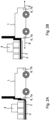
Figur 1A , der die freie Abstellfläche zum Abstellen einer aufgenommenen Palette befährt und dabei sein Überwachungsfeld fortlaufend in der Größe anpasst; - Figur 2A:
- ein Ausführungsbeispiel des erfindungsgemäßen autonom fahrenden Staplers, wobei die Hinderniserkennungseinrichtung eine erste Sensoreinheit und eine zweite Sensoreinheit umfasst;
- Figur 2B:
- ein Ausführungsbeispiel des erfindungsgemäßen autonom fahrenden Staplers, wobei die erste Sensoreinheit ein Überwachungsfeld erzeugt, welches unter der aufgenommenen Palette ausgesendet wird;
- Figur 2C:
- ein Ausführungsbeispiel des erfindungsgemäßen autonom fahrenden Staplers, wobei die erste Sensoreinheit in bzw. an einer Gabelspitze angeordnet ist; und
- Figur 3:
- ein Verfahren zum Betrieb des autonom fahrenden Staplers.
-
Figur 1A zeigt ein Ausführungsbeispiel eines erfindungsgemäßen autonom fahrenden Transportsystems, hier in Form eines Staplers 1. Der Stapler 1 dient vorzugsweise zum Transport von Paletten 2 und/oder Gitterboxen. Um die Paletten 2 und/oder Gitterboxen aufzunehmen umfasst der Stapler 1 vorzugsweise zwei Gabeln 3. Auf den Paletten 2 sind in diesem Fall verschiedene Güter 4 angeordnet. InFigur 1A sind die Paletten 2 in zwei Spalten angeordnet. Eine erste Spalte umfasst drei Paletten 2 und eine zweite Spalte umfasst zwei Paletten 2. In der zweiten Spalte ist daher eine freie Abstellfläche 5 vorhanden. Diese freie Abstellfläche 5 ist von drei Seiten durch andere Paletten 2 begrenzt. Wird die freie Abstellfläche 5 nun zum Abstellen einer weiteren Palette 2 verwendet, so gibt es beim Einfahren dieser weiteren Palette 2 kein Fluchtweg für eine etwaige Person, die sich auf der freien Abstellfläche 5 befindet, um beispielsweise Güter 4 auf einer der benachbarten Palette 2 zu sortieren. - Der Stapler 1 umfasst eine Antriebseinheit (nicht dargestellt). Vorzugsweise handelt es sich um eine elektrische Antriebseinheit, die beispielsweise induktiv (z.B. über zumindest eine Leiterbahn im Boden) oder über einen Akku mit elektrischer Energie versorgt wird. Der Stapler 1 umfasst außerdem eine Steuervorrichtung (nicht dargestellt), die eine Datenverarbeitungseinheit (nicht dargestellt) und eine Hinderniserkennungseinrichtung 6 aufweist. Die Hinderniserkennungseinrichtung 6 umfasst eine erste Sensoreinheit 7a und eine zweite Sensoreinheit 7b (siehe Figuren 2A, 2B, 2C). Die erste Sensoreinheit 7a ist rückseitig am Stapler 1, also dort, wo die Gabeln 3 befestigt sind, angeordnet. Die zweite Sensoreinheit 7b ist frontseitig am Stapler 1 angeordnet. Der Stapler 1 ist dazu ausgebildet, um sich nach einer aufgenommenen Palette 2 und/oder Gitterbox mit der Frontseite in Fahrtrichtung zum Ziel zu bewegen. Dies hat den Vorteil, dass die Palette 2 und/oder die Gitterbox die zweite Sensoreinheit 7b der Hinderniserkennungseinrichtung 6, die Hindernisse vor dem Stapler 1 erfasst, nicht verdeckt.
- Die erste Sensoreinheit 7a und/oder die zweite Sensoreinheit 7b umfasst zumindest einen optischen Sensor, zumindest einen akustischen Sensor oder zumindest einen elektromagnetischen Sensor. Es wäre denkbar, dass die erste Sensoreinheit 7a und die zweite Sensoreinheit 7b verschiedene Arten von Sensoren umfassen. Es wäre auch denkbar, dass die erste Sensoreinheit 7a und die zweite Sensoreinheit 7b eine unterschiedliche Anzahl von Sensoren umfassen.
- Der optische Sensor ist bevorzugt ein ToF-Sensor und/oder ein Laserscanner. Über Lichtlaufzeiten zwischen einem ausgesendeten Lichtimpuls und einem empfangenen Lichtimpuls, der an einem Hindernis reflektiert wurde, können Hindernisse in der Umgebung des Staplers 1 ermittelt werden.
- Die erste Sensoreinheit 7a ist dazu ausgebildet, um ein Überwachungsfeld 8 zu erzeugen. Die zweite Sensoreinheit 7b ist ebenfalls dazu ausgebildet, um ein Überwachungsfeld 8 zu erzeugen. Die Überwachungsfelder 8 der ersten Sensoreinheit 7a und der zweiten Sensoreinheit 7b können gleich groß oder verschieden groß sein.
- In
Figur 1A ist die erste Sensoreinheit 7a dazu ausgebildet, um mit ihrem Überwachungsfeld 8 die freie Abstellfläche 5 für die abzustellende Palette 2 und/oder Gitterbox zwischen anderen Paletten 2 auf Hindernisse hin zu untersuchen. Das Überwachungsfeld 8 ist in diesem Fall schraffiert dargestellt. Die Form des Überwachungsfeldes 8 ist nur beispielhaft gewählt und soll lediglich verdeutlichen, dass das Überwachungsfeld 8 auf die freie Abstellfläche 5 gerichtet ist. Das Überwachungsfeld 8 erstreckt sich vorzugsweise in Bodennähe. Dies bedeutet, dass ein Abstand zwischen dem Boden und dem Überwachungsfeld 8 vorzugsweise kleiner ist als 80 cm, 50 cm, 40 cm oder kleiner ist als 20 cm. Vorzugsweise verläuft das Überwachungsfeld 8 in etwa parallel zum Boden. Der Wortlaut "in etwa" beinhaltet vorzugsweise auch Abweichungen von weniger als 10° oder weniger als 5°. Es wäre auch denkbar, dass das Überwachungsfeld 8 unter einem Winkel auf den Boden der freien Abstellfläche 5 trifft. - Die Steuervorrichtung des Staplers 1 ist dazu ausgebildet, um die Antriebseinheit derart anzusteuern, dass der Stapler 1 bei einem fehlenden Hindernis einen Abstellbetriebsmodus einnimmt. Im Abstellbetriebsmodus fährt der Stapler 1 die Palette 2 und/oder die Gitterbox zum Abstellen in die freie Abstellfläche 5. Im Abstellbetriebsmodus ist die Hinderniserkennungseinrichtung 6 dazu ausgebildet, um während des Befahrens der freien Abstellfläche 5, zumindest bis zum Abstellen der Palette 2 und/oder der Gitterbox auf der freien Abstellfläche 5, das Überwachungsfeld 8 zu deaktivieren. Dies kann beispielsweise dadurch erfolgen, dass die Energieversorgung zur ersten Sensoreinheit 7a unterbrochen bzw. ein entsprechendes Steuersignal an die erste Sensoreinheit 7a angelegt wird. Dieser Sachverhalt ist in
Figur 1B dargestellt. - In einem alternativen nicht zur beanspruchten Erfindung gehörendem Beispiel ist die Hinderniserkennungseinrichtung 6 dazu ausgebildet, um während des Befahrens der freien Abstellfläche 5, zumindest bis zum Abstellen der Palette 2 und/oder der Gitterbox auf der freien Abstellfläche 5, das Überwachungsfeld 8 auf die frei Abstellfläche 5 zu begrenzen. Dieser Sachverhalt ist in
Figur 1C dargestellt. In diesem Fall ist die Datenverarbeitungseinheit dazu ausgebildet, um die erste Sensoreinheit 7a derart anzusteuern, dass diese ihr Überwachungsfeld 8 auf den noch nicht befahrenen Teil der freien Abstellfläche 5 begrenzt. Der Stapler 1 umfasst hierzu vorzugsweise eine Gebereinheit. Die Gebereinheit ist dazu ausgebildet, um im Abstellbetriebsmodus fortlaufend eine gefahrene Strecke zu ermitteln, wobei die Hinderniserkennungseinrichtung 6 dazu ausgebildet ist, um anhand der ermittelten Strecke das Überwachungsfeld 8 (der ersten Sensoreinheit 7a) fortlaufend zu begrenzen, also zu verkleinern. Das "Begrenzen" erfolgt dahingehend, dass benachbarte Paletten 2 und/oder Gitterboxen kein Hinderniserkennungssignal erzeugen. Die Gebereinheit ist vorzugsweise als Drehgeber ausgebildet und an einer Antriebswelle der Antriebseinheit angeordnet. Die Hinderniserkennungseinrichtung 6 ist dazu ausgebildet, um das Überwachungsfeld 8 (der ersten Sensoreinheit 7a) durch Verstellen des Abstrahlwinkels der ersten Sensoreinheit 7a zu begrenzen. Dies könnte beispielsweise durch ein Verkippen der ersten Sensoreinheit 7a oder durch Drehen eines Spiegels innerhalb der ersten Sensoreinheit 7a erfolgen. Je weiter der Stapler 1 in die freie Abstellfläche 5 fährt, desto größer könnte der Winkel zwischen dem Überwachungsfeld 8 und dem Boden sein. Das Begrenzen könnte auch dadurch erfolgen, dass die Hinderniserkennungseinrichtung 6 oder die Datenverarbeitungseinheit dazu ausgebildet ist, um das Überwachungsfeld 8 durch Ausblenden von bestimmten Bereichen, die über die freie Abstellfläche 5 hinausgehen, zu begrenzen. Dies könnte durch Ignorieren von reflektierten Lichtimpulsen erfolgen, die nach einer bestimmten Zeit eintreffen. In diesem Fall könnten Lichtimpulse, die benachbarte Paletten 2 und/oder Gitterboxen reflektieren, ignoriert werden. - Grundsätzlich wäre es auch denkbar, dass die Hinderniserkennungseinrichtung 6 dazu ausgebildet ist, um während des Befahrens der freien Abstellfläche 5, zumindest bis zum Abstellen der aufgenommenen Palette 2 und/oder der aufgenommenen Gitterbox auf der freien Abstellfläche 5, kein Hinderniserkennungssignal auszugeben.
- Es wäre auch denkbar, dass die Datenverarbeitungseinheit dazu ausgebildet ist, um während des Befahrens der freien Abstellfläche 5, zumindest bis zum Abstellen der Palette 2 und/oder der Gitterbox auf der freien Abstellfläche 5, ein Hinderniserkennungssignal der Hinderniserkennungseinrichtung 6 zu ignorieren. Vorzugsweise ist die Hinderniserkennungseinrichtung 6 mit der Datenverarbeitungseinheit verbunden. Dies kann über eine elektrische oder eine optische Verbindung erfolgen. Auch eine drahtlose Verbindung wäre denkbar. Die Datenverarbeitungseinheit, welche Teil der Steuervorrichtung ist, ist bevorzugt dazu ausgebildet, um der Hinderniserkennungseinrichtung 6 mitzuteilen, dass diese das Überwachungsfeld 8 der ersten Sensoreinheit 7a entsprechend deaktivieren bzw. dass diese kein Hinderniserkennungssignal ausgeben soll. Die Datenverarbeitungseinheit könnte ein solches Hinderniserkennungssignal im Abstellbetriebsmodus auch einfach ignorieren.
- Vorzugsweise ist die Datenverarbeitungseinheit dazu ausgebildet, um die Hinderniserkennungseinrichtung 6 derart anzusteuern, dass entweder die erste Sensoreinheit 7a oder die zweite Sensoreinheit 7b aktiviert ist (ein Überwachungsfeld 8 erzeugt), welche in Fahrtrichtung vorne am Stapler 1 angeordnet ist. Fährt der Stapler 1 vorwärts, so ist die zweite Sensoreinheit 7b aktiviert. Fährt der Stapler 1 rückwärts, so ist die erste Sensoreinheit 7a aktiviert. Die jeweils andere Sensoreinheit 7a bzw. 7b ist dann bevorzugt deaktiviert bzw. entsprechende Hinderniserkennungssignale führen zu keiner Auslösereaktion.
- In den
Figuren 2A, 2B ,2C ist dargestellt, wo die erste Sensoreinheit 7a und die zweite Sensoreinheit 7b am Stapler 1 angebracht sein können. In denFiguren 2A, 2B ist die erste Sensoreinheit 7a an einem unteren Bereich des Staplers 1 angeordnet. Die Steuervorrichtung ist dazu ausgebildet, um die Aufnahmevorrichtung derart anzusteuern, dass diese die aufgenommene Palette 2 und/oder die aufgenommene Gitterbox anhebt, sodass sich das Überwachungsfeld 8 der ersten Sensoreinheit 7a unterhalb der aufgenommenen Palette 2 und/oder unterhalb der aufgenommenen Gitterbox hindurch in Richtung der freien Abstellfläche 5 erstreckt. Dadurch wird zuverlässig vermieden, dass mit Gütern 4 beladene Paletten 2 bzw. Gitterboxen das Überwachungsfeld 8 verdecken. Die erste Sensoreinheit 7a könnte zusätzlich vom Unterboden des Staplers 1 in Richtung des Bodens (Fahrbahn) beabstandet angeordnet sein, sodass die Aufnahmevorrichtung die aufgenommene Palette und/oder die aufgenommene Gitterbox nur minimal (vorzugsweise weniger als 50 cm, 40 cm, 30 cm oder weniger als 20 cm) anheben muss. - Das Überwachungsfeld 8 der zweiten Sensoreinheit 7b wird dagegen nicht von einer Aufnahmevorrichtung und der durch die Aufnahmevorrichtung aufgenommenen Palette 2 und/oder Gitterbox verdeckt. Grundsätzlich wäre es denkbar, dass die erste Sensoreinheit 7a näher in Richtung des Bodens angeordnet ist als die zweite Sensoreinheit 7b.
- In
Figur 2C ist dargestellt, dass die erste Sensoreinheit 6a an einem Ende zumindest einer Gabel 3 angeordnet ist. Auch durch diese Maßnahme ist sichergestellt, dass das Überwachungsfeld 8 nicht durch die aufgenommene Palette 2 und/oder die aufgenommene Gitterbox verdeckt wird. -
Figur 3 beschreibt ein Verfahren zum Betrieb des autonom fahrenden Staplers 1. In einem ersten Verfahrensschritt S1 wird ein Überwachungsfeld 8 durch die erste Sensoreinheit 7a erzeugt, um mit diesem Überwachungsfeld 8 die freie Abstellfläche 5 für die abzustellende Palette 2 und/oder die abzustellende Gitterbox zwischen anderen Paletten 2 und/oder Gitterboxen auf Hindernisse hin zu untersuchen. - Im zweiten Verfahrensschritt S2 wird die Antriebseinheit durch die Steuervorrichtung derart angesteuert, dass der Stapler 1, bei einem fehlenden (nicht detektierten) Hindernis, einen Abstellbetriebsmodus einnimmt und die aufgenommene Palette 2 und/oder die aufgenommene Gitterbox zum Abstellen in die freie Abstellfläche 5 fährt.
- Im dritten Verfahrensschritt S3 wird das Überwachungsfeld 8 der ersten Sensoreinheit 7a deaktiviert. Alternativ dazu wird unterbunden, dass durch die erste Sensoreinheit 7a oder die Hinderniserkennungseinrichtung 6 ein Hinderniserkennungssignal ausgegeben wird bzw. ein ausgegebenes Hinderniserkennungssignal wird (insbesondere durch die Datenverarbeitungseinheit) ignoriert. Der dritte Verfahrensschritt S3 wird insbesondere so lange ausgeführt, solange sich der Stapler im Abstellbetriebsmodus befindet. Hat der Stapler 1 die aufgenommene Palette 2 und/oder die aufgenommene Gitterbox abgesetzt, so fährt er aus der freien Abstellfläche 5 heraus. In diesem Fall ist zumindest die zweite Sensoreinheit 7b aktiviert. Ergänzend kann auch die erste Sensoreinheit 7a wieder aktiviert werden bzw. entsprechende Hinderniserkennungssignale der ersten Sensoreinheit 7a führen wieder zu einer Auslösereaktion.
- Im zweiten und dritten Verfahrensschritt S2, S3 überwacht die Steuervorrichtung anhand eines Signals der Gebereinheit und/oder eines anderweitigen Positionssignals, dass die maximal gefahrene Distanz kleiner oder gleich der Tiefe der zuvor freigemessenen Fläche ist, d.h. der Stapler 1 nicht über die freigemessene Fläche (d.h. die freie Abstellfläche 5) hinausfährt.
- Grundsätzlich wäre es denkbar, dass die Datenverarbeitungseinheit ein Teil der Steuervorrichtung und/oder ein Teil der Hinderniserkennungseinrichtung 6 ist.
- Erfindung ist nicht auf die beschriebenen Ausführungsbeispiele beschränkt. Im Rahmen der Erfindung sind alle beschriebenen und/oder gezeichneten Merkmale beliebig miteinander kombinierbar.
Bezugszeichenliste Autonom fahrender Stapler 1 Palette 2 Gabeln 3 Güter 4 Freie Abstellfläche 5 Hinderniserkennungseinrichtung 6 Erste Sensoreinheit 7a Zweite Sensoreinheit 7b Überwachungsfeld 8 Verfahrensschritte S1, S2, S3
Claims (10)
- Autonom fahrendes Transportsystem (1) zum Transport von Paletten (2) und/oder Gitterboxen, wobei das Transportsystem (1) eine Aufnahmevorrichtung zur Aufnahme der Palette (2) und/oder Gitterbox umfasst,wobei das Transportsystem (1) eine Antriebseinheit und eine Steuervorrichtung umfasst, wobei die Steuervorrichtung eine Datenverarbeitungseinheit und eine Hinderniserkennungseinrichtung (6) mit einer ersten Sensoreinheit (7a) umfasst,wobei die erste Sensoreinheit (7a) dazu ausgebildet ist, um ein Überwachungsfeld (8) zu erzeugen, um eine freie Abstellfläche (5) für die Palette (2) und/oder Gitterbox zwischen anderen Paletten (2) und/oder Gitterboxen auf Hindernisse hin zu untersuchen,wobei die Steuervorrichtung dazu ausgebildet ist, um die Antriebseinheit derart anzusteuern, dass das Transportsystem (1), bei einem fehlenden Hindernis, einen Abstellbetriebsmodus einnimmt und die Palette (2) und/oder Gitterbox zum Abstellen in die freie Abstellfläche (5) fährt,dadurch gekennzeichnet, dassin dem Abstellbetriebsmodus:a) die Hinderniserkennungseinrichtung (6) dazu ausgebildet ist, um während des Befahrens der freien Abstellfläche (5), zumindest bis zum Abstellen der Palette (2) und/oder Gitterbox auf der freien Abstellfläche (5), das Überwachungsfeld (8) zu deaktivieren oder kein Hinderniserkennungssignal auszugeben; oderb) die Datenverarbeitungseinheit dazu ausgebildet ist, um während des Befahrens der freien Abstellfläche (5), zumindest bis zum Abstellen der Palette (2) und/oder Gitterbox auf der freien Abstellfläche (5), ein Hinderniserkennungssignal der Hinderniserkennungseinrichtung (6) zu ignorieren.
- Autonom fahrendes Transportsystem (1) nach Anspruch 1,
wobei die Steuervorrichtung dazu ausgebildet ist, um die Antriebseinheit derart anzusteuern, dass das Transportsystem (1) im Abstellbetriebsmodus nur auf dem freigemessenen Bereich der Abstellfläche (5) fährt. - Autonom fahrendes Transportsystem (1) nach einem der vorstehenden Ansprüche,
wobei die erste Sensoreinheit (7a) einen optischen Sensor, einen akustischen Sensor oder einen elektromagnetischen Sensor umfasst. - Autonom fahrendes Transportsystem (1) nach Anspruch 3,
wobei der optische Sensor ein ToF-Sensor und/oder ein Laserscanner ist. - Autonom fahrendes Transportsystem (1) nach einem der vorstehenden Ansprüche,
wobei die Aufnahmevorrichtung Gabeln (3) umfasst und wobei die erste Sensoreinheit (7a) an einem Ende zumindest einer Gabel (3) angeordnet ist. - Autonom fahrendes Transportsystem (1) nach einem der Ansprüche 1 bis 4,
wobei die erste Sensoreinheit (7a) an einem unteren Bereich des Transportsystems (1) angeordnet ist, wobei die Steuervorrichtung dazu ausgebildet ist, um die Aufnahmevorrichtung derart anzusteuern, dass diese die Palette (2) und/oder Gitterbox anhebt, sodass sich das Überwachungsfeld (8) der ersten Sensoreinheit (7a) unterhalb der Palette (2) und/oder Gitterbox hindurch in Richtung der freien Abstellfläche (5) erstreckt, um diese auf Hindernisse hin zu untersuchen. - Autonom fahrendes Transportsystem (1) nach einem der vorstehenden Ansprüche,
wobei die Hinderniserkennungseinrichtung (6) eine zweite Sensoreinheit (7b) umfasst, wobei die erste Sensoreinheit (7a) rückseitig am Transportsystem (1) und die zweite Sensoreinheit (7b) frontseitig am Transportsystem (1) angeordnet ist. - Autonom fahrendes Transportsystem (1) nach Anspruch 7,
wobei die Steuervorrichtung dazu ausgebildet, um die Geschwindigkeit, mit welcher das Transportsystem (1) die freie Abstellfläche (5) befährt, gegenüber einer Geschwindigkeit, mit welcher das Transportsystem (5) bewegt wird, wenn die zweite Sensoreinheit (7b) in Bewegungsrichtung des Transportsystems (1) vorne angeordnet ist, zu reduzieren. - Autonom fahrendes Transportsystem (1) nach einem der vorstehenden Ansprüche,
wobei die Antriebseinheit eine elektrische Antriebseinheit ist und wobei die Steuervorrichtung im Abstellbetriebsmodus dazu ausgebildet ist, um die Stromaufnahme der Antriebseinheit zu überwachen, wobei für den Fall, dass die Stromaufnahme der Antriebseinheit einen Schwellwert überschreitet die Steuervorrichtung die Antriebseinheit derart ansteuert, dass diese das Transportsystem (1) stoppt oder aus der freien Abstellfläche (5) herausfährt. - Verfahren zum Betrieb eines autonom fahrenden Transportsystems (1) zum Transport von Paletten (2) und/oder Gitterboxen, mit den folgenden Verfahrensschritten:- Erzeugen eines Überwachungsfeldes (8), um eine freie Abstellfläche (5) für eine abzustellende Palette (2) und/oder Gitterbox zwischen anderen Paletten (2) und/oder Gitterboxen auf Hindernisse hin zu untersuchen,- Ansteuern einer Antriebseinheit, so dass das Transportsystem (1), bei einem fehlenden Hindernis, einen Abstellbetriebsmodus einnimmt und die Palette (2) und/oder Gitterbox zum Abstellen in die freie Abstellfläche (5) fährt;- Deaktivieren des Überwachungsfeldes (8) oder Unterbinden, dass ein Hinderniserkennungssignal ausgegeben wird oder Ignorieren eines Hinderniserkennungssignals solange sich das Transportsystem (1) im Abstellbetriebsmodus befindet.
Applications Claiming Priority (1)
| Application Number | Priority Date | Filing Date | Title |
|---|---|---|---|
| DE102022115797.0A DE102022115797A1 (de) | 2022-06-24 | 2022-06-24 | Autonom fahrendes Transportsystem zum Transport von Paletten und/oder Gitterboxen und Verfahren zum Betrieb eines solchen autonom fahrenden Transportsystems |
Publications (2)
| Publication Number | Publication Date |
|---|---|
| EP4296215A1 EP4296215A1 (de) | 2023-12-27 |
| EP4296215B1 true EP4296215B1 (de) | 2025-03-12 |
Family
ID=86861708
Family Applications (1)
| Application Number | Title | Priority Date | Filing Date |
|---|---|---|---|
| EP23179772.1A Active EP4296215B1 (de) | 2022-06-24 | 2023-06-16 | Autonom fahrendes transportsystem zum transport von paletten und/oder gitterboxen und verfahren zum betrieb eines solchen autonom fahrenden transportsystems |
Country Status (4)
| Country | Link |
|---|---|
| US (1) | US20230416063A1 (de) |
| EP (1) | EP4296215B1 (de) |
| CN (1) | CN117284970A (de) |
| DE (1) | DE102022115797A1 (de) |
Families Citing this family (3)
| Publication number | Priority date | Publication date | Assignee | Title |
|---|---|---|---|---|
| AU2023241271A1 (en) * | 2022-10-04 | 2024-04-18 | The Raymond Corporation | Obstacle detection functionality for material handling vehicles based on location |
| EP4671188A1 (de) * | 2024-06-27 | 2025-12-31 | Jungheinrich AG | Fahrerloses flurförderzeug mit einer erkennungseinrichtung sowie verfahren zum betrieb eines fahrerlosen flurförderzeugs |
| DE102024134116A1 (de) * | 2024-11-20 | 2026-05-21 | Jungheinrich Aktiengesellschaft | Fahrerloses Flurförderzeug mit mindestens einem Schutzfeld sowie ein Verfahren zur Steuerung eines fahrerlosen Flurförderzeugs |
Citations (1)
| Publication number | Priority date | Publication date | Assignee | Title |
|---|---|---|---|---|
| US20200101971A1 (en) * | 2018-09-28 | 2020-04-02 | Logistics and Supply Chain MultiTech R&D Centre Limited | An automated guide vehicle with a collision avoidance apparatus |
Family Cites Families (22)
| Publication number | Priority date | Publication date | Assignee | Title |
|---|---|---|---|---|
| IT1269440B (it) * | 1994-01-19 | 1997-04-01 | Fita Om Carrelli Elevatori S P | Carrello elevatore a motorizzazione elettrica |
| JP3053348B2 (ja) * | 1995-02-16 | 2000-06-19 | 株式会社豊田自動織機製作所 | パレット段積み装置 |
| EP1494954A4 (de) * | 2002-02-12 | 2008-04-30 | Tynecat Technologies Pty Ltd | Lenkbarer transportwagen |
| US8210791B2 (en) * | 2004-05-03 | 2012-07-03 | Jervis B. Webb Company | Automatic transport loading system and method |
| US7236851B2 (en) * | 2005-06-17 | 2007-06-26 | Epc4Roi Limited Partnership | Self-contained RF identification apparatus for pallet conveyances |
| EP2302416B1 (de) * | 2009-09-28 | 2013-06-19 | Sick Ag | Sicherheitsscanner |
| ATE545045T1 (de) * | 2009-12-17 | 2012-02-15 | Sick Ag | Optoelektronischer sensor |
| JP5312367B2 (ja) * | 2010-02-12 | 2013-10-09 | 村田機械株式会社 | 走行台車システム |
| US9187244B2 (en) * | 2010-12-15 | 2015-11-17 | Symbotic, LLC | BOT payload alignment and sensing |
| US8965561B2 (en) * | 2013-03-15 | 2015-02-24 | Cybernet Systems Corporation | Automated warehousing using robotic forklifts |
| US20170015537A1 (en) * | 2015-07-13 | 2017-01-19 | George R. Bosworth, III | Lifting fork positioning system |
| US10346797B2 (en) * | 2016-09-26 | 2019-07-09 | Cybernet Systems, Inc. | Path and load localization and operations supporting automated warehousing using robotic forklifts or other material handling vehicles |
| JP2019148881A (ja) * | 2018-02-26 | 2019-09-05 | 日本電産シンポ株式会社 | 移動体、移動体を制御する方法およびコンピュータプログラム |
| US11305936B2 (en) * | 2018-09-28 | 2022-04-19 | Autoguide, LLC | Commercial logistic facility, configurable modular robotic autonomous guided vehicle, and method therefor |
| US11142413B2 (en) * | 2019-01-28 | 2021-10-12 | Assa Abloy Entrance Systems Ab | Systems and methods for automated loading and unloading at a dock station |
| EP3950566B1 (de) * | 2019-04-02 | 2024-03-20 | Beijing Geekplus Technology Co., Ltd. | Roboter mit hoher position, verfahren zur kalibrierung der rückkehr eines speicherbehälters und speichermedium |
| JP7156174B2 (ja) * | 2019-05-27 | 2022-10-19 | 株式会社豊田自動織機 | フォークリフトの荷役制御装置 |
| DE102019215180A1 (de) * | 2019-10-02 | 2021-04-08 | Robert Bosch Gmbh | Flurförderzeug, eingerichtet für den fahrerlosen, autonom agierenden Betrieb für eine zu transportierende Last |
| DE102020006337A1 (de) * | 2019-10-09 | 2021-04-15 | Metralabs Gmbh Neue Technologien Und Systeme | Autonomes Flurförderzeug |
| DE102020102513B4 (de) * | 2020-01-31 | 2022-07-07 | Eisenmann Gmbh | Transportsystem zum Transportieren von Werkstücken und Verfahren zum Betreiben eines solchen Transportsystems |
| CN113703460B (zh) * | 2021-08-31 | 2024-02-09 | 上海木蚁机器人科技有限公司 | 导航车识别空位的方法、装置及系统 |
| US20250128925A1 (en) * | 2023-10-18 | 2025-04-24 | Gideon Brothers d.o.o. | Autonomous mobile robot operations for last rows in-trailer loading |
-
2022
- 2022-06-24 DE DE102022115797.0A patent/DE102022115797A1/de active Pending
-
2023
- 2023-06-16 EP EP23179772.1A patent/EP4296215B1/de active Active
- 2023-06-23 US US18/213,372 patent/US20230416063A1/en active Pending
- 2023-06-26 CN CN202310757930.0A patent/CN117284970A/zh active Pending
Patent Citations (1)
| Publication number | Priority date | Publication date | Assignee | Title |
|---|---|---|---|---|
| US20200101971A1 (en) * | 2018-09-28 | 2020-04-02 | Logistics and Supply Chain MultiTech R&D Centre Limited | An automated guide vehicle with a collision avoidance apparatus |
Also Published As
| Publication number | Publication date |
|---|---|
| CN117284970A (zh) | 2023-12-26 |
| DE102022115797A1 (de) | 2024-01-04 |
| US20230416063A1 (en) | 2023-12-28 |
| EP4296215A1 (de) | 2023-12-27 |
Similar Documents
| Publication | Publication Date | Title |
|---|---|---|
| EP3583586B1 (de) | Automatisch geführtes transportfahrzeug für container und verfahren zum betreiben desselben sowie system mit einem automatisch geführten transportfahrzeug | |
| EP4296215A1 (de) | Autonom fahrendes transportsystem zum transport von paletten und/oder gitterboxen und verfahren zum betrieb eines solchen autonom fahrenden transportsystems | |
| EP2851331B1 (de) | Verfahren zur Steuerung eines Kommissionierflurförderzeugs | |
| EP3241801B1 (de) | Verfahren zur kollisionsüberwachung bei einem flurförderzeug | |
| EP2151402B1 (de) | Logistiksystem | |
| EP3800158B1 (de) | Flurförderzeug, eingerichtet für den fahrerlosen, autonom agierenden betrieb für eine zu transportierende last | |
| AT522418B1 (de) | Fertigungsvorrichtung und Fördermittel | |
| EP2339376A1 (de) | Optoelektronischer Sensor | |
| EP3118152B1 (de) | Verfahren zur geschwindigkeitssteuerung eines kommissionierflurförderzeugs | |
| EP4136049B1 (de) | Flurförderzeug mit lastaufnahmemitteln zur aufnahme von langgut | |
| DE102016120117A1 (de) | Flurförderzeug mit einer Sensoreinrichtung zur Überwachung eines Umgebungsbereiches | |
| DE102020100166B4 (de) | Verfahren zum automatischen Einparken eines Kraftfahrzeugs in eine durch ein überfahrbares Hindernis begrenzte Querparklücke, Parkassistenzsystem und Kraftfahrzeug | |
| DE202020103181U1 (de) | Ein autonomer Gabelstapler | |
| DE202014102274U1 (de) | Folienerkennung und Palettentyperkennung mittels Kanalfahrzeug in einem Kanalregallager | |
| WO2017191271A1 (de) | System und verfahren zur bestimmung der position eines transportfahrzeugs sowie transportfahrzeug | |
| DE102020215149A1 (de) | Verfahren zum Betreiben eines Fahrzeugs in einem Regalgang in Abhängigkeit von einer Fahrweginformation | |
| EP4439218A1 (de) | Fahrerloses transportfahrzeug | |
| DE102015113445A1 (de) | Verfahren zur Geschwindigkeitssteuerung eines Kommissionierflurförderzeugs | |
| DE102004047209B4 (de) | Verfahren und Vorrichtung zur Sicherheitsüberwachung für Transportfahrzeuge | |
| DE202022103511U1 (de) | Autonom fahrendes Transportsystem zum Transport von Paletten und/oder Gitterboxen | |
| EP3450324A1 (de) | Verfahren zum steuern der bewegung eines flughafen-vorfeld-fahrzeuges sowie entsprechendes vorfeld-fahrzeug | |
| DE102019215176A1 (de) | Flurförderzeug, eingerichtet für den fahrerlosen, autonom agierenden Betrieb für eine zu transportierende Last | |
| EP1103494B1 (de) | Lagersystem für Paletten | |
| EP4067287A1 (de) | Verfahren zum betreiben eines flurförderzeugs in einem intralogistischen system und intralogistisches system | |
| DE102024119287A1 (de) | Frachthandhabungssteuervorrichtung |
Legal Events
| Date | Code | Title | Description |
|---|---|---|---|
| PUAI | Public reference made under article 153(3) epc to a published international application that has entered the european phase |
Free format text: ORIGINAL CODE: 0009012 |
|
| STAA | Information on the status of an ep patent application or granted ep patent |
Free format text: STATUS: THE APPLICATION HAS BEEN PUBLISHED |
|
| AK | Designated contracting states |
Kind code of ref document: A1 Designated state(s): AL AT BE BG CH CY CZ DE DK EE ES FI FR GB GR HR HU IE IS IT LI LT LU LV MC ME MK MT NL NO PL PT RO RS SE SI SK SM TR |
|
| STAA | Information on the status of an ep patent application or granted ep patent |
Free format text: STATUS: REQUEST FOR EXAMINATION WAS MADE |
|
| 17P | Request for examination filed |
Effective date: 20240109 |
|
| RBV | Designated contracting states (corrected) |
Designated state(s): AL AT BE BG CH CY CZ DE DK EE ES FI FR GB GR HR HU IE IS IT LI LT LU LV MC ME MK MT NL NO PL PT RO RS SE SI SK SM TR |
|
| STAA | Information on the status of an ep patent application or granted ep patent |
Free format text: STATUS: EXAMINATION IS IN PROGRESS |
|
| 17Q | First examination report despatched |
Effective date: 20240405 |
|
| GRAP | Despatch of communication of intention to grant a patent |
Free format text: ORIGINAL CODE: EPIDOSNIGR1 |
|
| STAA | Information on the status of an ep patent application or granted ep patent |
Free format text: STATUS: GRANT OF PATENT IS INTENDED |
|
| RIC1 | Information provided on ipc code assigned before grant |
Ipc: G05D 109/10 20240101ALI20240930BHEP Ipc: G05D 107/70 20240101ALI20240930BHEP Ipc: G05D 105/28 20240101ALI20240930BHEP Ipc: G05D 1/667 20240101ALI20240930BHEP Ipc: G05D 1/242 20240101ALI20240930BHEP Ipc: G05D 1/43 20240101ALI20240930BHEP Ipc: G01S 17/931 20200101ALI20240930BHEP Ipc: B66F 17/00 20060101ALI20240930BHEP Ipc: B66F 9/075 20060101ALI20240930BHEP Ipc: B66F 9/06 20060101AFI20240930BHEP |
|
| INTG | Intention to grant announced |
Effective date: 20241022 |
|
| GRAS | Grant fee paid |
Free format text: ORIGINAL CODE: EPIDOSNIGR3 |
|
| GRAA | (expected) grant |
Free format text: ORIGINAL CODE: 0009210 |
|
| STAA | Information on the status of an ep patent application or granted ep patent |
Free format text: STATUS: THE PATENT HAS BEEN GRANTED |
|
| AK | Designated contracting states |
Kind code of ref document: B1 Designated state(s): AL AT BE BG CH CY CZ DE DK EE ES FI FR GB GR HR HU IE IS IT LI LT LU LV MC ME MK MT NL NO PL PT RO RS SE SI SK SM TR |
|
| REG | Reference to a national code |
Ref country code: GB Ref legal event code: FG4D Free format text: NOT ENGLISH |
|
| REG | Reference to a national code |
Ref country code: CH Ref legal event code: EP |
|
| REG | Reference to a national code |
Ref country code: DE Ref legal event code: R096 Ref document number: 502023000676 Country of ref document: DE |
|
| REG | Reference to a national code |
Ref country code: IE Ref legal event code: FG4D Free format text: LANGUAGE OF EP DOCUMENT: GERMAN |
|
| PG25 | Lapsed in a contracting state [announced via postgrant information from national office to epo] |
Ref country code: RS Free format text: LAPSE BECAUSE OF FAILURE TO SUBMIT A TRANSLATION OF THE DESCRIPTION OR TO PAY THE FEE WITHIN THE PRESCRIBED TIME-LIMIT Effective date: 20250612 |
|
| PG25 | Lapsed in a contracting state [announced via postgrant information from national office to epo] |
Ref country code: FI Free format text: LAPSE BECAUSE OF FAILURE TO SUBMIT A TRANSLATION OF THE DESCRIPTION OR TO PAY THE FEE WITHIN THE PRESCRIBED TIME-LIMIT Effective date: 20250312 |
|
| PGFP | Annual fee paid to national office [announced via postgrant information from national office to epo] |
Ref country code: DE Payment date: 20250618 Year of fee payment: 3 |
|
| PG25 | Lapsed in a contracting state [announced via postgrant information from national office to epo] |
Ref country code: ES Free format text: LAPSE BECAUSE OF FAILURE TO SUBMIT A TRANSLATION OF THE DESCRIPTION OR TO PAY THE FEE WITHIN THE PRESCRIBED TIME-LIMIT Effective date: 20250312 |
|
| REG | Reference to a national code |
Ref country code: LT Ref legal event code: MG9D |
|
| PG25 | Lapsed in a contracting state [announced via postgrant information from national office to epo] |
Ref country code: NO Free format text: LAPSE BECAUSE OF FAILURE TO SUBMIT A TRANSLATION OF THE DESCRIPTION OR TO PAY THE FEE WITHIN THE PRESCRIBED TIME-LIMIT Effective date: 20250612 |
|
| PG25 | Lapsed in a contracting state [announced via postgrant information from national office to epo] |
Ref country code: HR Free format text: LAPSE BECAUSE OF FAILURE TO SUBMIT A TRANSLATION OF THE DESCRIPTION OR TO PAY THE FEE WITHIN THE PRESCRIBED TIME-LIMIT Effective date: 20250312 |
|
| REG | Reference to a national code |
Ref country code: NL Ref legal event code: MP Effective date: 20250312 |
|
| PG25 | Lapsed in a contracting state [announced via postgrant information from national office to epo] |
Ref country code: LV Free format text: LAPSE BECAUSE OF FAILURE TO SUBMIT A TRANSLATION OF THE DESCRIPTION OR TO PAY THE FEE WITHIN THE PRESCRIBED TIME-LIMIT Effective date: 20250312 |
|
| PG25 | Lapsed in a contracting state [announced via postgrant information from national office to epo] |
Ref country code: GR Free format text: LAPSE BECAUSE OF FAILURE TO SUBMIT A TRANSLATION OF THE DESCRIPTION OR TO PAY THE FEE WITHIN THE PRESCRIBED TIME-LIMIT Effective date: 20250613 Ref country code: BG Free format text: LAPSE BECAUSE OF FAILURE TO SUBMIT A TRANSLATION OF THE DESCRIPTION OR TO PAY THE FEE WITHIN THE PRESCRIBED TIME-LIMIT Effective date: 20250312 |
|
| PGFP | Annual fee paid to national office [announced via postgrant information from national office to epo] |
Ref country code: AT Payment date: 20250721 Year of fee payment: 3 |
|
| PG25 | Lapsed in a contracting state [announced via postgrant information from national office to epo] |
Ref country code: NL Free format text: LAPSE BECAUSE OF FAILURE TO SUBMIT A TRANSLATION OF THE DESCRIPTION OR TO PAY THE FEE WITHIN THE PRESCRIBED TIME-LIMIT Effective date: 20250312 |
|
| PG25 | Lapsed in a contracting state [announced via postgrant information from national office to epo] |
Ref country code: SE Free format text: LAPSE BECAUSE OF FAILURE TO SUBMIT A TRANSLATION OF THE DESCRIPTION OR TO PAY THE FEE WITHIN THE PRESCRIBED TIME-LIMIT Effective date: 20250312 |
|
| PG25 | Lapsed in a contracting state [announced via postgrant information from national office to epo] |
Ref country code: SM Free format text: LAPSE BECAUSE OF FAILURE TO SUBMIT A TRANSLATION OF THE DESCRIPTION OR TO PAY THE FEE WITHIN THE PRESCRIBED TIME-LIMIT Effective date: 20250312 |
|
| PG25 | Lapsed in a contracting state [announced via postgrant information from national office to epo] |
Ref country code: PT Free format text: LAPSE BECAUSE OF FAILURE TO SUBMIT A TRANSLATION OF THE DESCRIPTION OR TO PAY THE FEE WITHIN THE PRESCRIBED TIME-LIMIT Effective date: 20250714 |
|
| PG25 | Lapsed in a contracting state [announced via postgrant information from national office to epo] |
Ref country code: IT Free format text: LAPSE BECAUSE OF FAILURE TO SUBMIT A TRANSLATION OF THE DESCRIPTION OR TO PAY THE FEE WITHIN THE PRESCRIBED TIME-LIMIT Effective date: 20250312 Ref country code: PL Free format text: LAPSE BECAUSE OF FAILURE TO SUBMIT A TRANSLATION OF THE DESCRIPTION OR TO PAY THE FEE WITHIN THE PRESCRIBED TIME-LIMIT Effective date: 20250312 |
|
| PG25 | Lapsed in a contracting state [announced via postgrant information from national office to epo] |
Ref country code: CZ Free format text: LAPSE BECAUSE OF FAILURE TO SUBMIT A TRANSLATION OF THE DESCRIPTION OR TO PAY THE FEE WITHIN THE PRESCRIBED TIME-LIMIT Effective date: 20250312 Ref country code: EE Free format text: LAPSE BECAUSE OF FAILURE TO SUBMIT A TRANSLATION OF THE DESCRIPTION OR TO PAY THE FEE WITHIN THE PRESCRIBED TIME-LIMIT Effective date: 20250312 |
|
| PG25 | Lapsed in a contracting state [announced via postgrant information from national office to epo] |
Ref country code: RO Free format text: LAPSE BECAUSE OF FAILURE TO SUBMIT A TRANSLATION OF THE DESCRIPTION OR TO PAY THE FEE WITHIN THE PRESCRIBED TIME-LIMIT Effective date: 20250312 |
|
| PG25 | Lapsed in a contracting state [announced via postgrant information from national office to epo] |
Ref country code: SK Free format text: LAPSE BECAUSE OF FAILURE TO SUBMIT A TRANSLATION OF THE DESCRIPTION OR TO PAY THE FEE WITHIN THE PRESCRIBED TIME-LIMIT Effective date: 20250312 |
|
| PG25 | Lapsed in a contracting state [announced via postgrant information from national office to epo] |
Ref country code: IS Free format text: LAPSE BECAUSE OF FAILURE TO SUBMIT A TRANSLATION OF THE DESCRIPTION OR TO PAY THE FEE WITHIN THE PRESCRIBED TIME-LIMIT Effective date: 20250712 |
|
| REG | Reference to a national code |
Ref country code: DE Ref legal event code: R097 Ref document number: 502023000676 Country of ref document: DE |
|
| PG25 | Lapsed in a contracting state [announced via postgrant information from national office to epo] |
Ref country code: DK Free format text: LAPSE BECAUSE OF FAILURE TO SUBMIT A TRANSLATION OF THE DESCRIPTION OR TO PAY THE FEE WITHIN THE PRESCRIBED TIME-LIMIT Effective date: 20250312 |
|
| PLBE | No opposition filed within time limit |
Free format text: ORIGINAL CODE: 0009261 |
|
| STAA | Information on the status of an ep patent application or granted ep patent |
Free format text: STATUS: NO OPPOSITION FILED WITHIN TIME LIMIT |
|
| REG | Reference to a national code |
Ref country code: CH Ref legal event code: L10 Free format text: ST27 STATUS EVENT CODE: U-0-0-L10-L00 (AS PROVIDED BY THE NATIONAL OFFICE) Effective date: 20260121 |
|
| PG25 | Lapsed in a contracting state [announced via postgrant information from national office to epo] |
Ref country code: MC Free format text: LAPSE BECAUSE OF FAILURE TO SUBMIT A TRANSLATION OF THE DESCRIPTION OR TO PAY THE FEE WITHIN THE PRESCRIBED TIME-LIMIT Effective date: 20250312 |
|
| PG25 | Lapsed in a contracting state [announced via postgrant information from national office to epo] |
Ref country code: LU Free format text: LAPSE BECAUSE OF NON-PAYMENT OF DUE FEES Effective date: 20250616 |
|
| 26N | No opposition filed |
Effective date: 20251215 |
|
| REG | Reference to a national code |
Ref country code: BE Ref legal event code: MM Effective date: 20250630 |
|
| PG25 | Lapsed in a contracting state [announced via postgrant information from national office to epo] |
Ref country code: IE Free format text: LAPSE BECAUSE OF NON-PAYMENT OF DUE FEES Effective date: 20250616 |
|
| PG25 | Lapsed in a contracting state [announced via postgrant information from national office to epo] |
Ref country code: BE Free format text: LAPSE BECAUSE OF NON-PAYMENT OF DUE FEES Effective date: 20250630 |
|
| PG25 | Lapsed in a contracting state [announced via postgrant information from national office to epo] |
Ref country code: FR Free format text: LAPSE BECAUSE OF NON-PAYMENT OF DUE FEES Effective date: 20250630 |