EP4295672A1 - Support de plantes - Google Patents
Support de plantes Download PDFInfo
- Publication number
- EP4295672A1 EP4295672A1 EP22180540.1A EP22180540A EP4295672A1 EP 4295672 A1 EP4295672 A1 EP 4295672A1 EP 22180540 A EP22180540 A EP 22180540A EP 4295672 A1 EP4295672 A1 EP 4295672A1
- Authority
- EP
- European Patent Office
- Prior art keywords
- plant carrier
- drain
- inlet
- water
- plant
- Prior art date
- Legal status (The legal status is an assumption and is not a legal conclusion. Google has not performed a legal analysis and makes no representation as to the accuracy of the status listed.)
- Pending
Links
- 238000003973 irrigation Methods 0.000 claims abstract description 51
- 230000002262 irrigation Effects 0.000 claims abstract description 51
- 230000005484 gravity Effects 0.000 claims description 26
- 238000005192 partition Methods 0.000 claims description 3
- XLYOFNOQVPJJNP-UHFFFAOYSA-N water Substances O XLYOFNOQVPJJNP-UHFFFAOYSA-N 0.000 description 82
- 239000000969 carrier Substances 0.000 description 10
- 230000000694 effects Effects 0.000 description 4
- 238000000034 method Methods 0.000 description 4
- 230000008901 benefit Effects 0.000 description 2
- 235000015097 nutrients Nutrition 0.000 description 2
- 239000002245 particle Substances 0.000 description 2
- 230000000149 penetrating effect Effects 0.000 description 2
- 239000000758 substrate Substances 0.000 description 2
- 239000008400 supply water Substances 0.000 description 2
- QVGXLLKOCUKJST-UHFFFAOYSA-N atomic oxygen Chemical compound [O] QVGXLLKOCUKJST-UHFFFAOYSA-N 0.000 description 1
- 230000000903 blocking effect Effects 0.000 description 1
- 238000009313 farming Methods 0.000 description 1
- 239000012530 fluid Substances 0.000 description 1
- 239000007788 liquid Substances 0.000 description 1
- 229910052760 oxygen Inorganic materials 0.000 description 1
- 239000001301 oxygen Substances 0.000 description 1
- 125000006850 spacer group Chemical group 0.000 description 1
Images


Classifications
-
- A—HUMAN NECESSITIES
- A01—AGRICULTURE; FORESTRY; ANIMAL HUSBANDRY; HUNTING; TRAPPING; FISHING
- A01G—HORTICULTURE; CULTIVATION OF VEGETABLES, FLOWERS, RICE, FRUIT, VINES, HOPS OR SEAWEED; FORESTRY; WATERING
- A01G31/00—Soilless cultivation, e.g. hydroponics
- A01G31/02—Special apparatus therefor
-
- A—HUMAN NECESSITIES
- A01—AGRICULTURE; FORESTRY; ANIMAL HUSBANDRY; HUNTING; TRAPPING; FISHING
- A01G—HORTICULTURE; CULTIVATION OF VEGETABLES, FLOWERS, RICE, FRUIT, VINES, HOPS OR SEAWEED; FORESTRY; WATERING
- A01G9/00—Cultivation in receptacles, forcing-frames or greenhouses; Edging for beds, lawn or the like
- A01G9/02—Receptacles, e.g. flower-pots or boxes; Glasses for cultivating flowers
-
- A—HUMAN NECESSITIES
- A01—AGRICULTURE; FORESTRY; ANIMAL HUSBANDRY; HUNTING; TRAPPING; FISHING
- A01G—HORTICULTURE; CULTIVATION OF VEGETABLES, FLOWERS, RICE, FRUIT, VINES, HOPS OR SEAWEED; FORESTRY; WATERING
- A01G31/00—Soilless cultivation, e.g. hydroponics
- A01G31/02—Special apparatus therefor
- A01G31/06—Hydroponic culture on racks or in stacked containers
-
- A—HUMAN NECESSITIES
- A01—AGRICULTURE; FORESTRY; ANIMAL HUSBANDRY; HUNTING; TRAPPING; FISHING
- A01G—HORTICULTURE; CULTIVATION OF VEGETABLES, FLOWERS, RICE, FRUIT, VINES, HOPS OR SEAWEED; FORESTRY; WATERING
- A01G25/00—Watering gardens, fields, sports grounds or the like
-
- A—HUMAN NECESSITIES
- A01—AGRICULTURE; FORESTRY; ANIMAL HUSBANDRY; HUNTING; TRAPPING; FISHING
- A01G—HORTICULTURE; CULTIVATION OF VEGETABLES, FLOWERS, RICE, FRUIT, VINES, HOPS OR SEAWEED; FORESTRY; WATERING
- A01G9/00—Cultivation in receptacles, forcing-frames or greenhouses; Edging for beds, lawn or the like
- A01G9/02—Receptacles, e.g. flower-pots or boxes; Glasses for cultivating flowers
- A01G9/029—Receptacles for seedlings
Definitions
- the present invention relates to a plant carrier with a watering space, an inlet and an outlet, which has a drainage path arrangement.
- Such a plant carrier is used in particular in so-called “vertical farming", i.e. in a greenhouse arrangement in which several such plant carriers are arranged one above the other in the direction of gravity.
- vertical farming i.e. in a greenhouse arrangement in which several such plant carriers are arranged one above the other in the direction of gravity.
- a particularly preferred application here is the arrangement of the plant carriers in a block storage, in which the plant carriers are stacked directly on top of each other.
- seeds, seedlings or young plants are grown on a substrate or other support.
- the plants, or more precisely the roots of the plants need to be watered from time to time. It is often desirable for the roots of the plants to be wetted for a certain period of time, after which the water is allowed to drain away again so that the roots come into contact with oxygen.
- this intermittent irrigation requires a relatively high control effort, which requires, among other things, valves that are arranged in the area of the drain in order to drain the water from the irrigation room or to keep it there.
- the invention is based on the object of providing a plant support that is suitable for intermittent irrigation and has a simple structure. This object is achieved in a plant carrier of the type mentioned at the outset in that the drainage path arrangement has a first drainage path with a first flow direction and a second drainage path, the second drainage path having at least one mouth into the first drainage path and a second flow direction in the area of the mouth has a directional component that is opposite to the first flow direction in the area of the mouth.
- a valve is no longer required to control the water as it flows away.
- the outflowing water flows through the first drainage path on the one hand and through the second drainage path on the other hand.
- the water flowing through the second drain path then meets the water flowing through the first drain path and, since the water from the second flow path has a directional component that is opposite to the direction in which the water flows through the first drain path, this slows down Water flowing through the second drainage path affects the water in the first drainage path and thereby leads to a throttling of the flow of water that flows out of the irrigation room as a whole.
- the second drainage path has at least five openings in the first drainage path. This results in five points of failure in which the flow of water flowing out is disrupted and slowed down by the first drainage path. The more mouths there are, the greater the throttling effect.
- the first flow path has at least a first section and a second section which are connected in series, the first section and the second section being arranged next to one another.
- the draining water must therefore make a turn of approximately 180°, which results in further throttling and braking of the flow of water flowing through the drainage path arrangement.
- a second section of the second drainage path can also be connected in parallel to the second section of the first drainage path, so that openings of the second drainage path into the first drainage path also arise in the second section. This improves the throttling effect even further.
- the first drain path has an odd number of sections that are connected in series and arranged next to one another. This results in a meandering guidance of the first drainage path with a correspondingly large number of deflections of the water that flows through the drainage path arrangement.
- the "input" of the first flow path is then not at the same end as the "output”. Mouths of the second drain path can be present in all sections, with a flow in the first drain path meeting an oppositely directed flow in the second drain path at all mouths.
- the first drain has a drain opening which is connected to the drain path arrangement via an impact head device, the impact head device having an impact head directed upwards in the direction of gravity, the surface of which merges into a wall of a first channel, and the drain path arrangement via at least an opening of the impact head arrangement communicates with a second channel and the first channel and the second channel open into or run through the drain opening.
- the water that flows out of a plant support that is higher in the direction of gravity must flow through one or more plant supports that are arranged further down and, if you want to avoid that the outflowing water, which is in some respects used up, flows through the irrigation space of the plant carrier or plant carriers arranged further down, ensuring that the water draining from the upper plant carrier can flow away through the drain of a plant carrier arranged further down.
- the impact head is provided onto which the water draining from an upper plant support emerges. The water is then led from the impact head through a first channel into the drain opening.
- the water draining from the plant carrier, which is equipped with this impact head device then flows into the second channel.
- a mixing of the water from the upper and lower plant carrier then only takes place in the impact head device or even afterwards. This can prevent water draining from the upper plant support from penetrating into the irrigation space of the lower plant support.
- the impact head device is aligned with the drain opening along the direction of gravity. This has particular advantages if the plant supports are designed to be stackable. In this case, the impact head device is located below the drain opening in the direction of gravity plant support arranged above. You can also arrange more than two plant supports one above the other in the direction of gravity without the fall height being too great.
- the impact head device is connected to a pipe directed upwards in the direction of gravity.
- the water can then flow downwards through this pipe from the plant support arranged further up in the direction of gravity and is reliably directed to the impact head of the impact head arrangement.
- a third drainage path is preferably provided, which is connected to the irrigation space via an overflow.
- the control of the inflow of water is also considerably simplified. You can supply water with a volume that significantly exceeds the volume required to fill the irrigation space. The water then accumulates in the irrigation room until it can flow out via the overflow. The overflow therefore defines the level of the water in the irrigation room. Since the overflow offers practically no flow resistance to the outflowing water and the third drainage path is arranged parallel to the second drainage path, the water is not throttled or is only throttled to an acceptable extent so that it can drain and a fill level in the irrigation room is maintained that corresponds to the height of the overflow corresponds.
- the inflow of water can be interrupted and the water can then flow out through the first and second drainage paths, the flow of the draining water being greatly throttled, as stated above, so that for There is still enough water in the irrigation room for a predetermined period of time to water the plants.
- first drain path and the second drain path are separated from the third drain path by a wall that is higher than a height determined by the overflow.
- the water flowing over the overflow into the third drain path and from there to the drain is therefore not mixed with the water that flows through the first and second drain paths.
- the inlet preferably has an inlet pipe with a flow cross section which is interrupted by a baffle plate, the inlet pipe having a pipe wall with at least one outlet opening in the area of the baffle plate. You also avoid a drop height that is too high for the inlet.
- the water supplied can only flow from one inlet pipe to the next, but not over the entire height of several plant carriers stacked on top of each other.
- the water that flows through a plant carrier arranged at the top in the direction of gravity can at most flow up to the baffle plate in the inlet pipe of the next plant carrier arranged below it in the direction of gravity. There it is diverted and has to flow outwards through the outlet opening.
- the inlet pipe has at least one inlet opening in its wall, which is arranged at a predetermined height above a floor of an inlet space.
- the water emerging from the outlet opening of the inlet pipe can then enter the inlet pipe again through the inlet opening and then flow further downward through the inlet pipe in order to supply water to a plant carrier arranged further down in the direction of gravity.
- the height of the inlet opening i.e. the distance of the inlet opening from the floor of the inlet space, then determines the filling height in the
- the inlet space is separated from the irrigation space by a partition wall which has at least one flow opening.
- the partition prevents plant residues, torn roots, Dirt or the like gets from the irrigation room into the inlet room and is then washed away to another plant carrier. Although such a passage through the flow opening cannot be completely ruled out, it is very unlikely because a flow from the inlet space to the irrigation space arises in the flow opening.
- the flow opening preferably adjoins the floor of the irrigation room.
- the flow opening is so to speak arranged "at the bottom", which minimizes the risk of dirt, plant residues or the like penetrating.
- the inlet and the outlet are arranged on the same edge of the irrigation space. This simplifies the structure, especially if the plant carrier is to be arranged in a block storage arrangement.
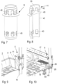
- Fig. 1 shows a plant support 1, which can also be referred to as a “bench”.
- the plant carrier 1 has an irrigation space 2 which is surrounded by a wall 3.
- the irrigation room 2 serves to accommodate plants that are arranged on a substrate, on a fleece or the like.
- the plants can grow there from an early stage, such as seeds or seedlings, into a full-grown plant and then be harvested.
- the plant carrier 1 is intended in particular to be used in a block storage or a stack storage arrangement.
- the plant carriers 1 then have spacers, not shown, which are provided with matching geometries, so that a stack of several plant carriers 1 can be arranged in the block storage.
- the plant carriers 1 then have on their lower side in the direction of gravity a running rail 4 and optionally a lighting device, not shown, with which plants in a plant carrier can be illuminated, which is arranged one position below the respective plant carrier in the direction of gravity.
- Plants require fluid, commonly referred to as “water,” to grow. Nutrients are usually transported to the plants with the water.
- the plant carrier 1 has an inlet 5 and an outlet 6.
- Inlet 5 and outlet 6 are in Fig. 2 shown enlarged.
- the process 6 is in connection with the Fig. 3 to 6 explained in more detail.
- the inlet 5 is in connection with the Fig. 7 to 10 explained in more detail.
- the inlet 5 has an inlet space 7, which is separated from the irrigation space 2 by a wall 8.
- the irrigation room 2 has a floor 9.
- the wall 8 has several openings 10 in the area of the floor 9, through which water can flow from the inlet space 7 into the irrigation space 2.
- the wall 8 is shown here partially opened to show an inlet pipe 11, which will be explained later.
- the inlet pipe 11 is connected to a pipe 12 which projects upwards in the direction of gravity.
- This pipe 12 is intended to allow water to flow from a plant carrier arranged above the plant carrier 1 in the direction of gravity into the plant carrier 1.
- the pipe 12 can have a sleeve 13 at its upper end in the direction of gravity, into which a lower end 14 of the inlet pipe 11 ( Fig. 9 ) of a further plant carrier arranged above the plant carrier 1 in the direction of gravity can occur.
- the process 6 has a process path arrangement 15 which is in connection with the 3 and 4 is presented in more detail.
- the drainage path arrangement 15 is arranged in a drainage space 16, which is separated from the irrigation space 2 by a wall 17.
- the wall 17 points in the area of the floor 9 of the irrigation room 2 several openings 18.
- the wall 17 has an overflow 44, which can also be designed as an opening, for example.
- the flow path arrangement 15 has a first flow path 19, the beginning of which is in Fig. 4 is shown in dashed lines. In the first drainage path 19, the water can flow with a flow direction that is in the in Fig. 4 The area shown in dashed lines is directed from right to left.
- the drain path arrangement 15 also has a second drain path 20, in which the draining water is guided in an arc and which opens into the first drain path 19 with an opening 21. In the area of the mouth 21, the water flowing through the second drainage path 20 has a flow direction with a component that is opposite to the flow direction in the first drainage path 19.
- the first drain path 19 and the second drain path 20 are separated from each other by baffles 22.
- the second drain path 20 has a guide wall 23 facing away from the first drain path 19, which has a straight section and a curved section which has a curvature angle in the range of 150 to 180 °.
- the first flow path 19 has a first section 24, a second section 25 and a third section 26.
- the three sections 24-26 are connected in series in the direction of flow, i.e. arranged one behind the other. However, the three sections 24-26 are arranged next to each other, so that the water flowing through the first drainage pad 19 has to change direction twice by approximately 180 ° in order to be able to flow completely through the drainage path arrangement 15.
- mouths 21 are also provided, so that a throttling of the flow of the outflowing water can also be achieved in the second section 25 and in the third section 26, this throttling, i.e. a Slowing down of the flow velocity is not caused by a narrowing of the cross section.
- the cross sections can be chosen to be relatively large. This also applies to the size of the openings 18 in the wall 17. This prevents the risk of the drain being blocked by plant residues, such as broken roots or the like, or by dirt particles.
- the second drain path 22 is also arranged in the second section 24 and in the third section 25 parallel to the first drain path 19 and can accordingly have a braking effect over the entire flow length of the drain path arrangement 15. You can therefore ensure that the water drains very slowly from the irrigation room 2 without the need for valves. The time that the water needs to completely flow out of the irrigation space 2 can be set relatively precisely by appropriately dimensioning the drainage path arrangement 15.
- the drain 6 has a drain opening 28 which is formed in the floor 9 of the irrigation room 2.
- An impact head device 29 is arranged in the drain opening 28 and is connected to the drain path arrangement 15.
- the impact head arrangement 29 has an impact head 30, the surface 31 of which is connected to a first channel 32 which passes through the drain opening 28. Water that flows from a plant carrier arranged further up in the direction of gravity then impacts the impact head 30 and flows further downward through the first channel 32, for example to a plant carrier arranged further down.
- the impact head device has a second channel 33, which is connected to the drain path arrangement 15 via an opening 34 in a wall 35 of the impact head device 29. Water that has flowed through the drain path arrangement 15 enters the second channel 33 through the opening 34 and can then also flow downwards to a plant support arranged further down in the direction of gravity. The water from the current plant carrier 1 does not mix in the plant carrier 1 with water from a plant carrier located above it.
- the impact head device 29 is connected to a pipe 36 directed upwards in the direction of gravity, which also has a sleeve 37 at its upper end in the direction of gravity, into which a pipe 45 connected to the impact head device 29 can enter in order to drain the water flowing out of the plant carrier 1 to the next lower plant support.
- a third drainage path is provided, which is separated from the first drainage path 19 and from the second drainage path 20 by a wall 38 which is higher than a height determined by the overflow 44.
- the wall 38 therefore has a height that is greater than a distance between the lower edge of the overflow 44 and the floor 9 of the irrigation room 2.
- the inlet pipe 11 is arranged in the inlet 5.
- the inlet pipe has a flow cross section 39 which is interrupted by a baffle plate 40.
- a wall 41 of the inlet pipe 11 has a plurality of outlet openings 42 through which the water can flow into the inlet space 7.
- the level of the water in the inlet space 7 then increases until the water can enter the inlet pipe 11 again through inlet openings 43.
- the height of the water level is determined by the distance between the lower edge of the inlet opening 43 and the bottom of the inlet space 2.
- the floor of the inlet room 7 normally corresponds to the floor 9 of the irrigation room 2.
- the flow resistance to which the water is exposed through the outlet openings 42 of the inlet pipe 11 and through the openings 10 in the wall 8 between the inlet space 7 and the irrigation space 2 is significantly smaller than the flow resistance that the drain path arrangement 15 generates.
- water is fed in through the inlet 5.
- the water flows through the pipe 12 and reaches the inlet pipe 11 and from there into the inlet space 7.
- the water then flows through the openings 10 into the irrigation space 2 and, when it reaches the inlet openings 43, also into a plant carrier which is arranged further down is.
- a relatively large volume flow can be fed into the pipe 12 of the top plant carrier 1.
- the irrigation chamber 2 cannot be overfilled because the filling level in the irrigation chamber 2 can never be greater than the water level in the inlet chamber 7, which in turn is determined by the inlet openings 43.
- the water that has entered the irrigation space 2 through the openings 10 then flows to the wall 17 and from there through the openings 18 in the wall 17 into the drainage space 16.
- the water flowing out is slowed down by the drainage path arrangement 15 so that it is in the irrigation space 2 accumulates until it reaches the overflow 44.
- the water in irrigation room 2 cannot rise any higher. Water that enters the drain space 16 via the overflow 44 can flow away directly through the impact head device 9.
- the water supply is simply interrupted.
- the water in the irrigation room 2 can then flow away, but very slowly, because the drainage path arrangement 15 exerts a significant throttling effect on the water.
- the time required for the water volume in the irrigation space 2 to exit through the drainage path arrangement 15 can be set relatively precisely. You can use this to determine how long the plants or the roots of the plants in irrigation room 2 can benefit from the water.
- the inlet 5 and the outlet 6 are arranged on the same edge of the irrigation room 2. Accordingly, all elements required for the water supply of the irrigation room 2 can be accommodated in the area of one edge.
- the second drain path 20 is connected to the first drain path 19 via a large number of mouths 21. It is advisable to use at least five mouths 21.
- Three sections 24-26 of the first drain path 19 are shown. It is expedient to use an odd number of sections so that the water can enter at one end of the drain path arrangement 15 and exit at the opposite end of the drain path arrangement 15.
Landscapes
- Life Sciences & Earth Sciences (AREA)
- Environmental Sciences (AREA)
- Engineering & Computer Science (AREA)
- Water Supply & Treatment (AREA)
- Cultivation Receptacles Or Flower-Pots, Or Pots For Seedlings (AREA)
- Hydroponics (AREA)
Priority Applications (5)
| Application Number | Priority Date | Filing Date | Title |
|---|---|---|---|
| EP22180540.1A EP4295672A1 (fr) | 2022-06-22 | 2022-06-22 | Support de plantes |
| JP2023098395A JP2024001867A (ja) | 2022-06-22 | 2023-06-15 | プラントキャリア |
| US18/212,406 US20230413739A1 (en) | 2022-06-22 | 2023-06-21 | Plant carrier |
| CN202310740891.3A CN117256463A (zh) | 2022-06-22 | 2023-06-21 | 植物支架 |
| CA3204940A CA3204940A1 (fr) | 2022-06-22 | 2023-06-22 | Support de plantes |
Applications Claiming Priority (1)
| Application Number | Priority Date | Filing Date | Title |
|---|---|---|---|
| EP22180540.1A EP4295672A1 (fr) | 2022-06-22 | 2022-06-22 | Support de plantes |
Publications (1)
| Publication Number | Publication Date |
|---|---|
| EP4295672A1 true EP4295672A1 (fr) | 2023-12-27 |
Family
ID=82214297
Family Applications (1)
| Application Number | Title | Priority Date | Filing Date |
|---|---|---|---|
| EP22180540.1A Pending EP4295672A1 (fr) | 2022-06-22 | 2022-06-22 | Support de plantes |
Country Status (5)
| Country | Link |
|---|---|
| US (1) | US20230413739A1 (fr) |
| EP (1) | EP4295672A1 (fr) |
| JP (1) | JP2024001867A (fr) |
| CN (1) | CN117256463A (fr) |
| CA (1) | CA3204940A1 (fr) |
Citations (3)
| Publication number | Priority date | Publication date | Assignee | Title |
|---|---|---|---|---|
| US1329559A (en) | 1916-02-21 | 1920-02-03 | Tesla Nikola | Valvular conduit |
| FR2382850A1 (fr) * | 1977-03-07 | 1978-10-06 | Cuvillier Gerard | Nouveau systeme d'irrigation continue pour nouveau type de bacs hydroponiques |
| FR2761575A1 (fr) * | 1997-04-07 | 1998-10-09 | Gode Et Fils R | Bac de forcage hydroponique pour la culture des endives et installation de forcage hydroponique |
Family Cites Families (11)
| Publication number | Priority date | Publication date | Assignee | Title |
|---|---|---|---|---|
| JPH0240758A (ja) * | 1988-07-29 | 1990-02-09 | Fujitsu Ltd | パラメタ解析方式 |
| US6243985B1 (en) * | 1999-04-08 | 2001-06-12 | Julius Miller | Automatic watering system |
| US20130247462A1 (en) * | 2010-09-29 | 2013-09-26 | Vertical Farm Systems Pty Ltd | Watering and Drainage Arrangement for a Multi-Layer Horticultural Structure |
| WO2014190797A1 (fr) * | 2013-05-30 | 2014-12-04 | 海尔集团公司 | Casier de support de légume |
| US20150282444A1 (en) * | 2014-04-04 | 2015-10-08 | Gregory S. Butler | Hydroponic flood table |
| US10214991B2 (en) * | 2015-08-13 | 2019-02-26 | Packers Plus Energy Services Inc. | Inflow control device for wellbore operations |
| CA3042932C (fr) * | 2016-10-15 | 2023-08-22 | Fujian Sanan Sino-Science Photobiotech Co., Ltd. | Unite et systeme de culture hydroponique |
| EP3654762A4 (fr) * | 2017-07-18 | 2021-07-14 | Kalera, Inc. | Appareil, système et procédé d'hydroponie |
| CN213719047U (zh) * | 2020-10-10 | 2021-07-20 | 福建省中科生物股份有限公司 | 一种机械控制潮汐灌溉的栽培床 |
| EP4062748A1 (fr) * | 2021-03-25 | 2022-09-28 | Jungheinrich Aktiengesellschaft | Alimentation en liquide d'un élément de magasin |
| US11719236B2 (en) * | 2021-06-17 | 2023-08-08 | United States Department Of Energy | Flow control valve |
-
2022
- 2022-06-22 EP EP22180540.1A patent/EP4295672A1/fr active Pending
-
2023
- 2023-06-15 JP JP2023098395A patent/JP2024001867A/ja active Pending
- 2023-06-21 US US18/212,406 patent/US20230413739A1/en active Pending
- 2023-06-21 CN CN202310740891.3A patent/CN117256463A/zh active Pending
- 2023-06-22 CA CA3204940A patent/CA3204940A1/fr active Pending
Patent Citations (3)
| Publication number | Priority date | Publication date | Assignee | Title |
|---|---|---|---|---|
| US1329559A (en) | 1916-02-21 | 1920-02-03 | Tesla Nikola | Valvular conduit |
| FR2382850A1 (fr) * | 1977-03-07 | 1978-10-06 | Cuvillier Gerard | Nouveau systeme d'irrigation continue pour nouveau type de bacs hydroponiques |
| FR2761575A1 (fr) * | 1997-04-07 | 1998-10-09 | Gode Et Fils R | Bac de forcage hydroponique pour la culture des endives et installation de forcage hydroponique |
Also Published As
| Publication number | Publication date |
|---|---|
| CA3204940A1 (fr) | 2023-12-22 |
| CN117256463A (zh) | 2023-12-22 |
| JP2024001867A (ja) | 2024-01-10 |
| US20230413739A1 (en) | 2023-12-28 |
Similar Documents
| Publication | Publication Date | Title |
|---|---|---|
| EP2180102B1 (fr) | Régulateur de débit | |
| DE60106312T2 (de) | Fluidregelvorrichtung | |
| DE2856255A1 (de) | Steuerkoerper fuer sanitaere einhebel- mischbatterien | |
| EP3649300B1 (fr) | Régulateur de jet | |
| EP0216993A1 (fr) | Organe de réglage pour gaz et liquides | |
| DE8108744U1 (de) | Sävorrichtung mit pneumatischem Saatgutejektor, insbesondere für Gemüsekulturen | |
| DE102013004076B4 (de) | Strahlregler mit Prallfläche und Ringwandung | |
| EP3327366A1 (fr) | Sortie d'air permettant le reglage de la temperature d'une chambre | |
| WO2011006691A1 (fr) | Caisse de tête pour une machine de fabrication dune bande de matière fibreuse | |
| WO2010145871A2 (fr) | Caisse de tête pour une machine servant à fabriquer une bande de matière fibreuse | |
| EP1812167B1 (fr) | Element de sortie a jet pour de la robinetterie sanitaire | |
| DE102009011345B4 (de) | Strahlregler | |
| EP3453805A1 (fr) | Répartiteur d'eau de chasse | |
| EP4295672A1 (fr) | Support de plantes | |
| DE3880176T2 (de) | Vorrichtung zum ableiten von kondensat. | |
| DE4437181C2 (de) | Stoffauflauf für eine Papiermaschine | |
| EP3199715B1 (fr) | Trop-plein pour un bac, en particulier évier | |
| EP3587943B1 (fr) | Dispositif d'aération et de mise en température d'une pièce dans un bâtiment | |
| DE10245154A1 (de) | Stoffauflauf | |
| DE1454656C3 (de) | Deckenkonstruktion | |
| EP3910118A1 (fr) | Agencement de vidange | |
| EP0826818A2 (fr) | Procédé et dispositif pour régler le profil de la consistance et de l'orientation des fibres dans une caisse de tête | |
| DE3823459C1 (en) | Throughflow body | |
| DE102017120517B4 (de) | Strahlregler | |
| DE10148123A1 (de) | Deckenauslass |
Legal Events
| Date | Code | Title | Description |
|---|---|---|---|
| PUAI | Public reference made under article 153(3) epc to a published international application that has entered the european phase |
Free format text: ORIGINAL CODE: 0009012 |
|
| STAA | Information on the status of an ep patent application or granted ep patent |
Free format text: STATUS: REQUEST FOR EXAMINATION WAS MADE |
|
| 17P | Request for examination filed |
Effective date: 20230411 |
|
| AK | Designated contracting states |
Kind code of ref document: A1 Designated state(s): AL AT BE BG CH CY CZ DE DK EE ES FI FR GB GR HR HU IE IS IT LI LT LU LV MC MK MT NL NO PL PT RO RS SE SI SK SM TR |