EP4295063B1 - Pneumatische stillwellendichtung - Google Patents
Pneumatische stillwellendichtung Download PDFInfo
- Publication number
- EP4295063B1 EP4295063B1 EP23734440.3A EP23734440A EP4295063B1 EP 4295063 B1 EP4295063 B1 EP 4295063B1 EP 23734440 A EP23734440 A EP 23734440A EP 4295063 B1 EP4295063 B1 EP 4295063B1
- Authority
- EP
- European Patent Office
- Prior art keywords
- flexible band
- central region
- shaft
- seal
- standstill seal
- Prior art date
- Legal status (The legal status is an assumption and is not a legal conclusion. Google has not performed a legal analysis and makes no representation as to the accuracy of the status listed.)
- Active
Links
Images







Classifications
-
- F—MECHANICAL ENGINEERING; LIGHTING; HEATING; WEAPONS; BLASTING
- F16—ENGINEERING ELEMENTS AND UNITS; GENERAL MEASURES FOR PRODUCING AND MAINTAINING EFFECTIVE FUNCTIONING OF MACHINES OR INSTALLATIONS; THERMAL INSULATION IN GENERAL
- F16J—PISTONS; CYLINDERS; SEALINGS
- F16J15/00—Sealings
- F16J15/002—Sealings comprising at least two sealings in succession
- F16J15/008—Sealings comprising at least two sealings in succession with provision to put out of action at least one sealing; One sealing sealing only on standstill; Emergency or servicing sealings
-
- F—MECHANICAL ENGINEERING; LIGHTING; HEATING; WEAPONS; BLASTING
- F16—ENGINEERING ELEMENTS AND UNITS; GENERAL MEASURES FOR PRODUCING AND MAINTAINING EFFECTIVE FUNCTIONING OF MACHINES OR INSTALLATIONS; THERMAL INSULATION IN GENERAL
- F16J—PISTONS; CYLINDERS; SEALINGS
- F16J15/00—Sealings
- F16J15/02—Sealings between relatively-stationary surfaces
- F16J15/021—Sealings between relatively-stationary surfaces with elastic packing
- F16J15/028—Sealings between relatively-stationary surfaces with elastic packing the packing being mechanically expanded against the sealing surface
-
- F—MECHANICAL ENGINEERING; LIGHTING; HEATING; WEAPONS; BLASTING
- F16—ENGINEERING ELEMENTS AND UNITS; GENERAL MEASURES FOR PRODUCING AND MAINTAINING EFFECTIVE FUNCTIONING OF MACHINES OR INSTALLATIONS; THERMAL INSULATION IN GENERAL
- F16J—PISTONS; CYLINDERS; SEALINGS
- F16J15/00—Sealings
- F16J15/02—Sealings between relatively-stationary surfaces
- F16J15/06—Sealings between relatively-stationary surfaces with solid packing compressed between sealing surfaces
- F16J15/10—Sealings between relatively-stationary surfaces with solid packing compressed between sealing surfaces with non-metallic packing
- F16J15/104—Sealings between relatively-stationary surfaces with solid packing compressed between sealing surfaces with non-metallic packing characterised by structure
-
- F—MECHANICAL ENGINEERING; LIGHTING; HEATING; WEAPONS; BLASTING
- F16—ENGINEERING ELEMENTS AND UNITS; GENERAL MEASURES FOR PRODUCING AND MAINTAINING EFFECTIVE FUNCTIONING OF MACHINES OR INSTALLATIONS; THERMAL INSULATION IN GENERAL
- F16J—PISTONS; CYLINDERS; SEALINGS
- F16J15/00—Sealings
- F16J15/16—Sealings between relatively-moving surfaces
- F16J15/18—Sealings between relatively-moving surfaces with stuffing-boxes for elastic or plastic packings
- F16J15/184—Tightening mechanisms
- F16J15/185—Tightening mechanisms with continuous adjustment of the compression of the packing
- F16J15/186—Tightening mechanisms with continuous adjustment of the compression of the packing using springs
-
- F—MECHANICAL ENGINEERING; LIGHTING; HEATING; WEAPONS; BLASTING
- F16—ENGINEERING ELEMENTS AND UNITS; GENERAL MEASURES FOR PRODUCING AND MAINTAINING EFFECTIVE FUNCTIONING OF MACHINES OR INSTALLATIONS; THERMAL INSULATION IN GENERAL
- F16J—PISTONS; CYLINDERS; SEALINGS
- F16J15/00—Sealings
- F16J15/16—Sealings between relatively-moving surfaces
- F16J15/32—Sealings between relatively-moving surfaces with elastic sealings, e.g. O-rings
- F16J15/3204—Sealings between relatively-moving surfaces with elastic sealings, e.g. O-rings with at least one lip
- F16J15/3208—Sealings between relatively-moving surfaces with elastic sealings, e.g. O-rings with at least one lip provided with tension elements, e.g. elastic rings
- F16J15/3212—Sealings between relatively-moving surfaces with elastic sealings, e.g. O-rings with at least one lip provided with tension elements, e.g. elastic rings with metal springs
-
- F—MECHANICAL ENGINEERING; LIGHTING; HEATING; WEAPONS; BLASTING
- F16—ENGINEERING ELEMENTS AND UNITS; GENERAL MEASURES FOR PRODUCING AND MAINTAINING EFFECTIVE FUNCTIONING OF MACHINES OR INSTALLATIONS; THERMAL INSULATION IN GENERAL
- F16J—PISTONS; CYLINDERS; SEALINGS
- F16J15/00—Sealings
- F16J15/16—Sealings between relatively-moving surfaces
- F16J15/32—Sealings between relatively-moving surfaces with elastic sealings, e.g. O-rings
- F16J15/3204—Sealings between relatively-moving surfaces with elastic sealings, e.g. O-rings with at least one lip
- F16J15/322—Sealings between relatively-moving surfaces with elastic sealings, e.g. O-rings with at least one lip supported in a direction perpendicular to the surfaces
-
- F—MECHANICAL ENGINEERING; LIGHTING; HEATING; WEAPONS; BLASTING
- F16—ENGINEERING ELEMENTS AND UNITS; GENERAL MEASURES FOR PRODUCING AND MAINTAINING EFFECTIVE FUNCTIONING OF MACHINES OR INSTALLATIONS; THERMAL INSULATION IN GENERAL
- F16J—PISTONS; CYLINDERS; SEALINGS
- F16J15/00—Sealings
- F16J15/16—Sealings between relatively-moving surfaces
- F16J15/34—Sealings between relatively-moving surfaces with slip-ring pressed against a more or less radial face on one member
- F16J15/3436—Pressing means
- F16J15/3448—Pressing means the pressing force resulting from fluid pressure
-
- F—MECHANICAL ENGINEERING; LIGHTING; HEATING; WEAPONS; BLASTING
- F16—ENGINEERING ELEMENTS AND UNITS; GENERAL MEASURES FOR PRODUCING AND MAINTAINING EFFECTIVE FUNCTIONING OF MACHINES OR INSTALLATIONS; THERMAL INSULATION IN GENERAL
- F16J—PISTONS; CYLINDERS; SEALINGS
- F16J15/00—Sealings
- F16J15/16—Sealings between relatively-moving surfaces
- F16J15/34—Sealings between relatively-moving surfaces with slip-ring pressed against a more or less radial face on one member
- F16J15/38—Sealings between relatively-moving surfaces with slip-ring pressed against a more or less radial face on one member sealed by a packing
-
- F—MECHANICAL ENGINEERING; LIGHTING; HEATING; WEAPONS; BLASTING
- F16—ENGINEERING ELEMENTS AND UNITS; GENERAL MEASURES FOR PRODUCING AND MAINTAINING EFFECTIVE FUNCTIONING OF MACHINES OR INSTALLATIONS; THERMAL INSULATION IN GENERAL
- F16J—PISTONS; CYLINDERS; SEALINGS
- F16J15/00—Sealings
- F16J15/46—Sealings with packing ring expanded or pressed into place by fluid pressure, e.g. inflatable packings
Definitions
- the invention relates to standstill seals, and more particularly, to pressure-driven standstill seals that are applicable for sealing against high pressure differentials.
- one approach is to provide a solid, rigid sealing annulus 100 that surrounds the shaft 102 and can be pressed axially into contact with a radial structure 104 that is sealed to the shaft 102 via a supporting structure 106.
- the sealing annulus 100 is pneumatically driven against the radial structure 104 when the shaft 102 is not rotating, and is withdrawn from the shaft 102 by a spring 108 when the shaft is rotating.
- the sealing annulus 100 is driven by a bi-directional pneumatic piston or by mechanical mechanism such as a solenoid.
- the standstill shaft seal is activated and deactivated by a controller (not shown), which may be but is not necessarily the same controller that also controls the rotational starting and stopping of the shaft.
- FIG. 1B illustrates the standstill shaft seal when it is open
- Fig. 1C illustrates the seal when it is closed.
- Figs. 1B and 1C The approach of Figs. 1B and 1C is simple, and relatively easy to manufacture. However, it can be difficult to provide complex cross-sectional shaping to the tube 110, because it is typically extruded rather than cast.
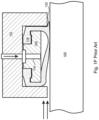
- a shaped elastomeric band 118 is snapped onto a supporting form 120 and installed within the housing 112.
- the supporting form 120 is penetrated by the inflation inlet 116, which is directed to a rear surface of the band 118.
- the elastomeric band 118 remains flat against the supporting form 120, and does not extend beyond the housing 112.
- Fig. 1D when no pressure is applied via the inflation inlet 116, the elastomeric band 118 remains flat against the supporting form 120, and does not extend beyond the housing 112.
- Document US 3 985 365 A discloses a remotely actuated emergency shaft seal.
- Document US 3 578 342 A discloses a shaft seal.
- Document US 4 342 336 A discloses a double-acting inflatable seal.
- Document JP H06 344984 A discloses a bulkhead sealing device for ship.
- the present invention is a fluid pressure driven standstill shaft seal according to appended claims that is simple in design, relatively low cost to produce, and able to form a seal that reliably withstands high pressure process fluids, such as process gasses pressurized to 70 Bar or higher.
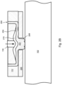
- the disclosed seal comprises a flexible band that is installed within an annular housing and surrounds a rotatable shaft.
- the flexible band comprises a thick, substantially rectangular central region flanked by thinner side regions on either side thereof.
- the thinner side regions of the flexible band provide radial or axial flexibility to the central region, such that the thick central region is able to be extended through an annular opening in the housing and then retracted therefrom.
- the thickness of the central region enables it to resist being distorted or extruded when it is pressed against the shaft and subject to a high fluid pressure differential. Pressurized control fluid is applied behind the central region via a control fluid inlet to close the standstill seal.
- the pressurized control fluid that is applied behind the flexible band is controlled by a controller, which in embodiments also controls the rotation of the shaft. While the shaft is rotating, no pressure is applied behind the central region of the flexible band, such that it remains partially or fully within the annular housing and does not contact the shaft. When the shaft is not rotating (i.e. is in a standstill condition), fluid pressure is applied by the controller behind the central region of the flexible band via the control fluid inlet. As a result, the central region of the flexible band is pushed through the annular opening in the housing, and is pressed against the shaft, or against an intermediate structure that is sealed to the shaft, forming a standstill seal therewith.
- the change in diameter of the central region is only a small percentage of the full diameter of the flexible band, such that the central region is easily able to accommodate the circumferential compression that is required as the central region is pressed radially inward toward the shaft.
- the source of the control fluid is independent of the process, and can be, for example, a source of pressurized nitrogen gas, pressurized air, or a pressurized liquid.
- the control fluid is the process fluid.
- a pressure boosting device is used to increase the pressure of the process fluid that is applied behind the flexible band.
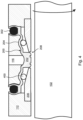
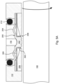
- Some of these embodiments include a pair of annular, toothed springs, each of which has a solid annular region that is clamped in place within the housing, and a toothed annular region that is beneath at least a portion of the side regions of the flexible band.
- the toothed springs provide added return force that ensures full withdrawal of the central region from the shaft.
- Embodiments further include a pair of rigid annular rings on either side of the thick central region which completely eliminate the possibility that any of the thick region might be extruded into the gap between the housing and the shaft when the standstill seal is engaged.
- the annular rings can be attached to the central region of the flexible band or they can be fixed to the housing and extend into the gap between the shaft and the housing.
- the standstill seal of the present invention can be implemented together with at least one rotating shaft seal, such as a rotating face mechanical seal.
- the standstill seal can be implemented upstream or downstream of the rotating shaft seal. Or, if a plurality of rotating shaft seals are included, then the standstill seal can be implemented between the rotating shaft seals. In some embodiments, a plurality of the disclosed standstill seals are deployed, for example one upstream of the rotating shaft seal and one downstream of the rotating shaft seal.
- the standstill seal is configured, when the controller applies the pressurized control fluid to the control fluid inlet, to extend the central region of the flexible band through the gap such that it makes contact and forms a seal with the shaft, or with an intermediate structure that is sealed to the shaft.
- the standstill seal is also configured, when the controller ceases to apply the pressurized control fluid to the flexible band, to withdraw the central region of the flexible band away from the shaft or intermediate structure.
- the standstill seal is implemented downstream of the rotating shaft seal.
- the standstill seal can be implemented between the rotating shaft seals.
- a plurality of the disclosed standstill seals are deployed, for example one upstream of a rotating shaft seal and one downstream of the rotating shaft seal.
Landscapes
- Engineering & Computer Science (AREA)
- General Engineering & Computer Science (AREA)
- Mechanical Engineering (AREA)
- Physics & Mathematics (AREA)
- Fluid Mechanics (AREA)
- Architecture (AREA)
- Sealing Devices (AREA)
- Mechanical Sealing (AREA)
- Structures Of Non-Positive Displacement Pumps (AREA)
- Gasket Seals (AREA)
- Sealing Using Fluids, Sealing Without Contact, And Removal Of Oil (AREA)
Claims (15)
- Stillstanddichtung, die dafür ausgelegt ist, eine Dichtung mit einer drehbaren Welle (102) zu bilden, um einen Austritt einer Prozessflüssigkeit nach der Stillstanddichtung zu verhindern, wenn die Welle sich nicht dreht, wobei die Stillstanddichtung umfasst:ein flexibles Band (200), das die Welle umgibt, wobei das flexible Band einen relativ dickeren Mittelbereich (202) umfasst, aus dem relativ dünnere Seitenbereiche (204) sich längs in der Richtung der Abdichtung des Mittelbereichs (202) mit der Welle (102), oder mit einer Zwischenstruktur, die an der Welle abgedichtet ist, wenn in einer axialen Querschnittsansicht gesehen, erstrecken, wobei der Mittelbereich (202) in einem Längsquerschnitt im Wesentlichen rechteckig ist;ein Gehäuse (112), das dafür ausgelegt ist, das flexible Band zu beherbergen;ein Paar Deckplatten (206), die unter den Seitenbereichen des flexiblen Bands liegen und die dafür ausgelegt sind, zu verhindern, dass die Seitenbereiche nach den Deckplatten abgelenkt werden, wobei ein Spalt (208) zwischen den Deckplatten vorgesehen ist, durch welchen der Mittelbereich (202) des flexiblen Bands ausgedehnt werden kann;einen Steuerungsflüssigkeitseinlass (116), der dafür ausgelegt ist, Flüssigkeitskommunikation zwischen einer Quelle von Drucksteuerungsflüssigkeit und einer hinteren Fläche des flexiblen Bands zu liefern; undein Steuergerät;wobei die Stillstanddichtung dafür ausgelegt ist, wenn das Steuergerät die Drucksteuerungsflüssigkeit auf den Steuerungsflüssigkeitseinlass (116) aufbringt, die hintere Fläche des flexiblen Bands (200) zu dem Spalt (208) hin zu drücken, wodurch der Mittelbereich (202) des flexiblen Bands durch den Spalt derart ausgedehnt wird, dass er einen Kontakt herstellt und eine Dichtung mit der Welle (102), oder mit der Zwischenstruktur, die an der Welle abgedichtet ist, bildet, wodurch Flexibilität des flexiblen Bandes (200) durch die Seitenbereiche (204) geliefert wird;wobei die Stillstanddichtung dafür ausgelegt ist, wenn das Steuergerät aufhört, die Drucksteuerungsflüssigkeit auf den Steuerungsflüssigkeitseinlass (116) aufzubringen, den Mittelbereich (202) des flexiblen Bands weg von der Welle (102) oder Zwischenstruktur zurückzuziehen.
- Stillstanddichtung nach Anspruch 1, worin das flexible Band (200) ausreichende Elastizität aufweist, um zu bewirken, dass der Mittelbereich (202) aus der Welle (102) oder Zwischenstruktur zurückgezogen wird, wenn das Steuergerät aufhört, die Drucksteuerungsflüssigkeit auf das flexible Band aufzubringen.
- Stillstanddichtung nach einem der vorhergehenden Ansprüche, worin die Seitenbereiche des flexiblen Bandes (200) Abschnitte umfassen, die im Längsquerschnitt gekrümmt sind, wodurch eine Ausdehnung der Seitenbereiche (204) ermöglicht wird, wenn der Mittelbereich (202) durch den Spalt (208) ausgedehnt wird.
- Stillstanddichtung nach einem der vorhergehenden Ansprüche, worin das Steuergerät dafür ausgelegt ist, die Drehung der Welle (102) zu starten und zu stoppen, sowie die Aufbringung der Drucksteuerungsflüssigkeit auf das flexible Band (200) zu steuern.
- Stillstanddichtung nach einem der vorhergehenden Ansprüche, ferner umfassend ein Paar starre ringförmige Stützringe (500), die dafür ausgelegt sind, Seiten des Mittelbereichs (202) des flexiblen Bandes (200) zu stützen, wenn der Mittelbereich durch den Spalt (208) zwischen den Deckplatten (206) ausgedehnt ist.
- Stillstanddichtung nach Anspruch 5, worin die ringförmigen Stützringe (500) am Mittelbereich (202) des flexiblen Bandes (200) befestigt sind.
- Stillstanddichtung nach Anspruch 5, worin die ringförmigen Stützringe (500) sich aus dem Gehäuse (112) erstrecken.
- Stillstanddichtung nach einem der vorhergehenden Ansprüche, ferner umfassend eine Feder (300), die dafür ausgelegt ist, den Rückzug des Mittelbereichs (202) des flexiblen Bandes (200) aus der Welle (102) oder Zwischenstruktur zu unterstützen, wenn das Steuergerät aufhört, die Drucksteuerungsflüssigkeit auf das flexible Band aufzubringen.
- Stillstanddichtung nach einem der vorhergehenden Ansprüche, worin die Stillstanddichtung dafür ausgelegt ist, den Mittelbereich (202) des flexiblen Bandes (200) radial nach innen gegen die Welle (102) oder gegen die Zwischenstruktur aufzubringen.
- Stillstanddichtung nach einem der vorhergehenden Ansprüche, worin die Stillstanddichtung dafür ausgelegt ist, den Mittelbereich (202) des flexiblen Bandes (200) axial gegen die Zwischenstruktur aufzubringen.
- Stillstanddichtung nach Anspruch 5 oder nach Anspruch 6, worin:die Stillstanddichtung dafür ausgelegt ist, den Mittelbereich (202) des flexiblen Bandes (200) radial nach innen gegen die Welle (102) oder gegen die Zwischenstruktur aufzubringen; unddie ringförmigen Stützringe (500) Ringspalte (506) aufweisen, die den ringförmigen Stützringen ermöglichen, sich radial zusammenzudrücken, wenn der Mittelbereich (202) radial nach innen gegen die Welle (102) oder gegen die Zwischenstruktur ausgedehnt ist.
- Stillstanddichtung nach Anspruch 11, worin die Stillstanddichtung ferner Druckfeder (508) umfasst, die auf die Spalte (506) in den Stützringen (500) aufgebracht sind, wobei die Druckfeder dafür ausgelegt sind, den Rückzug des Mittelbereichs (202) des flexiblen Bandes (200) aus der Welle (102) oder Zwischenstruktur zu unterstützen, wenn das Steuergerät aufhört, die Drucksteuerungsflüssigkeit auf das flexible Band aufzubringen.
- Stillstanddichtung nach Anspruch 8, worin:die Stillstanddichtung dafür ausgelegt ist, den Mittelbereich (202) des flexiblen Bandes (200) radial nach innen gegen die Welle (102) oder gegen die Zwischenstruktur aufzubringen; unddie Feder (300) ein Paar beabstandete ringförmige Bänder umfasst, die massive ringförmige Abschnitte (304) aufweisen, aus denen Zähne (306) sich axial zueinander unterhalb der Seitenbereiche des flexiblen Bandes (200) erstrecken, wobei ein axialer Spalt (800) zwischen den Zähnen vorgesehen ist, durch welchen der Mittelbereich des flexiblen Bandes ausgedehnt werden kann, um die Welle (102) oder die Zwischenstruktur zu kontaktieren, wobei die Zähne radial nach innen gebogen werden, während der Mittelbereich (202) des flexiblen Bandes zu der Welle hin gedrückt wird.
- Stillstanddichtung nach einem der Ansprüche 1-4, worin:die Stillstanddichtung dafür ausgelegt ist, den Mittelbereich (202) des flexiblen Bandes (200) radial nach innen gegen die Welle (102) oder gegen die Zwischenstruktur aufzubringen;die Stillstanddichtung eine Feder (300) umfasst, die dafür ausgelegt ist, den Rückzug des Mittelbereichs (202) des flexiblen Bandes (200) aus der Welle (102) oder Zwischenstruktur zu unterstützen, wenn das Steuergerät aufhört, die Drucksteuerungsflüssigkeit auf das flexible Band aufzubringen; unddie Stillstanddichtung ferner ein Paar starre ringförmige Stützringe (500) umfasst, die dafür ausgelegt sind, Seiten des Mittelbereichs (202) des flexiblen Bandes (200) zu stützen, wenn der Mittelbereich durch den Spalt (208) zwischen den Deckplatten (206) ausgedehnt ist, wobei die genannten starren ringförmigen Stützringe sich radial nach innen aus den Federn erstrecken.
- Stillstanddichtung nach einem der Ansprüche 1-4, worin:die Stillstanddichtung dafür ausgelegt ist, den Mittelbereich (202) des flexiblen Bandes (200) axial gegen die Zwischenstruktur aufzubringen; unddie Stillstanddichtung ferner eine Feder (300) umfasst, die dafür ausgelegt ist, den Rückzug des Mittelbereichs (202) des flexiblen Bandes (200) aus der Welle (102) oder Zwischenstruktur zu unterstützen, wenn das Steuergerät aufhört, die Drucksteuerungsflüssigkeit auf das flexible Band aufzubringen;die Feder (300) ein Paar radial konzentrisch ringförmige Scheiben umfasst, die massive ringförmige Abschnitte (304) aufweisen, aus denen Zähne (306) sich radial nach innen und nach außen zueinander unterhalb der Seitenbereiche (204) des flexiblen Bandes (200) erstrecken, wobei ein axialer Spalt zwischen den radial inneren und den radial äußeren Zähnen vorgesehen ist, durch welchen der Mittelbereich (200) des flexiblen Bandes ausgedehnt werden kann, um die Zwischenstruktur zu kontaktieren, wobei die Zähne (306) axial gebogen sind, während der Mittelbereich (202) des flexiblen Bandes (200) zu der Welle (102) hin gedrückt wird.
Applications Claiming Priority (2)
| Application Number | Priority Date | Filing Date | Title |
|---|---|---|---|
| US17/742,851 US12129928B2 (en) | 2022-05-12 | 2022-05-12 | Pneumatic standstill shaft seal |
| PCT/IB2023/054584 WO2023218290A1 (en) | 2022-05-12 | 2023-05-03 | Pneumatic standstill shaft seal |
Publications (4)
| Publication Number | Publication Date |
|---|---|
| EP4295063A1 EP4295063A1 (de) | 2023-12-27 |
| EP4295063A4 EP4295063A4 (de) | 2024-05-29 |
| EP4295063C0 EP4295063C0 (de) | 2025-07-02 |
| EP4295063B1 true EP4295063B1 (de) | 2025-07-02 |
Family
ID=88236872
Family Applications (1)
| Application Number | Title | Priority Date | Filing Date |
|---|---|---|---|
| EP23734440.3A Active EP4295063B1 (de) | 2022-05-12 | 2023-05-03 | Pneumatische stillwellendichtung |
Country Status (7)
| Country | Link |
|---|---|
| US (1) | US12129928B2 (de) |
| EP (1) | EP4295063B1 (de) |
| JP (1) | JP7637799B2 (de) |
| KR (1) | KR102898455B1 (de) |
| CN (1) | CN117396691A (de) |
| AU (1) | AU2023203937B2 (de) |
| WO (1) | WO2023218290A1 (de) |
Family Cites Families (24)
| Publication number | Priority date | Publication date | Assignee | Title |
|---|---|---|---|---|
| US3124502A (en) * | 1964-03-10 | Composite fibrous lubricant packing | ||
| US2548412A (en) * | 1948-05-24 | 1951-04-10 | Hinderliter Tool Company Divis | Sealing unit for well casing heads |
| DE933842C (de) * | 1953-06-13 | 1955-10-06 | Voith Gmbh J M | Spaltdichtung |
| US3178779A (en) * | 1962-06-28 | 1965-04-20 | North American Aviation Inc | Multi-cell inflatable seal |
| US3578342A (en) | 1969-01-14 | 1971-05-11 | Satterthwaite James G | Shaft seal |
| US3689082A (en) * | 1970-02-03 | 1972-09-05 | Satterthwaite James G | Inflatable seal |
| FR2243619A5 (de) * | 1973-09-06 | 1975-04-04 | Joint Francais | |
| US3985365A (en) | 1975-11-06 | 1976-10-12 | Bartholomew Thomas Catanzaro | Remotely actuated emergency shaft seal |
| SE413200B (sv) | 1978-08-14 | 1980-04-28 | Asea Atom Ab | Tetningsanordning for tillfellig tryckavtetning |
| US4342336A (en) * | 1979-10-03 | 1982-08-03 | Satterthwaite J Glenn | Double-acting inflatable seal |
| US4381114A (en) * | 1981-11-23 | 1983-04-26 | Cameron Iron Works, Inc. | Packoff and seal ring assembly with injected plastic packing |
| JPH06100191B2 (ja) * | 1989-04-14 | 1994-12-12 | 株式会社日立製作所 | ポンプのシール装置 |
| FR2665499B1 (fr) * | 1990-07-10 | 1994-01-28 | Joint Francais | Dispositif d'etancheite a joint gonflable pour porte ou panneau mobile. |
| JPH06344984A (ja) | 1993-06-07 | 1994-12-20 | Nippon Marine Techno Kk | 船舶用隔壁シール装置 |
| JPH07239039A (ja) | 1994-02-28 | 1995-09-12 | Ntn Corp | 回転軸の密封装置 |
| US5524905A (en) * | 1994-09-28 | 1996-06-11 | Greene, Tweed Of Delaware, Inc. | Sealing assembly with T-shaped seal ring and anti-extrusion rings |
| US5890535A (en) * | 1997-07-23 | 1999-04-06 | Abb Vetco Gray Inc. | Diverter flow line seal |
| US6942224B2 (en) * | 2003-07-16 | 2005-09-13 | Steris Inc. | Inflatable seal |
| US10077621B2 (en) * | 2013-06-13 | 2018-09-18 | Vetco Gray, LLC | Diverter flow line insert packer seal |
| CN105298553B (zh) | 2014-06-17 | 2018-03-06 | 斗山重工业株式会社 | 刷式密封组件 |
| US10316604B2 (en) * | 2014-07-02 | 2019-06-11 | Utex Industries, Inc. | Inflatable seal with fabric expansion restriction |
| MX380065B (es) | 2014-12-08 | 2025-03-11 | Flowserve Pte Ltd | Sello aislante de cojinete con interfaz de junta toroidal ahusada de cierre estático |
| CN206988432U (zh) | 2017-07-27 | 2018-02-09 | 浙江长江搅拌设备有限公司 | 一种机械密封的堵流装置 |
| US11506217B2 (en) | 2020-01-21 | 2022-11-22 | John Crane Uk Limited | Porous carbon containment or separation seal |
-
2022
- 2022-05-12 US US17/742,851 patent/US12129928B2/en active Active
-
2023
- 2023-05-03 AU AU2023203937A patent/AU2023203937B2/en active Active
- 2023-05-03 KR KR1020237029915A patent/KR102898455B1/ko active Active
- 2023-05-03 EP EP23734440.3A patent/EP4295063B1/de active Active
- 2023-05-03 CN CN202380009849.2A patent/CN117396691A/zh active Pending
- 2023-05-03 JP JP2023571795A patent/JP7637799B2/ja active Active
- 2023-05-03 WO PCT/IB2023/054584 patent/WO2023218290A1/en not_active Ceased
Also Published As
| Publication number | Publication date |
|---|---|
| WO2023218290A1 (en) | 2023-11-16 |
| EP4295063A4 (de) | 2024-05-29 |
| AU2023203937A1 (en) | 2023-11-30 |
| KR102898455B1 (ko) | 2025-12-09 |
| US12129928B2 (en) | 2024-10-29 |
| US20230366469A1 (en) | 2023-11-16 |
| EP4295063C0 (de) | 2025-07-02 |
| EP4295063A1 (de) | 2023-12-27 |
| CN117396691A (zh) | 2024-01-12 |
| KR20230159391A (ko) | 2023-11-21 |
| AU2023203937B2 (en) | 2024-08-29 |
| JP2024523122A (ja) | 2024-06-28 |
| JP7637799B2 (ja) | 2025-02-28 |
Similar Documents
| Publication | Publication Date | Title |
|---|---|---|
| KR100472395B1 (ko) | 기계적씨일(seal) | |
| US9376884B2 (en) | Packing element | |
| US5454572A (en) | Mechanical end face seal system | |
| US2214261A (en) | Sealing device | |
| JPS6323430B2 (de) | ||
| EP0636821B1 (de) | Spindeldichtung für Drosselklappen | |
| KR920001237B1 (ko) | 이중 블럭-벤트 밸브 장치 | |
| US6979002B2 (en) | Sealing apparatus having sequentially engageable seals | |
| JPH0650437A (ja) | 圧力解除式シール構造 | |
| JP2013150986A5 (ja) | ろ過システムおよびスパイラル型エレメント | |
| NO171807B (no) | Spjeldventil | |
| US20100258311A1 (en) | Casing Patch and Seal | |
| US7735562B2 (en) | Tieback seal system and method | |
| EP2321561B1 (de) | Verbesserungen von federerregten kunststoffdichtungen und diese betreffend | |
| US20150115535A1 (en) | Seal having variable elastic modulus | |
| KR960703217A (ko) | 게이트 밸브(gate valve) | |
| US12129928B2 (en) | Pneumatic standstill shaft seal | |
| JPH0686918B2 (ja) | 可撓性継手手段 | |
| CN116438396A (zh) | 用于旋转轴设备的柔性密封膜和密封组件 | |
| CN114811073B (zh) | 一种密封件、包括其的密封组件和密封阀 | |
| US11448229B2 (en) | Seal assembly | |
| EP3601854B1 (de) | Mechanische stosswellendichtung | |
| CN114508603B (zh) | 密封阀 | |
| JP2574119Y2 (ja) | 密封装置 | |
| JPH0665558B2 (ja) | 隔壁シ−ル |
Legal Events
| Date | Code | Title | Description |
|---|---|---|---|
| STAA | Information on the status of an ep patent application or granted ep patent |
Free format text: STATUS: UNKNOWN |
|
| STAA | Information on the status of an ep patent application or granted ep patent |
Free format text: STATUS: THE INTERNATIONAL PUBLICATION HAS BEEN MADE |
|
| PUAI | Public reference made under article 153(3) epc to a published international application that has entered the european phase |
Free format text: ORIGINAL CODE: 0009012 |
|
| STAA | Information on the status of an ep patent application or granted ep patent |
Free format text: STATUS: REQUEST FOR EXAMINATION WAS MADE |
|
| 17P | Request for examination filed |
Effective date: 20230706 |
|
| AK | Designated contracting states |
Kind code of ref document: A1 Designated state(s): AL AT BE BG CH CY CZ DE DK EE ES FI FR GB GR HR HU IE IS IT LI LT LU LV MC ME MK MT NL NO PL PT RO RS SE SI SK SM TR |
|
| A4 | Supplementary search report drawn up and despatched |
Effective date: 20240430 |
|
| RIC1 | Information provided on ipc code assigned before grant |
Ipc: F16J 15/10 20060101ALI20240424BHEP Ipc: F16J 15/02 20060101ALI20240424BHEP Ipc: F16J 15/38 20060101ALI20240424BHEP Ipc: F16J 15/34 20060101ALI20240424BHEP Ipc: F16J 15/00 20060101ALI20240424BHEP Ipc: F16J 15/18 20060101ALI20240424BHEP Ipc: F16J 15/32 20160101ALI20240424BHEP Ipc: F16J 15/46 20060101AFI20240424BHEP |
|
| STAA | Information on the status of an ep patent application or granted ep patent |
Free format text: STATUS: EXAMINATION IS IN PROGRESS |
|
| 17Q | First examination report despatched |
Effective date: 20241008 |
|
| REG | Reference to a national code |
Ref country code: DE Ref legal event code: R079 Free format text: PREVIOUS MAIN CLASS: F16J0015460000 Ipc: F16J0015321200 Ref country code: DE Ref legal event code: R079 Ref document number: 602023004556 Country of ref document: DE Free format text: PREVIOUS MAIN CLASS: F16J0015460000 Ipc: F16J0015321200 |
|
| GRAP | Despatch of communication of intention to grant a patent |
Free format text: ORIGINAL CODE: EPIDOSNIGR1 |
|
| STAA | Information on the status of an ep patent application or granted ep patent |
Free format text: STATUS: GRANT OF PATENT IS INTENDED |
|
| RIC1 | Information provided on ipc code assigned before grant |
Ipc: F16J 15/10 20060101ALI20250304BHEP Ipc: F16J 15/02 20060101ALI20250304BHEP Ipc: F16J 15/46 20060101ALI20250304BHEP Ipc: F16J 15/38 20060101ALI20250304BHEP Ipc: F16J 15/34 20060101ALI20250304BHEP Ipc: F16J 15/00 20060101ALI20250304BHEP Ipc: F16J 15/322 20160101ALI20250304BHEP Ipc: F16J 15/3212 20160101AFI20250304BHEP |
|
| INTG | Intention to grant announced |
Effective date: 20250313 |
|
| GRAS | Grant fee paid |
Free format text: ORIGINAL CODE: EPIDOSNIGR3 |
|
| GRAA | (expected) grant |
Free format text: ORIGINAL CODE: 0009210 |
|
| STAA | Information on the status of an ep patent application or granted ep patent |
Free format text: STATUS: THE PATENT HAS BEEN GRANTED |
|
| DAV | Request for validation of the european patent (deleted) | ||
| DAX | Request for extension of the european patent (deleted) | ||
| AK | Designated contracting states |
Kind code of ref document: B1 Designated state(s): AL AT BE BG CH CY CZ DE DK EE ES FI FR GB GR HR HU IE IS IT LI LT LU LV MC ME MK MT NL NO PL PT RO RS SE SI SK SM TR |
|
| REG | Reference to a national code |
Ref country code: GB Ref legal event code: FG4D |
|
| REG | Reference to a national code |
Ref country code: CH Ref legal event code: EP |
|
| REG | Reference to a national code |
Ref country code: IE Ref legal event code: FG4D |
|
| U01 | Request for unitary effect filed |
Effective date: 20250708 |
|
| U07 | Unitary effect registered |
Designated state(s): AT BE BG DE DK EE FI FR IT LT LU LV MT NL PT RO SE SI Effective date: 20250711 |
|
| PG25 | Lapsed in a contracting state [announced via postgrant information from national office to epo] |
Ref country code: IS Free format text: LAPSE BECAUSE OF FAILURE TO SUBMIT A TRANSLATION OF THE DESCRIPTION OR TO PAY THE FEE WITHIN THE PRESCRIBED TIME-LIMIT Effective date: 20251102 |
|
| PG25 | Lapsed in a contracting state [announced via postgrant information from national office to epo] |
Ref country code: NO Free format text: LAPSE BECAUSE OF FAILURE TO SUBMIT A TRANSLATION OF THE DESCRIPTION OR TO PAY THE FEE WITHIN THE PRESCRIBED TIME-LIMIT Effective date: 20251002 |
|
| PG25 | Lapsed in a contracting state [announced via postgrant information from national office to epo] |
Ref country code: HR Free format text: LAPSE BECAUSE OF FAILURE TO SUBMIT A TRANSLATION OF THE DESCRIPTION OR TO PAY THE FEE WITHIN THE PRESCRIBED TIME-LIMIT Effective date: 20250702 |
|
| PG25 | Lapsed in a contracting state [announced via postgrant information from national office to epo] |
Ref country code: GR Free format text: LAPSE BECAUSE OF FAILURE TO SUBMIT A TRANSLATION OF THE DESCRIPTION OR TO PAY THE FEE WITHIN THE PRESCRIBED TIME-LIMIT Effective date: 20251003 |
|
| PG25 | Lapsed in a contracting state [announced via postgrant information from national office to epo] |
Ref country code: CZ Free format text: LAPSE BECAUSE OF FAILURE TO SUBMIT A TRANSLATION OF THE DESCRIPTION OR TO PAY THE FEE WITHIN THE PRESCRIBED TIME-LIMIT Effective date: 20250702 |
|
| PG25 | Lapsed in a contracting state [announced via postgrant information from national office to epo] |
Ref country code: PL Free format text: LAPSE BECAUSE OF FAILURE TO SUBMIT A TRANSLATION OF THE DESCRIPTION OR TO PAY THE FEE WITHIN THE PRESCRIBED TIME-LIMIT Effective date: 20250702 |
|
| PG25 | Lapsed in a contracting state [announced via postgrant information from national office to epo] |
Ref country code: RS Free format text: LAPSE BECAUSE OF FAILURE TO SUBMIT A TRANSLATION OF THE DESCRIPTION OR TO PAY THE FEE WITHIN THE PRESCRIBED TIME-LIMIT Effective date: 20251002 |
|
| PG25 | Lapsed in a contracting state [announced via postgrant information from national office to epo] |
Ref country code: ES Free format text: LAPSE BECAUSE OF FAILURE TO SUBMIT A TRANSLATION OF THE DESCRIPTION OR TO PAY THE FEE WITHIN THE PRESCRIBED TIME-LIMIT Effective date: 20250702 |
|
| PG25 | Lapsed in a contracting state [announced via postgrant information from national office to epo] |
Ref country code: SM Free format text: LAPSE BECAUSE OF FAILURE TO SUBMIT A TRANSLATION OF THE DESCRIPTION OR TO PAY THE FEE WITHIN THE PRESCRIBED TIME-LIMIT Effective date: 20250702 |
|
| PG25 | Lapsed in a contracting state [announced via postgrant information from national office to epo] |
Ref country code: SK Free format text: LAPSE BECAUSE OF FAILURE TO SUBMIT A TRANSLATION OF THE DESCRIPTION OR TO PAY THE FEE WITHIN THE PRESCRIBED TIME-LIMIT Effective date: 20250702 |
|
| PLBE | No opposition filed within time limit |
Free format text: ORIGINAL CODE: 0009261 |
|
| STAA | Information on the status of an ep patent application or granted ep patent |
Free format text: STATUS: NO OPPOSITION FILED WITHIN TIME LIMIT |