EP4293247A2 - Elektrische feststellbremsvorrichtung - Google Patents
Elektrische feststellbremsvorrichtung Download PDFInfo
- Publication number
- EP4293247A2 EP4293247A2 EP23207058.1A EP23207058A EP4293247A2 EP 4293247 A2 EP4293247 A2 EP 4293247A2 EP 23207058 A EP23207058 A EP 23207058A EP 4293247 A2 EP4293247 A2 EP 4293247A2
- Authority
- EP
- European Patent Office
- Prior art keywords
- screw shaft
- brake cable
- brake
- cylindrical portion
- rotation restricting
- Prior art date
- Legal status (The legal status is an assumption and is not a legal conclusion. Google has not performed a legal analysis and makes no representation as to the accuracy of the status listed.)
- Pending
Links
- 238000003780 insertion Methods 0.000 claims description 25
- 230000037431 insertion Effects 0.000 claims description 25
- 238000006243 chemical reaction Methods 0.000 claims description 15
- 230000008602 contraction Effects 0.000 description 11
- 210000000078 claw Anatomy 0.000 description 2
- 230000002093 peripheral effect Effects 0.000 description 2
- 230000006835 compression Effects 0.000 description 1
- 238000007906 compression Methods 0.000 description 1
- 230000000694 effects Effects 0.000 description 1
- 238000003466 welding Methods 0.000 description 1
Images


Classifications
-
- B—PERFORMING OPERATIONS; TRANSPORTING
- B60—VEHICLES IN GENERAL
- B60T—VEHICLE BRAKE CONTROL SYSTEMS OR PARTS THEREOF; BRAKE CONTROL SYSTEMS OR PARTS THEREOF, IN GENERAL; ARRANGEMENT OF BRAKING ELEMENTS ON VEHICLES IN GENERAL; PORTABLE DEVICES FOR PREVENTING UNWANTED MOVEMENT OF VEHICLES; VEHICLE MODIFICATIONS TO FACILITATE COOLING OF BRAKES
- B60T13/00—Transmitting braking action from initiating means to ultimate brake actuator with power assistance or drive; Brake systems incorporating such transmitting means, e.g. air-pressure brake systems
- B60T13/74—Transmitting braking action from initiating means to ultimate brake actuator with power assistance or drive; Brake systems incorporating such transmitting means, e.g. air-pressure brake systems with electrical assistance or drive
- B60T13/741—Transmitting braking action from initiating means to ultimate brake actuator with power assistance or drive; Brake systems incorporating such transmitting means, e.g. air-pressure brake systems with electrical assistance or drive acting on an ultimate actuator
-
- B—PERFORMING OPERATIONS; TRANSPORTING
- B60—VEHICLES IN GENERAL
- B60T—VEHICLE BRAKE CONTROL SYSTEMS OR PARTS THEREOF; BRAKE CONTROL SYSTEMS OR PARTS THEREOF, IN GENERAL; ARRANGEMENT OF BRAKING ELEMENTS ON VEHICLES IN GENERAL; PORTABLE DEVICES FOR PREVENTING UNWANTED MOVEMENT OF VEHICLES; VEHICLE MODIFICATIONS TO FACILITATE COOLING OF BRAKES
- B60T13/00—Transmitting braking action from initiating means to ultimate brake actuator with power assistance or drive; Brake systems incorporating such transmitting means, e.g. air-pressure brake systems
- B60T13/74—Transmitting braking action from initiating means to ultimate brake actuator with power assistance or drive; Brake systems incorporating such transmitting means, e.g. air-pressure brake systems with electrical assistance or drive
- B60T13/746—Transmitting braking action from initiating means to ultimate brake actuator with power assistance or drive; Brake systems incorporating such transmitting means, e.g. air-pressure brake systems with electrical assistance or drive and mechanical transmission of the braking action
-
- D—TEXTILES; PAPER
- D07—ROPES; CABLES OTHER THAN ELECTRIC
- D07B—ROPES OR CABLES IN GENERAL
- D07B1/00—Constructional features of ropes or cables
- D07B1/06—Ropes or cables built-up from metal wires, e.g. of section wires around a hemp core
-
- F—MECHANICAL ENGINEERING; LIGHTING; HEATING; WEAPONS; BLASTING
- F16—ENGINEERING ELEMENTS AND UNITS; GENERAL MEASURES FOR PRODUCING AND MAINTAINING EFFECTIVE FUNCTIONING OF MACHINES OR INSTALLATIONS; THERMAL INSULATION IN GENERAL
- F16D—COUPLINGS FOR TRANSMITTING ROTATION; CLUTCHES; BRAKES
- F16D51/00—Brakes with outwardly-movable braking members co-operating with the inner surface of a drum or the like
- F16D51/16—Brakes with outwardly-movable braking members co-operating with the inner surface of a drum or the like shaped as brake-shoes pivoted on a fixed or nearly-fixed axis
- F16D51/18—Brakes with outwardly-movable braking members co-operating with the inner surface of a drum or the like shaped as brake-shoes pivoted on a fixed or nearly-fixed axis with two brake-shoes
- F16D51/20—Brakes with outwardly-movable braking members co-operating with the inner surface of a drum or the like shaped as brake-shoes pivoted on a fixed or nearly-fixed axis with two brake-shoes extending in opposite directions from their pivots
- F16D51/22—Brakes with outwardly-movable braking members co-operating with the inner surface of a drum or the like shaped as brake-shoes pivoted on a fixed or nearly-fixed axis with two brake-shoes extending in opposite directions from their pivots mechanically actuated
-
- F—MECHANICAL ENGINEERING; LIGHTING; HEATING; WEAPONS; BLASTING
- F16—ENGINEERING ELEMENTS AND UNITS; GENERAL MEASURES FOR PRODUCING AND MAINTAINING EFFECTIVE FUNCTIONING OF MACHINES OR INSTALLATIONS; THERMAL INSULATION IN GENERAL
- F16D—COUPLINGS FOR TRANSMITTING ROTATION; CLUTCHES; BRAKES
- F16D65/00—Parts or details
- F16D65/14—Actuating mechanisms for brakes; Means for initiating operation at a predetermined position
- F16D65/16—Actuating mechanisms for brakes; Means for initiating operation at a predetermined position arranged in or on the brake
- F16D65/22—Actuating mechanisms for brakes; Means for initiating operation at a predetermined position arranged in or on the brake adapted for pressing members apart, e.g. for drum brakes
-
- F—MECHANICAL ENGINEERING; LIGHTING; HEATING; WEAPONS; BLASTING
- F16—ENGINEERING ELEMENTS AND UNITS; GENERAL MEASURES FOR PRODUCING AND MAINTAINING EFFECTIVE FUNCTIONING OF MACHINES OR INSTALLATIONS; THERMAL INSULATION IN GENERAL
- F16H—GEARING
- F16H25/00—Gearings comprising primarily only cams, cam-followers and screw-and-nut mechanisms
- F16H25/18—Gearings comprising primarily only cams, cam-followers and screw-and-nut mechanisms for conveying or interconverting oscillating or reciprocating motions
- F16H25/20—Screw mechanisms
-
- B—PERFORMING OPERATIONS; TRANSPORTING
- B60—VEHICLES IN GENERAL
- B60T—VEHICLE BRAKE CONTROL SYSTEMS OR PARTS THEREOF; BRAKE CONTROL SYSTEMS OR PARTS THEREOF, IN GENERAL; ARRANGEMENT OF BRAKING ELEMENTS ON VEHICLES IN GENERAL; PORTABLE DEVICES FOR PREVENTING UNWANTED MOVEMENT OF VEHICLES; VEHICLE MODIFICATIONS TO FACILITATE COOLING OF BRAKES
- B60T1/00—Arrangements of braking elements, i.e. of those parts where braking effect occurs specially for vehicles
- B60T1/02—Arrangements of braking elements, i.e. of those parts where braking effect occurs specially for vehicles acting by retarding wheels
- B60T1/06—Arrangements of braking elements, i.e. of those parts where braking effect occurs specially for vehicles acting by retarding wheels acting otherwise than on tread, e.g. employing rim, drum, disc, or transmission or on double wheels
- B60T1/067—Arrangements of braking elements, i.e. of those parts where braking effect occurs specially for vehicles acting by retarding wheels acting otherwise than on tread, e.g. employing rim, drum, disc, or transmission or on double wheels employing drum
-
- F—MECHANICAL ENGINEERING; LIGHTING; HEATING; WEAPONS; BLASTING
- F16—ENGINEERING ELEMENTS AND UNITS; GENERAL MEASURES FOR PRODUCING AND MAINTAINING EFFECTIVE FUNCTIONING OF MACHINES OR INSTALLATIONS; THERMAL INSULATION IN GENERAL
- F16D—COUPLINGS FOR TRANSMITTING ROTATION; CLUTCHES; BRAKES
- F16D2121/00—Type of actuator operation force
- F16D2121/18—Electric or magnetic
- F16D2121/24—Electric or magnetic using motors
-
- F—MECHANICAL ENGINEERING; LIGHTING; HEATING; WEAPONS; BLASTING
- F16—ENGINEERING ELEMENTS AND UNITS; GENERAL MEASURES FOR PRODUCING AND MAINTAINING EFFECTIVE FUNCTIONING OF MACHINES OR INSTALLATIONS; THERMAL INSULATION IN GENERAL
- F16D—COUPLINGS FOR TRANSMITTING ROTATION; CLUTCHES; BRAKES
- F16D2125/00—Components of actuators
- F16D2125/18—Mechanical mechanisms
- F16D2125/20—Mechanical mechanisms converting rotation to linear movement or vice versa
- F16D2125/34—Mechanical mechanisms converting rotation to linear movement or vice versa acting in the direction of the axis of rotation
- F16D2125/40—Screw-and-nut
-
- F—MECHANICAL ENGINEERING; LIGHTING; HEATING; WEAPONS; BLASTING
- F16—ENGINEERING ELEMENTS AND UNITS; GENERAL MEASURES FOR PRODUCING AND MAINTAINING EFFECTIVE FUNCTIONING OF MACHINES OR INSTALLATIONS; THERMAL INSULATION IN GENERAL
- F16D—COUPLINGS FOR TRANSMITTING ROTATION; CLUTCHES; BRAKES
- F16D2125/00—Components of actuators
- F16D2125/18—Mechanical mechanisms
- F16D2125/44—Mechanical mechanisms transmitting rotation
- F16D2125/46—Rotating members in mutual engagement
- F16D2125/48—Rotating members in mutual engagement with parallel stationary axes, e.g. spur gears
-
- F—MECHANICAL ENGINEERING; LIGHTING; HEATING; WEAPONS; BLASTING
- F16—ENGINEERING ELEMENTS AND UNITS; GENERAL MEASURES FOR PRODUCING AND MAINTAINING EFFECTIVE FUNCTIONING OF MACHINES OR INSTALLATIONS; THERMAL INSULATION IN GENERAL
- F16D—COUPLINGS FOR TRANSMITTING ROTATION; CLUTCHES; BRAKES
- F16D2125/00—Components of actuators
- F16D2125/18—Mechanical mechanisms
- F16D2125/58—Mechanical mechanisms transmitting linear movement
- F16D2125/582—Flexible element, e.g. spring, other than the main force generating element
-
- F—MECHANICAL ENGINEERING; LIGHTING; HEATING; WEAPONS; BLASTING
- F16—ENGINEERING ELEMENTS AND UNITS; GENERAL MEASURES FOR PRODUCING AND MAINTAINING EFFECTIVE FUNCTIONING OF MACHINES OR INSTALLATIONS; THERMAL INSULATION IN GENERAL
- F16D—COUPLINGS FOR TRANSMITTING ROTATION; CLUTCHES; BRAKES
- F16D2125/00—Components of actuators
- F16D2125/18—Mechanical mechanisms
- F16D2125/58—Mechanical mechanisms transmitting linear movement
- F16D2125/60—Cables or chains, e.g. Bowden cables
-
- F—MECHANICAL ENGINEERING; LIGHTING; HEATING; WEAPONS; BLASTING
- F16—ENGINEERING ELEMENTS AND UNITS; GENERAL MEASURES FOR PRODUCING AND MAINTAINING EFFECTIVE FUNCTIONING OF MACHINES OR INSTALLATIONS; THERMAL INSULATION IN GENERAL
- F16H—GEARING
- F16H25/00—Gearings comprising primarily only cams, cam-followers and screw-and-nut mechanisms
- F16H25/18—Gearings comprising primarily only cams, cam-followers and screw-and-nut mechanisms for conveying or interconverting oscillating or reciprocating motions
- F16H25/20—Screw mechanisms
- F16H2025/2031—Actuator casings
-
- F—MECHANICAL ENGINEERING; LIGHTING; HEATING; WEAPONS; BLASTING
- F16—ENGINEERING ELEMENTS AND UNITS; GENERAL MEASURES FOR PRODUCING AND MAINTAINING EFFECTIVE FUNCTIONING OF MACHINES OR INSTALLATIONS; THERMAL INSULATION IN GENERAL
- F16H—GEARING
- F16H25/00—Gearings comprising primarily only cams, cam-followers and screw-and-nut mechanisms
- F16H25/18—Gearings comprising primarily only cams, cam-followers and screw-and-nut mechanisms for conveying or interconverting oscillating or reciprocating motions
- F16H25/20—Screw mechanisms
- F16H2025/2062—Arrangements for driving the actuator
- F16H2025/2075—Coaxial drive motors
-
- F—MECHANICAL ENGINEERING; LIGHTING; HEATING; WEAPONS; BLASTING
- F16—ENGINEERING ELEMENTS AND UNITS; GENERAL MEASURES FOR PRODUCING AND MAINTAINING EFFECTIVE FUNCTIONING OF MACHINES OR INSTALLATIONS; THERMAL INSULATION IN GENERAL
- F16H—GEARING
- F16H25/00—Gearings comprising primarily only cams, cam-followers and screw-and-nut mechanisms
- F16H25/18—Gearings comprising primarily only cams, cam-followers and screw-and-nut mechanisms for conveying or interconverting oscillating or reciprocating motions
- F16H25/20—Screw mechanisms
- F16H2025/2062—Arrangements for driving the actuator
- F16H2025/2081—Parallel arrangement of drive motor to screw axis
Definitions
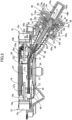
- the present invention relates to an electric parking brake device including a screw shaft that is connected to a brake cable; an actuator case that supports the screw shaft movably in an axial direction thereof; an electric motor that is supported by the actuator case rotatably forward and backward; a motion conversion mechanism that has a nut to be screwed onto the screw shaft, enables conversion from a rotational motion generated in the electric motor to a linear motion of the screw shaft, and is accommodated in the actuator case; and a rotation restricting means that restricts a rotational motion of the screw shaft, in which switching between a parking brake state reached by pulling the brake cable and a non-parking brake state reached by loosening the brake cable is performed by a change in a rotational direction of the electric motor.
- An electric parking brake device that switches between a state in which a parking brake force is obtained by pulling a brake cable and a state in which a parking brake force is released by loosening the brake cable by a change in the rotational direction of an electric motor is known in PTL 1.
- the electric parking brake device disclosed in PTL 1 has a rotation restricting means, configured by a projection portion provided in the screw shaft and a groove formed in the actuator case so as to be entered by the projection portion, for restricting the rotation of the screw shaft, since a clearance is present between the projection portion and the groove, the projection portion collides with the side surface of the groove and causes a slapping sound when the rotational direction of the screw shaft is changed to switch between the parking brake state and the parking brake release state and may cause a large operating sound.
- the projection portion is kept pressed strongly against the side surface of the groove during movement in the axial direction of the screw shaft when a rotational motion is restricted by the rotation restricting means, the sliding resistance of the projection portion becomes large, thereby increasing wear of the projection portion and the actuator case.
- the invention addresses the above situation with an object of providing an electric parking brake device that reduces an operating sound during switching between the parking brake state and the parking brake release state and reduces wear of members constituting the rotation restricting means.
- an electric parking brake device including a screw shaft that is connected to a brake cable; an actuator case that supports the screw shaft movably in an axial direction thereof; an electric motor that is supported by the actuator case rotatably forward and backward; a motion conversion mechanism that has a nut to be screwed onto the screw shaft, enables conversion from a rotational motion generated in the electric motor to a linear motion of the screw shaft, and is accommodated in the actuator case; and a rotation restricting means that restricts a rotational motion of the screw shaft, in which switching between a parking brake state reached by pulling the brake cable and a non-parking brake state reached by loosening the brake cable is performed by a change in a rotational direction of the electric motor, in which the brake cable is formed by twisting a plurality of wires so as to generate a twisting force in a fixed direction when the brake cable is pulled, and a direction in which the twisting force generated by the brake cable in a pulled
- the rotation restricting means includes a plurality of rotation restricting projection portions that are provided in an end portion of the screw shaft opposite to the brake cable and radially project from the screw shaft and a plurality of rotation restricting grooves formed in the actuator case or an insertion member accommodated and fixed in the actuator case and entered by the rotation restricting projection portions.
- the twisting force for rotationally biasing the screw shaft to the side loosening the brake cable acts on the screw shaft from the brake cable when the brake cable is pulled, it is possible to prevent components constituting the rotation restricting means from strongly colliding with each other during switching from the parking brake state to the parking brake release state, suppress the generation of a slapping sound, and reduce the operating sound.
- the screw shaft is moved in the axial direction to enter the parking brake state by pulling the brake cable, it is possible to prevent components constituting the rotation restricting means from strongly colliding with each other, reduce the driving torque of the electric motor by reducing the sliding resistance, and reduce wear of members constituting the rotation restricting means.
- the operating sound can be reduced more effectively by restricting the rotation of the screw shaft at a plurality of positions in the circumferential direction of the screw shaft.
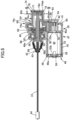
- a drum brake device 11 is provided in, for example, the left-rear wheel of a four-wheel vehicle and this drum brake device 11 includes a fixed back plate 13 having, at the center thereof, a through-hole 12 that passes through a wheel shaft 10 of the left rear wheel, first and second brake shoes 15 and 16 disposed in the back plate 13 so as to enable sliding contact with the inner periphery of a brake drum 14 that rotates together with the left rear wheel, a wheel cylinder 17 fixed to an upper portion of the back plate 13 so as to generate a force for operating the first and second brake shoes 15 and 16 in an expanded manner, a braking clearance automatic adjustment means (so-called automatic adjuster) 18 that automatically adjusts the clearance between the first and second brake shoes 15 and 16 and the brake drum 14, and a return spring 19 provided between the first and second brake shoes 15 and 16.
- a braking clearance automatic adjustment means so-called automatic adjuster
- the first and second brake shoes 15 and 16 include webs 15a and 16a formed in bows along the inner periphery of the brake drum 14, rims 15b and 16b provided in a linked manner orthogonally to the outer peripheries of the webs 15a and 16a, and linings 15c and 16c pasted to the outer peripheries of the rims 15b and 16b.
- the outer end portions of a pair of pistons 20 of the wheel cylinder 17 are disposed so as to face the webs 15a and 16a in the upper end portions of the first and second brake shoes 15 and 16.
- an anchor block 21 that functions as the fulcrum when the first and second brake shoes 15 and 16 are expanded or contracted is provided in a fixed manner in the lower portion of the back plate 13 so as to support one end portions (lower end portions in this embodiment) of the first and second brake shoes 15 and 16, and the wheel cylinder 17 is operated by the output hydraulic pressure of the master cylinder (not illustrated) operated by the brake pedal and generates a force for driving the first and second brake shoes 15 and 16 in an expanded manner using the anchor block 21 as the fulcrum.
- a coil spring 22 for biasing the lower end portions of the webs 15a and 16a of the first and second brake shoes 15 and 16 toward the anchor block 21 is provided between the lower end portions of the webs 15a and 16a and the return spring 19 for biasing the first and second brake shoes 15 and 16 in a contraction direction is provided between the upper end portions of the webs 15a and 16a of the first and second brake shoes 15 and 16.
- the braking clearance automatic adjustment means 18 includes a contraction position restricting strut 24 that is provided between the webs 15a and 16a of the first and second brake shoes 15 and 16 and stretchable by rotation of an adjustment gear 23, an adjustment lever 25 that has a feeding claw 25a to be engaged with the adjustment gear 23 and is pivotably supported by the web 16a of the second brake shoe 16, which is one of the first and second brake shoes 15 and 16, and an adjustment spring 26 that pivotally biases the adjustment lever 25 to the side rotating the adjustment gear 23 in the direction in which the contraction position restricting strut 24 is stretched.
- the contraction position restricting strut 24 restricts the contraction positions of the first and second brake shoes 15 and 16 and includes a first rod 27 that has a first engagement portion 27a to be engaged with an upper portion of the web 15a of the first brake shoe 15 of the first and second brake shoes 15 and 16, a second rod 28 that has a second engagement portion 28a to be engaged with an upper portion of the web 16a of the second brake shoe 16 and is disposed concentrically with the first rod 27, and an adjustment bolt 29 with one end portion inserted into the first rod 27 relatively movably in the axial direction and the other end portion to be screwed concentrically with the second rod 28, in which the adjustment gear 23 is disposed between the first and second rods 27 and 28 and formed in the outer periphery of the adjustment bolt 29.
- a first retaining recess 30 with which the first engagement portion 27a is engaged is provided in the upper portion of the web 15a of the first brake shoe 15 and a second retaining recess 31 with which the second engagement portion 28a is engaged is provided in the upper portion of the web 16a of the second brake shoe 16.
- the adjustment lever 25 having the feeding claw 25a to be engaged with the adjustment gear 23 is pivotably supported by the web 16a of the second brake shoe 16 via a support shaft 32 and the adjustment spring 26 is provided between the web 16a of the second brake shoe 16 and the adjustment lever 25. Furthermore, the spring force of the adjustment spring 26 is set smaller than the spring force of the return spring 19.
- the parking brake lever 34 extends upward and downward so as to partially overlap with the web 15a of the first brake shoe 15 in front view and the upper end portion of this parking brake lever 34 is connected to the upper portion of the web 15a of the first brake shoe 15 via a pin 35, and the first engagement portion 27a of the contraction position restricting strut 24 is engaged with the upper portion of this parking brake lever 34.
- the parking brake lever 34 When the parking brake of the vehicle is operated, the parking brake lever 34 is driven pivotally counterclockwise about the pin 35 as the fulcrum and this pivot of the parking brake lever 34 causes a force for pressing the lining 16c of the brake shoe 16 against the inner periphery of the brake drum 14 to act on the second brake shoe 16 via the contraction position restricting strut 24.
- the parking brake lever 34 is continuously driven pivotally counterclockwise in Fig. 1
- the parking brake lever 34 is pivoted about the engagement point with respect to the first engagement portion 27a of the contraction position restricting strut 24 as the fulcrum, the first brake shoe 15 is operated in an expanded manner via the pin 35 and the lining 15c of the first brake shoe 15 is pressed against the inner periphery of the brake drum 14. That is, the parking brake lever 34 is operated at an operation position at which the linings 15c and 16c of the first and second brake shoes 15 and 16 are pressed against the inner periphery of the brake drum 14 and the parking brake state is obtained in this
- the parking brake lever 34 When application of a rotational driving force to the parking brake lever 34 is stopped, the parking brake lever 34 is returned to a non-operation position together with the first and second brake shoes 15 and 16 operated in a direction away from the inner periphery of the brake drum 14 by the spring force of the return spring 19 and the parking brake lever 34 is biased toward the non-operation position.
- a cylindrical first bearing portion 53a that rotatably supports a motor shaft 54 is provided in a projecting manner in one end portion in the axial direction of a motor case 53 of the electric motor 40, the one end portion of the motor shaft 54 passes through the first bearing portion 53a and projects from one end portion of the motor case 53, and a bottomed-cylindrical second bearing portion 53b that rotatably supports the other end portion of the motor shaft 54 is provided in a projecting manner in the other end portion in the axial direction of the motor case 53.
- the lid portion 48a is formed in a dish shape opened toward the first accommodating cylindrical portion 45 and an annular recess 58 concentric with the first accommodating cylindrical portion 45 having a circular cross section is formed at the open end of this lid portion 48a.
- an annular fitting projection portion 59 to be fitted to the annular recess 58 is provided in a projecting manner in the opening end portion of the first accommodating cylindrical portion 45.
- the lid portion 48a and the first accommodating cylindrical portion 45 are bonded to each other in the state in which the fitting projection portion 59 is fitted to the annular recess 58.
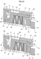
- the insertion member 74 is integrally provided with an extended cylindrical portion 74b that is continuous to the guide cylindrical portion 74a and enters the gear chamber 60, a plurality of (for example, two) mount arm portions 74c that overhang outward to the side from the end portion of the guide cylindrical portion 74a close to the gear chamber 60 along the inner surface of the cover plate portion 49a of the second cover member 49, and one support arm portion 74d that overhands outward to the side from the end portion of the guide cylindrical portion 74a close to the gear chamber 60 along the inner surface of the cover plate portion 49a.
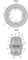
- a rotation restricting means 73 for restricting the rotation of the screw shaft 38 is provided between the guide cylindrical portion 74a of the insertion member 74 and the screw shaft 38 and this rotation restricting means 73 includes a plurality of (two in the embodiment) rotation restricting projection portions 76b that are provided in the end portion of the screw shaft 38 on the opposite side of the brake cable 37 and radially project from the screw shaft 38 and the plurality of (two in the embodiment) rotation restricting grooves 75 that are formed in the guide cylindrical portion 74a so as to be entered by the rotation restricting projection portions 76b.
- the cap 76 is fixed to the screw shaft 38 via a pin 77 that passes through the screw shaft 38 and the bottomed cylindrical portion 76a along the one diameter line.
- This provides the pair of rotation restricting projection portions 76b in the end portion of the screw shaft 38 on the opposite side of the brake cable 37, causes the rotation restricting projection portions 76b to enter the rotation restricting grooves 75 of the insertion member 74 accommodated and fixed in the actuator case 39, and makes the screw shaft 38 movable in a direction along the axial line while being prevented from rotating about the axial line.
- the movement end of the screw shaft 38 in movement in the direction loosening the brake cable 37 is restricted by causing the cap 76 to abut against a movement restricting portion 74f accommodated and fixed in the actuator case 39 and, in the embodiment, the movement restricting portion 74f is integrally provided at the front end of the extended cylindrical portion 74b of the insertion member 74. That is, the movement restricting portion 74f is integrally provided in the front end portion of the extended cylindrical portion 74b so as to overhang radially inward from the front end portion of the extended cylindrical portion 74b.
- the retainer 82 abuts against the movement restricting portion 74f of the insertion member 74 in response to the movement in the axial direction of the nut 61, the disc springs 80 are compressed between the nut 61 and the movement restricting portion 74f, thereby enabling an increase in the load on the electric motor 40.
- the actuator case 39 is mounted to the mount cylindrical portion 85 by inserting the second accommodating cylindrical portion 46 of the first cover member 48 in the actuator case 39 of the electric actuator 36 into the large-diameter cylindrical portion 85a and engaging a C-shaped locking ring 88 mounted to the outer periphery of the second accommodating cylindrical portion 46 with a locking groove 87 formed in the inner periphery of the large-diameter cylindrical portion 85a.
- the actuator case 39 When the actuator case 39 is mounted to the mount cylindrical portion 85 of the back plate 13 as described above, the actuator case 39 is mounted to the rear side in the front-rear direction of the vehicle of the back plate 13 and the connector portion 48b is oriented to the rear side in the front-rear direction of the vehicle.
- a bellows boot 89 for covering a projection portion of the screw shaft 38 from the second accommodating cylindrical portion 46 is provided between the outer periphery of the support cylindrical portion 46b of the second accommodating cylindrical portion 46 and the outer periphery of one end portion of the screw shaft 38.
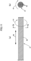
- the brake cable 37 is a bunch of a plurality of twisted wires 92 and generates a twisting force in the direction indicated by arrow 91 in Figs. 11(a) and 11(b) when pulled in the direction indicated by arrow 90 in Fig. 11(a) to obtain the parking brake state.
- a setting is made so that the direction in which the twisting force in this case acts on the screw shaft 38 is the same as the rotational direction of the nut 61 when the electric motor 40 operates in the direction loosening the brake cable 37 for switching from the parking brake state to the parking brake release state.
- the nut 61 of the motion conversion mechanism 41 capable of converting a rotational motion generated by the electric motor 40 to a linear motion of the screw shaft 38 connected to the brake cable 37 is screwed onto the screw shaft 38 movably in the axial direction within a restricted range in a direction along the axial line of the screw shaft 38, the movement restricting portion 74f that restricts the movement end in the axial direction of the screw shaft 38 in movement to the side loosening the brake cable 37 to reach the parking brake release state is provided in a fixed position in the actuator case 39, and the disc springs 80, which are resilient members, are interposed between the nut 61 and the insertion member 74 accommodated and fixed in the actuator case 39 so as to be compressed in response to movement of the nut 61 in the axial direction after the cap 76 fixed to the screw shaft 38 abuts against the movement restricting portion 74f when the screw shaft 38 moves in the axial direction to the side loosening the brake cable 37, so the load on the electric
- the electric motor 40 can be controlled appropriately and the members constituting the motion conversion mechanism 41 can be prevented from shifting to a lock state. Furthermore, since the nut 61 is relatively movable in the axial direction with respect to the screw shaft 38, generation of an operating sound in parking brake release operation can be prevented. In addition, since the disc springs 80 are provided between the insertion member 74 accommodated and fixed in the actuator case 39 and the nut 61, the strength of the actuator case 39 does not need to be increased more than necessity.
- the internal structure of the actuator case 39 can be simplified while suppressing an increase in the number of components by providing the disc springs 80 between the nut 61 and the movement restricting portion 74f provided integrally with the insertion member 74.
- the resilient members are the disc springs 80
- the space that needs to be reserved in the actuator case 39 to dispose the disc springs 80 can be reduced and the actuator case 39 can be small-sized.
- the brake cable 37 is formed by twisting the plurality of wires 92 so as to generate a twisting force when pulled and the direction in which the twisting force acts on the screw shaft 38 is the same as the rotational direction of the nut 61 when the brake cable 37 is loosened, even if the nut 61 is rotated so as to obtain the parking brake state, the screw shaft 38 is rotated and reaches a rotary position A indicated by the dotted line in Fig.
- the rotation restricting projection portions 76b are returned to the vicinity of a rotary position B indicated by the dotted line in Fig. 9 by the twisting force from the brake cable 37 when the parking brake state is maintained. Even when the rotation restricting projection portions 76b of the cap 76 reach the rotary position B by the backward rotation of the nut 61 during switching from the parking brake state to the parking brake release state and make contact with the side surface of the rotation restricting grooves 75 of the insertion member 74, it is possible to prevent the cap 76 and the insertion member 74 from strongly colliding with each other, suppress the generation of a slapping sound, and reduce the operating sound.
- the rotation restricting means 73 includes the plurality of rotation restricting projection portions 76b that are provided in the end portion of the screw shaft 38 opposite to the brake cable 37 and radially project from the screw shaft 38 and the plurality of the rotation restricting grooves 75 formed in the insertion member 74 so as to be entered by the rotation restricting projection portions 76b, the operating sound can be reduced more effectively by restricting the rotation of the screw shaft 38 at a plurality of positions in the circumferential direction of the screw shaft 38.
Landscapes
- Engineering & Computer Science (AREA)
- General Engineering & Computer Science (AREA)
- Mechanical Engineering (AREA)
- Transportation (AREA)
- Braking Arrangements (AREA)
- Braking Systems And Boosters (AREA)
- Braking Elements And Transmission Devices (AREA)
Applications Claiming Priority (3)
| Application Number | Priority Date | Filing Date | Title |
|---|---|---|---|
| JP2018068037 | 2018-03-30 | ||
| EP18912782.2A EP3779230B1 (de) | 2018-03-30 | 2018-12-06 | Elektrische feststellbremsenvorrichtung |
| PCT/JP2018/044929 WO2019187361A1 (ja) | 2018-03-30 | 2018-12-06 | 電動パーキングブレーキ装置 |
Related Parent Applications (2)
| Application Number | Title | Priority Date | Filing Date |
|---|---|---|---|
| EP18912782.2A Division EP3779230B1 (de) | 2018-03-30 | 2018-12-06 | Elektrische feststellbremsenvorrichtung |
| EP18912782.2A Division-Into EP3779230B1 (de) | 2018-03-30 | 2018-12-06 | Elektrische feststellbremsenvorrichtung |
Publications (2)
| Publication Number | Publication Date |
|---|---|
| EP4293247A2 true EP4293247A2 (de) | 2023-12-20 |
| EP4293247A3 EP4293247A3 (de) | 2024-03-13 |
Family
ID=68060559
Family Applications (2)
| Application Number | Title | Priority Date | Filing Date |
|---|---|---|---|
| EP23207058.1A Pending EP4293247A3 (de) | 2018-03-30 | 2018-12-06 | Elektrische feststellbremsvorrichtung |
| EP18912782.2A Active EP3779230B1 (de) | 2018-03-30 | 2018-12-06 | Elektrische feststellbremsenvorrichtung |
Family Applications After (1)
| Application Number | Title | Priority Date | Filing Date |
|---|---|---|---|
| EP18912782.2A Active EP3779230B1 (de) | 2018-03-30 | 2018-12-06 | Elektrische feststellbremsenvorrichtung |
Country Status (5)
| Country | Link |
|---|---|
| US (2) | US11794710B2 (de) |
| EP (2) | EP4293247A3 (de) |
| JP (2) | JP7240379B2 (de) |
| CN (1) | CN111936761B (de) |
| WO (1) | WO2019187361A1 (de) |
Families Citing this family (2)
| Publication number | Priority date | Publication date | Assignee | Title |
|---|---|---|---|---|
| EP3771844A4 (de) * | 2018-03-30 | 2021-12-22 | Nissin Kogyo Co., Ltd. | Elektrische feststellbremsenvorrichtung |
| EP4293247A3 (de) * | 2018-03-30 | 2024-03-13 | Hitachi Astemo, Ltd. | Elektrische feststellbremsvorrichtung |
Family Cites Families (21)
| Publication number | Priority date | Publication date | Assignee | Title |
|---|---|---|---|---|
| PL176894B1 (pl) * | 1995-07-28 | 1999-08-31 | Edward Sosna | Hamulec najazdowo hamowanych przyczep |
| KR100279565B1 (ko) * | 1998-12-29 | 2001-04-02 | 홍영철 | 상이한 꼬임밀도와 꼬임방향을 갖는 고무 보강용 스틸코드 및 그 제조장치 |
| JP4371286B2 (ja) * | 2000-04-12 | 2009-11-25 | 日清紡ホールディングス株式会社 | 操作ケーブルの接続装置 |
| US6533082B2 (en) * | 2000-12-01 | 2003-03-18 | Dura Global Technologies, Inc. | Electric parking brake |
| DE10361127C5 (de) * | 2003-12-22 | 2013-10-24 | Brose Fahrzeugteile GmbH & Co. Kommanditgesellschaft, Würzburg | Stelleinrichtung, insbesondere Kraftfahrzeug-Feststellbremse |
| JP4176669B2 (ja) * | 2004-03-26 | 2008-11-05 | 本田技研工業株式会社 | パーキングブレーキ装置 |
| EP1767419B1 (de) * | 2004-06-30 | 2012-10-03 | HI-LEX Corporation, Inc. | Elektrisch angetriebene kabelantriebsvorrichtung und elektrische bremsvorrichtung |
| JP4928085B2 (ja) * | 2004-06-30 | 2012-05-09 | 株式会社ハイレックスコーポレーション | 電動ブレーキ装置 |
| EP1619398B1 (de) * | 2004-07-23 | 2007-05-02 | Siemens Aktiengesellschaft | Stelleinrichtung, insbesondere Kraftfahrzeugfeststellbremse |
| WO2007087914A1 (de) * | 2006-01-16 | 2007-08-09 | Continental Automotive Gmbh | Stelleinrichtung, insbesondere für eine kraftfahrzeug-feststellbremse |
| DE102006018625A1 (de) * | 2006-04-21 | 2007-10-25 | Siemens Ag | Stelleinrichtung, insbesondere Kraftfahrzeug-Feststellbremse |
| JP2008075799A (ja) * | 2006-09-22 | 2008-04-03 | Aisin Seiki Co Ltd | 直動アクチュエータ |
| JP2012159164A (ja) * | 2011-02-02 | 2012-08-23 | Advics Co Ltd | 電動駐車ブレーキ装置 |
| JP2015110967A (ja) * | 2013-12-06 | 2015-06-18 | 曙ブレーキ工業株式会社 | ドラム式電動駐車ブレーキ装置用アクチュエータユニット |
| US10138966B2 (en) | 2014-03-11 | 2018-11-27 | Nissin Kogyo Co., Ltd. | Vehicle brake apparatus |
| KR102297129B1 (ko) * | 2014-11-04 | 2021-09-02 | 현대모비스 주식회사 | 전자식 주차 브레이크 장치 |
| JP6596294B2 (ja) * | 2015-10-13 | 2019-10-23 | 日信工業株式会社 | 車両用ブレーキ装置 |
| JP6361715B2 (ja) | 2015-10-23 | 2018-07-25 | 株式会社アドヴィックス | 車両用ブレーキ |
| JP2017082834A (ja) | 2015-10-23 | 2017-05-18 | 株式会社アドヴィックス | 車両用ブレーキ |
| EP4293247A3 (de) * | 2018-03-30 | 2024-03-13 | Hitachi Astemo, Ltd. | Elektrische feststellbremsvorrichtung |
| EP3771844A4 (de) * | 2018-03-30 | 2021-12-22 | Nissin Kogyo Co., Ltd. | Elektrische feststellbremsenvorrichtung |
-
2018
- 2018-12-06 EP EP23207058.1A patent/EP4293247A3/de active Pending
- 2018-12-06 WO PCT/JP2018/044929 patent/WO2019187361A1/ja active Application Filing
- 2018-12-06 US US17/043,296 patent/US11794710B2/en active Active
- 2018-12-06 EP EP18912782.2A patent/EP3779230B1/de active Active
- 2018-12-06 CN CN201880092036.3A patent/CN111936761B/zh active Active
- 2018-12-06 JP JP2020509628A patent/JP7240379B2/ja active Active
-
2023
- 2023-03-02 JP JP2023032078A patent/JP7529831B2/ja active Active
- 2023-09-20 US US18/370,576 patent/US20240010177A1/en active Pending
Also Published As
| Publication number | Publication date |
|---|---|
| US11794710B2 (en) | 2023-10-24 |
| JP7529831B2 (ja) | 2024-08-06 |
| US20240010177A1 (en) | 2024-01-11 |
| CN111936761A (zh) | 2020-11-13 |
| JP7240379B2 (ja) | 2023-03-15 |
| EP4293247A3 (de) | 2024-03-13 |
| EP3779230A1 (de) | 2021-02-17 |
| EP3779230A4 (de) | 2021-12-22 |
| US20210016762A1 (en) | 2021-01-21 |
| CN111936761B (zh) | 2022-04-19 |
| EP3779230B1 (de) | 2023-12-06 |
| JPWO2019187361A1 (ja) | 2021-03-25 |
| WO2019187361A1 (ja) | 2019-10-03 |
| JP2023067950A (ja) | 2023-05-16 |
Similar Documents
| Publication | Publication Date | Title |
|---|---|---|
| US20240010177A1 (en) | Electric parking brake device | |
| CN109114132B (zh) | 电动致动器及电动驻车制动装置 | |
| US20210394734A1 (en) | Electronic parking brake system | |
| EP3418142B1 (de) | Trommelbremssystem | |
| JP2018502004A (ja) | ドラムブレーキの内部にある駐車ブレーキレバーの電動アクチュエータ | |
| CN109649365B (zh) | 电动驻车制动装置 | |
| EP3771844A1 (de) | Elektrische feststellbremsenvorrichtung | |
| KR20230133246A (ko) | 전동식 주차 브레이크 및 이를 포함하는 차량 | |
| CN111226055B (zh) | 电动驻车制动装置 | |
| CN216589680U (zh) | 制动器的电子驻车执行器以及车辆 | |
| JP2019007536A (ja) | 車両用ドラムブレーキ装置 | |
| KR20220082450A (ko) | 전자제어식 브레이크 장치 | |
| CN118224207A (zh) | 鼓式制动器、车辆及车辆的控制方法 | |
| JP2008169952A (ja) | ブレーキ装置 | |
| JP2014005845A (ja) | ブレーキ装置 |
Legal Events
| Date | Code | Title | Description |
|---|---|---|---|
| PUAI | Public reference made under article 153(3) epc to a published international application that has entered the european phase |
Free format text: ORIGINAL CODE: 0009012 |
|
| STAA | Information on the status of an ep patent application or granted ep patent |
Free format text: STATUS: THE APPLICATION HAS BEEN PUBLISHED |
|
| AC | Divisional application: reference to earlier application |
Ref document number: 3779230 Country of ref document: EP Kind code of ref document: P |
|
| AK | Designated contracting states |
Kind code of ref document: A2 Designated state(s): AL AT BE BG CH CY CZ DE DK EE ES FI FR GB GR HR HU IE IS IT LI LT LU LV MC MK MT NL NO PL PT RO RS SE SI SK SM TR |
|
| REG | Reference to a national code |
Ref country code: DE Ref legal event code: R079 Free format text: PREVIOUS MAIN CLASS: F16D0125480000 Ipc: F16D0065220000 |
|
| PUAL | Search report despatched |
Free format text: ORIGINAL CODE: 0009013 |
|
| AK | Designated contracting states |
Kind code of ref document: A3 Designated state(s): AL AT BE BG CH CY CZ DE DK EE ES FI FR GB GR HR HU IE IS IT LI LT LU LV MC MK MT NL NO PL PT RO RS SE SI SK SM TR |
|
| RIC1 | Information provided on ipc code assigned before grant |
Ipc: F16D 125/48 20120101ALI20240206BHEP Ipc: F16D 51/22 20060101ALI20240206BHEP Ipc: F16D 125/60 20120101ALI20240206BHEP Ipc: F16D 125/40 20120101ALI20240206BHEP Ipc: F16D 121/24 20120101ALI20240206BHEP Ipc: B60T 13/74 20060101ALI20240206BHEP Ipc: F16D 65/22 20060101AFI20240206BHEP |